

Page 1

User Manual
020-102264-03
Boxer 2K
Boxer 2K20 (Bc.3), Boxer 2K25
(Bc.4), Boxer 2K30 (Bc.5)
Page 2

NOTICES
COPYRIGHT AND TRADEMARKS
yright © 2016 Christie Digital Systems USA Inc. All rights reserved.
Cop
All brand names and product names are trademarks, registered trademarks or trade names of their respective holders.
GENERAL
Every effort has been made to ensure accuracy, however in some cases changes in the products or availability could occur which may not be reflected in this
document. Christie reserves the right to make changes to specifications at any time without notice. Performance specifications are typical, but may vary
depending on conditions beyond Christie's control such as maintenance of the product in proper working conditions. Performance specifications are based on
information available at the time of printing. Christie makes no warranty of any kind with regard to this material, including, but not limited to, implied
warranties of fitness for a particular purpose. Christie will not be liable for errors contained herein or for incidental or consequential damages in connection
with the performance or use of this material. Canadian manufacturing facility is ISO 9001 and 14001 certified.
WARRANTY
Products are warranted under Christie’s standard limited warranty, the complete details of which are available by contacting your Christie dealer or Christie. In
addition to the other limitations that may be specified in Christie’s standard limited warranty and, to the extent relevant or applicable to your product, the
warranty does not cover:
Problems or damage occurring during shipment, in either direction.
a.
Projector lamps (See Christie’s separate lamp program policy).
b.
Problems or damage caused by use of a projector lamp beyond the recommended lamp life, or use of a lamp other than a Christie lamp supplied by
c.
Christie or an authorized distributor of Christie lamps.
Problems or damage caused by combination of a product with non-Christie equipment, such as distribution systems, cameras, DVD players, etc., or use
d.
of a product with any non-Christie interface device.
Problems or damage caused by the use of any lamp, replacement part or component purchased or obtained from an unauthorized distributor of Christie
e.
lamps, replacement parts or components including, without limitation, any distributor offering Christie lamps, replacement parts or components through
the internet (confirmation of authorized distributors may be obtained from Christie).
Problems or damage caused by misuse, improper power source, accident, fire, flood, lightening, earthquake or other natural disaster.
f.
Problems or damage caused by improper installation/alignment, or by equipment modification, if by other than Christie service personnel or a Christie
g.
authorized repair service provider.
Problems or damage caused by use of a product on a motion platform or other movable device where such product has not been designed, modified or
h.
approved by Christie for such use.
Problems or damage caused by use of a projector in the presence of an oil-based fog machine or laser-based lighting that is unrelated to the projector.
i.
For LCD projectors, the warranty period specified in the warranty applies only where the LCD projector is in “normal use” which means the LCD projector
j.
is not used more than 8 hours a day, 5 days a week.
Except where the product is designed for outdoor use, problems or damage caused by use of the product outdoors unless such product is protected from
k.
precipitation or other adverse weather or environmental conditions and the ambient temperature is within the recommended ambient temperature set
forth in the specifications for such product.
Defects caused by normal wear and tear or otherwise due to normal aging of a product.
l.
The warranty does not apply to any product where the serial number has been removed or obliterated. The warranty also does not apply to any product sold
by a reseller to an end user outside of the country where the reseller is located unless (i) Christie has an office in the country where the end user is located or
(ii) the required international warranty fee has been paid.
The warranty does not obligate Christie to provide any on site warranty service at the product site location.
PREVENTATIVE MAINTENANCE
Preventative maintenance is an important part of the continued and proper operation of your product. Please see the Maintenance section for specific
maintenance items as they relate to your product. Failure to perform maintenance as required, and in accordance with the maintenance schedule specified by
Christie, will void the warranty.
REGULATORY
The product has been tested and found to comply with the limits for a Class A digital device, pursuant to Part 15 of the FCC Rules. These limits are designed
to provide reasonable protection against harmful interference when the product is operated in a commercial environment. The product generates, uses, and
can radiate radio frequency energy and, if not installed and used in accordance with the instruction manual, may cause harmful interference to radio
communications. Operation of the product in a residential area is likely to cause harmful interference in which case the user will be required to correct the
interference at the user’s own expense.
CAN ICES-3 (A) / NMB-3 (A)
이 기기는 업무용(A급)으로 전자파적합등록을 한 기기이오니 판매자 또는 사용자는 이점을 주의하시기 바라며, 가정 외의 지역에서 사용하는 것을 목적으로 합니다.
ENVIRONMENTAL
The product is designed and manufactured with high-quality materials and components that can be recycled and reused. This symbol
and electronic equipment, at their end-of
to local regulations. In the European Union, there are separate collection systems for used electrical and electronic products. Please help us to conserve the
environment we live in!
-life, should be disposed of separately from regular waste. Please dispose of the product appropriately and according
means that electrical
Page 3

Content
Introduction...................................................... 7
Safet
y and warning guidelines........................................... 7
Light intensity hazard...............................................8
Product labels................................................... 8
Projector overview..................................................10
Contact your dealer.................................................10
Key features......................................................10
How the projector works..............................................11
List of components..................................................11
Site requirements.................................................. 11
Physical operating environment........................................11
Power connection................................................ 11
Projector components................................................12
IR remote keypad..................................................13
Display panel components.............................................16
Turning the projector on..............................................17
Projector LED status indicators........................................17
Projector LED shutter indicators....................................... 18
Turning the projector off..............................................18
Adjusting the image............................................... 19
Selecting screen image orientation........................................19
Setting the image resize preset..........................................19
Adjusting lens settings...............................................20
Adjusting offset..................................................20
Resetting the lens to home position.....................................20
Aligning the image with lens zoom and focus............................... 20
Locking the lens motor.............................................21
Determining what lens warnings are displayed.............................. 21
Adjusting primary colors..............................................21
DMD color correction................................................ 22
Adjusting color by precise chromaticity values...............................22
Adjusting color by saturation......................................... 22
Signal color correction............................................... 22
Boxer 2K Boxer 2K20 (Bc.3), Boxer 2K25 (Bc.4), Boxer 2K30 (Bc.5) User Manual 3
020-102264-03 R
Copyright © 2016 Christie Digital Systems USA Inc. All rights reserved.
ev. 1 (10-2016)
Page 4

Content
Adjusting color by temperature........................................22
Adjusting color v
alues based on gamma function.............................23
Selecting the color correction mode.....................................23
Correcting for ambient light..........................................23
Setting the frame delay...............................................23
Enabling film mode detect.............................................24
Adjusting the image sharpness..........................................24
Enabling edge blending...............................................24
Blending black levels for multiple projectors..................................25
Enabling black level blending......................................... 25
Adjusting the black level blends........................................25
Resetting black level blending.........................................26
Geometry correction.................................................26
Enabling warping.................................................26
Correcting the shape of a keystoned image................................ 26
Configuring system settings.........................................29
Setting the date on the projector.........................................29
Setting the time on the projector.........................................29
Synchronizing the date and time.........................................29
Changing the splash screen............................................30
Determining the on-screen display position.................................. 30
Changing the language...............................................30
Resuming projector operation after an AC power interruption.......................30
Enabling direct pass-through of HDMI, 3G, and DisplayPort input signals................31
Adjusting lamp power................................................31
BrightSelect™.....................................................31
Selecting lamps using BrightSelect™.....................................31
Configuring communications........................................32
Enabling projector communication........................................32
Setting the remote access level..........................................32
Communicating with Boxer 2K through Art-Net................................33
Art-Net channel listing............................................. 34
Index list for the input channel........................................35
Working with macros................................................37
Adding a macro..................................................37
Copying a macro.................................................38
Editing a macro..................................................38
Boxer 2K Boxer 2K20 (Bc.3), Boxer 2K25 (Bc.4), Boxer 2K30 (Bc.5) User Manual 4
020-102264-03 R
Copyright © 2016 Christie Digital Systems USA Inc. All rights reserved.
ev. 1 (10-2016)
Page 5

Content
Deleting a macro.................................................38
Configuring the GPIO................................................39
GPIO connector..................................................39
Setting up projector profiles.........................................41
Creating a new projector profile......................................... 41
Importing a projector profile............................................41
R
estoring settings from a profile.........................................41
Renaming a projector profile............................................42
Exporting a projector profile to an external device..............................42
Deleting a projector profile.............................................42
Backup, restore, and upgrade projector files............................43
Upgrading the Boxer 2K software.........................................43
Exporting backup settings to an external device............................... 43
Importing a file from an external device to restore settings........................ 44
Restoring projector default settings.......................................44
Diagnostic tools ..................................................45
Viewing projector information...........................................45
Viewing lamp information............................................. 45
Adding lamp end-of-life indicator.........................................45
Freezing an image..................................................45
Test patterns..................................................... 46
Selecting a test pattern.............................................46
Modifying grey level test pattern characteristics..............................46
Modifying ramp test pattern characteristics................................ 46
Modifying grid test pattern characteristics................................. 47
Enabling a specific test pattern color.....................................47
Viewing Boxer 2K status..............................................47
Monitoring projector and lamps with Christie TAP...............................47
Running the Boxer 2K interrogator........................................48
Monitoring Boxer 2K with SNMP..........................................48
Setting the SNMP read community string..................................48
Configuring traps.................................................48
Defining a trap IP address...........................................49
Restoring factory default settings.........................................49
Specifications....................................................50
Boxer 2K Boxer 2K20 (Bc.3), Boxer 2K25 (Bc.4), Boxer 2K30 (Bc.5) User Manual 5
020-102264-03 R
Copyright © 2016 Christie Digital Systems USA Inc. All rights reserved.
ev. 1 (10-2016)
Page 6

Content
Display.........................................................50
Control signal compatibilit
y............................................ 50
Optional input cards.................................................51
Temperature sensor thresholds..........................................51
Warning thresholds for fans............................................52
Warning threshold for liquid cooling module..................................53
Power requirements.................................................53
Physical specifications................................................54
Accessories...................................................... 54
Regulatory.......................................................55
Safety....................................................... 55
Approvals..................................................... 55
Electro-magnetic compatibility........................................ 56
Environment..................................................... 56
Boxer 2K Boxer 2K20 (Bc.3), Boxer 2K25 (Bc.4), Boxer 2K30 (Bc.5) User Manual 6
020-102264-03 R
Copyright © 2016 Christie Digital Systems USA Inc. All rights reserved.
ev. 1 (10-2016)
Page 7

Introduction
This manual is intended for
projection systems.
For complete Boxer 2K product documentation and technical support, go to www.christiedigital.com.
Christie qualified installers and trained operators of Christie Boxer 2K
Safety and warning guidelines
Warning! F
• Do not look directly into the lens or at the lamp. The extremely high brightness can cause
permanent ey
• EXTREME BRIGHTNESS! When accessing a restricted access location for product service or
maintenance, avoid exposure to the product beam path by turning the product power off and
disconnecting the product from AC power, or by shuttering the lamp to avoid emissions from
the front aperture.
• FIRE HAZARD! Keep hands, clothes, and all combustible material away from the concentrated
light beam of the lamps.
• SHOCK HAZARD! Power supply uses double pole/neutral fusing. Disconnect all power sources
before opening the product.
• FIRE HAZARD! Do not exceed 30 A for the breaker to power Input 1 on the projector.
• Install the product near an easily accessible AC receptacle.
• FIRE AND SHOCK HAZARD! Use only the attachments, accessories, tools, and replacement
parts specified by Christie.
ailure to comply with the following could result in death or serious injury.
e damage.
Caution! F
• This product must be operated in an environment that meets the operating range as specified
in this manual.
•
TRIP OR FIRE HAZARD! Position all cables where they cannot contact hot surfaces, be pulled,
be tripped over, or damaged by persons walking on or objects rolling over the cables.
• The American Conference of Governmental Industrial Hygienists (ACGIH) recommends
occupational UV exposure for an 8-hour day to be less than 0.1 microwatts per square
centimeters of effective UV radiation. A workplace evaluation is advised to assure employees
are not exposed to cumulative radiation levels exceeding the government guidelines for your
area. Be aware that some medications are known to increase sensitivity to UV radiation.
Boxer 2K Boxer 2K20 (Bc.3), Boxer 2K25 (Bc.4), Boxer 2K30 (Bc.5) User Manual 7
020-102264-03 R
Copyright © 2016 Christie Digital Systems USA Inc. All rights reserved.
ev. 1 (10-2016)
ailure to comply with the following could result in minor or moderate injury.
Page 8

Light intensity hazard
Introduction
This projector has been classified as Risk Group 3 as per the
IEC62471 standard due to possible
hazardous optical and thermal radiation being emitted.
Warning! F
ailure to comply with the following could result in serious injury.
• PERMANENT/TEMPORARY BLINDNESS HAZARD! No direct exposure to the beam must be
permitted.
•
PERMANENT/TEMPORARY BLINDNESS HAZARD! Operators must control access to the beam
within the hazard distance or install the product at the height (greater than or equal to 3.0 m
from the floor to the beam) that prevents exposure of spectators' eyes within the hazard
distance.
• EXTREME BRIGHTNESS! Do not place reflective objects in the product light path.
Product labels
Learn about the labels that may be used on the product. Labels on your product may be yellow or
black and white.
General hazards
General hazard.
Electric shock hazard. To avoid personal injury, disconnect all power sources before
performing maintenance or service.
Electrocution hazard. To avoid personal injury, always disconnect all power sources before
performing maintenance or service procedures.
Fire hazard. To avoid personal injury and property damage, follow the instructions provided in
this document.
Hot surface hazard. To avoid personal injury, allow the product to cool for the recommended
cool down time before performing maintenance or service.
Burn hazard. To avoid personal injury, allow the product to cool for the recommended cool
down time before performing maintenance or service.
Explosive material hazard. To avoid personal injury, disconnect all power sources before
performing maintenance or service, and wear
Christie-approved protective clothing.
Boxer 2K Boxer 2K20 (Bc.3), Boxer 2K25 (Bc.4), Boxer 2K30 (Bc.5) User Manual 8
020-102264-03 R
Copyright © 2016 Christie Digital Systems USA Inc. All rights reserved.
ev. 1 (10-2016)
Page 9
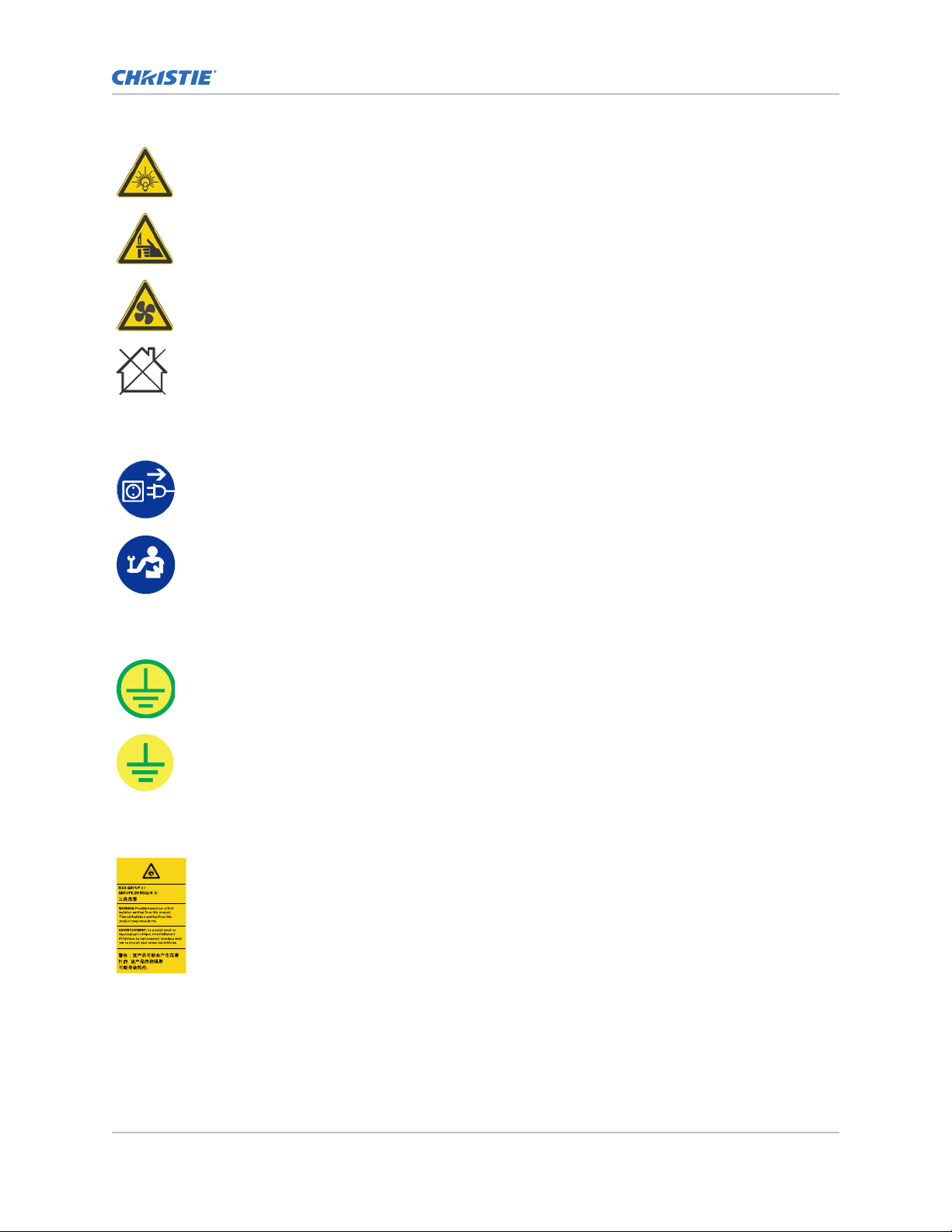
Bright light hazard. To avoid personal injury, never look directly at the light source.
Pinch hazard. To avoid personal injury, keep hands clear and loose clothing tied back.
Fan hazard. To avoid personal injury, keep hands clear and loose clothing tied back. Always
disconnect all power sources before performing maintenance or service procedures.
Not for household use.
Mandatory action
Disconnect all power sources before performing maintenance or service procedures.
Introduction
Consult the service manual.
Electrical labels
Indicates the presence of a protective earth ground.
Indicates the presence of an earth ground.
Additional hazard labels
Risk Group 3 warning: Indicates a potential optical radiation hazard emitted from
this product. Thermal r
adiation emitted from this product may cause burns.
Boxer 2K Boxer 2K20 (Bc.3), Boxer 2K25 (Bc.4), Boxer 2K30 (Bc.5) User Manual 9
020-102264-03 R
Copyright © 2016 Christie Digital Systems USA Inc. All rights reserved.
ev. 1 (10-2016)
Page 10

Projector overview
Introduction
Learn about the
The Boxer 2K is a professional quality, easy-to-use projector using Digital Light Processing (DLPTM)
technology from Texas Instruments. Integrating smoothly into traditional projection environments, the
Boxer 2K interfaces with local networks throughout the world, for multimedia presentations from a
variety of formats, to offer stunning wide screen images.
Boxer 2K projector.
Contact your dealer
Record the information about your projector and keep this information with your records to assist with
the servicing of your projector. If you encounter a problem with your Christie projector, contact your
dealer.
Purchase record
Dealer:
Dealer or Christie Sales/Service contact phone number:
Projector serial number:
The serial number can be found on the license label located on the displa
Purchase date:
Installation date:
Ethernet settings
y panel
Default gateway
Projector IP address
Subnet mask
Key features
Understand the important features of the projector
• Built in warp and blend of projected images
• Near field communication
• Multi-lamp module with no lamp alignment required
• Improved lens mount with bayonet style insertion
• Single phase 200-240 V
• Side access to optical adjustments
• Omnidirectional operation
• TruLife electronics
• New LCD display to provide information at-a-glance
.
Boxer 2K Boxer 2K20 (Bc.3), Boxer 2K25 (Bc.4), Boxer 2K30 (Bc.5) User Manual 10
020-102264-03 R
Copyright © 2016 Christie Digital Systems USA Inc. All rights reserved.
ev. 1 (10-2016)
Page 11

Introduction
How the projector works
Boxer 2K accepts a variety of input signals for projection on front or rear projection screens,
The
typical in commercial or other large screen applications.
High-brightness light is generated by mercury vapor lamps, then modulated by three Digital
Micromirror Device (DMD) panels responding to incoming data streams of digitized red, green and blue
color information. As these digital streams flow from the source, light from the responding “on” pixels
of each panel is reflected, converged and then projected to the screen through one or more projection
lenses, where all pixel reflections are superimposed in sharp full-color images.
List of components
Verify all components were received with the projector.
• Power cord for full brightness, multi-lamp operation
• Power cord for limited power, single lamp operation
• IR remote keypad
Site requirements
To safely install and operate the projector, the installation location must have restricted access for
authorized personnel only and meet these minimum requirements.
Physical operating environment
Provides specifications for the operating environment.
• Ambient temperature (operating) 5 to 40°C (41 to 104°F) up to 1500 ft
• Humidity (non-condensing) 10 to 80%
• Operating altitude: 10,000 ft maximum at 5 to 25 degrees Celsius ambient
Power connection
The projector uses an innovative dual AC inlet power system that offers two power modes.
To operate at full brightness (six lamps), power the projector using AC Input 1 if the appropriate high
power source is available. To operate in limited power mode (single lamp), power the projector using
standard lower power sources using AC Input 2. A different power cord is provided for each power
source. A 30A rated wall breaker is required at the installation when using Input 1. A 15A rated wall
breaker is required at the installation when using Input 2.
Boxer 2K Boxer 2K20 (Bc.3), Boxer 2K25 (Bc.4), Boxer 2K30 (Bc.5) User Manual 11
020-102264-03 R
Copyright © 2016 Christie Digital Systems USA Inc. All rights reserved.
ev. 1 (10-2016)
Page 12
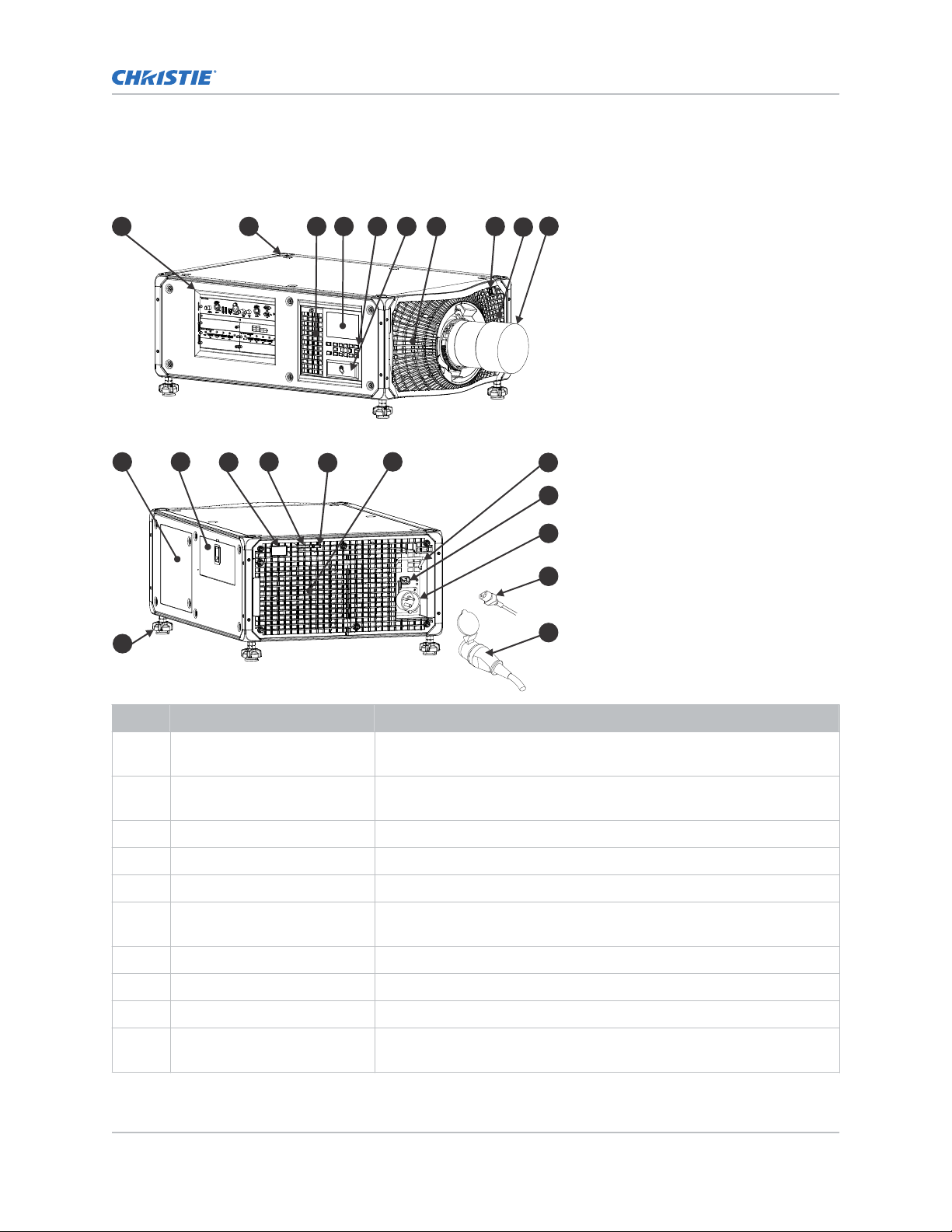
Projector components
A B C D E F
R
S
T
V
G
U
Q
H
I
J
K
L
M
N
O
P
y the main components of the projector.
Identif
Introduction
ID Component Description
A Communication and input
panel
ev. 1 (10-2016)
B Mounting and rigging holes M12 x 1.75 holes for projector feet installation and offer mounting and
C User interface air filter door Provides to the user interface air filter.
D Display panel Displays the projector menus and status.
E Keypad interface Controls the projector.
F Christie TAP Enables Android devices to communicate with the projector using near field
G Electronics-side filter door Provides access to the electronics-side air filter.
H Front IR Receives transmissions from the IR remote.
I Lamp-side filter door Provides access to the lamp-side air filter.
J Projection lens A variety of lenses can be used with the projector. Available lenses are
Boxer 2K Boxer 2K20 (Bc.3), Boxer 2K25 (Bc.4), Boxer 2K30 (Bc.5) User Manual 12
020-102264-03 R
Copyright © 2016 Christie Digital Systems USA Inc. All rights reserved.
Connects media sources to either the ports on the option cards or the
IMXB
.
rigging points.
communication.
listed in accessories.
Page 13

Introduction
ID Component Description
K Adjustable feet Raise or lower these feet when positioning the projector to make sure it
is lev
el on all sides so the displayed image appears rectangular without
any keystone.
L Service compartment Access to fold mirror, optical zoom/focus, and DMD convergence
adjustments.
M Tool box Provides tools for Christie qualified technicians.
N Rear IR Receives transmissions from the IR remote.
O LED status indicator Indicates lamp and power status.
P Shutter LED status indicator Indicates shutter status.
Q Lamp door Access to lamp compartment.
R AC lock Locks Input 1 power cord.
S AC Input 2: limited power Use this IEC 320-C14 inlet to connect to an appropriately rated power
cord (component R) provided for your region. For use in limited power
mode.
T AC Input 1: full power Use this IEC 309 inlet to connect to an appropriately rated power cord
(component S) provided for your region. For use in full power mode.
U Power cord: limited power Connects the provided power cord appropriately rated for your region to
AC Input 2 for limited power mode.
V Power cord: full power Connects the provided power cord appropriately rated for your region to
AC Input 1 for full power mode.
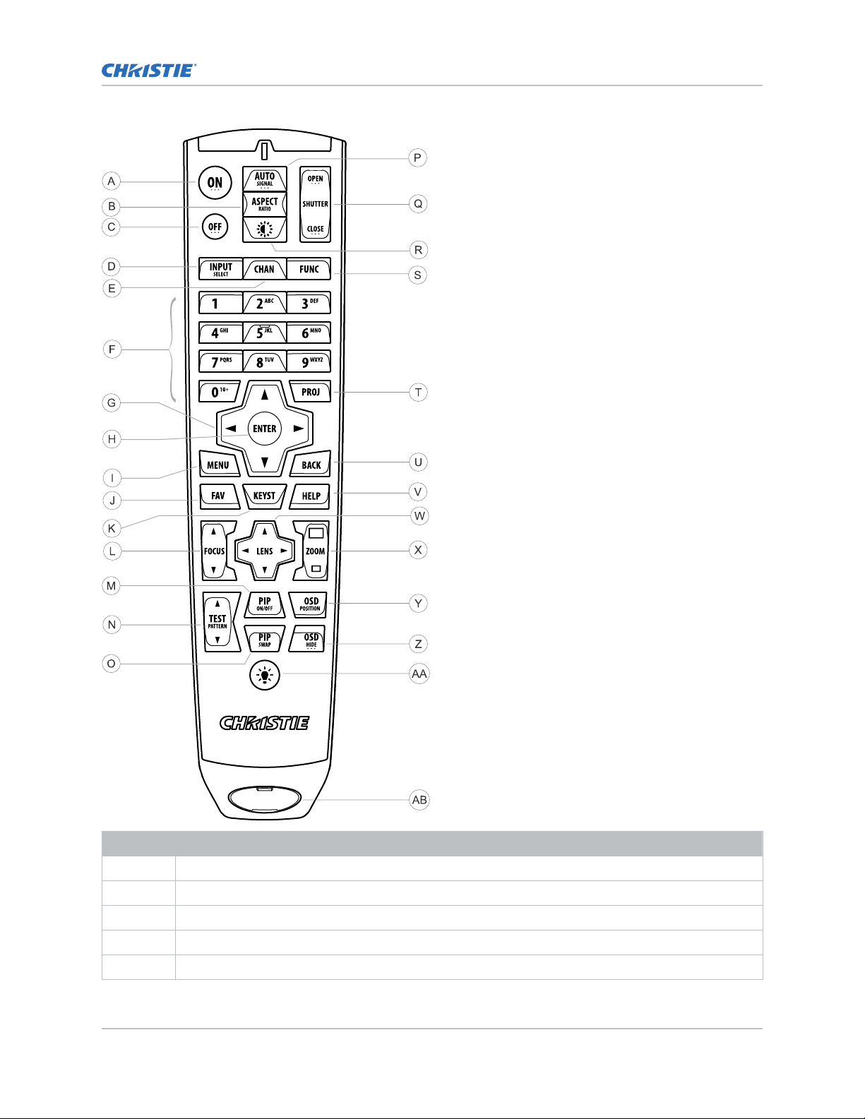
IR remote keypad
The IR remote k
powered infrared (IR) transmitter.
To use the IR remote, direct the keypad toward the projector’s front or rear IR sensor and press a
function key. One of the two IR sensors on the projector will detect the signal and relay the commands
for internal processing. The remote also offers a connector for wired connections to the projector.
eypad controls the projector by way of wireless communications from a battery-
Boxer 2K Boxer 2K20 (Bc.3), Boxer 2K25 (Bc.4), Boxer 2K30 (Bc.5) User Manual 13
020-102264-03 R
Copyright © 2016 Christie Digital Systems USA Inc. All rights reserved.
ev. 1 (10-2016)
Page 14
Introduction
Button Description
A Powers the projector lamps on.
B Opens the aspect ratio dialog.
C Turns the lamps off and puts the projector in standby.
D Selects an active or inactive input on any slot.
E Not supported.
Boxer 2K Boxer 2K20 (Bc.3), Boxer 2K25 (Bc.4), Boxer 2K30 (Bc.5) User Manual 14
020-102264-03 R
Copyright © 2016 Christie Digital Systems USA Inc. All rights reserved.
ev. 1 (10-2016)
Page 15

Button Description
F Enter a number, such as menu, item index or value.
G Use the arrows to navigate within a menu or to adjust settings.
H Selects a highlighted menu item and changes or accepts a value.
I Toggles the menus on/off.
J Not supported.
K Opens the keystone dialog.
L Adjusts the lens focus.
M Not supported.
N Displays a test pattern.
O Not supported.
P Optimizes the image automatically.
Q Opens or closes the shutter.
R Not supported.
S Initiates a custom action when a number is selected.
Introduction
T Selects a projector in multi-projector installations.
U Returns to the previous menu level or exits menus if at the top level.
V Displays context-sensitive help.
W Arrows adjust the lens offset.
X Adjust the lens zoom.
Y Opens the OSD position menu.
Z Shows or hides the OSD menus.
AA Turns the remote backlight on.
AB Male XLR connector for wired option.
Boxer 2K Boxer 2K20 (Bc.3), Boxer 2K25 (Bc.4), Boxer 2K30 (Bc.5) User Manual 15
020-102264-03 R
Copyright © 2016 Christie Digital Systems USA Inc. All rights reserved.
ev. 1 (10-2016)
Page 16
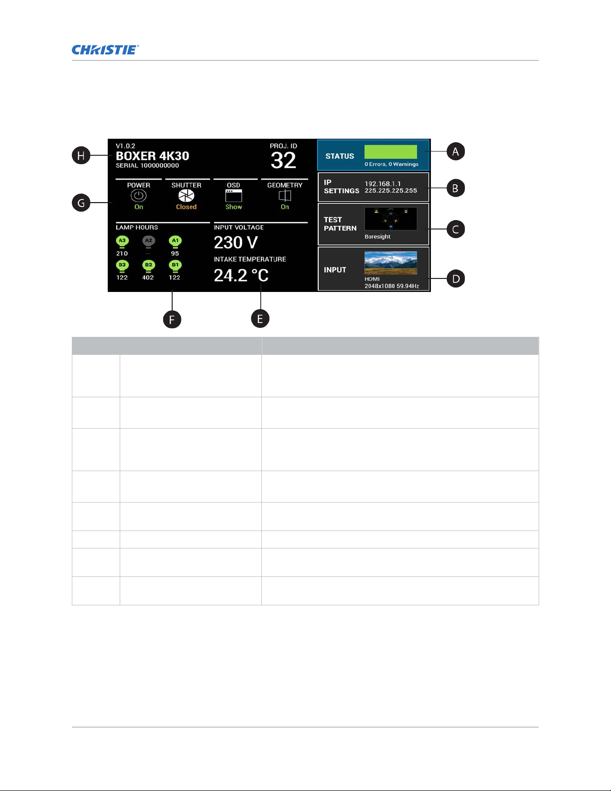
Display panel components
y the main components of the display panel (also known as the home page).
Identif
Introduction
ID Component Description
A Status Contains information about the health of the projector including
the number of w
Provides access to the status system.
B IP Settings Displays the IP address and subnet values.
Provides access to changing the IP settings.
C Test Pattern Displays the currently selected test pattern. If no test pattern is
selected, Off is displayed.
Provides access to the list of test patterns.
D Input Displays the signal for the currently selected input.
Provides access to the list of input signals.
E Power and Temperature Indicates the incoming voltage, measured in Volts, and intake
temperature, measured in Celsius.
F Lamp Hours Displays the state of the lamps and the number of hours used.
G Projector and Component
Controls
H Projector Information Provides information about the projector such as the projector
Indicates the states of the projector and its components.
name, serial number, software version, and projector ID.
arnings and errors.
Boxer 2K Boxer 2K20 (Bc.3), Boxer 2K25 (Bc.4), Boxer 2K30 (Bc.5) User Manual 16
020-102264-03 R
Copyright © 2016 Christie Digital Systems USA Inc. All rights reserved.
ev. 1 (10-2016)
Page 17

Turning the projector on
When the projector AC power supply is plugged in, the power is on.
Introduction
Warning! F
• SHOCK HAZARD! Do not attempt operation if the AC supply is not within the specified voltage
ailure to comply with the following could result in death or serious injury.
and power range, as specified on the license label.
1. Plug the projector in to AC power.
The projector automatically powers on when plugged in. The displa
y panel functionality
becomes available.
2. To turn the lamps on, press and hold the Power button until you hear a beep.
Projector LED status indicators
Identify the LED state colors and meaning.
LED State Description
Blue Solid Standby Lamps are off. Video electronics are off. Projector
status is OK.
Flashing Cool down Projector is moving to one of the two standby
states:
•
Lamps are off and video electronics are
booting up.
• Lamps are off. Video electronics and lamps are
cooling down.
Green Solid Lamps on Lamps are on. Projector status is OK.
Flashing Startup Projector is moving to lamp on state. Lamps are
striking and warming up. Video electronics are
initializing.
Yellow Solid Warning in
standby
Flashing yellow/green Warning during
startup
Flashing Warning with
lamps on
Flashing yellow/blue Warning during
cool down
Red Solid Error in
standby
Boxer 2K Boxer 2K20 (Bc.3), Boxer 2K25 (Bc.4), Boxer 2K30 (Bc.5) User Manual 17
020-102264-03 R
Copyright © 2016 Christie Digital Systems USA Inc. All rights reserved.
ev. 1 (10-2016)
Projector is in standby state. A problem exists with
the projector that does not prevent it from
operating.
Projector is in a startup state. A problem exists
with the projector that does not prevent it from
operating.
Lamps are on. A problem exists with the projector
that will not cause it to shut down.
Projector is in a cool down state. Lamps are off.
Video electronics and lamps are cooling down. A
problem exists with the projector that does not
prevent it from operating.
Projector is in standby. An error exists that
prevents the projector from starting up.
Page 18

LED State Description
Flashing Error An error with the projector exists during startup,
cool down, or when the lamps are off
proceed to shut down.
Off AC off The AC power is off.
Projector LED shutter indicators
Identif
y the shutter LED state colors and meaning.
LED State Description
Solid magenta Shutter closed The shutter is closed.
In standb
the magenta light is muted.
Off Shutter open The shutter is open.
y, the shutter is always automatically closed and
Turning the projector off
Introduction
. Projector will
When powering off in prepar
ation for inspection or maintenance, always disconnect from AC.
1. To turn the lamps off, press and hold the Power button until you hear a beep.
When powering off the projector, allow the projector to complete its cool down cycle. Do not
immediately unplug the projector if this can be avoided.
2. To turn off power to the projector, disconnect from AC power.
Boxer 2K Boxer 2K20 (Bc.3), Boxer 2K25 (Bc.4), Boxer 2K30 (Bc.5) User Manual 18
020-102264-03 R
Copyright © 2016 Christie Digital Systems USA Inc. All rights reserved.
ev. 1 (10-2016)
Page 19

Adjusting the image
Adjust the projector image.
procedures as focus may change as the lens warms.
Christie recommends warming the lens before completing these
Selecting screen image orientation
Specify the orientation to use for the image. The projector supports front projection, rear projection,
front projection inverted, or rear projection inverted.
1. Select MENU > Image Settings > Image Orientation.
2. Select the required orientation from the list.
3. To confirm your selection, press Enter.
Setting the image resize preset
Set the image resize preset to determine if an image will display in its native resolution or will resize
by maximizing the height, width, both height and width, or to the maximum size while keeping the
original aspect ratio.
1. Select MENU > Image Settings > Size & Position > Resize Presets.
2. Select the appropriate resize preset:
• Auto—Maximize for current source.
• No Resizing—Display in native resolution.
• Full Size—Fill the screen, regardless of source.
• Full Width—Fill display width and keep aspect ratio.
• Full Height—Fill display height and keep aspect ratio.
3. Select Enter.
Boxer 2K Boxer 2K20 (Bc.3), Boxer 2K25 (Bc.4), Boxer 2K30 (Bc.5) User Manual 19
020-102264-03 R
Copyright © 2016 Christie Digital Systems USA Inc. All rights reserved.
ev. 1 (10-2016)
Page 20

Adjusting lens settings
Adjusting the image
Adjust v
arious lens settings including the offset, zoom, focus, and locking the lens motor.
Adjusting offset
Always adjust offset before adjusting boresight.
For the best optical performance and minimal keystone, use offsets instead of aiming at the center of
the image, in off
pattern indicate extreme offset that should be avoided using mechanical alignment.
1. Project an image with the primary lens.
2.
Select a framing test pattern.
3. Select LENS OFFSET.
4. Use the arrows to adjust the offset to display a square image on the screen, with minimal
projector aiming error.
5. To exit to the home page, select Back.
-axis installations. Avoid extreme tilts or offsets. Corner vignettes on a white test
Resetting the lens to home position
Set the lens offset back to the home position.
1. Select LENS OFFSET.
You can also select MENU > Configuration > Lens Settings > Lens Offset.
2. To reset the lens to the default home position, select Enter.
3. To confirm the reset, select OK.
Aligning the image with lens zoom and focus
Ensure that the image reflected from the digital micromirror device (DMD) is parallel and centered
with the lens and screen.
1. Display an image or test pattern that can be used to analyze image focus and geometry.
2. Select ZOOM.
3. Use the up and down arrows to zoom in or out of the image.
4. To exit, select Back.
5. Select FOCUS.
6. Use the up and down arrows to adjust the focus of the image.
7. To exit, select Back.
8. To refine your adjusts, repeat steps 2 to 7.
Boxer 2K Boxer 2K20 (Bc.3), Boxer 2K25 (Bc.4), Boxer 2K30 (Bc.5) User Manual 20
020-102264-03 R
Copyright © 2016 Christie Digital Systems USA Inc. All rights reserved.
ev. 1 (10-2016)
Page 21

Adjusting the image
Locking the lens motor
Prev
ents all lens motors from moving. It disables the zoom, focus, and offset settings, locking out any
changes and overriding all other lens features. This feature prevents accidental lens position changes
in multi-projector installations.
1. Select MENU > Configuration > Lens Settings > Lock all Lens Motors.
2. To enable locking of all lens motors, select Enter.
Determining what lens warnings are displayed
Controls the level of lens warnings displayed.
1. Select MENU > Configuration > Lens Settings > Lens Warnings.
2. Select the appropriate lens warning level:
• Show All Warnings—Shows all lens warnings.
• Hide Zoom Motor Warnings—Hides zoom motor warnings. Christie recommends
selecting this option when using a fixed lens.
• Hide Detection Warnings—Hides lens detection warnings. Christie recommends
selecting this option when using a third-party lens.
3. Select Enter.
Adjusting primary colors
Calibrate the accuracy of primary colors, which can change because of lighting and environmental
factors.
All primary colors in the projector are precisely set to pre-established values to ensure overall color
performance is optimized and is as accurate as possible. Lighting and other environmental factors may
slightly change how these colors appear on your screen. While the change is negligible in most cases,
you may prefer to recover the originally intended color performance before trying to match colors from
several projectors.
To achieve consistency use a color meter to measure the native primary colors—red, green, blue, and
white—as they appear on the screen. On the basis of these new values, which are stored in memory,
each projector automatically calculates any necessary corrections to reproduce the original factory
colors under the current environmental conditions. This essentially calibrates a projector to its
surroundings, compensating for factors such as screen type, lamp and/or ambient lighting, and
improves color accuracy and consistency in a group of projectors. It ensures a good starting point for
further customizing and matching; however, is not critical for all installations.
1. From the display panel, select MENU > Admin > Service.
2. Enter the service password.
3. Select Color Primary Settings.
4. To edit the primary colors, select Edit Primary Colors.
5. Adjust the slider or enter the measured color values of the primary color component you
selected.
6. To confirm your selection, select Enter.
7. Repeat steps 5 and 6 for each primary color component.
8. To view a specific color while adjusting, select Show Color Pattern.
Boxer 2K Boxer 2K20 (Bc.3), Boxer 2K25 (Bc.4), Boxer 2K30 (Bc.5) User Manual 21
020-102264-03 R
Copyright © 2016 Christie Digital Systems USA Inc. All rights reserved.
ev. 1 (10-2016)
Page 22

Adjusting the image
9. Select the appropriate color and select Enter.
10.
To reset the primary colors to their defaults, select Reset Color Primaries.
11. At the confirmation prompt, select OK.
DMD color correction
Adjust the DMD color values as required.
Adjusting color by precise chromaticity values
Change the values of the primary color components.
1. Select MENU > Configuration > Color Correction by x,y.
2. Adjust the slider or enter the measured color values of the primary color component you
selected.
3. To confirm your selection, select Enter.
4. Repeat steps 2 and 3 for each primary color component.
5. To view a specific color while adjusting, select Show Color Pattern.
6. Select the appropriate color and select Enter.
Adjusting color by saturation
Change the strength of the primary color in relation to the other primary colors.
1. Select MENU > Configuration > Color Saturation.
2. Adjust the value of the primary color you selected by using more or less of it in relation to the
other primary colors.
3. To confirm your selection, select Enter.
4. Repeat steps 2 and 3 for each primary color.
5. To view a specific color while adjusting, select Show Color Pattern.
6. Select the appropriate color and select Enter.
Signal color correction
Adjust the video signal color as required.
Adjusting color by temperature
Adjust the color temperature as expressed in degrees Kelvin.
1. Select MENU > Image Settings > Color & Gamma.
2. Select Color Temperature.
3. Adjust the slider to change the light to warmer or cooler and select Enter.
Boxer 2K Boxer 2K20 (Bc.3), Boxer 2K25 (Bc.4), Boxer 2K30 (Bc.5) User Manual 22
020-102264-03 R
Copyright © 2016 Christie Digital Systems USA Inc. All rights reserved.
ev. 1 (10-2016)
Page 23

Adjusting the image
Adjusting color values based on gamma function
The gamma function options adjust the color v
picture.
1. Select MENU > Image Settings > Color & Gamma > Gamma Function.
2. Select the appropriate option:
• sRGB
• ITU-R BT-1886
• Power Law Function
• M-Series (Standard)
3. Select Enter.
alues of the inputted signal to give you a more detailed
Selecting the color correction mode
Select the color correction mode most suited to the input signal.
1. Select MENU > Image Settings > Color & Gamma > Color Correction Mode.
2. Select the adjustment most suited to the input signal:
• Max Drives—All color adjustments are turned off, allowing the projector to run at
maximum brightness.
• Color Temperature—Specify a color temperature between 3200 and 9300, expressed in
degrees Kelvin.
• HD Video—Set the output color to a specific standard value. Adjusts the colors red,
green, blue, and white.
• Custom—Select a user defined set of color adjustments.
3. Select Enter.
Correcting for ambient light
Ambient light is the natural light that occurs in the environment where the projector is located.
1. Select MENU > Image Settings > Color & Gamma > Ambient Light Correction.
2. Select Enter.
3. Use the right and left arrows to adjust how the image displays in conditions with ambient light.
4. To confirm your selection, select Enter.
Setting the frame delay
Delay the output signal timing relative to the input signal timing by a fraction of a frame, and up to
several frames.
The minimum latency can vary based on the amount of scaling applied to the image. When using
keystone or warping, an additional latency is required, depending on the amount of warp.
1. Select MENU > Image Settings > Advanced Image Settings > Frame Delay.
2. To set the frame delay, select Set Delay.
Boxer 2K Boxer 2K20 (Bc.3), Boxer 2K25 (Bc.4), Boxer 2K30 (Bc.5) User Manual 23
020-102264-03 R
Copyright © 2016 Christie Digital Systems USA Inc. All rights reserved.
ev. 1 (10-2016)
Page 24

Adjusting the image
3. Adjust the value and to confirm your selection, select Enter.
4.
To set the achievable frame delay, select Actual Delay.
5. Adjust the value and to confirm your selection, select Enter.
Enabling film mode detect
Enables or disables the detection of film motion.
1. Select MENU > Image Settings > Advanced Image Settings > Film Mode Detect.
2. To enable the detection of film motion, select Auto Detect.
3. To disable the detection of film motion, select Disabled.
4. Select Enter.
Adjusting the image sharpness
Change the sharpness of the image.
Lower settings can improve a noisy signal. Setting the sharpness above the halfway point can
introduce noise in the image.
1. Select MENU > Image Settings > Advanced Image Settings > Sharpness.
2. Select Enter.
3. Use the right and left arrows to adjust the sharpness of the image.
4. To confirm your selection, select Enter.
Enabling edge blending
Combine several projected images into one single, seamless image with edge blending.
1. Start with two projectors and display the full white field test pattern from both.
2. On one projector, select MENU > Configuration > Edge Blending.
3. To enable edge blending, select Basic.
4. Select Basic Edge Blending and select Enter.
5. From the Basic Blending dialog, select a side to blend.
6. To make the blending adjustments, use the arrow keys to change either the vertical and
horizontal values as appropriate.
7. To accept the selection, select Enter.
8. Repeat steps 4 to 6 to blend the remaining sides.
9. When all adjustments are made, use the arrow keys to highlight Apply Changes and select
Enter.
10. Repeat steps 2 to 9 for the remaining projectors.
11. To turn off edge blending, from MENU > Configuration > Edge Blending, select Off.
Boxer 2K Boxer 2K20 (Bc.3), Boxer 2K25 (Bc.4), Boxer 2K30 (Bc.5) User Manual 24
020-102264-03 R
Copyright © 2016 Christie Digital Systems USA Inc. All rights reserved.
ev. 1 (10-2016)
Page 25

Adjusting the image
Blending black levels for multiple projectors
Use black lev
brightness levels of the blended regions.
You can adjust the black level intensity of multiple adjacent projected images to create one large
seamless display.
el blending to modify the brightness of non-blended regions to match the elevated
Enabling black level blending
Enable black level blending to eliminate the differences between black levels when edge blending
multiple projectors.
1. Select MENU > Configuration > Black Level Blending > Black Level Blending Mode.
2. Select Basic.
To disable black level blending, select MENU > Configuration > Black Level Blending >
Black Level Blending Mode > Off.
Adjusting the black level blends
Control how the edges of adjacent images are overlapped to create a seamless image.
1. Start with a minimum of two projectors and display the full black field test pattern from each
projector.
2. On one projector, select MENU > Configuration > Black Level Blending > Black Level
Blend Widths.
3. Set the black level blend widths of the top, bottom, left, or right edges (depending on which
edge of the projector you are working with to black level blend).
• To use the widths set by the edge blend, select Use Edge Blend Width Values.
This option is selected by default.
• To manually set the widths, use the arrow keys to enter the pixel values.
On the on-screen display or web UI, you can enter the number directly in the field using the
remote or keyboard.
4. Select Apply.
5. Select MENU > Configuration > Black Level Blending > Black Level Blend Offset.
6. To adjust the brightness and black hues of the blended region, use the arrow keys to enter the
pixel values.
On the on-screen display or web UI, you can enter the number directly in the field using the
remote or keyboard.
7. If using the web UI, you can adjust the brightness and black hues in more detail by modifying
the values in the Fine Adjustment and Course Adjustment fields.
8. Select Apply.
9. Repeat steps 2 to 8 for the remaining projectors.
Boxer 2K Boxer 2K20 (Bc.3), Boxer 2K25 (Bc.4), Boxer 2K30 (Bc.5) User Manual 25
020-102264-03 R
Copyright © 2016 Christie Digital Systems USA Inc. All rights reserved.
ev. 1 (10-2016)
Page 26

Adjusting the image
Resetting black level blending
R
eset the black level blending to revert any black level blends.
Pressing Func+Help on the IR remote keypad disables all geometry corrections (warping, keystone,
and black level blending) without changing the settings associated with them.
1. Select MENU > Configuration > Black Level Blending.
2. Select Reset Black Level Blends.
3. At the confirmation prompt, select Reset.
After the reset, the black level blend offsets are set to 0, Use Edge Blend Width Values
checkbox is selected, and the edge blend values are used; however, the black level blend
widths are not set to zero.
Geometry correction
Modify the geometry for all sources.
Enabling warping
Use warping to project images on any surface shape.
1. Create a warp file using the Twist application.
To connect Boxer 2K with , use port 3003. For details, see the Twist User Manual (P/N:
020-101380-XX).
2. Upload the warp file to the projector.
For details, see the Twist User Manual (P/N: 020-101380-XX).
3. Select MENU > Configuration > Geometry Correction > Geometry Correction Mode.
4. Select the appropriate warp setting and select Enter.
5. To turn off warping, from MENU > Configuration > Geometry Correction > Geometry
Correction Mode, select Off.
Pressing Func+Help on the IR remote keypad disables all geometry corrections (warping,
keystone, and black level blending) without changing the settings associated with them.
Correcting the shape of a keystoned image
Keystone effect occurs when you project an image onto the screen at an angle and the projector is not
centered on the screen. The image appears distorted and resembles a trapezoid.
To correct the shape of a keystoned image, use the keystone options available in the geometry
correction menu. Perform coarse keystone adjustments by using the horizontal or vertical settings. It
may not be possible to match the screen dimensions with the horizontal and vertical keystone controls
but you can refine these settings by adjusting the 2D keystone settings.
Enabling keystone adjustments
Enable keystone corrections to correct the shape of a keystoned image.
1. Select MENU > Configuration > Geometry Correction > Geometry Correction Mode.
2. Select Keystone.
Any keystone adjustments previously set are enabled.
Boxer 2K Boxer 2K20 (Bc.3), Boxer 2K25 (Bc.4), Boxer 2K30 (Bc.5) User Manual 26
020-102264-03 R
Copyright © 2016 Christie Digital Systems USA Inc. All rights reserved.
ev. 1 (10-2016)
Page 27

Adjusting the image
To disable keystone adjustments, select MENU > Configuration > Geometry Correction >
Geometry Correction Mode > Off.
Adjusting the image with 2D keystone
2D k
eystone distorts the projected image both vertically and horizontally simultaneously and
resembles a trapezoid.
Adjusting horizontal or vertical keystone correction after 2D keystone erases the 2D keystone settings;
however, performing 2D keystone after horizontal or vertical correction retains the previous keystone
setting.
1. Select MENU > Configuration > Geometry Correction > Geometry correction Mode.
2.
Select 2D Keystone Correction.
3. From the correction dialog, select the corner to adjust.
4. To make the keystone adjustments, use the arrow keys to change both the vertical and
horizontal values.
5. Select Apply Changes.
Adjusting vertical keystone
Use vertical keystone to correct a keystoned image shape in which the top and bottom borders of the
image are unequal in length, and both sides of the image are inclined toward the top or bottom edge.
If vertical keystone adjustments have been made, starting horizontal keystone adjustments erases the
vertical settings.
1. Select MENU > Configuration > Geometry Correction > Geometry Correction Mode.
2. Select Vertical Keystone Correction.
3. From the correction dialog, adjust the vertical keystone by using the arrow keys.
4. Select Apply Changes.
Adjusting horizontal keystone
Use horizontal keystone to correct a keystoned image shape in which the left and right borders of the
image are unequal in length, and the top and bottom are slanted to one of the sides.
If horizontal keystone adjustments have been made, starting vertical keystone adjustments erases the
horizontal settings.
Boxer 2K Boxer 2K20 (Bc.3), Boxer 2K25 (Bc.4), Boxer 2K30 (Bc.5) User Manual 27
020-102264-03 R
Copyright © 2016 Christie Digital Systems USA Inc. All rights reserved.
ev. 1 (10-2016)
Page 28

Adjusting the image
1. Select MENU > Configuration > Geometry Correction > Geometry Correction Mode.
2.
Select Horizontal Keystone Correction.
3. From the correction dialog, adjust the horizontal keystone by using the arrow keys.
4. Select Apply Changes.
Resetting keystone correction
Reset keystone to revert the distorted image shape back to default values.
Pressing Func+Help on the IR remote keypad disables all geometry corrections (warping, keystone,
and black level blending) without changing the settings associated with them.
1. Select MENU > Configuration > Geometry Correction.
2. Select Reset Keystone Correction.
3. At the confirmation prompt, select Reset.
Boxer 2K Boxer 2K20 (Bc.3), Boxer 2K25 (Bc.4), Boxer 2K30 (Bc.5) User Manual 28
020-102264-03 R
Copyright © 2016 Christie Digital Systems USA Inc. All rights reserved.
ev. 1 (10-2016)
Page 29

Configuring system settings
Learn how to configure the system settings.
Setting the date
Configure the date on Boxer 2K.
1. Select Menu > System Settings > Date & Time.
2. Select Date.
3. Use the up and down keys to adjust the year (YYYY), month (MM), and day (DD).
on the projector
Setting the time on the projector
Configure the time on Boxer 2K.
1. Select Menu > System Settings > Date & Time.
2. Select Time.
3. Use the up and down keys to adjust the hour (HH), minutes (MM), and seconds (SS).
Synchronizing the date and time
Set the projector date and time to match what is set on the computer.
This feature is only available on the web interface.
1. Select MENU > System Settings > Date & Time.
Y
ou can also access the date and time configurations by clicking on the time displayed on the
header of the web interface.
2. To synchronize the date and time, select Sync to System.
Boxer 2K Boxer 2K20 (Bc.3), Boxer 2K25 (Bc.4), Boxer 2K30 (Bc.5) User Manual 29
020-102264-03 R
Copyright © 2016 Christie Digital Systems USA Inc. All rights reserved.
ev. 1 (10-2016)
Page 30

Changing the splash screen
Configuring system settings
Select the color displa
1. Select MENU > System Settings > Splash Screen Settings > Background Color.
2. Select a splash screen background color:
• Black
• Red
• Green
• Blue
3. Select Enter.
yed on the screen.
Determining the on-screen display position
Choose one of the pre-defined locations for the display of the on-screen menus.
1. Select MENU > System Settings > Menu Preferences > OSD Position.
2. Select the location on the screen where you want the on-screen display menus to appear.
3. Select Enter.
Changing the language
Choose the language you want displayed on projector display panel and on-screen display.
1. Select MENU > Languages.
2. Select Enter.
3. Select the appropriate language and select Enter.
The change takes effect immediately.
Resuming projector operation after an AC power interruption
If an AC power interruption occurs while Auto Power Up is enabled, the projector will resume operation
in the same state it was prior to the loss of power.
1. Select MENU > System Settings > Power Settings.
2. Select Auto Power Up.
3. To enable automatically powering up the projector after an AC interruption, select Enter.
Boxer 2K Boxer 2K20 (Bc.3), Boxer 2K25 (Bc.4), Boxer 2K30 (Bc.5) User Manual 30
020-102264-03 R
Copyright © 2016 Christie Digital Systems USA Inc. All rights reserved.
ev. 1 (10-2016)
Page 31

Configuring system settings
Enabling direct pass-through of HDMI, 3G, and DisplayPort input signals
Allow the signals from HDMI, 3G, and Displa
1. Select MENU > Configuration > Input Settings > Enable Video Loop Out.
2. To enable passing HDMI, 3G, and DisplayPort input signals through to another projector, select
Enter.
yPort inputs to pass through another projector.
Adjusting lamp power
Change the power of the lamp.
1. Select MENU > Configuration > Lamp > Lamp Power.
2. Press Enter.
3. To adjust the lamp power, use the slider.
4. To confirm your selection, select Enter.
BrightSelect
This feature allows users to select specific lamps to power on and off during projector operation.
Use the BrightSelect options to manage which lamp is on and off to control brightness levels.
Operating fewer than six lamps may extend the life of a set of six lamps by rotating the use of lamps.
To maintain original brightness if a lamp fails when operating fewer than six lamps, BrightSelect
automatically strikes one of the inactive lamps.
• Limited power mode—Only one lamp can be selected.
• Full power mode—Between one to six lamps can be selected.
™
Selecting lamps using BrightSelect
Use BrightSelect to determine which lamps are on and off during projector operation.
1. Select Menu > Configuration > Lamp > BrightSelect.
2. Select the lamps to activate.
In limited power mode only one lamp can be activated.
3. To set the system to automatically turn on a deselected lamp if one of the selected ones fails
to maintain the required level of brightness, select Enable automatic lamp redundancy.
4. Select Apply.
Boxer 2K Boxer 2K20 (Bc.3), Boxer 2K25 (Bc.4), Boxer 2K30 (Bc.5) User Manual 31
020-102264-03 R
Copyright © 2016 Christie Digital Systems USA Inc. All rights reserved.
ev. 1 (10-2016)
™
Page 32

Configuring communications
Defines and controls how single or multiple projectors are link
device.
ed with each other and with a controlling
Enabling projector communication
Enable the receivers and the wired keypad to communicate with the projector from the remote.
The front and rear IR sensors receive transmissions from the IR remote. Keep the transmission path to
these sensors unobstructed for uninterrupted communications with the projector.
Alternatively, you can connect a wired version of the remote to the connector on the IMXB labeled
Wired Keypad.
1. Select MENU > Communications > Projector Communications.
2. To assign the projector an ID, select Projector ID.
3. Use the up and down keys to enter the projector ID.
4. Select Enter.
5. To enable the front IR sensor, select Front IR Enabled and select Enter.
6. To enable the rear IR sensor, select Rear IR Enabled and select Enter.
7. To enable a wired version of the remote, select Wired Keypad Enabled and select Enter.
By default this feature is enabled.
8. To enable HD control for video signals, Ethernet, or IR, select HDBaseT Keypad Enabled and
select Enter.
Setting the remote access level
Determine if and how the projector can be accessed remotely for the RS232 port or the Ethernet.
1. From the display panel, select MENU > Admin > Service.
2. Enter the service password.
3. To determine the remote access for the Ethernet port, select Remote Access Level
(Ethernet).
4. Select the appropriate remote access level:
• No Access
Boxer 2K Boxer 2K20 (Bc.3), Boxer 2K25 (Bc.4), Boxer 2K30 (Bc.5) User Manual 32
020-102264-03 R
Copyright © 2016 Christie Digital Systems USA Inc. All rights reserved.
ev. 1 (10-2016)
Page 33

Configuring communications
• Login Required
•
Free Access
5. Select Enter.
6. To determine the remote access for the RS232 IN port, select Remote Access Level (RS232
IN).
7. Select the appropriate remote access level:
• No Access
• Login Required
• Free Access
8. Select Enter.
Communicating with Boxer 2K through Art-Net
Boxer 2K supports communications through the Art-NET using the Ethernet connector.
1. Select MENU > Communications > Art-Net Settings.
2. Verify the Enable Art-Net option is disabled.
Disabling Art-Net before configuring it ensures Boxer 2K does not accidentally respond to DMX
messages destined for other devices on the network.
3. To specify which subnet the projector belongs to, in the Art-Net Subnet field adjust the value
between 0 and 15.
The subnet provides expandability beyond the universe level.
4. To confirm your selection, select Enter.
5. To specify which universe the projector belongs to, so it can filter out all other data packets, in
the Art-Net Universe field, adjust the value between 0 and 15.
For Art-Net, data is broadcast over an Ethernet network, so every device receives every packet
of data, whether the device belongs to that universe or not.
6. To confirm your selection, select Enter.
7. To determine the starting channel for this projector, in the Base Channel field, adjust the value
between 1 and 488.
If multiple projectors are used on the same universe and are to be controlled independently,
this value must be changed. For example, if both projectors are using the Shutter (20
channels), projector 1 should start at base channel 1 and projector 2 should start at base
channel 21.
8. To confirm your selection, select Enter.
9. Select Enable Art-Net.
10. To enable the Art-Net functionality, select Enter.
Boxer 2K Boxer 2K20 (Bc.3), Boxer 2K25 (Bc.4), Boxer 2K30 (Bc.5) User Manual 33
020-102264-03 R
Copyright © 2016 Christie Digital Systems USA Inc. All rights reserved.
ev. 1 (10-2016)
Page 34

Art-Net channel listing
Configuring communications
There are 512 channels per univ
Boxer 2K has multiple methods of being controlled in addition to Art-Net. If a setting is changed through
another interface, the DMX controller can re-
DMX channel.
erse. Boxer 2K specifies 24 channels.
assert control by changing the value on the appropriate
Channel Name Description Suggested
starting
position
1 Slider Lock 0 to 171 = Locked
172 to 255 = Unlock
2 Power 0 to 85 = Powers off the
projector (goes into
Standby mode)
86 to 171 = Cancel timer
172 to 255 = Powers on
the projector (switches
lamps on, warm up mode)
3 Shutter 0 to 85 = Closes the
shutter (black screen)
172 to 255 = Opens the
shutter (live video)
ed
0 —
128 Must be valid for five seconds
255 Christie recommends setting
Notes
before it is applied.
this channel to 255 prior to
powering up the projector so
it is consistent with the
shutter state after the
projector is fully on.
4 Lens Shift Enable 0 to 171 = Disables lens
shift
172 to 255 = Enables lens
shift
5 Zoom (Coarse) 0 = Smallest image
6 Zoom (Fine)
7 Focus (Coarse) 0 = 0%
8 Focus (Fine)
9 Lens Horizontal
Position (Coarse)
possible (0%)
255 = Largest image
possible (100%)
255 = 100%
0 = Full left position (0%)
255 = Full right position
(100%)
— Locks all lens motors.
128
128
128
• Locked by the Lens Shift
Enable channel.
• Scaled as a percentage of
the total control range.
• A 250 ms delay exists
before sending this
channel to the projector.
• Locked by the Lens Shift
Enable channel.
• Scaled as a percentage of
the total control range.
• A 250 ms delay exists
before sending this
channel to the projector.
• Locked by the Lens Shift
Enable channel.
Boxer 2K Boxer 2K20 (Bc.3), Boxer 2K25 (Bc.4), Boxer 2K30 (Bc.5) User Manual 34
020-102264-03 R
Copyright © 2016 Christie Digital Systems USA Inc. All rights reserved.
ev. 1 (10-2016)
Page 35

Configuring communications
Channel Name Description Suggested
starting
position
10
11 Lens Vertical Position
12 Lens Vertical Position
13 Input 1 to 80 = Input index
14 to 24 Reserved Reserved for future use. — —
Lens Horizontal
Position (Fine)
(Coarse)
(Fine)
0 = Full lower position
(0%)
255 = Full upper position
(100%)
86 = Load
91 to 170 = Additional
input indices
171 = Execute
128
0 To change inputs, send the
Notes
• A 250 ms delay exists
before sending this
channel to the projector
• Locked by the Lens Shift
Enable channel.
• A 250 ms delay exists
before sending this
channel to the projector.
following sequence:
Load > Input index > Execute
For a list of input indices, see
Index list for the input channel
(on page 35).
Channel 1 slider lock can be
used if a keypad is not
available for the input
selection.
.
Index list for the input channel
the following table pro
Not all options listed in the table are available on all products. Available options depend on the projector
model and the cards installed on the projector
option to be set.
Input
Description Input
index
1 One-port [0-1] 44 Four-Port [1-2][2-2][3-2][4-2]
2 One-port [0-2] 45 One-Port, Dual-Input 3D L:[0-1],R:[0-2]
3 One-port [0-3] 46 One-Port, Dual-Input 3D L:[0-3],R:[0-4]
4 One-port [0-4] 47 One-Port, Dual-Input 3D L:[1-1],R:[1-2]
5 One-Port [1-1] 48 One-Port, Dual-Input 3D L:[1-3],R:[1-4]
6 One-Port [1-2] 49 One-Port, Dual-Input 3D L:[2-1],R:[2-2]
7 One-Port [1-3] 50 One-Port, Dual-Input 3D L:[2-3],R:[2-4]
8 One-Port [1-4] 51 One-Port, Dual-Input 3D L:[3-1],R:[3-2]
9 One-Port [2-1] 52 One-Port, Dual-Input 3D L:[3-3],R:[3-4]
10 One-Port [2-2] 53 One-Port, Dual-Input 3D L:[4-1],R:[4-2]
vides the index information for the input channel.
. The QSFP+ options require the Enable Christie Link
Description
index
Boxer 2K Boxer 2K20 (Bc.3), Boxer 2K25 (Bc.4), Boxer 2K30 (Bc.5) User Manual 35
020-102264-03 R
Copyright © 2016 Christie Digital Systems USA Inc. All rights reserved.
ev. 1 (10-2016)
Page 36

Configuring communications
Input
index
Description Input
index
Description
11 One-Port [2-3] 54 One-Port, Dual-Input 3D L:[4-3],R:[4-4]
12 One-Port [2-4] 55 One-Port, Dual-Input 3D L:[1-1],R:[2-1]
13 One-Port [3-1] 56 One-Port, Dual-Input 3D L:[1-2],R:[2-2]
14 One-Port [3-2] 57 One-Port, Dual-Input 3D L:[1-3],R:[2-3]
15 One-Port [3-3] 58 One-Port, Dual-Input 3D L:[1-4],R:[2-4]
16 One-Port [3-4] 59 One-Port, Dual-Input 3D L:[3-1],R:[4-1]
17 One-Port [4-1] 60 Two-Port, Dual-Input 3D L:[0-1][0-2],R:[0-3][0-4]
18 One-Port [4-2] 61 Two-Port, Dual-Input 3D L:[1-1][1-2],R:[1-3][1-4]
19 One-Port [4-3] 62 Two-Port, Dual-Input 3D L:[2-1][2-2],R:[2-3][2-4]
20 One-Port [4-4] 63 Two-Port, Dual-Input 3D L:[3-1][3-2],R:[3-3][3-4]
21 One-Port [HDBaseT] 64 Two-Port, Dual-Input 3D L:[4-1][4-2],R:[4-3][4-4]
22 Two-Port [0-1][0-2] 65 Two-Port, Dual-Input 3D L:[1-1][1-2],R:[2-1][2-2]
23 Two-Port [0-3][0-4] 66 Two-Port, Dual-Input 3D L:[3-1][3-2],R:[4-1][4-2]
24 Two-Port [1-1][1-2] 67 Two-Port, Dual-Input 3D L:[1-1][2-1],R:[3-1][4-1]
25 Two-Port [1-3][1-4] 68 Four-Port, Dual-Input 3D L:[1-1][1-2][2-1][2-2],R:
[3-1][3-2][4-1][4-2]
26 Two-Port [2-1][2-2] 69 Four-Port, Dual-Input 3D L:[1-1][1-2][1-3][1-4],R:
[2-1][2-2][2-3][2-4]
27 Two-Port [2-3][2-4] 70 Four-Port (columns) [0-1][0-2][0-3][0-4]
28 Two-Port [3-1][3-2] 71 Four-Port (columns) [1-1][1-2][1-3][1-4]
29 Two-Port [3-3][3-4] 72 Four-Port (columns) [2-1][2-2][2-3][2-4]
30 Two-Port [4-1][4-2] 73 Four-Port (columns) [3-1][3-2][3-3][3-4]
31 Two-Port [4-3][4-4] 74 Four-Port (columns) [4-1][4-2][4-3][4-4]
32 Two-Port [1-1][2-1] 75 Four-Port (columns) [1-1][1-2][2-1][2-2]
33 Two-Port [3-1][4-1] 76 Four-Port (columns) [3-1][3-2][4-1][4-2]
34 Two-Port [1-2][2-2] 77 Four-Port (columns) [1-1][2-1][3-1][4-1]
35 Two-Port [3-2][4-2] 78 Four-Port (columns) [1-2][2-2][3-2][4-2]
36 Four-Port [0-1][0-2][0-3][0-4] 79 Four-Port (columns), Dual-Input 3D L:[1-1][1-2]
[2-1][2-2],R:[3-1][3-2][4-1][4-2]
37 Four-Port [1-1][1-2][1-3][1-4] 80 Four-Port (columns), Dual-Input 3D L:[1-1][1-2]
[1-3][1-4],R:[2-1][2-2][2-3][2-4]
38 Four-Port [2-1][2-2][2-3][2-4] 91 QSFP+ [0-1]
39 Four-Port [3-1][3-2][3-3][3-4] 92 QSFP+ [0-2]
40 Four-Port [4-1][4-2][4-3][4-4] 93 QSFP+ [1-1]
Boxer 2K Boxer 2K20 (Bc.3), Boxer 2K25 (Bc.4), Boxer 2K30 (Bc.5) User Manual 36
020-102264-03 R
Copyright © 2016 Christie Digital Systems USA Inc. All rights reserved.
ev. 1 (10-2016)
Page 37

Configuring communications
Input
index
41 Four-Port [1-1][1-2][2-1][2-2] 94 QSFP+ [1-2]
42 Four-Port [3-1][3-2][4-1][4-2] 95 QSFP+ [2-1]
43 Four-Port [1-1][2-1][3-1][4-1] 96 QSFP+ [2-2]
Description Input
index
Description
Working with macros
utomate tasks in Boxer 2K with macros so the same tasks can be done on a regular basis.
A
If the date and/or time is changed on the projector, a macro may be unexpectedly executed.
Adding a macro
Create a macro to automate a repetitiv
Up to 10 macros can be created.
This feature is only available on the web interface.
1. From the home page of the web interface, select MENU > Macros and GPIO.
2.
Click the Add Macro.
If the limit of 10 macros is reached, the Add Macro button is disabled and displays a Limit
Reached message.
3. In the Name field, enter a meaningful name for the macro.
4. Verify that Scheduled Event is listed in the Type list.
5. In the Start Date field, select a date from the calendar.
6. In the Start Time field, use the up and down keys to adjust the hour (HH), minutes (MM), and
seconds (SS).
You can also manually enter the hour, minutes, and seconds.
7. To make this a reoccurring event, click Recurring.
When enabled, the button appears green. When disabled, the button appears gray.
a) To determine the recurrence pattern, under Every, select the day or days of the week you
want run the macro.
b) Determine the life of the macro.
• To have the macro run indefinitely, select No end date.
• To run the macro for a defined period of time, in the Recur for field, use the up and
down keys to adjust the number of weeks.
You can also manually enter the number of weeks. The limit is 99 weeks.
8. In the Serial Command field, enter the serial command(s) you want to run.
For available serial commands and their syntax, refer to the Boxer 2K Serial API Commands
guide (P/N: 020-102417-XX).
e task.
Boxer 2K Boxer 2K20 (Bc.3), Boxer 2K25 (Bc.4), Boxer 2K30 (Bc.5) User Manual 37
020-102264-03 R
Copyright © 2016 Christie Digital Systems USA Inc. All rights reserved.
ev. 1 (10-2016)
Page 38

Configuring communications
9. To test the functionality, click Test.
An Action succeeded
10. To save the macro, click Save.
message is displayed upon a successful test.
Copying a macro
Duplicate a macro to create another macro of similar functionality.
Up to 10 macros can be created.
This feature is only available on the web interface.
1. From the home page of the web interface, select MENU > Macros and GPIO.
2.
From the list of macros, click Duplicate next to the macro you want to copy.
If the limit of 10 macros is reached, the Duplicate button is disabled and the Add Macros
button displays a Limit Reached message.
3. In the Name field, enter a meaningful name for the macro.
4. Modify the appropriate fields.
5. To save the macro, click Save.
Editing a macro
Edit the macro if the functionality of the macro has changed.
This feature is only available on the web interface.
1. From the home page of the web interface, select MENU > Macros and GPIO.
2.
From the list of macros, click Edit next to the macro you want to edit.
3. Modify the appropriate fields.
To save the macro, click Save.
4.
Deleting a macro
Delete one or more macros if they are no longer relevant.
This feature is only available on the web interface.
1. From the home page of the web interface, select MENU > Macros and GPIO.
From the list of macros, select one or more macros to delete.
2.
To delete all the macros in the list, click Select All. the number of macros you want to delete
is displayed next to the trash can.
Boxer 2K Boxer 2K20 (Bc.3), Boxer 2K25 (Bc.4), Boxer 2K30 (Bc.5) User Manual 38
020-102264-03 R
Copyright © 2016 Christie Digital Systems USA Inc. All rights reserved.
ev. 1 (10-2016)
Page 39

Configuring communications
3. Click Delete.
4. At the confirmation prompt, click Delete.
Configuring the GPIO
The Generic Purpose Input Output (GPIO) provides a flexible method of interfacing with external
devices to the projector.
The GPIO is configured to automate real time events. Each of the seven pins is defined as either an
input or output depending on the required outcome. The remaining two pins are reserved for ground
and power.
Configure the pin as an input if you want the projector to respond to something the device does and
as an output if you want the external device to respond to an action taken by the projector. For
example, configure the pin as an output if you want the lighting in a room to automatically dim when
the projector is turned on.
This feature is only available on the web interface.
1. From the home page of the web interface, select MENU > Macros and GPIO.
2.
Select GPIO Configuration.
3. In the GPIO Configuration dialog under Update the New Configuration, toggle the pins you
want active for the input and output.
A blue pin indicates input and a green pin indicates output.
4. Select Apply.
GPIO connector
The GPIO connector located on the input panel provides a flexible method of interfacing with the
projector. Seven GPIO pins are available on the nine pin D-Sub GPIO connector. Two other pins are
reserved for ground and power.
D-SUB pin number Signal Notes
Pin 1 +12V 1A max
Boxer 2K Boxer 2K20 (Bc.3), Boxer 2K25 (Bc.4), Boxer 2K30 (Bc.5) User Manual 39
020-102264-03 R
Copyright © 2016 Christie Digital Systems USA Inc. All rights reserved.
ev. 1 (10-2016)
Page 40

Configuring communications
D-SUB pin number Signal Notes
Pin 2 GPIO 2 75mA max
Pin 3 GPIO 4
Pin 4 GPIO 6
Pin 5 Ground —
Pin 6 GPIO 1 75mA max
Pin 7 GPIO 3
Pin 8 GPIO 5
Pin 9 GPIO 7
(e)fused to prev
(e)fused to prevent damage
ent damage
Boxer 2K Boxer 2K20 (Bc.3), Boxer 2K25 (Bc.4), Boxer 2K30 (Bc.5) User Manual 40
020-102264-03 R
Copyright © 2016 Christie Digital Systems USA Inc. All rights reserved.
ev. 1 (10-2016)
Page 41

Setting up projector profiles
Use the projector profiles to store configured settings so y
required.
ou can switch between the profiles as
Creating a new projector profile
Save the projector configuration to a profile so you can revert to those saved settings any time. You
can save up to 10 projector profiles.
1. Configure the projector settings you want to save to the profile.
2. Select MENU > Admin > Projector Profiles.
3. Select an empty profile.
4. Select New Profile.
5. Select Save.
Importing a projector profile
Import projector profiles set on different projectors using a USB flash drive.
1. Insert the USB flash drive containing the projector profile file into the USB port on the
projector.
2. Select MENU > Admin > Projector Profiles.
3. Select an empty profile.
4. Select Import From File.
5. From the File Selection dialog, select a projector profile file.
The projector profile file is imported to the projector.
Restoring settings from a profile
Return the projector to the configuration specified in a specific projector profile.
1. Select MENU > Admin > Projector Profiles.
2. Select an existing profile.
3. Select Restore Profile.
Boxer 2K Boxer 2K20 (Bc.3), Boxer 2K25 (Bc.4), Boxer 2K30 (Bc.5) User Manual 41
020-102264-03 R
Copyright © 2016 Christie Digital Systems USA Inc. All rights reserved.
ev. 1 (10-2016)
Page 42

Setting up projector profiles
4. From the Restore dialog, select the settings you want to restore.
5.
Select Restore.
Renaming a projector profile
A newly created projector profile is given the name of the projector with the date the profile was
saved, for example, Boxer_2016-06-15. You can change the name of the saved profile to a more
meaningful name.
1. Select MENU > Admin > Projector Profiles.
2. Select an existing profile.
3. Select Rename Profile.
4. Use the up and down keys to enter the new name of the profile.
5. Select Save.
Exporting a projector profile to an external device
Save the projector settings to a USB flash drive.
1. Insert a USB flash drive (properly formatted as FAT) into the USB port on the projector.
2. Select MENU > Admin > Projector Profiles.
3. Selecting an existing profile.
4. Select Export to File.
A default name is assigned.
5. Select Download File.
The profile file is exported to the USB flash drive.
Deleting a projector profile
If the settings in the projector profile are no longer relevant, delete the profile.
1. Select MENU > Admin > Projector Profiles.
2. Select the profile you want to delete.
3. Select Delete Profile.
4. At the confirmation prompt, select Delete.
Boxer 2K Boxer 2K20 (Bc.3), Boxer 2K25 (Bc.4), Boxer 2K30 (Bc.5) User Manual 42
020-102264-03 R
Copyright © 2016 Christie Digital Systems USA Inc. All rights reserved.
ev. 1 (10-2016)
Page 43

Backup, restore, and
upgrade projector
Learn how to back up, restore, and upgrade projector files.
files
Upgrading the Boxer 2K software
When a new version of the software is released, the projector must be upgraded.
1. Turn off the lamps before proceeding with the upgrade.
2. Insert a USB key that contains the software upgrade file.
If two USB flash drives are inserted, the first flash drive inserted is the one recognized for the
upgrade. The USB flash drive must be formatted using the FAT 32 file system.
The upgrade file must be located at the root of the USB key.
3. From the display panel, select MENU > Admin.
4. Select Software > Upgrade.
5. Select an upgrade file and select Enter.
6. To automatically restart Boxer 2K, select Restart Now.
If you decide restart Boxer 2K at a later date (Restart Later), you cannot perform another
upgrade until the Boxer 2K is restarted.
Exporting backup settings to an external device
Save the projector settings to a USB flash drive.
1. Insert a USB flash drive (properly formatted as FAT) into the USB port on the projector.
2. Select MENU > Admin > Backup & Restore.
3. Select Backup to USB.
A default name is assigned.
4. To edit the backup file name, select the up arrow and select Enter.
5. To save the name, navigate down and select SAVE.
The backup file is exported to the USB flash drive.
Boxer 2K Boxer 2K20 (Bc.3), Boxer 2K25 (Bc.4), Boxer 2K30 (Bc.5) User Manual 43
020-102264-03 R
Copyright © 2016 Christie Digital Systems USA Inc. All rights reserved.
ev. 1 (10-2016)
Page 44

Backup, restore, and upgrade projector files
Importing a file from an external device to restore settings
estore backed up files, stored on a USB flash drive, onto the projector.
R
1. Insert the USB flash drive containing the backup file into the USB port on the projector.
2. Select MENU > Admin > Backup & Restore.
3. Select Restore from USB.
4. From the File Selection dialog, select a file to restore.
The backup settings file is imported to the projector.
Restoring projector default settings
Restore the Boxer 2K settings back to the default values. Network configurations and calibration
values are not reset.
1. From the display panel, select MENU > Admin > Backup & Restore.
2. Select Reset Projector Defaults.
All customized settings are set to the default Boxer 2K settings.
Boxer 2K Boxer 2K20 (Bc.3), Boxer 2K25 (Bc.4), Boxer 2K30 (Bc.5) User Manual 44
020-102264-03 R
Copyright © 2016 Christie Digital Systems USA Inc. All rights reserved.
ev. 1 (10-2016)
Page 45

Diagnostic tools
F
ollow these procedures to help with diagnosing issues with Boxer 2K.
Viewing projector information
View the licenses for the software added to the projector and the licenses of the software used to
operate the projector. The information is read-only.
1. To view the additional software added to the projector, select MENU > Licenses.
2. To view the software licenses used to run the projector, select MENU > About.
Viewing lamp information
Monitor the states of the lamps and the number of hours used.
1. Select MENU > Status > Lamp Info.
2. Use the right arrow to select the lamp list.
3. For a detailed view of a specific lamp, select Enter.
Adding lamp end-of-life indicator
Specify the number of hours remaining before issuing an end-of-life indicator for the lamp.
1. Select MENU > Configuration > Lamp > Lamp Life Warning at (Hours).
2. Select Enter.
3. Use the right and left arrows to specify the number of hours remaining before issuing a lamp
end-of-life warning.
4. To save the adjustment, select Enter.
Freezing an image
Use the Freeze Image diagnostic tool to examine in detail a still version of an incoming image.
For example, in moving images sometimes it is difficult to observe artifacts such as external deinterlacing/resizing and signal noise.
1. Select MENU > Admin > Diagnostics.
2. To enable freezing of an image, select Freeze Image and select Enter.
Boxer 2K Boxer 2K20 (Bc.3), Boxer 2K25 (Bc.4), Boxer 2K30 (Bc.5) User Manual 45
020-102264-03 R
Copyright © 2016 Christie Digital Systems USA Inc. All rights reserved.
ev. 1 (10-2016)
Page 46

Diagnostic tools
3. To return to normal operation, select Enter
again to clear the checkbox.
Test patterns
Use the projector and light engine test patterns to assist with configuration of the projector and to
diagnose any issues that may occur.
Selecting a test pattern
21 test patterns are available to assist with the configuration of the projector and to diagnose any
issues that may occur.
1. From the side panel home page, use the arrows to select Test Pattern.
You can also select the test patterns from MENU > Test Pattern.
2. Scroll through the list of test patterns.
3. Select the required test pattern.
4. To confirm your selection, select Enter.
Modifying grey level test pattern characteristics
Set the level of grey dispalyed in the full grey test patterns.
1. Select MENU > Admin > Diagnostics.
2. Select Test Pattern.
3. Select one of the grey test patterns: GREY SCALE 16 or FLAT GREY.
4. Select Enter.
5. To change the grey scale of the test pattern, select Test Pattern Grey Level and adjust the
slider to the value you want.
6. To confirm your selection, select Enter.
Modifying ramp test pattern characteristics
Modify the characteristics for the associated ramp video signal test patterns.
1. Select MENU > Admin > Diagnostics.
2. Select Test Pattern.
3. Select one of the ramp test patterns: RGBW RAMP, HORIZONTAL RAMP, VERTICAL RAMP, or
DIAGONAL RAMP.
4. Select Enter.
5. To enable movement of the test pattern, select Test Pattern Ramp Motion and select Enter.
6. To change the slope of the ramp test pattern, select Test Pattern Ramp Slope and adjust the
slider to the value you want.
7. To confirm your selection, select Enter.
8. To change the level of the ramp test pattern, select Test Pattern Ramp Level and adjust the
slider to the value you want.
Boxer 2K Boxer 2K20 (Bc.3), Boxer 2K25 (Bc.4), Boxer 2K30 (Bc.5) User Manual 46
020-102264-03 R
Copyright © 2016 Christie Digital Systems USA Inc. All rights reserved.
ev. 1 (10-2016)
Page 47

Diagnostic tools
9. To confirm your selection, select Enter.
Modifying grid test pattern characteristics
Modif
y the characteristics for the associated gridl test patterns.
1. Select MENU > Admin > Diagnostics.
2. Select Test Pattern.
3. Select one of the grid test patterns: SQUARE GRID or DIAGONAL GRID.
4. Select Enter.
5. To change the pitch of the grid test pattern, select Test Pattern Grid Pitch and adjust the
slider to the value you want.
6. To confirm your selection, select Enter.
7. To change the color of the grid, select Test Pattern Grid Color and select Enter.
8. To enable movement of the test pattern, select Test Pattern Grid Motion and select Enter.
Enabling a specific test pattern color
You can enable a specific test pattern color to eliminate one or more colors to help with certain
diagnostics and setups, such as overlaying one image on top of another from stacked projectors.
1. From the side panel home page, use the arrows to select Test Pattern.
You can also select the test patterns from MENU > Test Pattern.
2. Select the Flat White test pattern.
3. To confirm your selection, select Enter.
4. On the IR remote keypad, press Func+6+<0 to 7>.
Where <0 to 7> represents a specific color.
Viewing Boxer 2K status
Alarms contain information about the values of the items operating in normal range, warnings, and
errors that can be reported by the status system of Boxer 2K.
1. From the display panel, select Status.
You can also view the statuses from MENU > STATUS.
2. Scroll to the status category you want to view and select it.
Monitoring projector and lamps with Christie TAP
The near field communication (NFC) mobile app, called Christie TAP, enables Android devices to
communicate with the projector, regardless if the projector is powered on or not.
1. From the Google Play Store, download the Christie TAP mobile app to your compatible Android
device.
Boxer 2K Boxer 2K20 (Bc.3), Boxer 2K25 (Bc.4), Boxer 2K30 (Bc.5) User Manual 47
020-102264-03 R
Copyright © 2016 Christie Digital Systems USA Inc. All rights reserved.
ev. 1 (10-2016)
Page 48

Diagnostic tools
2. Hold the NFC tag of your Android device to the NFC panel next to the display panel on the
projector until y
The projector does not need to be powered on to retrieve projector and lamp information.
Successful connection includes a visual cue on the screen, haptic feedback on the device, and
an auditory cue as well.
3. Review the projector IP address and lamp hour information provided.
ou connect.
Running the Boxer 2K interrogator
The interrogator captures diagnostic information Christie personnel uses to help diagnose and correct
any issues.
1. Insert a USB flash drive in the USB port on Boxer 2K.
If two USB flash drives are inserted, the first flash drive inserted is the one recognized. The
USB flash drive must be formatted using the FAT 32 file system.
2. From the display panel, select MENU > Admin > Interrogator.
3. Select Run.
The interrogator file is stored at the root directory on the USB flash drive.
4. At the completion prompt, select OK.
Monitoring Boxer 2K with SNMP
The SNMP (simple network management protocol) interface provides a common way to manage
network devices from a single remote location.
With SNMP, you can configure trap notifications to be sent when certain events occur.
Setting the SNMP read community string
The SNMP read community string is similar to a userid or password that allows access to the device.
1. Select MENU > Communications > SNMP > SNMP Read Community.
2. Use the up and down arrows to enter the read community string.
3. To confirm your selection, select Enter.
Configuring traps
A trap is a condition that SNMP monitors on Boxer 2K.
1. Select MENU > Communications > SNMP > Trap Configuration.
2. Select the trap you want to enable and select Enter.
The available traps are:
• Lamp Life
• Lamp Fault
• Fan Stall
• Thermal Sensors
Boxer 2K Boxer 2K20 (Bc.3), Boxer 2K25 (Bc.4), Boxer 2K30 (Bc.5) User Manual 48
020-102264-03 R
Copyright © 2016 Christie Digital Systems USA Inc. All rights reserved.
ev. 1 (10-2016)
Page 49

Diagnostic tools
• Power
3.
To enable additional traps, repeat step 2.
Defining a trap IP address
When a trap condition is met, a notification is sent using an SNMP notification to one or more specified
IP addresses.
1. Select MENU > Communications > SNMP.
2. Select Address 1.
3. Use the up and down arrows to enter an IP address.
4. To confirm the address, select Enter.
5. To add a second and third IP address, repeat steps 2 to 4 for Address 2 and Address 3.
Restoring factory default settings
Restoring factory settings removes all custom device settings.
Only Christie qualified technicians can reset factory defaults.
1. From the display panel, select MENU > Admin > Service.
2. Enter the service password.
3. Select Reset Factory Defaults.
All customized settings are set to the default factory settings.
4. At the confirmation prompt, select Reset.
Boxer 2K Boxer 2K20 (Bc.3), Boxer 2K25 (Bc.4), Boxer 2K30 (Bc.5) User Manual 49
020-102264-03 R
Copyright © 2016 Christie Digital Systems USA Inc. All rights reserved.
ev. 1 (10-2016)
Page 50

Specifications
Learn about the product specifications. Due to continuing research, specifications are subject to
change without notice.
Display
Learn about the displa
Panel resolution and refresh rate
Pixel format (H x V square pixels) 2048 x 1080
Processing path 23.97 - 60 Hz
Achievable contrast ratio
450:1 ANSI, up to 1800:1 Full Frame ON/OFF
Color and grayscale resolution
Displayable colors 35.2 trillion
Grayscale resolution 45 bits total linear, 25 bits per RGB component
White point
Nominal white (full white, after calibration) y = 0.300 +/- 0.050
Gamma
Nominal 2.2 ± 5%
y specifications.
y = 0.300 +/- 0.050
Control signal compatibility
Ethernet port
Interface 10Base-T/100Base-TX
Connector Female RJ-45
Boxer 2K Boxer 2K20 (Bc.3), Boxer 2K25 (Bc.4), Boxer 2K30 (Bc.5) User Manual 50
020-102264-03 R
Copyright © 2016 Christie Digital Systems USA Inc. All rights reserved.
ev. 1 (10-2016)
Page 51

Specifications
3D sync
Connector BNC Male
Interface TTL inputs and outputs
RS232 in
Connector 9-pin subminiature D, female
Bit rate 115,200 bps
Data format 1 start bit, 8 data bits, 1 stop bit, no parity
GPIO
Connector DE-9 Male
Interface CDS GPIO/3D Trigger Support - 7bit configurable
Wired remote
Connector 3-pin XLR female
Interface Custom
Optional input cards
Learn about the input cards that ma
Input card Part number Additional information
Dual 3G SD/HD-SDI 108-313101-02+
Dual Link DVI (DDIC) 108-312101-02+ Analog signals are not supported for this
Twin HDMI (THIC) 108-311101-XX
Twin DisplayPort (TDPIC) 108-451101-XX
High Bandwidth Multi-Input Card
(HBMIC)
y be used with the projector.
144-116109-XX
input card; therefore VGA port and VGA to
DVI con
verters are not supported.
Temperature sensor thresholds
The projector shutdowns within one minute of an error threshold being reached.
Location Warning
(°C)
Air intake 47 --
Error
(°C)
Remarks
IMXB CPU 82 95
IMXB FPGA 82 95
Boxer 2K Boxer 2K20 (Bc.3), Boxer 2K25 (Bc.4), Boxer 2K30 (Bc.5) User Manual 51
020-102264-03 R
Copyright © 2016 Christie Digital Systems USA Inc. All rights reserved.
ev. 1 (10-2016)
Page 52

Specifications
Location Warning
(°C)
Backpane 82 95
HIP scaler 82 95
HIP warp red 82 95
HIP warp green 82 95
HIP warp blue 82 95
Red FPGA 82 95
Formatter FPGA red 82 95
Formatter FPGA Green 82 95
Formatter FPGA Blue 82 95
Option card 1 82 95
Option card 2 82 95
Housekeeping board 82 95
Lamp driver A1 95 --
Lamp driver A2 95 --
Lamp driver A3 95 -- Driver not present in Boxer 2K20.
Error
(°C)
Remarks
Lamp driver B1 95 --
Lamp driver B2 95 --
Lamp driver B3 95 -- Driver not present in Boxer 2K20 and Boxer 2K25.
Heatsink 2 85
Heatsink 3 70
Heatsink 5 85
Warning thresholds for fans
Learn the w
operating speeds.
Location Warning
Bulb blower B3 100
Bulb blower B2 100
Bulb blower B1 100
Bulb blower A3 100
Bulb blower A2 100
Bulb blower A1 100
arning thresholds (in RPMs) for each fan. All fan warnings are set to ~75% of their normal
Boxer 2K Boxer 2K20 (Bc.3), Boxer 2K25 (Bc.4), Boxer 2K30 (Bc.5) User Manual 52
020-102264-03 R
Copyright © 2016 Christie Digital Systems USA Inc. All rights reserved.
ev. 1 (10-2016)
Page 53

Location Warning
Lamp fan B3 100
Lamp fan A3 100
Lamp fan B2 100
Lamp fan A2 100
Lamp fan B1 100
Lamp fan A1 100
Radiator fan A 800
Radiator fan B 800
Radiator fan C 800
Radiator fan D 800
Intake A 800
Intake B 800
Lamp driver intake 800
Lamp driver exhaust 800
Specifications
Formatter-green 800
Formatter-red 800
Formatter-blue 800
LAD blower A 800
LAD blower B 800
Card cage exhaust 1600
Card cage intake 1600
Warning threshold for liquid cooling module
Learn the w
Location Warning
Liquid cooling pump 180 RPM
arning thresholds (in RPMs) for the liquid cooling components.
Power requirements
Learn the power requirements for
Boxer 2K.
Parameter Requirement
Rated voltage
Input 1 200 - 240 VAC
Boxer 2K Boxer 2K20 (Bc.3), Boxer 2K25 (Bc.4), Boxer 2K30 (Bc.5) User Manual 53
020-102264-03 R
Copyright © 2016 Christie Digital Systems USA Inc. All rights reserved.
ev. 1 (10-2016)
Page 54

Specifications
Parameter Requirement
Input 2 100 - 130 VAC; 200- 240 VAC
Rated current
Input 1 19A maximum
Input 2 13.8 - 10.6 A; 9.3 - 7.7 A
Line frequency 50/60 Hz
AC input coupler
Input 1 IEC 309, 32 A/250 VAC
Input 2 IEC 320 - C14, 15 A/125 VAC, 10 A/250 VAC
Inrush current 40 A maximum
Maximum power consumption
Input 1 3800 W
Input 2 1380 W
Physical specifications
Learn the dimensions and weight of the projector
Description Dimensions
Projector size
Overall size, case only (L x W x H)
(ex
cluding lens, stack, and feet)
Overall size (L x W x H)
(includes skid)
Projector weight
Without lens 73 kg (160 lbs)
Shipping without lens (includes packaging) 95 kg (210 lbs)
Operating position Omni-directional
.
939.8 x 596.9 x 304.8 (mm)
37 x 23.5 x 12 (inches)
1207 x 838 x 654 (mm)
47.5 x 33 x 25.75 (inches)
Accessories
Learn about the accessories a
Lenses (sold separately)
Description
vailable for the projector.
Part number
Lens 1.13-1.31:1 HB Zoom 144-103105-XX
Lens 1.31-1.63:1 HB Zoom 144-104106-XX
Boxer 2K Boxer 2K20 (Bc.3), Boxer 2K25 (Bc.4), Boxer 2K30 (Bc.5) User Manual 54
020-102264-03 R
Copyright © 2016 Christie Digital Systems USA Inc. All rights reserved.
ev. 1 (10-2016)
Page 55

Specifications
Lenses (sold separately)
Description
Lens 1.63-2.17:1 HB Zoom 144-105107-XX
Lens 1.99-2.71:1 HB Zoom 144-106108-XX
Lens 2.71-3.89:1 HB Zoom 144-107109-XX
Lens 3.89-5.43:1 HB Zoom 144-108100-XX
Lens 4.98-7.69:1 HB Zoom 144-109101-XX
Lens 0.72:1 HB Fixed 144-110103-XX
Lens 0.9:1 Fixed 144-111014-XX
Other accessories (sold separately)
Description
IR remote 003-120918-xx
AutoSTACK 108-308101-XX
Rigging frames 144-112015-xx
Notice. F
ailure to comply with the following may result in property damage.
• Use appropriate packaging when shipping the product installed in the frame.
Part number
Part number
Regulatory
This product conforms to the following regulations related to product safet
requirements and electromagnetic compatibility (EMC).
Safety
• CAN/CSA C22.2 No. 60950-1
• ANSI/UL 60950-1
• IEC 60950-1
• EN 60950-1
• IEC 62471-1
Approvals
This product is designed and built to comply with all relevant directives, standards, safety, health and
environmental rules and regulations required for the product to be sold in: USA/Canada, EU,
y, environmental
Boxer 2K Boxer 2K20 (Bc.3), Boxer 2K25 (Bc.4), Boxer 2K30 (Bc.5) User Manual 55
020-102264-03 R
Copyright © 2016 Christie Digital Systems USA Inc. All rights reserved.
ev. 1 (10-2016)
Page 56

Specifications
Australia/New Zealand, Kuwait, China, Korea, Japan, Mexico, Ukraine, Russia, India, Argentina, Brazil,
Singapore,
South Africa, and Saudi Arabia.
Electro-magnetic compatibility
Emissions
• FCC CFR47, Part 15, Subpart B, Class A
• CAN ICES-3 (A) / NMB-3 (A)
• CISPR 22/EN 55022, Class A
• IEC 61000-3-2/EN61000-3-2
Immunity
• CISPR 24/EN55024
• IEC 61000-3-3/EN61000-3-3
• IEC/EN61000
• IEC 61000-4-2/EN61000-4-2
• IEC 61000-4-3/EN61000-4-3
• IEC 61000-4-4/EN61000-4-4
• IEC 61000-4-5/EN61000-4-5
• IEC 61000-4-6/EN61000-4-6
• IEC 61000-4-11/EN61000-4-11
Environmental
EU Directive (2011/65/EU) on the restriction of the uses of certain hazardous substances (RoHS) in
electrical and electronic equipment and the applicable official amendment(s).
EU Regulation (EC) No. 1907/2006 on the registration, evaluation, authorization and restriction of
chemicals (REACH) and the applicable official amendment(s).
EU Directive (2012/19/EU) on waste and electrical and electronic equipment (WEEE) and the
applicable official amendment(s).
China Ministry of Information Industry Order No. 32 (01/2016) on Management Methods for the
Control of Pollution from Electrical and Electronic Products.
Environment
Learn about the environment requirements for projector while operating and not operating.
Operating environment
Temperature 5 to 40°C (41 to 104°F)
Humidity (non-condensing) 10 to 80%
Altitude 3000 meters (10,000 feet) maximum
Boxer 2K Boxer 2K20 (Bc.3), Boxer 2K25 (Bc.4), Boxer 2K30 (Bc.5) User Manual 56
020-102264-03 R
Copyright © 2016 Christie Digital Systems USA Inc. All rights reserved.
ev. 1 (10-2016)
Page 57

Non-operating environment
Temperature -40 to 70°C (-40 to 158°F)
Specifications
Boxer 2K Boxer 2K20 (Bc.3), Boxer 2K25 (Bc.4), Boxer 2K30 (Bc.5) User Manual 57
020-102264-03 R
Copyright © 2016 Christie Digital Systems USA Inc. All rights reserved.
ev. 1 (10-2016)
Page 58

Corporate offi ces
USA – Cypress
ph: 714-236-8610
Canada – Kitchener
ph: 519-744-8005
Consultant offi ces
Italy
ph: +39 (0) 2 9902 1161
Worldwide offi ces
Australia
ph: +61 (0) 7 3624 4888
Brazil
ph: +55 (11) 2548 4753
China (Beijing)
ph: +86 10 6561 0240
China (Shanghai)
ph: +86 21 6278 7708
Eastern Europe and
Russian Federation
ph: +36 (0) 1 47 48 100
France
ph: +33 (0) 1 41 21 44 04
Germany
ph: +49 2161 664540
For the most current technical documentation, please visit www.christiedigital.com
India
ph: +91 (080) 6708 9999
Japan (Tokyo)
ph: 81 3 3599 7481
Korea (Seoul)
ph: +82 2 702 1601
Republic of South Africa
ph: +27 (0)11 510 0094
Singapore
ph: +65 6877-8737
Spain
ph: +34 91 633 9990
United Arab Emirates
ph: +971 4 3206688
United Kingdom
ph: +44 (0) 118 977 8000
 Loading...