

Chief KWD230B Installation Guide
INSTALLATION INSTRUCTIONS
Small Flat Panel Mounts
Model: K-Series
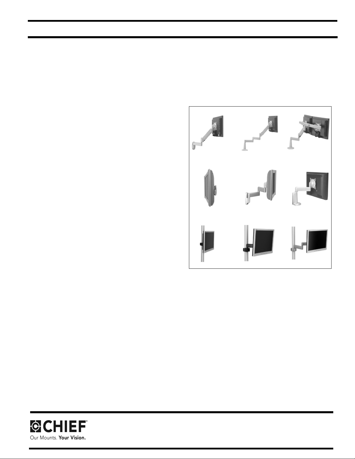
This Instruction Manual covers most of the K-Series wall,
desk, and pole mounts for single , dual, and triple
displays. In addition, this Instruction Manual also covers
selected K-Series accessories.
NOTE: Some K-Series moun ts, such as Extreme Tilt,
Grommet, and Table, as well as most K-Series
accessories, have separate Instruc tion Manuals.
See Specifications for a complete list of models
covered by this Instruction Manual.
NOTE: If an accessory such as an optional laptop tray is
being installed, complete all required installation
procedures within this document prior to installing
the accessory.
K-Series Mounts (Examples)
Chief Manufacturing, a products division of
Milestone AV Technologies
6436 City West Parkway, Eden Prairie, MN 55344
• P: 800.582.6480 / 952.225-6000 • F:877.894.6918 / 952.894.6918
8800-002338 Rev.00
©2013 Milestone AV Technologies, a
Duchossois Group Company
www. chiefmfg.com
04/13
Model: K-Series Installation Instruc tions
DISCLAIMER
Milestone AV Technologies and its affiliated corporations and
subsidiaries (collectively "Milestone"), intend to make this
manual accurate and complete. However, Milestone makes no
claim that the information contained herein covers all details,
conditions or variations, nor does it provide for every possible
contingency in connection with the installation or use of this
product. The information contained in this document is subject
to change without notice or obligation of any kind. Milestone
makes no representation of warranty, expressed or implied,
regarding the in formation cont ai ned her ein. Mil estone assu mes
no responsibility for accuracy, completeness or sufficiency of
the information contained in this document.
Chief® is a regist ered t rademark of Mil estone AV Te chnologies .
All rights reserved.
IMPORTANT SAFETY INSTRUCTIONS
WARNING: A WARNING alerts you to the possibility of
serious injury or death if you do not follow the instructions.
CAUTION: A CAUTION alerts you to the possibility of
damage or destruction of equipment if you do not follow the
corresponding instructions.
WARNING: Use this mounting system only for its intended
use as described in these instructions. Do not use
attachments not recommended by the manufacturer.
WARNING: Never operate this mounting system if it is
damaged. Return the mounting system to a ser vice cen ter for
examination and repair.
WARNING: Do not use this product outdoors.
--SAVE THESE INSTRUCTIONS--
WARNING: Failure to read, thoroughly understand, and
follow all instructions can result in serious personal injury,
damage to equipment, or voidi ng of f actory wa rrant y! It i s the
installer’s responsibility to make sure all components are
properly assembl ed and installed using the instructions
provided.
WARNING: Failure to pr ovide adequate structural strength
for this component can result in serious personal injury or
damage to equipment! It is the installer’s responsibility to
make sure the structure to which this component is attached
can support five t imes t he combi ned wei ght of al l eq uip ment.
Reinforce the structure as required before installing the
component. The wall to which the mount is being attached
may have a maximum drywall thickness of 5/8" (1.6cm). Do
not install drywall anchors into the seam between drywall
pieces.
WARNING: Exceeding the weight capacity can result in
serious personal injury or damage to equipment! It is the
installer’s responsibility to make s ure the combined weight of
all components located between the K-Series mount up to
(and including) the display does not exceed the weight limit
listed in Table 1.
2

Model: K-Series Installation Instruc tions
CONTENTS
TOOLS REQUIRED FOR INSTALLATION ...............................................................................................................3
SPECIFICATIONS.....................................................................................................................................................4
MOUNT INSTALLATION........................................................................................................................................... 5
DISPLAY INSTALLATION........ ......... .......... ......... ......... .......... ......... .......... ......... .......... ......... .......... ......... ............ ....8
ARRAY ASSEMBLY (DUAL / TRIPLE DISPLAY; ALL EXCEPT KCY-210/-220)..................................................... 10
MULTI-DUAL ARM ASSEMBLY (KCY-210/-220 ON LY)............................................................ ..............................11
CABLE MANAGEMENT..........................................................................................................................................12
ADJUSTMENT........................................................................................................................................................ 13
TOOLS REQUIRED FOR INSTALLATION
• Phillips Screwdriver, #1 and #2
• 9/16" Wrench (KSA-1015/-1016 Only)
• Drill (All Wall Mounts)
• 1/8" Drill Bit (All Wall Mounts except KSA-1015/-1016)
• 1/4" Drill Bit (KSA-1015/-1016 Only)
• 2.5mm Hex Key (approximately 3/32"; provided with Desk Mounts)
• 5/32" Hex Key (provided with applicable K-Series mounts)
• 3/16" Hex Key (provided with all K-Series mounts)
NOTE: Other tools may be required depending on your method of installation.
3
Installation Instructions Model: K-Series
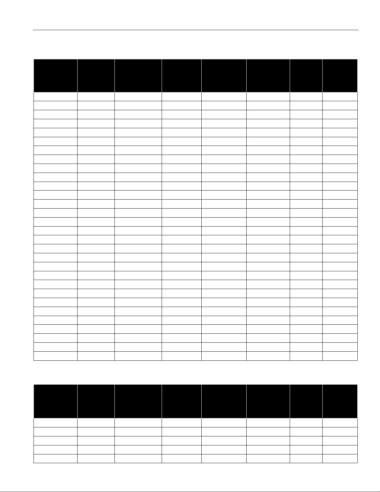
SPECIFICATIONS
Table 1: Mounts
MODEL NO. OF
DISPLAYS
SUPPORTING
STRUCTURE
NO. OF
MOUNTING
ARMS
ADJUSTABLE
HEIGHT
MAX.
EXTENSION
(INCHES)
MIN.
CLOSED
DEPTH
(INCHES)
KWP-110 Single Wall None No None 2.9 40
KWV-110 Single Wall Single Yes 13 2.2 25
KWS-110 Single Wall Single No 9.5 2.2 40
KWG-110 Single Wall Dual Yes 19.5 2.2 25
KWD-110 Single Wall Dual No 16 2.2 40
KWB-110 Single Wall Triple Yes 26 2.2 25
KCV-110 Single Desk Single Yes 13.5 2.2 25
KCS-110 Single Desk Single No 10 2.2 40
KCG-110 Single Desk Dual Yes 20 2.2 25
KCD-110 Single Desk Dual No 16.5 2.2 40
KCB-110 Single Desk Triple Yes 26.5 2.2 25
KPP-110 Single Pole None No None 2.2 40
KPS-110 Single Pole Single No 9.5 2.2 40
KPD-110 Single Pole Dual No 16 2.2 40
KPG-110 Single Pole Single Yes 16.5 2.2 25
KPV-110 Single Pole Single Yes 13.3 2.2 25
KWD-130 Single Wall Single Yes 18.6 5.1 25
KWS-220 Dual Wall Single No 13.5 6.4 17
KWD-220 Dual Wall Dual No 20 6.4 17
KCS-220 Dual Desk Single No 14 6.4 40
KCD-220 Dual Desk Dual No 20.5 6.4 17
KCY-210 Dual Desk Multi-Dual Yes (one arm) 20 2.2 20
KCY-220 Dual Desk Multi-Dual Yes (two arms) 20 2.2 20
KWD-230 Dual Wall Single No 18.6 5.9 40
KWS-320 Triple Wall Single No 13.5 6.4 10
KWD-320 Triple Wall Dual No 20 6.4 10
KCS-320 Triple Desk Single No 14 6.4 10
KCD-320 Triple Desk Dual No 20.5 6.4 10
KGL-110 Tray Desk Single Yes 29.5 14 18
KGL-220 Single/Tray Desk Dual Yes 29.5 14 40 total
MAX.
SUPPORT
WEIGHT
(LBS.)
PER MONITOR
Table 2: Accessories
MODEL NO. OF
MONITORS
SUPPORTING
STRUCTURE
NO. OF
MOUNTING
ARMS
ADJUSTABLE
HEIGHT
MAX.
EXTENSION
(INCHES)
MIN.
CLOSED
DEPTH
(INCHES)
KMA-220 Dual N/A N/A N/A N/A N/A 17
KMA-320 Triple N/A N/A N/A N/A N/A 10
KMA-325 Triple N/A N/A N/A N/A N/A 10
KSA-1015 N/A Wall Single No 16 6.4 75
KSA-1016 N/A Wall Dual No 24.5 6.4 75 total
MAX.
SUPPORT
WEIGHT
(LBS.)
PER MONITOR
4
Installation Instructions Model: K-Series
MOUNT INSTALLATION
INSTALLATION TO WALL
1. Verify that you have the following parts:
Item Description Qty
10 MOUNT, Wall, K-Series 1
20 BRACKET, Wall 1
30 SCREW, Hex Head Lag, 1/4" x 2-1/2"
(ALL EXCEPT KSA-1 015/-1016)
40 SCREW, Hex Head Lag, 3/8" x 3"
(KSA-1015/-1016 ONLY)
50 WASHER, Flat Machine Screw, 1/4"
(ALL EXCEPT KSA-1 015/-1016)
2. Determine location for mount keeping in mind display
size, extension, height adjustment (if applicable), and
pitch/roll requirements. Bracket (20) MUST be
installed into wood stud.
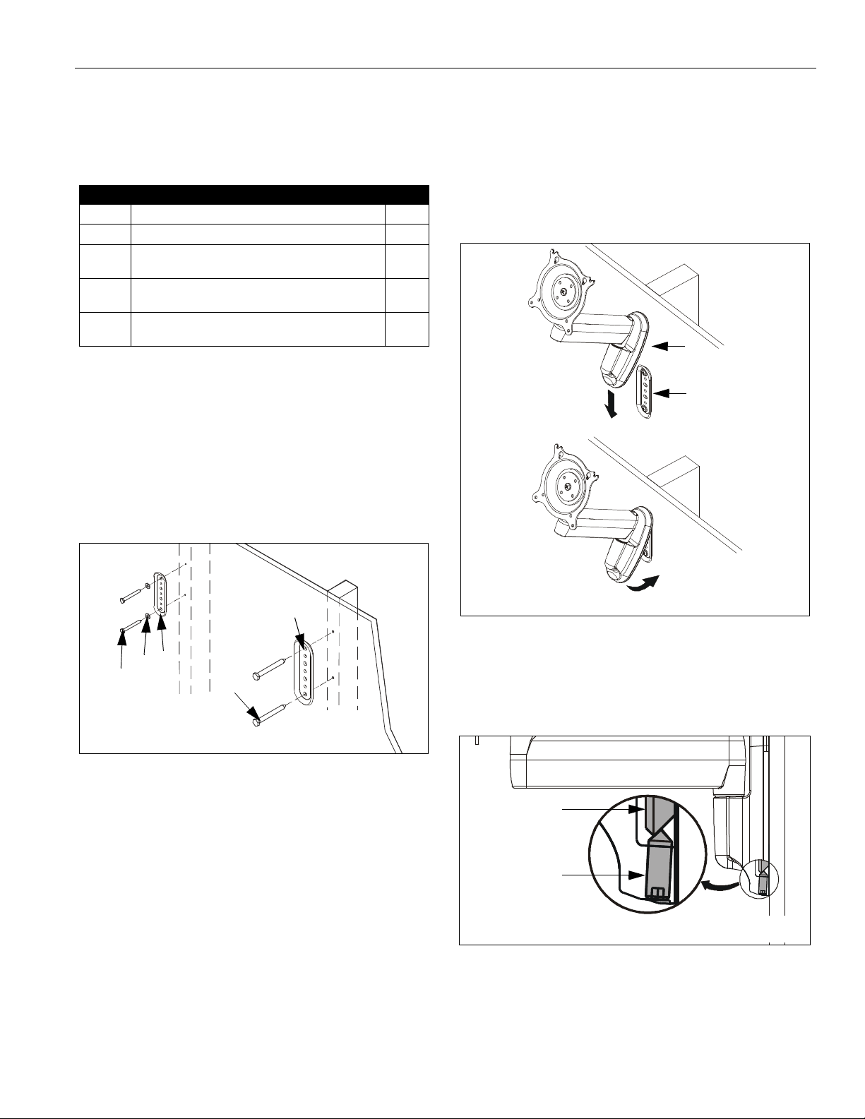
3. Using bracket (20) as a template, drill two pilot holes
through top and bottom holes of bracket (20) into wall
structure (See Figure 1):
• All Except KSA-1015/-1016: Use 1/8" drill bit
• KSA-1015/-1016 ONLY: Use 1/4" dri ll bit
2
2
2
IMPORTANT ! : IF you will be installing a SINGLE
display with RECESSED mounting holes, then proceed
to "DISPLAY INSTALLA TION "before continuing with this
mount installation procedure.
5. Insert top of mount (10) over lip on top of bracket (20)
(See Figure 2). Swing mount (10) down flush against
wall.
10
20
20
20
50
30
40
All except
KSA-1015/-1016
KSA-1015/-1016
Figure 1: Install Wall Bracket
4. Install bracket (20) (See Figure 1):
• All Except KSA-1015/-1016:
Using 7/16" wrench, install screws (30) through
washers (50), plate (20), and drywall into wood
stud. Ensure bracket (20) is vertical, then tighten
screws (30).
• KSA-1015/-1016 ONL Y:
Using 9/16" wrench, install screws (40) through
plate (20) and drywall into wood stud. Tighten
screws (40).
IMPORTANT ! : Overtightening screws (30 or 40, as
applicable) may cause bracket (20) to compress into soft
wall surface, resulting in difficult mount installation or
improper engaging of set screw in step 6.
NOTE: KWS-110 shown; other wall mounts similar.
Figure 2: Install Wall Mount
6. Tighten set screw using 5/32" hex key (See Figure 3).
Ensure set screw engages back side of bracket (20)
to properly secure mount.
20
Set Screw
NOTE: KWS-110 shown; other wall mounts similar.
Figure 3: Tighten Set Screw
7. Proceed to "CABLE MANAGEMENT" (for SINGLE
display with RECESSED mounting holes), or to
"DISPLAY INSTALLATION" (for all other display
configurations).
5
 Loading...