

CHIAYO ADVENTURE 800 User Manual
GOO D DESIG N
PRO DUCT
GREEN PRODUCT
It has been RoHS Compliant
Portable Sound System
OPERATION MANUAL
CHIAYO ELECTRONICS CO., LTD.
http://www.chiayo.com.tw E-mail: sales@chiayo.com.tw
OFFICE: 30, LANE 27, SEC.4. JEN-AL ROAD, TAIPEI, TAIWAN / TEL: 886-2-2741-5741 FAX: 886-2-2752-5242
FACTORY: 88, CHUNG HSIAO STREET 2, CHIAYI, TAIWAN. / TEL: 886-5-271-1000 FAX: 886-5-276-7611
Printed in Taiwan, April 2008
12I1151
CHIAYO ELECTRONICS CO.,LTD
General
Congratulation for owning this all-in-one portable sound system. Please read this operating
instruction thoroughly to fully understand its controls and functions.
There are 4 versions of Adventure 800, namely the
(1). Adventure 800 with Tape Deck. ( Fig. 1 )
(2). Adventure 800 with CD / USB Player. ( Fig. 2 )
(3). Adventure 800 with CD / USB Player & Digital Recorder. ( Fig. 3 )
(4). Adventure 800 with CD / USB Player & Tape Deck. ( Fig. 4 )
(5). Adventure Companion Speaker only (WA-517). ( Fig. 5 )
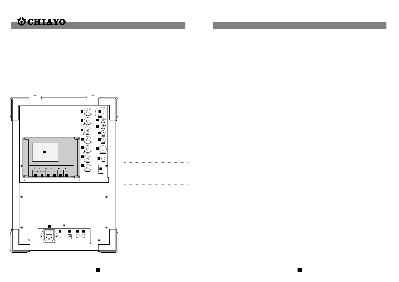
Adventure 800 with Tape Deck
1. MIC IN (BALANCE/UNBALANCE)
2. WR1 channel selector
3. WR2 channel selector
4. AUX IN
5.AUX OUT
6.MASTER VOLUME
7.FUSE
8.POWER (ON / OFF)
9.MIC
10.WR1 VOLUME
11.WR2 VOLUME
12.AUX VOLUME
13.TAPE VOLUME
14.BASS
15.TREBLE
16.AC INPUT JACK / FUSE
17.BATTERY STATUS INDICATOR
18.DC 24~32V INPUT
19.SPK OUT
20.SPK OUT (SWITCHED)
21.CASSETTE COVER
22.
RECORD KEY
23.
PLAY KEY
24.
FAST REWIND KEY
25.
FAST FORWARD KEY
26.
STOP/EJECT KEY
27.
PAUSE KEY
21
REC PLAY F.FREW ST/EJ PAUSE
26
25
24
23
22
TREBLE
1
2
CH
3
CH
4
5
6
MASTE R
7
BASS
FUSE
8
9
10
11
12
13
14
15
27
FCC Caution:
To assure cont inu ed co mpl iance, any changes or modif ica tio ns no t exp ressly
approved b y the p art y res pon sible for compliance coul d avo id th e use r's authority
to operate this e qui pme nt. ( Example - use only shielded i nte rfa ce ca ble s when
connecti ng to c omp ute r or pe ripheral devices.
This devic e com pli es wi th Pa rt 15 of the FCC Rules. Operati on is s ubj ect t o the
followin g two c ond iti ons :
(1)This de vic e may n ot ca use h armful interference, an d
(2)this de vic e mus t acc ept a ny interference receive d, in clu din g interference that
may cause un des ire d ope ration.
16
17 18 19 20
Fig. 1
1
30
Maintenance-free Lead Acid battery
Guidelines for maintenance-free Batteries:
1. Battery should operate at temperatures between 15°C ~ 50°C. To ensure a longer life span, it
should be kept between 5°C ~ 35°C. For optimum result, 20°C ~ 25°C will be ideal. When
temperature falls 15 degrees below zero, battery will undergo some changes in its chemical
contents and therefore cannot be recharged. Operating the battery at higher temperature will
result in higher capacity but shorter lifespan, whereas lower temperatures operation has a
longer lifespan but less capacity.
2. If the battery is not recharged 72 hrs after it is completely used, it will be permanently damaged.
3. When the battery is being charged, the internal gases will be electrolyzed into water at the
negative charge, maintaining the battery’s storage abilities with no water added. However,
erosion at the charged ends of the battery will cause poor performance.
4. The battery’s cycle lifespan ( no. of charge and discharge cycle ) is determined by the degree at
which power is dissipated., especially the degree of discharged each time it is used and the
recovery charging method. For normal use, the battery can be used for longer hours when less
power is dissipated each time and vice versa. At 25°C, maintenance-free batteries could be
charged 150 ~ 200 times at 100% discharge each time.
5. Decrease in capacity, internal short circuit, deformation in appearance, erosion of charged ends
and decrease in open circuit voltage are symbols indicating battery is approaching the end of its
life cycle.
6. When two batteries are used in parallel connection, the resistance of the cables should be kept
equal.
Properties of the Lead Acid Battery:
1. Has no memory effect. Can be charged at anytime, even when the recharge indication light is
not on.
2 .Performance and efficiency are affected by changes in the environment, especially temperature
and humidity. (Best operated between 20°C ~ 25°C)
3. Battery discharge naturally according to a certain pattern even not in use. For best performance
and a prolonged lifespan, it should be recharged every month even when not in use.
4. Under normal circumstances, battery could last for about a year.
5. When the battery’s life expires, possible indicators include internal short-circuit, decrease in
capacity, deformation in appearance, erosion of charged ends and decrease in operating
voltage.
User’s Precautions:
1. For first-time use, charge the battery for 10 hrs until it is fully charged.
2. To maintain performance and lifespan, if product has not been used for 3 months after the
initial shipment, please fully charge the battery.
3. Before each use, it’s advisable to charge the battery to its full capacity.
4. The average lifespan of the battery is one year. The user is advised to change the battery after
one year of use.
5. The current consumption is in direct ratio with load current. The more current consumption, the
less the operation time.
6. SMART and FOCUS operate on one 12V/2.7AH battery. ADVENTURE, CHALLENGER, and
VICTORY operate on two 12V/4.5AH batteries.
29
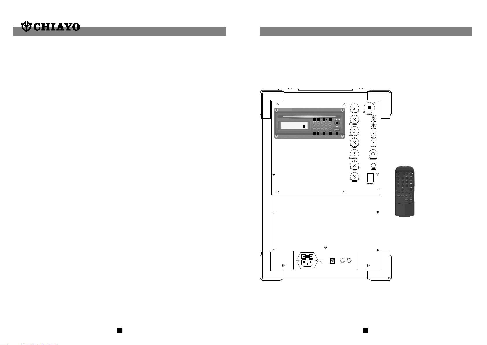
Rear panel configuration ( CD / USB Player )
1. LCD Display
2. PLAY/PAUSE
1
C
D
B
E
H I
K
J
A
G
F
TREBLE
CH
CH
MASTE R
BASS
FUSE
Fig. 2
2
3. STOP
4. SKIP
5. EJECT
6. CD SELECTOR
7. USB SELECTOR
8. FOLDER SKIP
9. IR LED
10. USB INPUT
11. POWER/VOL.
CD player
remote control.
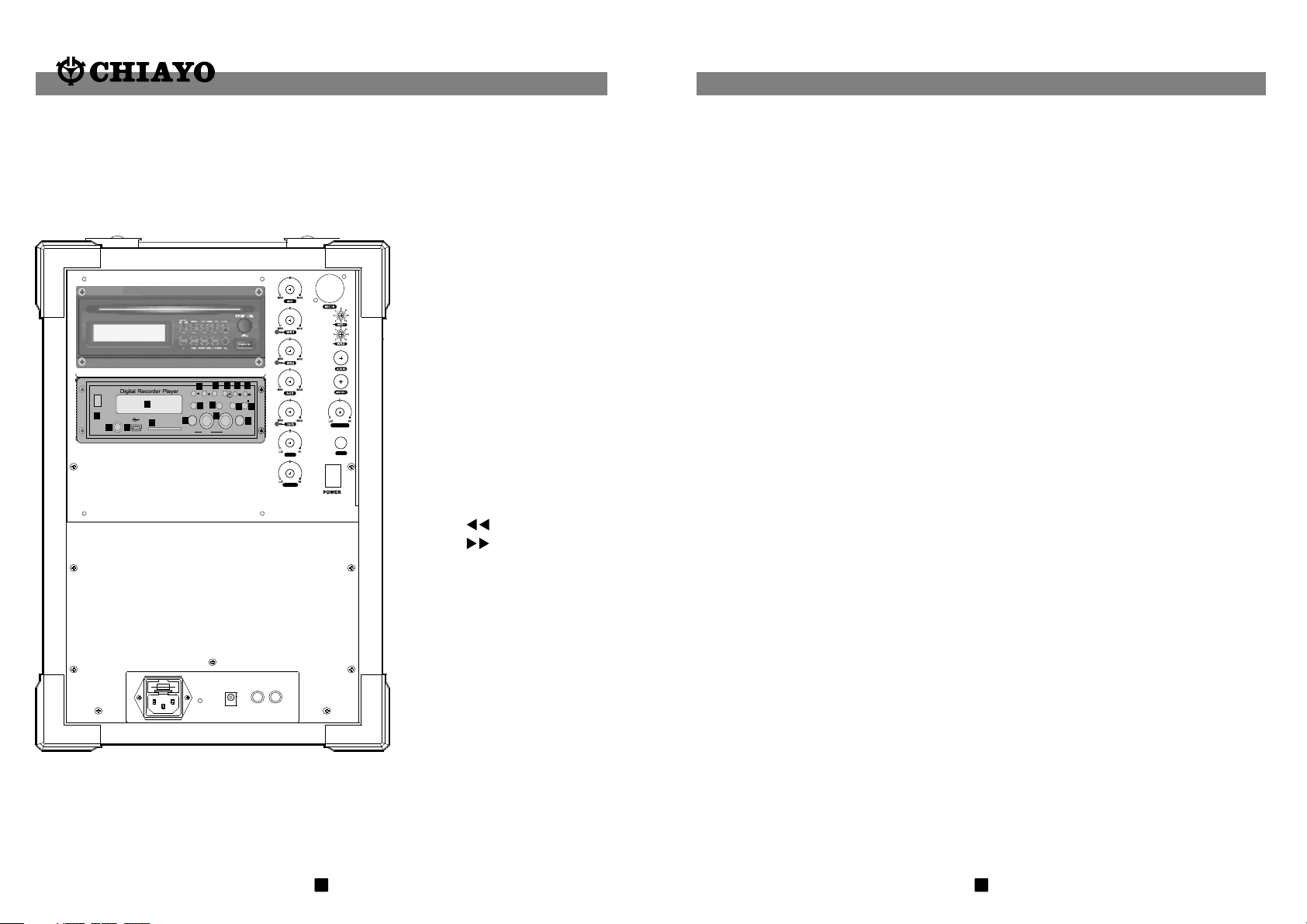
Adventure 800 with CD / USB Player & Digital Recorder
CH
CH
g
j
h
i
f
LINE EQ
VO/M3 DEL.
A-B
REC
MODE
STOP
POWER
a
b
EAR
c
d
o
SD card
e
MIC
VOL
PLAY
l
k
m
n
F
C
p
q
MIC IN
VOL
RL/L+R
TREBLE
MASTE R
BASS
FUSE
a. POWER
b. LCD Display
c. EAR
d. USB
e. SD Card Slot
f. LINE▲▼
g. EQ
h. REPEAT
i.
j.
k. REC
l. STOP
m. MODE.
n. PLAY ll
o. MIC VOL
p. MIC IN
q. VOL
Input Level Gain Control Adjustment
Low impedance ( Lo-Z ) " MT" & high impedance ( Hi-Z ) " GT" gain controls are situated
inside the transmitter as shown in Fig 10. Gain controls are adjustment ports that enable
you to use microphones of differing output levels and Guitar or instruments with Hi-Z output.
To adjust microphone ( Lo-Z ) input levels, turn the " MT" control and to adjust the Guitar or
instrument ( Hi-Z ) input, adjust the " GT" gain control to set the transmitter's desired audio
input level.
Caution and tips on how to obtain the best results
1.Before inserting the batteries, please make sure that they are inserted according to the
correct polarity.
2.For PLL-16-frequency agile version, before operation please make sure that the
corresponding receiver MUST have the same frequency group and channel number as the
transmitter.
3.For fixed frequency version, before operation please make sure that corresponding
receiver MUST have the same frequency as the transmitter.
4.Before making any channel change, please switch off the power supply. The synthesized
program works in such a way that a change of channel will only take place after a power off
and on action. Otherwise, the previously selected frequency will stay unchanged.
5.After making a channel change, please make sure that the corresponding change is made
on the matching receiver also. To be exact, changes MUST be made at both the transmitter
and receiver.
6.The audio cable of M-1002 and SM-916 also serve as antenna. The length of the cable is
cut according to the specific frequency range. Do not alter the length or mix around the
cable of different transmitters. The use of wrong audio cable will affect the antenna
efficiency of the transmitter!
7.Use only brand new Alkaline batteries. Do not use " general purpose " batteries. When
batteries are weak, replace the three batteries altogether at the same time. Do not mix and
use new and old batteries together.
8.Position the receiver such that it has the least possible obstructions between it and the
transmitter. Line of sight is best!
9.The transmitter and the receiver should be as close as possible but not less than 1m.
10.A receiver cannot receive signals from two or more transmitters simultaneously.
11.Turn the transmitter off when it is not in use. Remove the batteries if it is not to be used
for a period of time.
Fig. 3
3
28
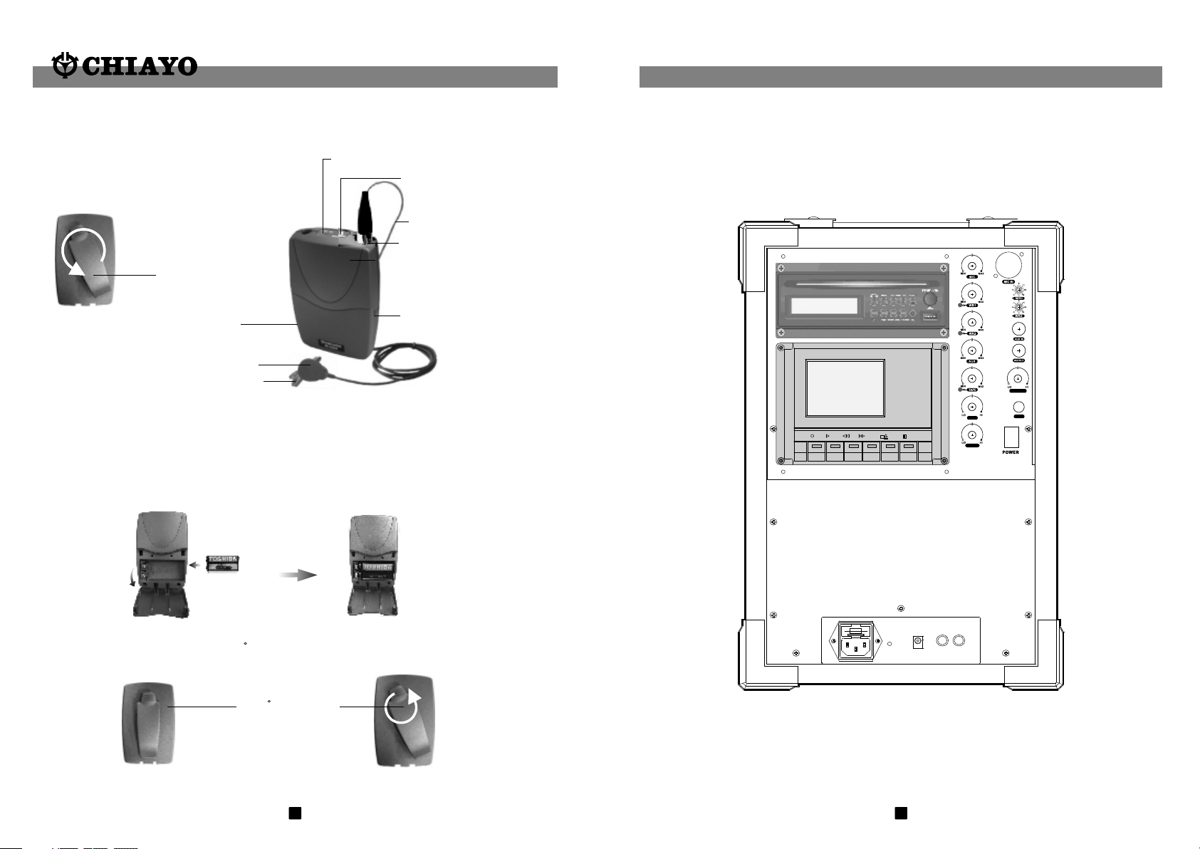
VHF Belypack Transmitter M-1002
Par ts & Fu nction s
Belt clip
( hidden behind )
Battery
compartment
MIC capsule
MIC clip
Power Switch
Battery st atus
indicator.
MIC cable
MIC IN socket
Battery compartment
cover
Adventure 800 with CD / USB Player & Tape Deck
CH
CH
MASTE R
Battery Installation
M-1002 uses 1 piece of 9V battery. To install new or replace the old battery, first open the
battery compartment cover, then insert the new battery according to its correct polarity as
indicated. For longer operation hour, Alkaline battery is recommended!
Fig.11
Belt Clip
This uniqu ely d esi gne d belt clip allows 360 rotati on. S ele ct th e best position to achieve
optimum weari ng co mfo rt.
360 ro tate ab le
belt c lip.
Fig.12
27
REC PLAY F.FREW ST/EJ PAUSE
Fig. 4
4
TREBLE
BASS
FUSE
 Loading...