

Cherry GH-703 Maintenance Manual
GH-703
MAINTENANCE MANUAL
Power Riveter
1224 East Warner Ave,
Santa Ana, CA 92705
Tel: 1-714-545-5511
Fax: 1-714-850-6093
www.cherryaerospace.com
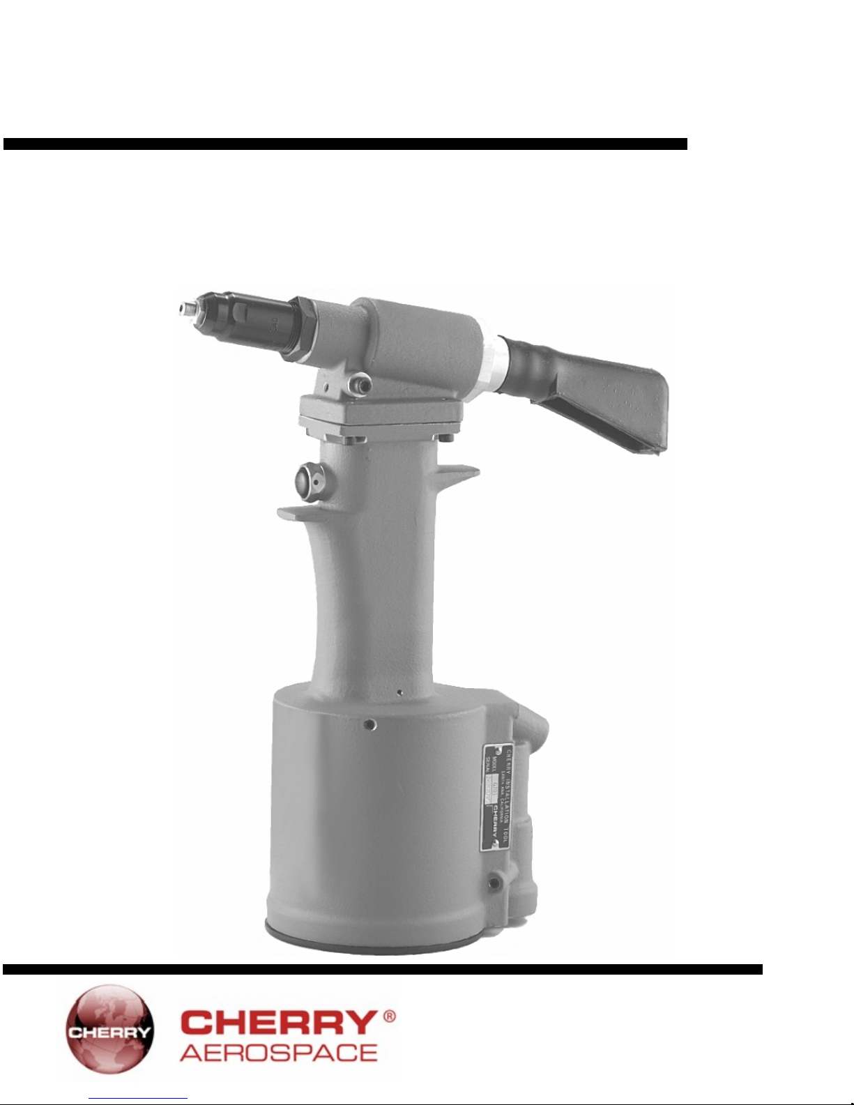
Power Riveter
The Cherry® GH-703 is a pneumatichydraulic tool designed specif ically for the most
efficient installation of commercial fasteners. It
weighs only 5 pounds and can be operated in
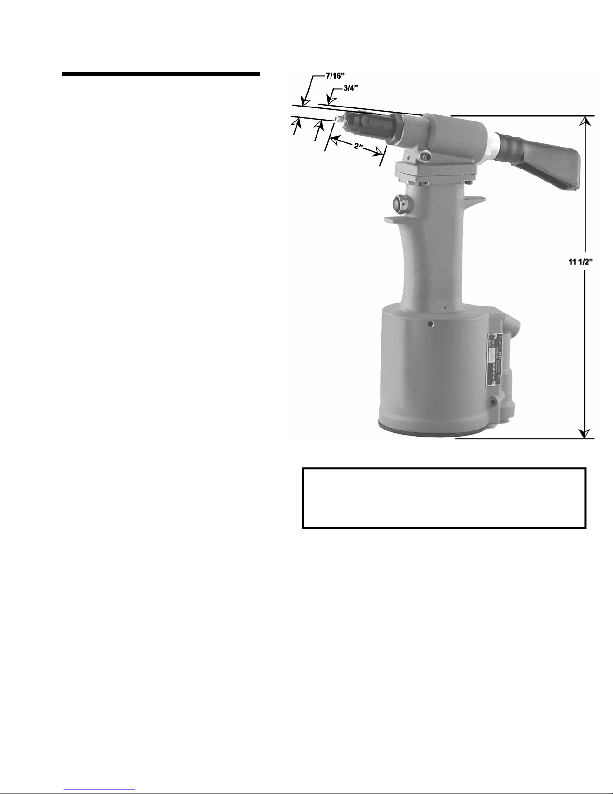
any position with one hand. It has a full 3/4”
rivet setting stroke and a rated pull load of 2000
pounds.
The GH-703 riveter operat es on a wide range of
air pressure, with 90 to 120 psi providing the
maximum efficiency. At 90 lbs. air pressure, the
GH-703 has a decibel rating of 80dB(A) and
consumes 3 CFM at 20 cycles per minute.
A mandrel catcher bag may be attached to
eliminate costly cleanup.
G H-703
The GH-703 comes equipped with nosepiece 728A9-6 to set:
N Rivets - 3/16” diameter
Q Rivets - 3/16” diameter
Cherrymate
® Rivets - 1 /4” diameter
There is also a spare nosepiece, 728A9-4,
included for setting:
N Riv et s - 1 /8 ” dia m ete r
Q Riv et s - 1 /8 ” dia me te r
Cherrymate
® Rivets - 3/16” diameter
Warning: Approved eye protection
should be worn when operating, re-
pairing, or overhauling this tool.
MANY OTHER STYLES AND SIZES OF COMMERCIAL RIVETS CAN BE SET WITH THIS
TOOL. REFER TO THE NOSEPIECE SELECTION CHART ON PAGE 8 FOR APPLICABLE
PART NUMBERS.
1
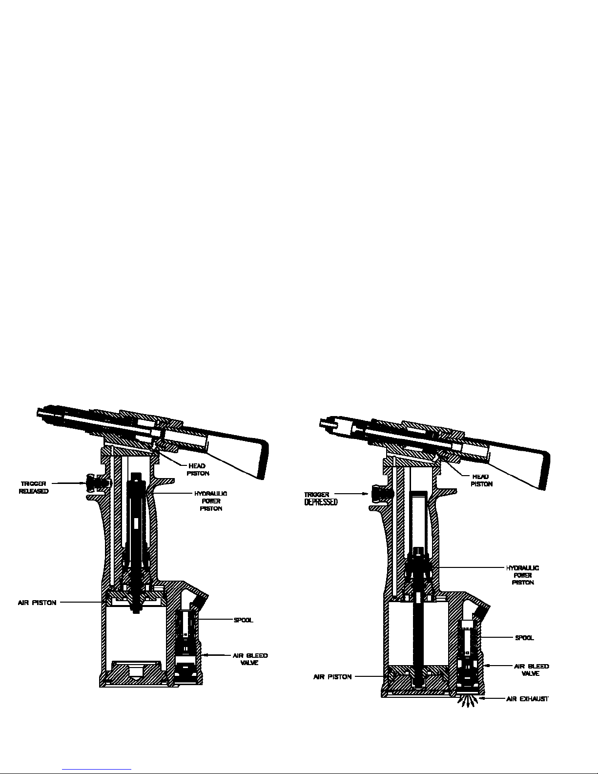
How the GH-703 Operates
When the tool is pressurized by hooking up to an
air line, the valve spool is forced upward. This
movement aligns the port in the spool with the lower
port within the handle, allowin g air pressure to enter
the bottom port of the power air cylinder. This forces
the air piston upward.
When the trigger is depressed, air bleeds out from
behind the trigger, lowering air pressure against the
bottom of the s pool. Air pres sure is no w greater on
top of the spool, forcing it down. This action shuts
off the air path to the bottom of the power air cylinder,
and simultaneously opens the upper port, allowing
pressure to enter directly into the top of the air
cylinder. This forces the air piston downward.
The air piston is connected to the hydraulic power
piston with a common connecting rod. When the
air piston is activated by changes in the air valve,
it in turn activates the hydraulic power piston. Air
pressure also travels up through a port in the handle
to enter the rear of the head cylinder. This air
pressure forces the return of the head piston to its
full forward position.
The center area of the ha ndle (that part held by the
hand during riveting) contains the hydraulic system.
The hydraulic power piston has its own cylinder
containing the fluid which is pressurized by the
downward travel of the piston. This forc es the fluid
up through the handle into the front of the head
cylinder, thereby exerting the force needed to push
the head piston back in a full 3/4” rivet setting stroke.
This same fluid then returns to the power cylinder
by the forward action of the head piston under air
pressure.
SPECIFICATIONS ARE SUBJECT TO CHANGE WITHOUT NOTICE.
2
 Loading...