

Page 1
User Manual
Page 2

TABLE OF CONTENTS
1. Before You Begin ...........................................................................................................4
What Is Included ........................................................................................................................ 4
Unpacking Instruc tions ............................................................................................................... 4
Claims .............................................................................................................................................. 4
Text Conventions ....................................................................................................................... 4
Symbols ..................................................................................................................................... 4
Disclaimer .................................................................................................................................. 4
Product at a Glance ................................................................................................................... 4
Safety Notes .............................................................................................................................. 5
2. Introduction ....................................................................................................................5
Features .................................................................................................................................... 5
Additional Features .................................................................................................................... 5
Product Overview ....................................................................................................................... 6
Product Overview (cont.) ................................................................................................................... 7
Common Terms ......................................................................................................................... 8
Product Dimensions ................................................................................................................... 8
3. Operating Instructions ...................................................................................................9
DC Power .................................................................................................................................. 9
Setup ......................................................................................................................................... 9
Page Selection ........................................................................................................................... 9
Master Faders .......................................................................................................................... 10
Crossfade Mode .............................................................................................................................. 10
Chase◄►Scene Mode ................................................................................................................... 10
Channel Mode ................................................................................................................................. 10
4. Record Mode ................................................................................................................11
Enable Record ......................................................................................................................... 11
Create a Scene ........................................................................................................................ 11
Playing a Scene ....................................................................................................................... 11
Record Clear ............................................................................................................................ 11
5. Edit Mode ......................................................................................................................12
Enable Edit .............................................................................................................................. 12
Delete a Scene ........................................................................................................................ 12
Delete a Step or Steps ............................................................................................................. 12
Insert a Step or Steps .............................................................................................................. 12
Modify a Step or Steps ............................................................................................................. 12
6. Playback Options .........................................................................................................13
Audio Triggering....................................................................................................................... 13
Speed ...................................................................................................................................... 13
Show Mode ..................................................................................................................................... 13
Beat Mode ...................................................................................................................................... 13
Speed Modes .................................................................................................................................. 14
Fade ........................................................................................................................................ 14
Single Chase Mode .................................................................................................................. 14
Mix Chase Mode ...................................................................................................................... 14
7. Other Functions............................................................................................................15
Black Out ................................................................................................................................. 15
Dark ......................................................................................................................................... 15
Hold ......................................................................................................................................... 15
Blind and Home ....................................................................................................................... 15
Page 2 of 20 Stage Designer 50 User Manual Rev. 11
Page 3

Reverse Functions ................................................................................................................... 15
% or 255 .................................................................................................................................. 15
Add Kill .................................................................................................................................... 15
Full On ..................................................................................................................................... 15
Master Reset ........................................................................................................................... 15
Auxiliary Cont r ols ..................................................................................................................... 16
MIDI Operation......................................................................................................................... 17
Settin g MIDI In/Out .......................................................................................................................... 17
MIDI Control Chart .......................................................................................................................... 17
MIDI File Dump ............................................................................................................................... 17
8. Techni cal Sp ecificatio ns ..............................................................................................18
Returns .............................................................................................................................19
Contact Us ........................................................................................................................20
Stage Designer 50 User Manual Rev. 11 Page 3 of 20
Page 4
What Is
Included
Stage Designer 50
• User Manual
Unpacking
Instructions
Carefully unpack the product immediately and check the container to make sure all the parts
If the b ox or the cont ents (the pr oduct and incl uded accesso ries) appear damaged from
For ot her i ssu es, suc h as m i ssing com pon ents or p ar ts, dam age n ot r el at ed to shipping, o r
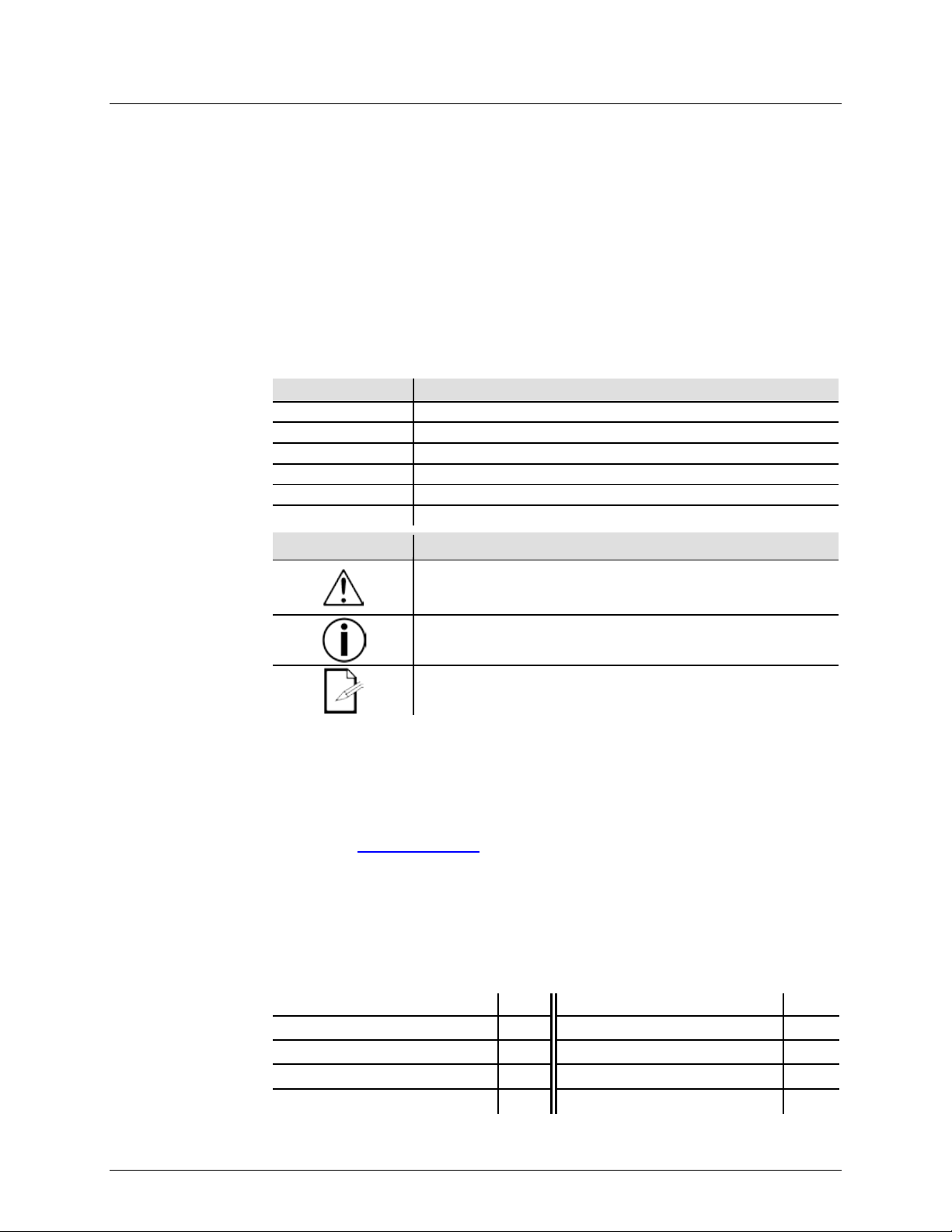
Text
1—512
A range of values
50/60
A set of values of which only one can be chosen
Settings
A menu option not to be modified
Menu > Settings
A seq uence of menu o ptions to be fol lowed
<ENTER>
A key t o be pres sed on t he product’s control panel
ON
A value to be enter ed or selected
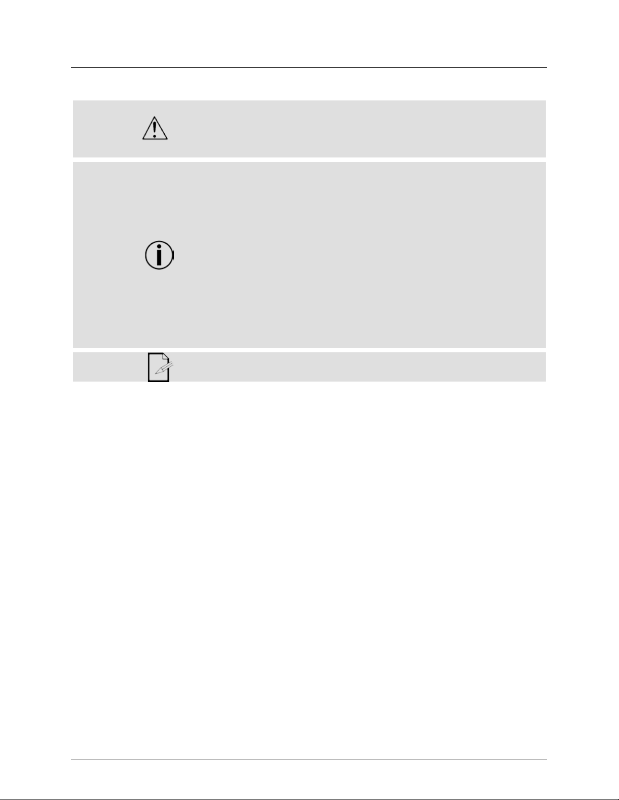
Symbols
Critical installation, configuration, or operation informa tion. No t
damage to the product, or cause harm to the operator.
Disclaimer
Chauv et believ es that t he inform ation cont ained i n this m anual is ac curate i n all r espects.
any party for any l oss, damage or di sruption caused by any error s or omissions i n this
t or any other
cause. Chauvet reserves the right to revise the content of this document without any
obligation to notify any person or company of such revision, however, Chauvet has no
wnload t he l at est
The works of authorship contained in this manual, including, but not limited to, all design,
Stage Designer 50 are registered trademarks or
trademarks of their respective companies.
Product at a
x
x
x
P
P
x
P
x
x
1. BEFORE YOU BEGIN
•
• External Power Supply
are in the package and are in good condition.
• Warranty Card
Claims
Conventions
shipping, or show signs of mishandling, notify the carrier immediately, not Chauvet. Failure to
report damage to the carrier immediately may invalidate your claim. In addition, keep the box
and contents for inspection.
concealed damage, file a claim with Chauvet within 7 days of delivery.
Convention Meaning
Symbol Meaning
following these instructions may make the product not work, cause
Important installation or configuration information. The product
may not function correctly if this information is not used.
Useful information.
However, Chauvet assumes no responsibility and specifically disclaims any and all liability to
docum ent, w hether s uch errors or om ission s r esult fr om neglig ence, accid en
oblig ati on t o m ak e, and do es not c ommi t to make, any s uch r ev isi ons. Do
version from www.chauvetdj.com.
text and images are owned by Chauvet.
© Copyright 2018 Chauvet & Sons, Inc. All rights reserved.
Electronically published by Cha uvet in t he Unit ed States of Americ a.
CHAUVET, the Chauvet logo, and
trademarks of Chauvet & Sons Inc. (d/b/a Chauvet and Chauvet Lighting) in the United States
and other countries. Other company and product names and logos referred to herein may be
Glance
Page 4 of 20 Stage Designer 50 User Manual Rev. 11
Use on Dimmer
Out door Use
Sound-Active
DMX
Master/Slave
Auto Programs
Auto-ranging Power Supply
Replaceable Fuse
User-Serviceable
Page 5
Safety Notes
Please read the following Saf et y Notes careful ly before working with the product. The Notes
include important safety information about installation, usage, and maintenance.
Always connect the product to a grounded circuit to avoid the risk of electrocution.
• Make sure t here ar e no flammable materi als close to the product when operating.
completely dis connect the product f rom pow er via breaker or by unplugging it.
2. INTRODUCTION
The Stage Designer 50 is a univ ersal intelligent li ghting controller. It allows the control of
It also has an LCD display for easy navigation of controls and menu functions.
Features
playback)
• 48,000 programmable steps
Additional
• 3-pin and 5-pi n DMX connections
playback of chases
• Override chases on the fly
•
• Always disconnect the product from the power source before cleaning.
• Make sure the power cord is not crim ped or damaged.
• Never disconnect the product from power cord by pulling or tugging on the cord.
• The product is not intended for permanent installation.
• Always make sure that the voltage of the outlet to which you are connecting the
product is within the range stated on the decal or rear panel of the product.
• The product is for i ndoor use only ! ( IP20) To prevent ri sk of fire or sho ck, do n ot
expose the product to rain or moisture.
• Always install the product in a location wit h adequate ventilation, at least 20 in
(50 cm) from adjacent surfaces.
• Never connect the product to a di mmer or rheostat.
• Never carry the product from the power cord.
• The maximum ambient t emperature (Ta) is 104 °F ( 40 °C). Do not operate the
product at higher temperatures.
• In the event of a serious operating probl em, stop using the product immediately.
• Never try t o repair the product. Repairs carried out by unskilled people can l ead to
damage or malfuncti on. Please contact the nearest authorized technical assistance
center.
• To eliminate unnecessary wear and improve its lifespan, during periods of non-use
Keep this User Manual for future use. If you sell the product to someon e else, be
sure that they also receive th i s document.
48 channels with 24 fader s . Eac h scen e/c has e ca n con tai n up t o 1,000 individual steps,
or looks. When in playback mo de, th ere are 12 p hysic al fader s for t he play back of the
saved pro grams. There are 4 pages of scenes to play back on Page A, and an additional
4 pages of scenes to play back on P age B. Progr ams can be tri gg ered b y musi c, mi di,
automatically or manually. The product has various programming tools such as A/B
maste r fa d ers for live control, an d Fade and Speed time faders for on the fly ad just men ts .
• 48-channel DMX-512 dimming console
• 2 programmable aux buttons
• Adjustable chase and fade times
• Beat-activation, tap sync, auto run,
midi in/out
• 6-space (6 U) rack mount
• Polarity selector
Features
• 4 pages with 12 scenes each yiel ds 48
total playback faders (simultaneous
• Built-in cros s-fading, dark and kill
buttons
• MIDI in, out and thru (with file d ump)
• Direct audio input
• Sequential linking or simultaneous
Stage Designer 50 User Manual Rev. 11 Page 5 of 20
Page 6
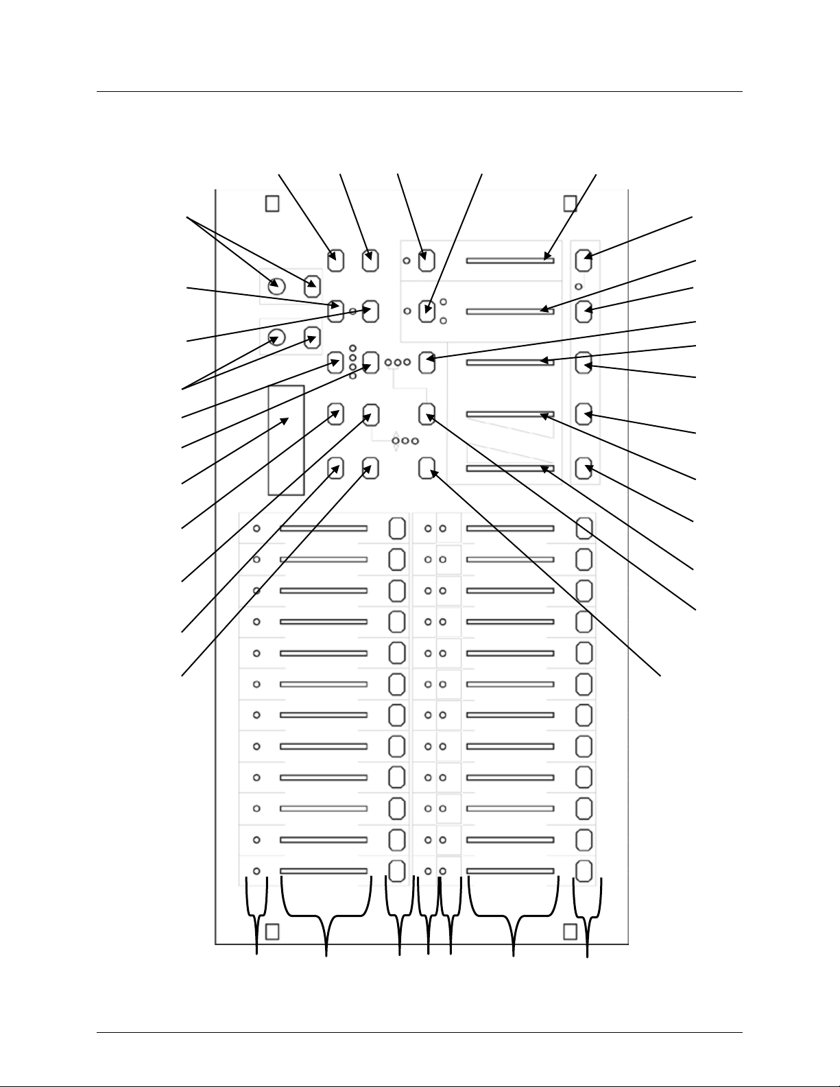
Product Overview
Front Panel View
2 1 3 6 5 8 9
11
14
16
17
18
15
12
31
32
7
24
10
19
13
30 1 2
29
28
27
25
26
22
23
20
21 4 4
Page 6 of 20 Stage Designer 50 User Manual Rev. 11
Page 7
Product Overview (cont.)
Front Panel
Item
Button/Fader/LED
Function
1
Channel Flash Buttons
Temporarily sets fader output to 100%
Controls channel output. 13/37–24/28 also control scene
playback
3
Scene Playback Indicators
LEDs indicate which scenes are playing back
4
Channel I n dicators
LEDs ind icate which ch ann els are outputtin g
5
Dark
Temporarily sets all outputs to 0%
Lowers selected value / Reverses chasing direction of all
scenes set to a tempo
7
Mode Select / Rec Speed
Cycles op erating modes / Programs a tempo for a scene
Raises selected value / Rev erses chasing direction of al l
scenes controlled by the speed fader
9
LCD Display
Displays the current state or mode
10
Page / Rec Clr
Cycles scene banks / Clears unsaved steps
Delet es a st ep in a sc en e / R ev er ses chasing direction of
selected scenes
12
Aux 1
Patchable, used to control a channel
Tempor ar il y bl in ds all but select ed ch annels / Exits from
Record and Edit modes
Adds a step or steps into a scene / T og gles percent and 0–
255
15
Aux 2
Patchable, used to control a channel
Activates Edit mode / Reverses chasing di rection of all
scenes
Activat es Record mod e, programs a step / Enables alternate
functions of buttons
18
Audio / Page A_B
Activat es au dio triggeri ng / Toggles channel page
19
Step
Continues to next step in Show and Edit modes
20
Audio Level Fader
Adjusts audio sensitivity
21
Blackout
Sets all output to 0% / R est ores normal output
22
Speed Fader
Sets scene playback tempo
23
Full On
Temporarily sets all outputs to 100%
24
Hold
Temporarily freezes playback to current state
25
Fade F a der
Sets fade times
26
Tap Sync
Sets playback speed when tapped repeatedly
27
Home
Deactiv ates blind on a sel ected channel
Controls total output of manual fader settings and Preset B
channels
29
Blind
Tempor ar il y d eac tivates a selec t ed ch annel output
30
Master Fader A
Controls t otal output of scenes and Preset A channels
31
Park
Togg les Single and Mix chase modes
32
No Function
Reserved for future use
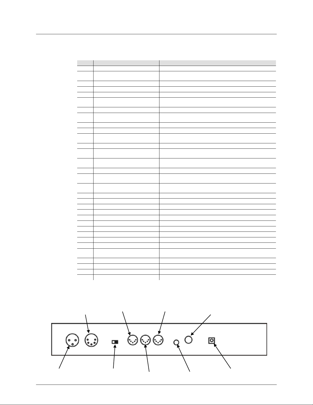
DC
Power In
Audio In
MIDI Thru
Polarity
Switch
MIDI Out
MIDI In
5-pin DMX
Out
Remote
Input
Channel Faders
2
Down / Beat Rev
6
Up / Chase Rev
8
Delete / Rev On e
11
Add Kill / R ec Ex i t
13
Insert / % or 0-255
14
Edit / All Rev
16
17
28
Record / Shift
Master Fader B
Back Panel View
3-pin DMX
Out
Stage Designer 50 User Manual Rev. 11 Page 7 of 20
Page 8

Common Terms
The following are common terms used in intelligent light programming:
Fixture: Any lighting or effect product, including but not limited to lights, fog machines, and
dimmers.
DMX: Stands for Digital Multiplexing, an i ndustry standard communica tion pr otocol used t o
control fixtures. For more information, download the DMX Primer from www.chauvetdj.com.
• Channel: A single DMX value, from 0 to 255, assigned to a single function or set of functions
for a f ixtu re.
audience.
a slider.
Step: A lighting state, in which the DMX signal is constant and unchanging.
Scene: A set of one or more steps arranged one after the other.
Chase: For this product, it is synonymous with Scene.
• MIDI: Stands for Musical Instrument Digital Interf ace, an industry standard method of digitally
representing musical information.
Speed: The amount of time for each step in a scene.
Beat: A pre-r ecorded speed.
out while the next fades in at the same time.
directly by the user at any time.
Page: Refers t o either Page A_B for channel select i on, or Page 1–4 for sc ene selec tion.
Product Dimensions
•
•
• Blackout: A state where the li ght output of al l fixtures is set to 0/off. Usually temporary . For
example: in theater, this allows stage sets to be changed or moved wi t hout being seen by the
• Fader: A component that moves smoothly up and down to set a desired value. Also known as
•
•
•
•
•
• Fade: The amount of time it takes to switch between steps in a scene, in which one st ep fades
• Playback: Programmable memory of steps or scenes that can be executed during a show or
10.5 in
267 mm
•
19 in
483 mm
Page 8 of 20 Stage Designer 50 User Manual Rev. 11
Page 9

DC Power
rangi ng power supply and it can wor k wi th an
’s average current draw under normal
completely dis connect the product f rom pow er via breaker or by unplugging it.
to a rh eostat (varia ble resist or) or dimm er circuit, even if th e
Setup
the other
as described in
If you ar e not fam i li ar wit h t he D MX pr oto col, downloa d t h e
Page Selection
3. OPERATING INSTRUCTIONS
The Stage Designer 50 has an external, autoinput voltage range of 100 to 240 VAC, 50/60 Hz. To determine the product’s power
requirements (ci rcui t break er, pow er out l et, an d wiri ng) , us e the cur r ent val ue li st ed on the
label af f ixed to the power su ppl y’s back panel, or refer to the product’s specifications chart.
The listed current rating indicates the product
conditions.
• Always connect the product to a protected circuit (ci rcuit breaker or fuse). Make
sure the product h as an appropriate electrical ground to avoid the risk of
electrocution or fire.
• To eliminate unnecessary wear and improve it s lifespan, during periods of non-use
Never c onnect the product
rheostat or dimmer channel serves only as a 0 to 100% switch.
1. Place th e Sta ge Designer 50 on a level surfa ce, or rack-mount it. When rack-mounted,
it occupies six rack spaces (6U).
2. Plug one end of the ext er nal power suppl y into the product’s back panel and
end into a grounded/protected pow er out let.
3. Plug i n your DMX ca ble( s) to the l ight ing f ixt ures you wi sh t o c ontrol
their r esp ecti v e man uals.
DMX Primer from www.chauvetdj.com.
4. For first time use only: Reset the Stage Designer 50 system. (See Master Reset)
Black Out m ust b e turned off at star t-up, or t her e will b e no DMX out put. T o toggl e Black
Out, press the <BLACKOUT> button. The in di c ator LED will be on if Black Out is on, or off
if Black Out is off.
The Stage Designer 50 has 24 faders, but 48 channels of DMX output. This works
because the channel outputs are split between two Pages: Page A and Page B. Page A
sets the faders as channels 1–24. Page B sets the faders as channels 25–48. At startup,
the prod uct will be set to the page that was set when it was powered do wn. The LCD
display will show which page is currently set.
To toggl e between Page A and Page B:
1. Press and hold the <RECORD / SHIFT> button.
2. Press the <AUDIO / PAGE A_B> button.
3. Release <RECORD / SHIFT>.
Channel pages A and B are unrelated to the pages in the Scene Bank (1–4).
Stage Designer 50 User Manual Rev. 11 Page 9 of 20
Page 10

Master Faders
. Their functions depend on what mode the
Crossfade Mode
faders, w hile
24. This mode allow s the
user to fade smoothly between two preset looks at will, as well as control the channels
Chase◄►Scene
controls the total out put of the currently
, on the other hand, controls the output of the physical
to its maximum position (fully up) for maximum effect.
positions are higher
will contr ol
Channel Mode
Mode
There are two MASTER faders: A and B
product is set to.
To toggle through the modes, tap the <MODE SELECT / REC SPEED> button repeatedly.
In Crossfade mode, MASTER fader A contro ls the output of t he PRESET A
MASTER fader B controls the output of the PRESET B fader s . In t his mode, PRESET A
and PRESET B will control the same 12 channels at all times . On Page A, the y will control
channels 1 – 12, and on Page B they will control channels 13 –
live witho ut the need to pr ogram a scene or scenes.
To operate t he Stage D esign er 50 in Cross fade mode :
1. Start with both MASTER faders all the way down.
2. Press the <MODE SELECT / REC SPEED> button repeatedly until the yellow
indicator LED for 1-12A / 1-12B is lit.
3. Compose the first look with the faders in PRESET A (1 / 25 – 12 / 36).
4. Slide bo th MASTER faders up simultaneously. PRESET A will be active.
5. Compose the next l ook with the faders in PRESET B (13 / 37 – 24 / 48).
6. To switch to PRESET B, slide both MASTER faders all the way down simu ltaneously.
7. Repeat steps 3 – 6 a s desired.
In Chase◄►Scene mode, MASTER fader B
sel ect ed s c ene. MASTER fader A
faders 1 / 25 – 12 / 36.
To set the product to Chase◄►Scene mode, press the <MODE SELECT / REC SPEED>
button until the red indicator LED for Chase◄►Scene lights up.
To utilize MASTER fader B in Chase◄►Scen e mode:
1. Move the MASTER fader B to its maximum position (fully down) for maximum effect.
Adjust it for desired Record Mode and Scene Playback out put. See Play i ng a Scene
for instructions on playing back recorded scenes.
To utilize MASTER fader A in Chase◄►Scen e mode:
1. Mov e the MASTER fader A
Adjust it for desired manual output.
2. Move faders 1 / 25 – 12 / 36 t o desired override positions.
NOTE: Fad er s wil l o nly o verr i de th e reco rd ed s cen e whi le new
than recorded positions.
In Channel mode, MASTER fader B has no function. Only MASTER fader A
the output of all channels.
To set the product to Channel mode, pres s t he <MO DE SELECT / REC SPEED> button
until the green indicator LED for 1-24 A lights up.
Page 10 of 20 Stage Designer 50 User Manual Rev. 11
Page 11

Enable R ec or d
mo de m us t b e
Create a Scene
recor d programs for pl ayback, known as
Compos e the fi rst st ep ( Step 0 00) fo r the sc ene by m ovin g the f aders t o th e desir ed
Repeat steps 3 and 4 until the desired number of steps have been programmed, up to
) to
Playing a
MASTER
Record Clear
Whil e recordi ng a s cene, i f you wis h to star t ov er and erase all unsav ed st eps, foll ow th e
All Chan nel LE Ds wi ll flash, indi c ati ng th e st eps
Record
4. RECORD MODE
For al l pro gramming f unctio ns in t he Stag e Design er 50 sy stem, Record
enabled.
To enable Record:
1. Press and hold the <RECORD / SHIFT> button.
2. While holding <RECORD / SHIFT>, tap the flash buttons in the following sequence:
<1 / 25>, <5 / 29>, <6 / 30>, <8 / 32>. (1, 5, 6, 8.)
3. Release <RECORD / SHIFT>. The Record LED will light up.
To exit Record:
1. Press and hold <RECORD / SHIFT>.
2. Tap the <ADD KILL / REC EXIT> button. All Channel LEDs will flash.
3. Release <RECORD / SHIFT>.
The Stage Designer 50 allows the user to prescenes or chases.
To create a scene:
1. Enable Record.
2. Press the <MODE SELE CT / REC SPEED> button until the green indicator LED for 1-
24 A lights up.
3.
positions.
4. Press the <RECORD / SHIFT> button to save the step to temporary memory.
5.
Step 999 for one scene. After pressing <RECORD / SHIFT>, the display will read Step
_ _ _ (the current scene number).
6. Select the page (Scene Master) in which to save the scene, by pressing the
<PAGE / REC CLR> button until the LED indicates the desired page.
7. Press an d hol d <RECORD / SHIFT>, and ta p a fl ash butt on (<13 / 37>–<24 / 48>
save the scene to t ha t f ader for play back.
8. Continue programming, or exit Record.
Once a scene is recorded and saved, it can be recalled and played back using the fader to
Scene
Stage Designer 50 User Manual Rev. 11 Page 11 of 20
which it was assigned. To select a scene for playback, follow the instructions below:
1. Press the <MODE SELECT / REC SPEED> button until the red i ndicator L ED for
Chase◄►Scene light s up.
2. If necessary, use the <PAGE / REC CLR> button to select the page to which the desired
scene is saved.
3. Push the MASTER fader B to its maximum position (fully down).
4. Set t he SPEED and FADE fad ers to t h e d esir ed posi ti ons. ( See Speed and Fade
more information.)
5. Bring the fader for the scene you wish to play back up to the desired output level. Adjust
the output level of the scene by moving the scene’s fader.
6. Adjust the total output of all scenes with the
instruc t ions below:
1. Do NOT save the scene.
2. Press and hold the <RECORD / SHIFT> button.
3. Tap the <PAGE / REC CLR> button.
have been cleared.
4. Release <RECORD / SHIFT>.
5. Continue programming, or exit
for
fader B.
.
Page 12

Enable Edit
to select th e pa ge to whic h th e d esired s c ene i s
<RECORD / SHIFT>
Record
Delete a Scene
<DELETE / REV ONE>
Delete a Step
or Steps
Insert a Step or
Steps
to cycl e thro ugh th e steps of the s cene. S elect th e st ep you
Edit
Modify a Step
or Steps
to cy cle throu gh the st eps of th e scene unti l the st ep to be
5. EDIT MODE
In order to make any changes to the steps in a scene or scenes, Edit must be enabled.
To enable Edit:
1. Enable Record.
2. Press the <MODE SELECT / REC SPEED> button unti l the red i ndicator L ED for
Chase◄►Scene lights up.
3. Use the <PAGE / REC CLR> button
saved.
4. Press and hold the <EDIT / ALL REV> button, and tap the flash button (<13 / 37>–<24
/ 48>) of the desired scene.
5. Release <EDIT / ALL REV>. The s elected scene LED will light up, indicating the
product is in Edit mode.
To exit Edit:
1. Press and hold the <RECORD / SHIFT> button.
2. Tap the <ADD KILL / REC EXIT> button. All Channel LEDs will flash.
3. Release
To delete a single entire scene, do the following:
1. Enable Edit for the scene to be deleted.
2. Press the
. The controller will be back in
button three times.
mode.
To delete one or multiple steps within a saved scene:
1. Enable Edit for the scene to be edited.
2. Use the <STEP> button to cycle through the steps of the scene until the desired step is
selected.
3. Press the <DELETE / REV ONE> button once to delete the selected step.
4. Repeat steps 2 and 3 until all unwanted steps have been d el eted.
5. Conti nue editing, or exit Edit.
To insert a steps or steps into a previously saved scene:
1. Enable Record and record the step or steps you wish to be inserted.
2. Enable Edit for the scene into which you wish to insert the new step or steps.
3. Use the <STEP> button
wish to be after the inserted step or steps.
4. Press the <INSERT / % or 0 -255> button t o ins ert th e n ew step or st eps before the
selected step. All Channel LEDs will flash.
5. Conti nue editing, or exi t
To modify an existing step within a previously saved scene.
1. Enable Edit for the scene to be edited.
2. Use the <STEP> button
edited is selected.
3. Press and hold either:
• The <DOWN / BEAT REV> button if you wish to lower a value.
or
• The <UP / CHASE REV > button if you wish to raise a value.
4. Tap or hold the <FLASH> button of t he channel y ou wish to edi t . Tapping will chan ge
the value by 1 at a time. Holding will cause the value to rise or fall smoothly.
5. Repeat steps 2, 3, and 4 until all desired modifications have been made.
6. Conti nue editing, or exi t Edit.
Moving the channel faders in Edit mode has no effect on the recorded scene. The
changes will not be saved.
.
Page 12 of 20 Stage Designer 50 User Manual Rev. 11
Page 13

Audio
Speed
Unless a beat has b een recorded, a scene’s play back speed wil l depend on th e posi tion of
with th e currently
The fastest speed is 20 mi ll is econds. The
Show Mode
. The display will
and tap t he f las h but t on
All cha nnel an d scen e LEDs wi ll fl ash, i ndic ating t h e beat
beat has b een
again. The display will read the time in
TAP SYNC
SPEED
6. PLAYBACK OPTIONS
The Stage Designer 50 is capabl e of responding to sound. I t can us e either its own built-in
Triggering
microphone or an alternative audio source, through the audio line in jack on the back panel.
To enable audio triggering:
1. Play back a scene.
2. Press the <AUDIO / PAGE A_B> button. The indicator LED above it will light.
3. Use the AUDIO LEVEL fader to adjust the sensitivity.
The steps of the scene playing will now be triggered by sound.
To disable audio triggering, press <AUDIO / PAGE A_B> again. The indicator LED above it
will turn off.
the SPEED fader. Adjusting it up or down will affect the amount of time before the next step
is trig g ered. Wh en it i s m ov ed, t he di spla y wil l r ead SPEED _ _m_ _ s_ _
set ti m e in m i nut es, s eco nds, an d m il lis econ ds.
slowest speed is 5 minutes or 10 minutes, depending on the speed mode.
Speed co nt r ols will not work if Audio Triggering is enabled.
The SPEED fader also has a setting for manual triggering, called show mode. Unless a beat
has been recorded, show mode can be enabled by doing the following:
1. Play back a scene.
2. Mo v e the SPEED fad er to it s lo west po sit ion, l a bell ed S HO W M ODE
read SPEED 29m07s12.
3. Tap the <STEP> button to trigger the next step, exactly when you desire.
Show mode will only work with the SPEED fader at its lowest position. Any higher, and the
<STEP> button will not have any ef fect.
Beat Mode
Scen es can be s et to run at a user s et speed or beat. T his ca n be don e with th e SPEED
fader or t he TAP SYNC feature.
To record a beat with the speed fader, follow the instructions below:
1. Play back the scene you wish to set to a beat.
2. Press the <PARK> button until the LED (yellow) indicating Mix Chase is lit.
3. Move t he SPEED fader to the desired position.
4. Press an d h old the <MOD E S ELEC T / REC SPEED> button
To disable a beat recorded this way, and return control to the SPEED fader:
1. Play back the scene with the beat you wish to disable.
2. Press <PARK> until the LED (yellow) indicating M ix Chase is lit.
3. Move t he SPEED fader to its lowes t po s ition ( SHOW MODE).
4. Press and hold < MODE SE LECT / REC SPEED > and tap the flash button of the scene
To record a beat with the TAP SYNC feature:
1. Play back the scene you wish to set to a beat.
2. Press the <T AP SYNC> button.
3. Wait t he desired ti me and press < T AP SY N C>
4. Repeat step 3 if necessary to get the timing right.
To disable a beat recorded with
of t h e sc en e playing bac k.
has been recorded.
playing back. All channel and scene LEDs will flash, indicating the
disabled.
between presses, and the steps will be triggered at that speed.
, move the
fader.
Stage Designer 50 User Manual Rev. 11 Page 13 of 20
Page 14

Speed Modes
Fade
in and out. The
The maximum FADE value is 10 minutes. The minimum is ins tant.
Single Chase
Mix Chase
The SPEED fader has two modes, 5 min and 10 min.
To set it to 5 min mode:
1. Press and hold the <RECORD / SHIFT> button.
2. Press the <5 / 29> flash button three times.
3. Release <RECORD / SHIFT>. The LED indicator for 5 min mode will be lit.
To set it to 10 min mode:
1. Press and hold <RECORD / SHIFT>.
2. Press the <10 / 34> flash button three times.
3. Release <RECORD / SHIFT>. The LED indicator for 10 min mode will be lit.
The FADE fader sets the period of time each recorded step takes to fade
higher the value it is set to, the lon ger the dimmer curve for the system.
• FADE val ue can not be recorded.
•
In Single Chase mode, the Stage Designer 50 will cycle through all activated scenes, at
Mode
the speed set by the SPEED fader, TAP SYNC, or Audio Triggering.
To o perate in Single Chase mode:
1. Press the <PARK> button until the LED (red) indicating Single Chase is lit.
2. Bring the fader or faders for the scene(s) you wish to cycle to the desired output
level(s). The St age Designer 50 will cycl e through them in order .
Recorded beat s/ speeds will not work i n this mode.
One of the features of the Stage Designer 50 is the ability to layer scenes. This allows
Mode
two or more scenes to outp ut simultaneously .
To layer scenes together, do the following:
1. Press t he <PARK> button unti l the LED ( yell ow) indicati ng Mix Chase is lit.
2. Bring the fader or faders for the scene(s) you wish to play back simultaneously up to
the desired out put level(s) .
3. Adjust the output of each scene as necessary.
• Manual cross-fadin g of scenes will o nly work properly in this mode .
• Recorded beats/ speeds will only work in this mode.
Page 14 of 20 Stage Designer 50 User Manual Rev. 11
Page 15

Black Out
Black Out
Black Out
Dark
Hold
While a scene is playing back, press and hold the <HOLD> button to freeze DMX output to
<HOLD>
Blind and
Pressing the <BLIND> button and a channel’s flash button at the same time will black out
Reverse
NOTE
% or 255
Add Kill
Full On
<FULL ON> is released, the output will jump to the step currently being processed.
Master Reset
To reset the product to factory settings, deleting all scenes, settings, and data, do the
4. Release <RECORD / SHIFT>. All channel LEDs will flash .
7. OTHER FUNCTIONS
Black Out stops all DMX output from the controller. Func tion s will s till wo rk du ring Black
Out, but there will be no DMX output. To toggle Black Out:
Press the <BLACKOUT> button.
The yellow indicato r LED for
At any time, pressing the <DARK> button will te mpo rarily black out the controller.
Releasing <DARK> w ill restore DMX output. Scenes playing back will continue while
DARK.
its current state. Rel ease <HOLD> to unfreeze. Although DMX output will freeze, the
scene will continue.
Releasing
will be lit if
is activ e.
will cause the output to jump to the step currently being processed.
Home
Functions
that channel.
Pressing the <HOME> button and a blinded channel’s flash button at the same time will
restore its function.
There are four reverse functions available to the Stage Designer 50:
1. Beat Reverse: pressing the <DOWN / BEAT REV> button will reverse the pla yback
of all scen es that have a b eat recorded. This is effective even in Single Chase
mode.
2. Chase Reverse: pressing the <UP / CHASE REV> button will reverse the playback
of all scenes t hat do not have a beat recorded.
3. Reverse One: pressing the <DELETE / REV ON E> button will revers e the playback
of selected scenes.
4. All Reverse: pres sing the <EDIT / ALL REV> button will reverse the playback of all
scenes.
: Reverse functions remain the same with Audio Triggering activated.
The Stage Designer 50 can display fader and auxiliary states as DMX values or as a
percentage out of 100. To toggle the number system:
1. Press and hold the <RECORD / SHIFT> button.
2. Press the <INSERT / % or 255> button.
3. Release <RECORD / SHIFT>. The number system will have changed.
Pressing the <ADD KILL / REC EXIT> button during playback will toggle Add Kill mode,
which will be shown by the indicator LED being lit.
In Add Kil l mode, pressing a flash button <1 / 25>–<12 / 36> will bring that channel to full
output and black out all other channels. The scene will continue to play back in the
background, but only the selected channel will output.
Releasing the flash button will cause the output to jump to the step currently being
processed.
Pressing the <FULL ON> button will cause all 48 DMX channels to output 100%.
Releasing <FULL ON> will restore normal function. If a scene is playing back when
following:
1. Enable Record.
2. Press and hold the <RECORD / SHIFT> button.
3. While holding <RECORD / SHIFT>, tap the flash buttons in the following sequence:
<1 / 25>, <3 / 27>, <2 / 26>, <3 / 27>. (1, 3, 2, 3.).
Stage Designer 50 User Manual Rev. 11 Page 15 of 20
Page 16

Auxiliary
NOTE: Record mode does not have to be enabled to assign or disable auxiliaries.
There are t wo Aux knobs, both with a flash button. They can be assigned to act as
Controls
shortcuts for DMX channels. There are 3 auxiliary modes, called functi ons:
1. FUNC 01: Disables the auxiliary knob and flash button.
2. FUNC 02: The auxiliary knob and flash button functions exactl y as the original fader
and flash button did.
3. FUNC 03: The auxiliary knob sets the output value of the auxiliary flash button.
(Example: Set the knob to 255, and the channel will output 255 when the flash
button is pressed.)
To assign a channel and function to an Aux knob and flash button, follow the
instructions below:
1. Press and hold the <REC ORD / SHIFT> button.
2. For:
• Aux 1: Press the <7 / 31> f lash b utton t hree ti mes.
• Aux 2: Press the <8 / 32> f lash b utton t hree ti mes.
3. Release <RECORD / SHIFT>. The display will show the current status of the Aux
being set.
4. Press and hold <RECORD / SHIFT> again.
5. Press one of the following flash buttons:
• <1 / 25> for FUNC 01.
• <2 / 26> for FUNC 02.
• <3 / 27> for FUNC 03.
6. Release <RECORD / SHIFT>.
7. Press t he <FLASH> button of t he channel you wish to assign to the auxiliary.
8. Press and hold <RECORD / SHIFT>.
9. Tap the <ADD KILL / REC EXIT> button.
10. Release <RECORD / SHIFT>.
• If an auxil iary is set to FUNC 02, the original fader and flash button for the assigned
channel will not function.
• If an auxil iary is set to FUNC 03, the original fader and flash button will still function,
but the highest value between them and the auxiliary will take precedent.
(Example: If th e fader i s set to 200, and t he Aux knob is set to 255, the <Aux> flash
button will override the fader. If the Aux knob is set lower than the fader, the <Aux>
flash button will have no effect.
Page 16 of 20 Stage Designer 50 User Manual Rev. 11
Page 17
MIDI Operation
The Stage Designer 50 can also respond to an external MIDI controller, using “note-on”
commands. All other MIDI commands are ignore d.
Setting MIDI
To assign the co ntroller a MIDI chan nel to receive and send MIDI commands, do the
MIDI THRU.
MIDI Control
22–69
Trigger scenes 1–48 (100%)
70–117
Activate Channel 1–48
118
Full-On
119
Dark
120
Hold
121
Togg le Audio
122
Ch ase◄ ►S cen e m ode
123
1-12A_1-12B mode
124
1-24A mod e
Step
126
BLACKOUT
127
Toggle Page A/B (1–24/25–48)
MIDI can be u sed to c opy the s aved memory co ntents (also called the sh ow) from one
<RECORD / SHIFT>.
In/Out
Chart
following:
1. Press and hold the <RECORD / SHIFT> button.
2. For:
• In: Press the <1 / 25> flash button three times.
• Out: Press the <2 / 26> fl ash button thr ee tim es.
3. Release <RECORD / SHIFT>.
4. Select the MIDI channel (1–16) by pressing the corr esponding flash button
(<1 / 25>–<16 / 40>).
5. Press and hold <RECORD / SHIFT> and press the <ADD KILL / REC EXIT>
button.
6. Release <RECORD / SHIFT>.
NOTE: The controller will only respond to commands on the assigned MI DI channel,
and only output on the assigned MIDI channel. To output all MIDI input , connect to
MIDI Note FUNCTION (TURN ON/OFF)
125
MIDI File Dump
Stage Designer 50 to another Stage Designer 50. The process i s called MIDI File
Dump, and wi ll not work with any other device.
To p erform a MIDI File Dump, first prepare the c ontroller to receive the pr ogrammed
show. Follow the instructions below, on the controller you wi sh to receive the fil e dump:
1. Press and hold the <RECORD / SHIFT> button.
2. Press the <3 / 27> flash button th ree times.
3. Release <RECORD / SHIFT>.
The display will read MIDI FILEDUMP RECVING 000 %.
Next, connect the MID I IN jack on t he receiving controller t o t he MIDI OUT jack on the
sending controller. Then set up the sending controller to send the fil e dump. On the
controller you wish to send the file dump, do the following:
1. Press and hold <RECORD / SHIFT>
2. Press the <4 / 28> flash button th ree times.
3. Release <RECORD / SHIFT>.
The display will read MIDI FILEDUMP SENDING 000%.
The file dump wil l begin im mediately, and the n umbers on both displa ys will show the
progres s. The pr ocess c an take s everal minutes to complete. During the file dump, all
other operations will cease to function.
When the file dump is completed, press and hold <RECORD / SHIFT> and press
<ADD KILL / REC EXIT> on both controllers to exit MID I mode. Then release
If a n error or power failure occurs, th e f ile dump will be interrupted and stop.
Stage Designer 50 User Manual Rev. 11 Page 17 of 20
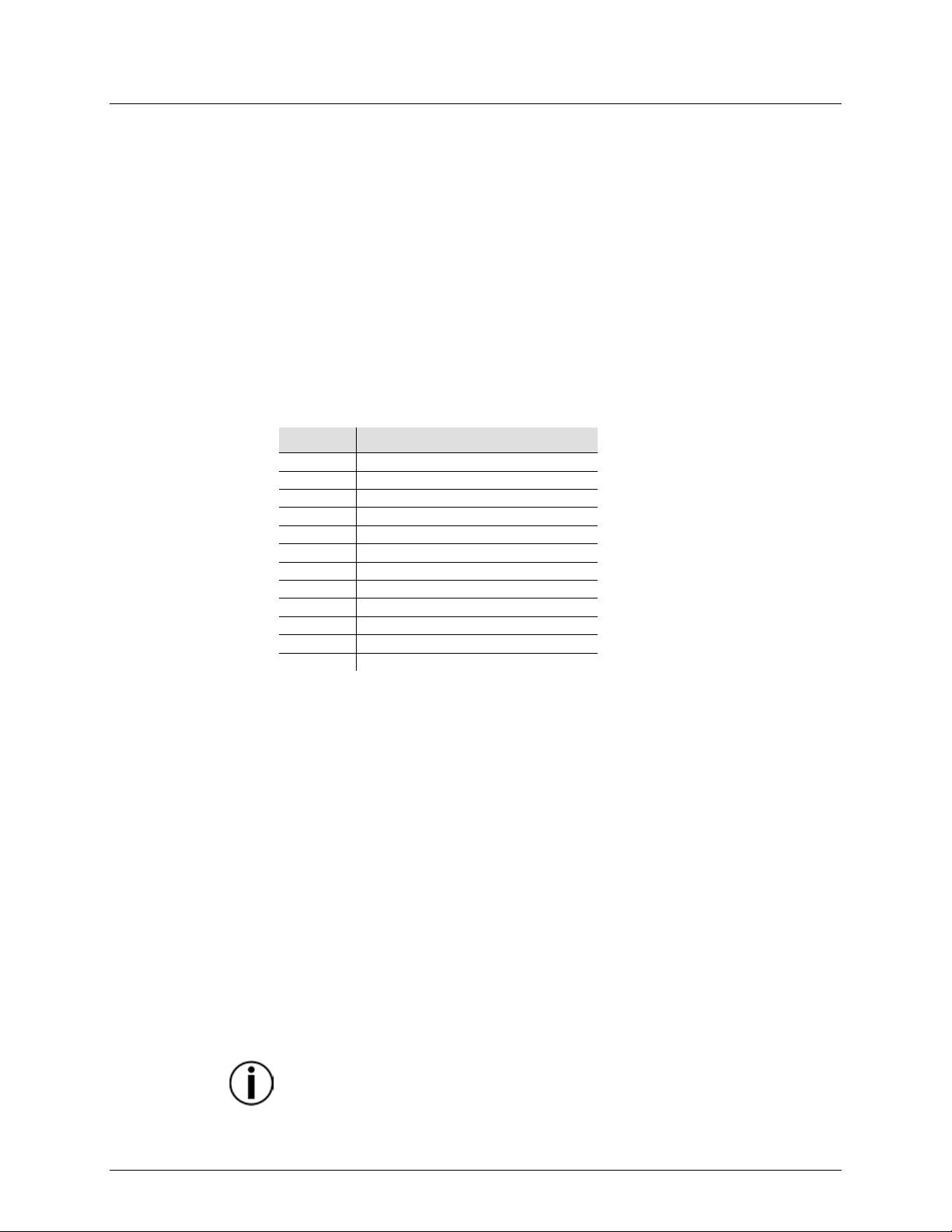
Page 18
Dimensions and
Length
Width
Height
Weight
19 in (483 mm)
10.5 in (267 m m)
3.5 in (89 mm)
9.9 lb (4.5 kg)
Note: Dimensions in inches rounded to the nearest decimal digit.
Rackmount
6U
Power
Value
Stage Designer 50
External Power Supply
Input Voltage
Fixed
Switching
Range
12 VDC, 500 mA
100 to 240 VAC, 5 0/60 Hz
Voltage Selection
Fixed
Auto-ranging
Thermal
Maximum External Temp.
Cooling Syste m
104 °F (40 °C)
Convection
DMX
Output Connectors
Channels
3 and 5-pi n X LR
48
Ordering
Product Nam e
Item Code
UPC Number
Stage Designer 50
09080283
781462202637
8. TECHNICAL SPECIFICATIONS
Weight
Page 18 of 20 Stage Designer 50 User Manual Rev. 11
Page 19

R
In case you need to get support or return a product:
If you are located outsi de the U.S., UK, Ireland, Benelux, France, Germany, or
con tact d etails.
Call the corresponding Chauvet Technical Support office and request a Return
returned without an RMA number.
Before sending the product, clearly write the following information on a piece of paper
recommended.
ETURNS
• If yo u are located in the U. S., contact Chauvet World Headquarters.
• If you are l ocated in the UK or Ireland, contact Chauvet Europe Ltd.
• If you ar e located in Benelux, cont act Chauvet Eu rope BVB A .
• If you are located i n Franc e, contact Chauvet France.
• If you are located in Germany, contact Chauvet Ger many.
• If you are l ocated in Mexico, contact Chauvet Mexico.
• If you are l ocated in any other country, DO NOT contact Chauvet. Instead, contact
you r local distributo r . See www.chauvetdj.com
Ireland, Benelux, France, Germany, or Mexico.
Mexico, contact your dist ributor of record and follow their instructions on how to
return Chauvet products to them. Visit our website
Merchandise Authorization (RMA) number before shipping the product. Be prepared to
provide the model number, serial number, and a brief description of the cause for the
return.
To s ubmit a s ervic e request online, go t o www.chauvetdj.com/service-request.
Send the merchandise prepaid, in its original box, and with its origi nal packing and
accessories. Chauvet wil l not issue cal l tags.
Clearly label the package with the RMA number. Chauvet will refuse any product
Write the RMA number on a properly affixed label. DO NOT writ e the RMA number
directly on the box.
for distributors outside the U.S., UK,
www.chauvetdj.com for
and place it inside the box:
• Your name
• Your address
• Your phone number
• RMA n umber
• A brief description of the problem
Be sure to pack the product properly. Any shipping damage resulting from inadequate
packaging will be your responsibility. FedEx packing or double-boxing are
Chauvet reserves the right to use its own discretion to repair or replace returned
product(s).
Stage Designer 50 User Manual Rev. 11 Page 19 of 20
Page 20

C
General Information
Technical Support
Chauvet World Headquarters
Address: 5200 NW 108th Avenue
Toll free: (800) 762-1084
Voice: (844) 393-7575
Website www.chauvetdj.com
Chauvet Europe Ltd
Address: Unit 1C
Email: UKtech@chauvetlighting.eu
Chauvet Europe BVBA
Address: Stokstr aat 18
Email: BNLtech@chauvetlighting.eu
Chauvet France
Address: 3, Rue Ampère
Voice: +33 1 78 85 33 59
Email: FRtech@chauvetlighting.fr
Chauvet Germany
Address: Bruno-Bürgel-Str. 11
Voice: +49 421 62 60 20
Email: DEtech@chauvetlighting.de
Chauvet Mexico
Address: Av. de las Parti das 34-3B
Voice: +52 (728) 690-2010
Email: servicio@chauvet.com.mx
Outside the U.S., U.K., Ireland, Benelux, France, Germany, or Mexico, contact the
our website for contact details
ONTACT
US
Sunrise, FL 33351
Voice: (954) 577-4455
Fax: (954) 929-5560
Brookhill Road Industr ial Estate
Pinxton, Nottingham, UK
NG16 6NT
Voice: +44 (0)1773 511115
Fax: +44 (0)1773 511110
9770 Kruishoutem
Belgium
Voice: +32 9 388 93 97
91380 Chilly-Mazarin
France
Fax: (954) 756-8015
Email: chauvetcs@chauvetlighting.com
Website: www.chauvetdj.eu
Website: www.chauvetdj.eu
Website: www.chauvetdj.eu
28759 Bremen
Germany
(Entrance by Call e 2)
Zona Industri al Lerma
Lerma, Mexico C.P. 52000
Page 20 of 20 Stage Designer 50 User Manual Rev. 11
dealer of recor d. Foll ow the instructions to request support or t o retur n a product . Visit
Website: www.chauvetdj.eu
Website: www.chauvetdj.mx
 Loading...