

Page 1

User Manual
Page 2

TABLE OF CONTENTS
1. Before You Begin ...........................................................................................................3
What Is Included ......................................................................................................................... 3
Unpacking Instruc tions ................................................................................................................ 3
Claims ................................................................................................................................................. 3
Text Conventions ........................................................................................................................ 3
Symbols ...................................................................................................................................... 3
Disclaimer ................................................................................................................................... 3
Product at a Glance ..................................................................................................................... 4
Safety Notes ............................................................................................................................... 4
2. Introduction ....................................................................................................................5
Overview ..................................................................................................................................... 5
Dimensions ................................................................................................................................. 6
3. Setup ...............................................................................................................................7
AC Power .................................................................................................................................... 7
Fus e Repl acement ............................................................................................................................... 7
Power Linking ...................................................................................................................................... 8
Mounting ..................................................................................................................................... 9
Orientation ........................................................................................................................................... 9
Rigging ................................................................................................................................................ 9
4. Operation ......................................................................................................................10
Control Panel Operation ............................................................................................................ 10
Menu Map ................................................................................................................................. 10
Configuration ( DM X) .................................................................................................................. 11
Starting Address ................................................................................................................................ 11
DMX Channel Modes, Assignments, and Values ....................................................................... 11
8-Channel .......................................................................................................................................... 11
4-Channel .......................................................................................................................................... 11
Configuration ( S tandalone) ........................................................................................................ 12
Sound-Active Mode ............................................................................................................................ 12
Automatic Mode ................................................................................................................................. 12
Static Mode........................................................................................................................................ 12
Cus tom Stati c Col ors.......................................................................................................................... 12
Master/Slave Mode ............................................................................................................................ 13
Infrared Remote Control ..................................................................................................................... 13
IRC (Infrared Remot e Control) Operation ............................................................................................ 14
5. Technical Information ..................................................................................................15
Product Maintenanc e ................................................................................................................ 15
6. Technical Specifications ..............................................................................................16
Returns ..................................................................................................................................... 17
Contact Us ................................................................................................................................ 17
Page 2 of 17 SlimPAR™ QUAD 6 IRC User Manual Rev. 2
Page 3
What Is
Unpacking
Instructions
and check the container t o make sure all the
included accessories) appear damaged from
, damage not relat ed to shipping,
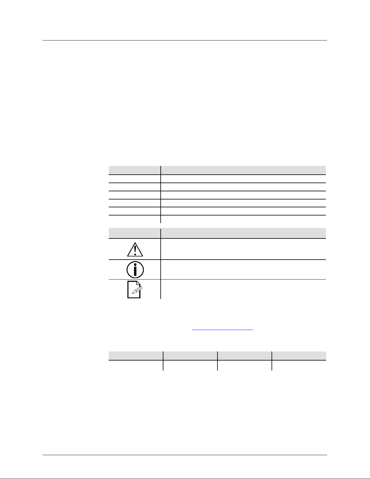
Text
Convention
Meaning
1–512
A range of values
50/60
A set of values of which only one can be chosen
Settings
A menu option not to be modified
Menu > Settings
A seq uence of menu opti ons to b e followed
<ENTER>
A key t o be pr essed on th e product’s control panel
ON
A value t o be entered or selected
Symbols
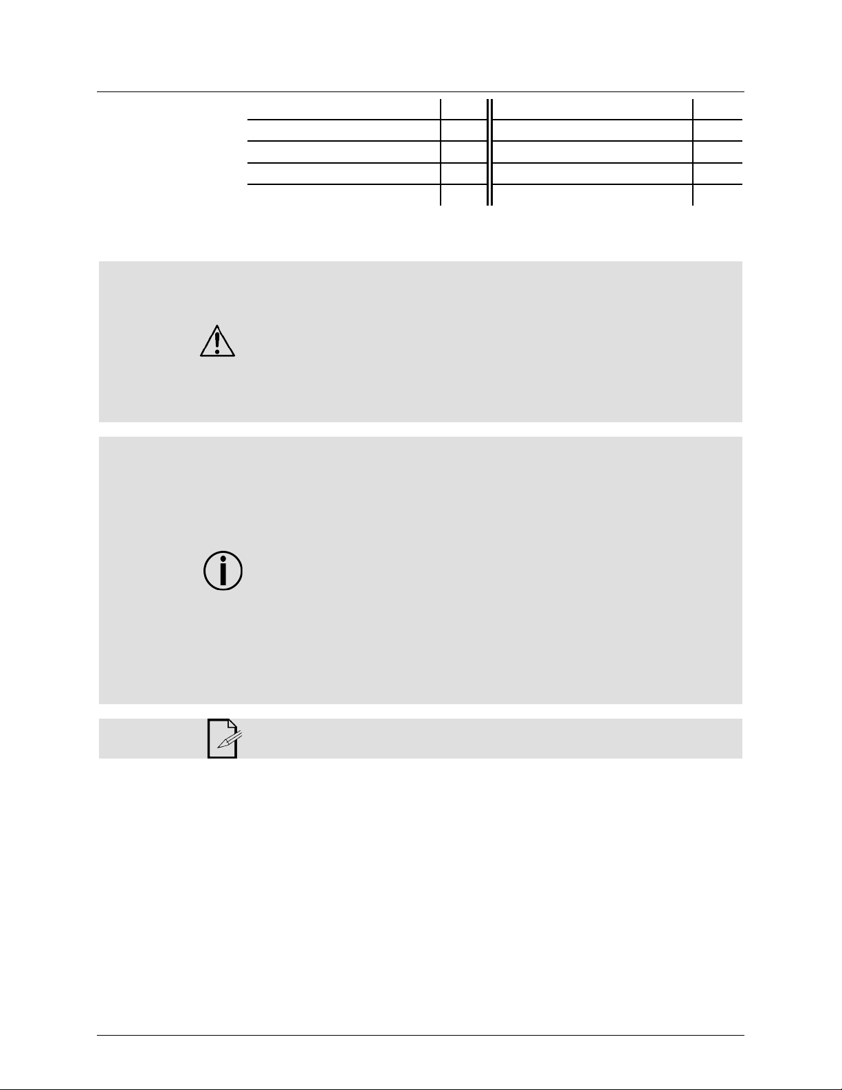
Critical installation, configuration, or operation informa tion. Not
damage to the product, or cause harm to the operator.
Disclaimer
are subject to change
ity for any errors or
1. BEFORE YOU BEGIN
Included
Claims
Conventions
• SlimPAR™ QUAD 6 IRC
• Power Cord
• Gel Frame
Carefully unpack the product immediately
parts are in the package and ar e in good condition.
If the box or the contents (the product and
shipping, or show signs of mishandling, notify the carrier immediately, not CHAUVET®.
Failure to report damage to the carrier immediately may invalidate your claim. In
addition, keep the box and contents for inspection.
For ot her iss ues, such as missing components or parts
or concealed damage, file a claim with CHAUVET® within 7 days of delivery.
Symbol Meaning
• Warranty Card
• Quick Reference G uide
The information and specifications contained in this User Manual
without notice. CHAUVET® assumes no responsibility or liabil
omissions, and reserves the right to revise or recreate this manual at any time.
Download the latest version from
© Copyright 2013 CHAUVET®. All rights reserved.
Electronically published by CHAUVET® in the U nited St ates of Am er ica.
Author Date Editor Date
A. Leon 6/5/13 T. Yeago 06/05/13
following these instructions may make the product not work, cause
Important installation or configuration information. The product
may not function correctly if this i nformation i s not us ed.
Useful information.
www.chauvetlighting.com.
SlimPAR™ QUAD 6 IRC User Manual Rev. 2 Page 3 of 17
Page 4
Product at a
x
P
x
P
P
P
P
x
P
x
Safety Notes
• Always make sure that the voltage of the outlet to which you are connecting the
Glance
Use on Dimmer
Out door Use
Sound-Activated
DMX
Master/Slave
These notes include important information about the mounting, usage, and maintenance
of this product; read before using the product.
• Always connect the product to a grounded circ uit to avoid the risk of electrocution.
• Always disconnect the product from the power source before cleaning or replacing
the fuse.
• Avo id di rect eye exp osure to the l ight sour ce whi le th e product is on.
• Make sure the power cord is not crimped or damaged.
• Never disconnect the product from power by p ul li ng or tugging on the c ord.
• If mounting the product overhead, always secure to a fastening d evice using a
safety cable.
• Make sure th ere are no flammable materials close t o the product when operating.
• Do not touch the product’s housing when operating because it may be very hot.
product is within the range stated on the decal or rear panel of the product.
• The product is for indoor us e only! (I P20) T o prevent risk of fire or shock, do n ot
expose the product to rain or moistu re.
• Always install the product in a location with adequate ventilation, at least 20 i n
(50 cm) from adjacent surfaces .
• Be su re that no ventilation slots on the product’s housing are blocked.
• Nev er co nnect the product to a dimmer.
• Make sure to repl ace the fus e w ith a noth er of t he same typ e and r ati ng.
• Nev er ca r ry the product fr om the power cord or an y moving pa rt. Alwa ys use the
hanging/mounting bracket or the handles.
• The maximum ambient temperat ure (Ta) is 104° F (40° C). Do n ot op erat e the
product at higher temperatures.
• In the event of a serious operating problem, stop using the product immediately.
• Nev er tr y to repair the product. Repairs carried out by unskilled people can lead to
damage or malfunction. Contact th e near est a uthorized techni cal assistan ce cen ter.
• This product is not intended for permanent installation.
Auto Programs
Auto-ranging Power Supply
Replaceable Fuse
User-Serviceable
Duty Cycle
• Keep this User Manual for future use. If you sell the product to anoth er user, be
sure to give this document t o the next o wner .
Page 4 of 17 SlimPAR™ QUAD 6 IRC User Manual Rev. 2
Page 5
2. INTRODUCTION
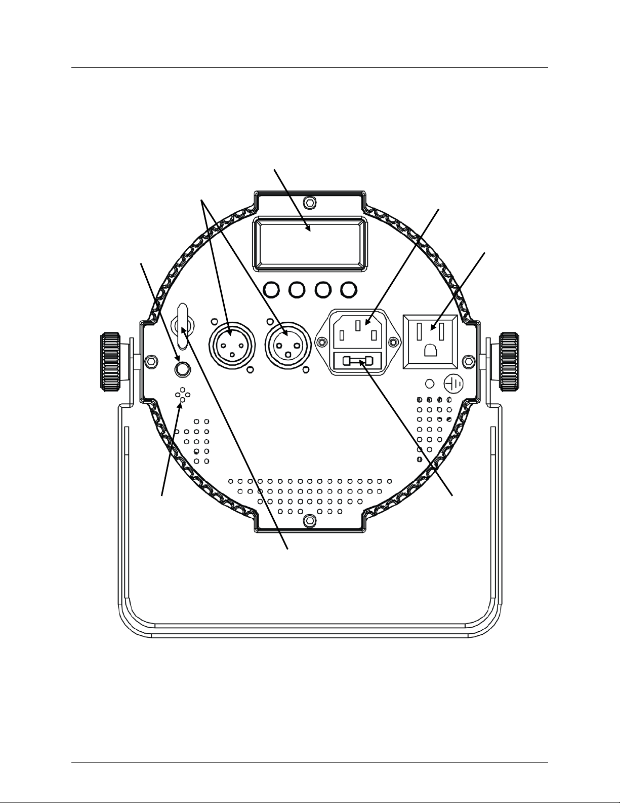
Overview
DMX In/O ut
Back Panel View
Power In
Fuse Holder
Po wer Out
Safety Loop
Microphone
Microphone
Sensitivity
Adjustment Knob
Control Panel
LED Display
SlimPAR™ QUAD 6 IRC User Manual Rev. 2 Page 5 of 17
Page 6
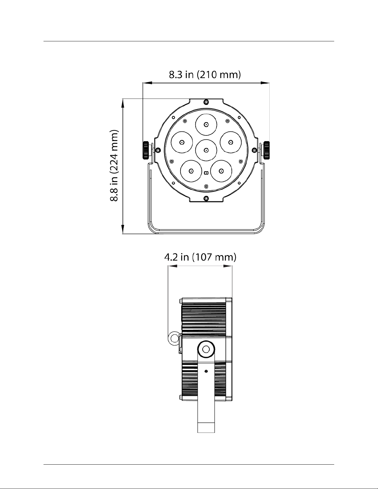
Dimensions
Page 6 of 17 SlimPAR™ QUAD 6 IRC User Manual Rev. 2
Page 7

AC Power
ranging power supply and it can work with an
Fuse
Installed fuse
(held by plastic clip)
Spare fuse holder
(inside safety cap)
Safety cap
3. SETUP
The SlimPAR™ QUAD 6 IRC has an autoinput voltage range of 100~240 VAC, 50/60 Hz.
To determine the product’s power requirements (circuit breaker, power outlet, and
wiring), use the current value li sted on the label affixed to the product’s back panel, or
refer to the product’s specifications chart. The listed current rating indicates the
product’s average current draw under normal condition s.
Always connect the product to a protected circuit (circuit breaker or fuse). Make
sure the product has an appropriate electrical ground to avoid the risk of
electrocution or fire.
Never connect the product to a rheostat (variable resistor) or dimmer circuit, even
if the rheostat or dimmer channel serves only as a 0~100% switch.
Replacement
Disconnect the product from power before replacing the fuse.
1. Disconnect the product from power.
2. Wedge t he tip of a flat-head scre w drive r into the slot of the fuse holder.
3. Pry the fuse holder out of the housing.
4. Remove the blown fuse from the holder.
5. Replace with a fuse of the exa ct same type and rating.
6. Insert the fus e holder ba ck in place and reconnect power.
A spare fuse is not included; however, the saf ety cap has room for a spare.
Always replace a blown fuse with t he sam e type and rat ing.
SlimPAR™ QUAD 6 IRC User Manual Rev. 2 Page 7 of 17
Page 8

Power Linking
Power Linking
3rd Product
1st Product
Other Products
The product provides power linki ng via the IEC outlet located in the back of the unit.
Diagram
2nd Product
You can power link up to 39 SlimPAR™ QUAD 6 IRC units on 1 20 VAC or up to 75
SlimPAR™ QUAD 6 IRC units on 230 VAC.
The power linking diagram shown above corresponds to the North American
version of the product ONLY! If using the product in other markets, you must
consult with the local CHAUVET® distributor as power linking connectors and
requirements may differ in your country or region.
Page 8 of 17 SlimPAR™ QUAD 6 IRC User Manual Rev. 2
Page 9

Mounting
, read and follow the safety recommendations indicated in
Rigging
Mount the
surface mounting.
Double-Bracketed
Yoke
Before mounting the product
the Safety Notes.
Orientation
The SlimPAR™ QUAD 6 IRC may be mounted in any position; however, make sure
adequate ventilation is provided around the product
• Before deciding on a location, always make sure there is easy access to the product
for maintenance and programming.
• Make su re th at th e str uctur e or surface onto which you are m ounting the product
can support the product’s weight (see the Technical Specifications
).
• When mounting the product overhead, always use a safety cable.
product securely to a rigging p oint , such as an elevated plat form or a tr uss.
• When rigging the product onto a truss, you should use a mounting clamp of
appropriate weight capacity. The brackets have a 13-mm hole, which is appropriate
for this purpose.
• When power linking multiple products, you must al way s cons id er th e leng th of th e
power linking cable and mount the products close enough for the cable to reac h.
• The bracket adjustment knobs allow for directional adjustment when aiming the
product to the desired angle. Only loosen or tighten the bracket knobs manually.
Using t ools could damage the knobs.
• The double-bracketed yoke also serves as floor supports for
When mounting the product on the floor, make sure that the product and cables ar e
away from people and vehicles.
Mounting
Clamp
Safety Cable
Mounting Diagram
Bracket Adjustment
Knob
SlimPAR™ QUAD 6 IRC User Manual Rev. 2 Page 9 of 17
Page 10

Control Panel
Operation
To access the control panel functions, use the four buttons located underneath the
Button
Function
<UP>
Menu Map
P 1
P 2
4-col or program (fading)
P 4
4-CH
8-CH
8-channel DMX mode
C 3
Blue
C 6
Purple
C 10
Light Green
C 11
Violet
C 12
Yellow
C 13
Pink
R 1~R100
Red
4. OPERATION
display.
<MENU> Selects an operation mode or to backs out of the curr ent menu option
Scrolls up the li st of opti ons or selec ts a high er val ue
<DOWN> Scrolls do wn the list of options or sel ects a lower value
<ENTER> Activates a menu option or a selected value
Mode Programming Steps Description
4-col or program (sw i tching)
P
(Auto Program)
P 5
P 6 15-color program (sound-active)
C 1 Red
C 2 Green
C 4 Amber
C 5 Cyan
C
(Preset Colors)
S S001~S100 Program speed of P1~P4
C 7 Yellow
C 8 White (RGB)
C 9 Orange
C 14 Light Blue
C 15 Whit e (RGBA)
P 3 15-color program (switching)
15-color program (fading)
(VOL1~VOL4)
For use with IRC
d001~d505
4-col or program (sound-active)
4-channel DMX mode (RGBA)
Static color
U--
SET
Page 10 of 17 SlimPAR™ QUAD 6 IRC User Manual Rev. 2
G 1~G100 Green
b 1~b100 Blue
A 1~A100 Amber
ON
OFF
Each custom stati c color 0~100%
Com bines Red, Green , Blue, and
Amber
Turns infrared on or off
Page 11

Configuration
uses. If you choose a starting address that is too high, you could
CH DMX mode, which
DMX Channel Modes, Assignments, and Values
1
Red
000 ó 255
0~100% 2
Green
000 ó 255
0~100%
3 Blue
000 ó 255
0~100%
4 Amber
000 ó 255
0~100%
Color Macros
000 ó 015
No function
016 ó 255
Color macros
6 Speed
(When Ch. 7 is 032~233)
000 ó 015
No function
016 ó 255
Slow~fast
000 ó 031
RGBA mode
032 ó 063
Pulse effect 0~10 0 %
064 ó 095
Pulse effect 100% ~ 0
096 ó 127
Pulse effect 100% ~0~100%
128 ó 159
Auto fade transition
160 ó 191
Auto snap transition (4 colors)
192 ó 223
Auto snap transition (15 colors)
224 ó 255
Sound-acti v e m ode
8 Dimmer
000 ó 255
0~100%
1
Red
000 ó 255
0~100% 2
Green
000 ó 255
0~100%
3 Blue
000 ó 255
0~100%
4 Amber
000 ó 255
0~100%
Set the p r oduct in DM X mod e to con trol with a DMX controller.
(DMX)
1. Connect the product to a suitable power outlet.
2. Turn the product on.
3. Connect a DMX cabl e from the DMX out put of the DMX controll er to the DMX input
socket on the product.
Starting Add ress
8-Channel
Wh en selec ting a s tart ing DMX addres s, alw ays co nsider the num ber of DMX cha nnels
the selected DMX mo de
restrict the access to some of the product ’s channels.
The SlimPAR™ QUAD 6 IRC uses up to 8 DMX channels in its 8defines the highest configurable address to 505.
If unfamiliar wit h DMX, downlo a d th e DMX Primer from www.chauvetlighting.com.
To select the starting address, do the following:
1. Press <MENU> repeatedly unt i l 4-CH or 8-CH shows on the dis play.
2. Use <UP> or <DOWN> to select 4-CH or 8-CH.
3. Press <ENTER>.
4. Use <UP> or <DOWN> to sel ect t he st arting addres s.
5. Press <ENTER>.
Channel Function Value Setting
5
(Overrides Chs. 1~4)
000 ó 255 Slow~fast
SlimPAR™ QUAD 6 IRC User Manual Rev. 2 Page 11 of 17
Strobe
7 Mode
4-Channel
Channel Function Value Setting
Page 12

Configuration
Active
Turn the music on and adjust the mi crophone sensitivity knob until the unit responds
to adjust the duration of each step of the automatic program
Static Mode
(Standalone)
Set the product in one of the standal one modes to control without a DMX controller.
1. Connect the product to a suitable power outlet.
2. Turn the product on.
Never connect a product that is operating in any standalone mode (either Static,
Automatic, or Sound) to a DMX string connected to a DMX controller. Products in
standalone mode may transmit DMX signals that could interfere with the DMX
signals from the controller.
Sound-
Mode
Automatic Mode
To enable the Sound-Active mode, do the following:
1. Press <MENU> repeatedly unt i l P 1~P 6 shows on the display.
2. Press <ENTER>.
3. Use <UP> or <DOWN> to select P 5 or P 6.
4. Press <ENTER>.
5.
to the beat of the music.
The product will only respond to low frequencies of music (bass and drums). If
there is no sound, the product will turn off.
To enable the Automatic mode, do the following:
1. Press <MENU> repeatedly unt i l P 1~P 6 shows on the display.
2. Press <ENTER>.
3. Use <UP> or <DOWN> to select P 1~P 4.
4. Press <ENTER>.
5. Press <MENU> repeatedly unt i l S 1~S100-- shows on the display.
6. Use <UP> or <DOWN>
from S 1 (slow) to S100 (fast).
7. Press <ENTER>.
To enable the Static mode, do the foll owing:
1. Press <MENU> repeatedly unt i l C 1~C 15 shows on the display.
2. Press <ENTER>.
3. Use <UP> or <DOWN> to s elect the pres et color ( C 1~C 15).
4. Press <ENTER>.
Custom Static
Colors
To enable the Custom Static Colors m ode, do the foll owi ng:
5. Press <MENU> repeatedly unt i l U-- shows on the display.
6. Press <ENTER> and one of the following colors shows on the display: RXXX (red),
GXXX (green), bXXX (blue) or AXXX (amber)
7. Press <ENTER> repeat edly to select the d esired c olor.
8. Use <UP> or <DOWN> to select the desired color value (0~100).
NOTE: Selecting 0 will turn the c olor of f.
9. Press <ENTER> to select co lor v alue a nd co ntinue to t he next color.
10. Repeat steps 3 to 5 until you create your desired c olor.
Page 12 of 17 SlimPAR™ QUAD 6 IRC User Manual Rev. 2
Page 13

Master/Slave
QUAD 6 IRC unit (the “master”) to
QUAD 6 IRC units (the “slaves”) without
the need of a DMX controller. The master unit will be set to operate in either Automatic
Active m ode, while the slave units will be set to operate in Slave mode. Once
Infrared Remote
The SlimPAR™ Q UAD 6 IRC is fully compatible with the Infrared Remote Control (IRC)
The Master/Slave m ode allows a single SlimPAR™
Mode
control the actions of one or more SlimPAR™
or Sound-
set and connected, the slave units will operate in unison with the master unit.
Configure the units as indicated below.
Slave un its:
1. Press <MENU> repeatedly unt i l 4-CH or 8-CH shows on the dis play.
2. Press <ENTER> to accept.
3. Set th e D M X address to d 1.
4. Connect the DMX input of the first slave unit to t he DMX output of the master unit.
5. Connect the DMX input of the subsequent slave units to the DMX output of the
previous slave uni t.
6. Finish setting and connecting all the slave units.
Master unit:
1. Set th e m aster unit to opera te i n either Automa t ic or Sound mode.
2. Make the master unit the first unit in the DMX daisy chain.
• Configure all the slave unit s before connecting the master unit to the DMX
daisy chain.
• Never connect a DMX controller to a DMX string configured for Master/Slave
operation because the controller may interfere wit h the signals from the
master unit.
• Do not connect more than 31 sl ave units to the master unit.
Control
1. Press <MENU> repeatedly unt i l SET shows on the display.
2. Press <ENTER> to accept.
3. Press <UP> or <DOWN> to sel ect ON or OFF.
4. Press <ENTER>.
from CHAUVET®. To enable usage with the IRC, do the following:
SlimPAR™ QUAD 6 IRC User Manual Rev. 2 Page 13 of 17
Page 14

IRC (Infrared Remote
Control) Operation
Automatic Mode
Automatic mode will enable you to run the automatic pr ograms on t he
product.
To turn o n Automatic mode:
1. Press <AUTO> on the IRC.
2. Press <+> or <–> to choose between the different auto programs.
To a djust the speed of the automatic progr am:
1. Press <SPEED> on the IRC.
2. Press <%>.
3. Press <+> or <–> to either increase or decrease the speed of the
program.
Sound-Active Mode
Sound-Active mode will ena ble the product to respond to the music.
To turn on Sound-Active mode:
1. Press <SOUND> on the IRC.
To adjust sound sensitivity in Sound-Active mode:
1. Press <SENSITIVITY> on the IRC.
2. Press <%>.
3. Press <+> or <–> to either increase or decrease sound sensitivity.
Manual C olor C ontrol
To c hoos e a specific color with the IR C :
1. Press <MANUAL> on the IRC.
2. Press any number between 0~9 to choose your color.
To manually control the RGB percentage:
1. Press <MANUAL> on the IRC.
2. Press <R> (red), <G> (green), or <B> (blue) to choose your color.
3. Press <+> or <–> to increase or decrease the percentage of each color.
Miscellaneous Operation
To adjust the str obe rate of the program:
1. Press <STROBE> on the IRC.
2. Press <+> or <–> to in crease or decr ease t he str obe r ate.
3. Press <STROBE> again to turn off the strobe.
To change the switching effect of the program:
1. Press <FADE/SNAP> on the IRC.
Fade will slowly s witc h th e effect. Snap will rapidly switch th e effect.
To black out t he lights:
1. Press <BLACK OUT> on the IRC.
This will turn off all the l ights until the button is press ed again.
NOTE: The IRC will not respond to any inputs when Black Out is activated. If
the remote does not respond when a button is pressed, try pressing
<BLACK OUT>. You may have inadvertently activated Blac k Out.
Page 14 of 17 SlimPAR™ QUAD 6 IRC User Manual Rev. 2
Page 15

Product
up reduces light output performance and can cause overheating. This can
5. TECHNICAL INFORMATION
Dust build-
Maintenance
lead to reduction of the light source’s life and m echa nical wear. To mai ntain o ptimum
performance and minimize wear, clean the product at least twice a month. However,
usage and envir onm ental c onditions contribute to i ncreased cleaning frequency.
To clean the product, follow the instructions below:
• Unplug the product from po w er.
• Wait until the product is at room temperature.
• Use a vacuum (or dry compressed air) and a sof t brush to remov e dust collected on
the external surface and vents.
• Clean the LED transparent cover with a mild soap solution, ammonia-free glass
cleaner, or isopropyl alcohol.
• Apply the solution directly to a soft, lint-free cotton clot h or a lens cleaning t i ssu e.
• Softly wipe any dirt or grime to the outside edges of the LED transparent cover.
• Gently poli sh the transparent LED cover until it is free of h aze and lint.
Alw ays dry th e transparent LED cover carefully after cleaning.
SlimPAR™ QUAD 6 IRC User Manual Rev. 2 Page 15 of 17
Page 16

Dimensions and
Length
Width
Height
Weight
8.3 in (210 mm)
4.2 in (107 mm)
8.8 in (224 mm)
4 lbs (1.8 kg)
Note: Dimensions in inches rounded to the nearest decimal digit.
Power
Power Supply Type
Range
Voltage Selection
Switching (internal)
100~240 V, 50/60 Hz
Auto-ranging
Parameter
120 V, 60 Hz
230 V, 50 Hz
Consumption
42 W
42 W
Operating current
0.3 A
0.2 A
Power linking current (units)
13.6 A (39 units)
13.6 A (75 units)
Fuse
F 2 A, 250 V
F 2 A, 250 V
Power I / O
US/Worldwide
UK/Europe
Power input connector
IEC
IEC
Power output connector
Edison
IEC
Power Cord plug
Edison (US)
Local plug
Light Source
Type
Power
Lifespan
LED
5 W
50,000 h ours
Color
Quantity
Current
Red
6
500 mA
Green
6
500 mA
Blue
6
500 mA
Amber
6
500 mA
Photo Optic
Parameter
Illuminance @ 2 m
2,393 lx
Beam angl e
20º
Field angle
34º
Thermal
Maximum External Temp.
Cooling Syste m
104° F (40° C)
Convection
DMX
I/O Connectors
Connector Type
Channel Range
3-pin XLR
XLR
4, 8
Ordering
Product Name
Item Code
UPC Number
SlimPAR™ QUAD 6 IRC
03030600
781462209483
6. TECHNICAL SPECIFICATIONS
Weight
Page 16 of 17 SlimPAR™ QUAD 6 IRC User Manual Rev. 2
Page 17

Returns
Support office and request a Return
prepared to
provide the model number, serial number, and a brief description of the cause for the
You must send the merchandise prepaid, in its original box, and with its original packing
the following information on a piece of paper
dequate
Contact Us
Fax: +44 (0)1773 511110
Email: tech@chauvetlighting.com
www.chauvetlighting.com
www.chauvetlighting.co.uk
To return a product or request support:
• In the U.S., contact CHAUVET® World Headquarters.
• In the UK or Ireland, contact CHAUVET® Europ e Ltd.
• In any other country, DO NOT contact CHAUVET®. Contact your distributor. See
www.chauvetlighting.com
for distributors outside the U.S., United Kingdom, or
Ireland.
If you live outside the U.S., United Kingdom, or Ireland, contact your distributor of
record and follow their instructions on how to return CHAUVET® products to
them. Visit our website for contact details.
Call the corresponding CHAUVET® Technical
Merchandise Authorization (RMA) number before shipping the product. Be
return.
and accessories. CHAUVET® will not issue call tags.
Clearly label the package with the RMA number. CHAUVET® will refuse any product
returned without an RMA number.
Write the RMA number on a properly affixed label. DO NOT wr ite the RM A number
directly on the box.
Before sending the product, clea rly wr ite
and place it inside the box:
• Your name
• Your address
• Your phone number
• The RM A number
• A brief description of the problem
Be su re to p ack th e product pr operl y. Any ship ping dam age res ulti ng fr om ina
packaging will be your responsibility. FedEx packing or double-boxing are
recommended.
CHAUVET® reserves the right to use its own discretion to repair or replace
returned product(s).
World Headquart ers
CHAUVET®
General Information
Address: 5200 NW 108th Avenue
Sunrise, FL 33351
Voice: (954) 577-4455
Fax: (954) 929-5560
Toll free: (800) 762-1084
Technical Support
Voice: (954) 577-4455 (Press 4)
Fax: (954) 756-8015
United Kingdom & Ireland
CHAUVET® Europe Ltd.
General Inform ation
Address: Unit 1C
Brookhill Road Industrial Estate
Pinxton, Nottingham, UK
NG16 6NT
Voice: +44 (0)1773 511115
Technical Support
Email: uktech@chauvetlighting.com
World Wide Web
SlimPAR™ QUAD 6 IRC User Manual Rev. 2 Page 17 of 17
World Wide Web
 Loading...