

Page 1

User Manual
Page 2

TABLE OF CONTENTS
1. Before You Begin............................................................................ 3
What Is Included ....................................................................................... 3
Unpacking Instruc tions .............................................................................. 3
Text Conventions ...................................................................................... 3
Icons ......................................................................................................... 3
Document Information ............................................................................... 3
Product at a Glance ................................................................................... 4
Safety Notes ............................................................................................. 4
2. Introduction..................................................................................... 5
Product Overview ...................................................................................... 5
Product Dimensions .................................................................................. 6
3. Setup ............................................................................................... 7
AC Power .................................................................................................. 7
Fus e Replacemen t .............................................................................................7
Power Linking ....................................................................................................8
Mounting ................................................................................................... 9
Orientation .........................................................................................................9
Rigging ..............................................................................................................9
4. Operation ...................................................................................... 10
Control Panel Operation .......................................................................... 10
Menu Map ............................................................................................... 10
DMX Operation ....................................................................................... 11
Starting Address .............................................................................................. 11
Standalone Oper ation.............................................................................. 12
Master/Slave Mode (Sound-Active, Auto Mode) ................................................ 12
Automatic-Slow ................................................................................................ 12
Automatic-Fast ................................................................................................. 12
Sound-Active ................................................................................................... 12
Service Mode .......................................................................................... 13
Hidden Menu Map ............................................................................................ 13
DMX Channel Assignments and Values................................................... 14
8-Channel Mode .............................................................................................. 14
5-Channel Mode .............................................................................................. 16
5. Techni cal Information .................................................................. 17
General Maintenance .............................................................................. 17
General Troubleshooting ......................................................................... 18
Returns Procedure .................................................................................. 19
Claims ..................................................................................................... 19
Contact Inf ormati on ................................................................................. 19
6. Techni cal Sp eci f ication s .............................................................. 20
Page 2 of 20 Intimid ator™ Scan LED 2 00 User Manual R ev. 5
Page 3

1. BEFORE YOU BEGIN
What Is Included
Unpac ki ng Instructi o ns
Immediately upon receiving this product, carefully unpack it and check the container
in which you received it. Make sure that you have received all the parts indicated
l inside the container (this
product and any other accessory included with it) appears damaged from shipping,
or if the container shows signs of mishandling, notify the shipper immediately. In
Text Conventions
Convention
Meaning
<Menu>
1–512
A range of val u es 50/60
A set of values of w hic h on ly one can be chosen
A menu option not to be modified (for example,
showing the operating mode/current status)
Menu > Settings
ON
A value to be entered or sel ect ed
Icons
Docume nt In for m a ti o n
are subject to change without
Author
Date
Editor
Date
• 1 x Intimidator™ Scan LED 200
• 1 x Hanging Bracket with Mounting Hardware
• 1 x Power Cord
• 1 x Warranty Card
• 1 x Quick Reference Guide
above and that they are all in good condition. If the materia
addition, retain the container and all the packing material for inspection.
See the Claims section in the “Technical Information” chapter.
A key to be pressed on the fixture’s control panel
Settings
A sequence of menu options to be followed
Icon Meaning
This paragraph contains critical installation,
configu ration, or oper at i on information . Fai lure to
comply with thi s information may render the
The inform ation and spec ifications contained in this document
notic e. CHAUVET® ass umes no res ponsibil ity or liabili ty for any error s or omissions t hat may
appear in this manual.
© Copyright 2013 CHAUVET®. All rights reserved.
Printed in P.R.C.
Elec tronically publi s hed by CHAUV ET® in the Un it ed S t at es of Am erica.
fixture partially or completely inoperative, cause
damage to the fixture, or cause harm to the user.
This paragraph contains important installation or
configu ration infor m ati on. F ail ure to comply wit h
this information may prevent the fixture from
functioning correctly.
This parag raph reminds you of useful, althou gh
not critical, information.
Intimid ator™ Scan LED 2 00 User Manual Rev. 5 Page 3 of 20
A. Leon 06/11/13 T. Yeago 06/17/13
Page 4

Product at a Glance
x
P
x
P
P
P
P
x
P
Safety Notes
Use on Dimmer
Out door Use
Sound-Activated
DMX
Master/Slave
Please read the following notes carefully because they include important safety
information about the installation, usage, and maintenance of this product.
• Keep this User Manual for future consultation. If you sell this product to another
user, be su re that they al so receive th i s document.
• Alw ays make sure t hat the voltage of the outlet to which you are connect ing this
product is within the range stated on the decal or rear panel of the fixture.
• This product is for indoor use only! To prevent risk of fire or shock, do not expose
this fixture to rain or moisture.
• Make sure there are no fl am mable materi als cl ose to the unit wh ile operati ng.
• Always install this product in a location with adequate ventilation, at least 20 in (50
cm) from adjacent surfaces.
• Be sure that no ventilation slots on the unit’s housing are blocked.
• Always disconnect this product from the power source before cleaning it or
replacing the fuse.
• Make sure to replace the f use with another of t he same t y pe and rating.
• If mounting this product overhead, always secure it to a fastening device usi ng a
safety cable.
• The maximum ambient tempera ture ( Ta) is 104° F (40° C). Do not operate this
product at higher temperatures.
• In t he event of a serious op erati ng problem, stop usi ng the unit immediately.
• Nev er try t o repair this product. Repairs carried out by unskilled people can lead
to damage or malfunction. Please contact the nearest authorized technical
assistance center.
• Never connect this product to a dimmer pack.
• Make sure the power cord is not crimped or damaged.
• Never disconnect the power cord by pulling or tugging on the cord.
• Never carry a fixture from the power cord or any moving part. Always use the
mounting bracket or the handles.
• Always avoid direct eye exposure to the light sourc e when this fixt ure is o n.
Auto Programs
Auto-ranging Power Supply
Replaceable Fuse
User-Serviceable
Page 4 of 20 Intimid ator™ Scan LED 2 00 User Manual R ev. 5
Page 5
2. INTRODUCTION
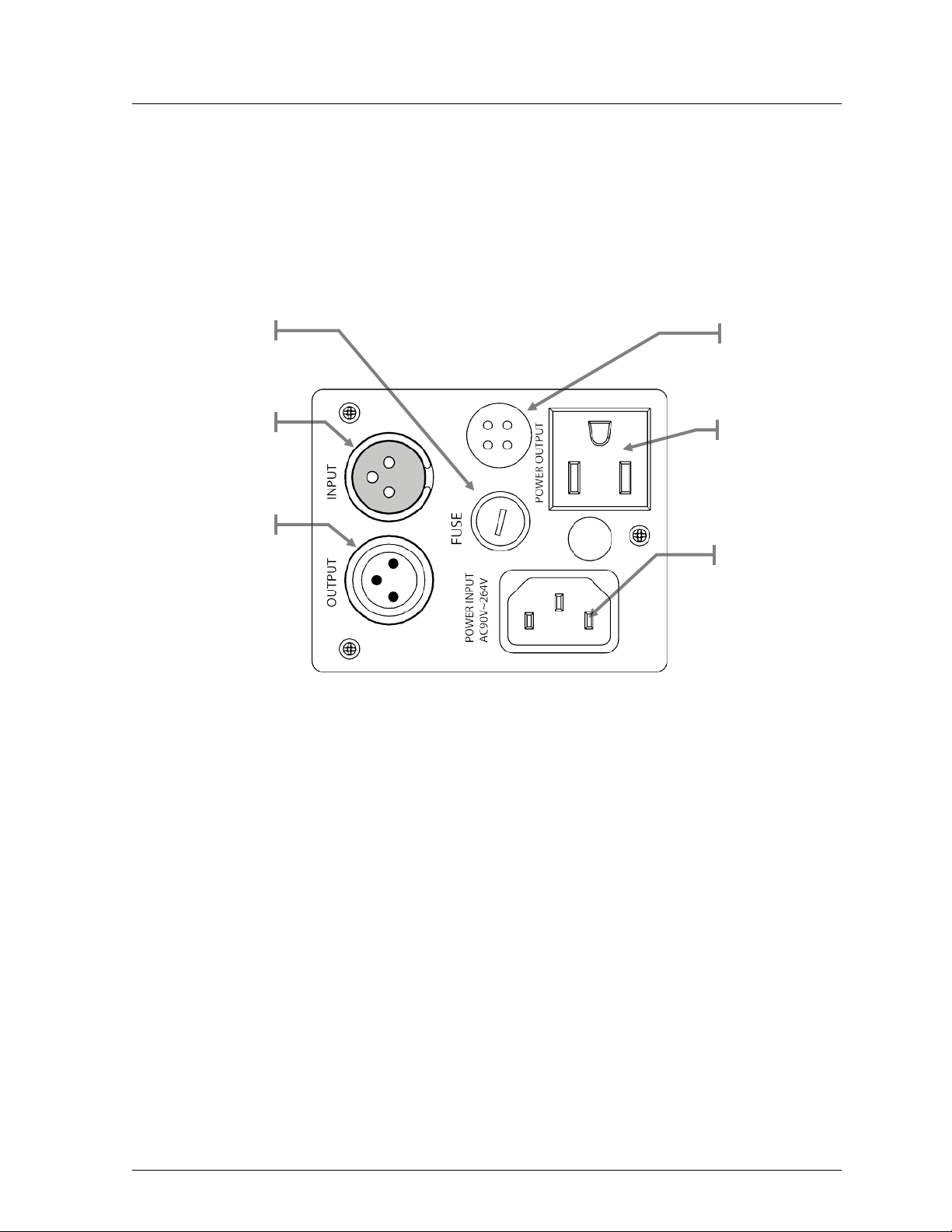
Product Overview
Power Out
DMX In
DMX Out
Power In
Microphone
Fuseholder
Intimid ator™ Scan LED 2 00 User Manual Rev. 5 Page 5 of 20
Page 6

Product Dimensions
Page 6 of 20 Intimid ator™ Scan LED 2 00 User Manual R ev. 5
Page 7
3. SETUP
AC Power
ranging power supply and it can work with an input voltage
the back plate of the fixture or refer to the fixture’s specifications chart. A fixture’s
(circuit breaker or fuse),
an appropriate electrical ground to avoid the risk of
Fuse Replacement
This product has an autorange of 100~240 VAC, 50/60 Hz.
To d eterm i n e th e pow er r equ i rem ent s for a par tic ul ar f ixt ur e, s ee th e l ab el a ff ixed to
listed current rating indicates its average current draw under normal conditions.
Always connect this product to a protected circuit
making sure that it has
electrocution or fire.
Never connect this product to a rheostat (variable resistor) or dimmer circuit,
even if the rheostat or dimmer channel serves only as a 0 to 100% switch.
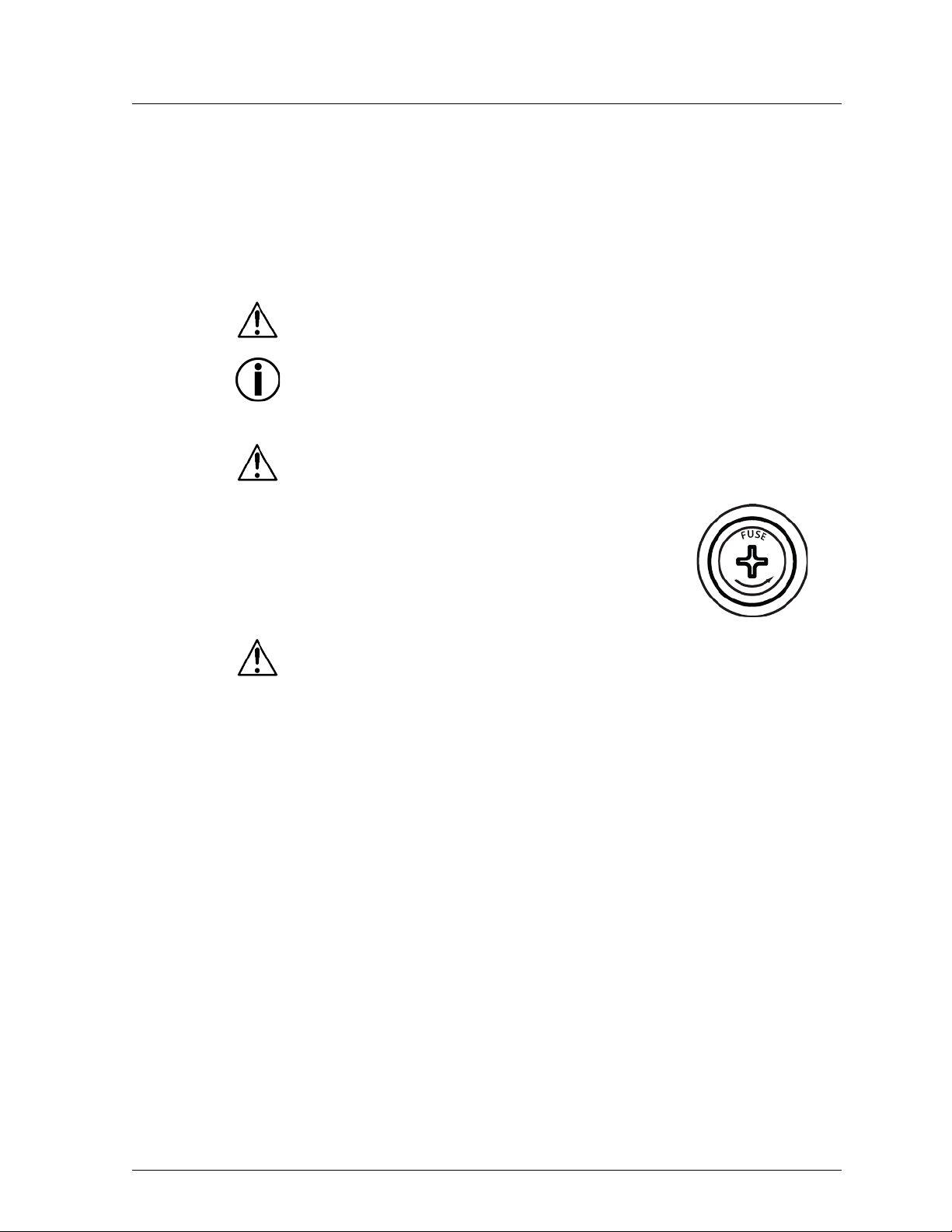
Disconnect this product from the power outlet before replacing the fuse.
1) Disconnect the fixture from the power outlet.
2) With a Phillips #2 head s crewdr iver, unscr ew the fuse
holder cap from its housing.
3) Remove the blown fuse and replace it with a good
fuse of the same type and rating (F 3. 15 A @ 250 V).
4) Sc rew th e f use hol der cap back in i ts pla ce and
reconnect power.
Always replace a blown fuse with a good fuse of the same type and rating.
Intimid ator™ Scan LED 2 00 User Manual Rev. 5 Page 7 of 20
Page 8

Power Linking
Fixture #1
Fixture #2
Fixture #3
To other fixtures
This fixture provides power linking via the Edison outlet located in the bottom of t he
unit. Pl ease see t he dia gram below for further explanation.
Power Linking
Diagram
You can power link up to 8 Intimidator™ Scan LED 200 units on 1 20 VAC.
The power linking diagram shown above corresponds to the North American
version of this product ONLY! If using this product in other markets, you must
consult with the local CHAUVET® distributor as power linking connectors and
requirements may differ in your country or region.
Page 8 of 20 Intimid ator™ Scan LED 2 00 User Manual R ev. 5
Page 9

Mounting
Orientation
may be mounted in any position, provided there is
Rigging
always consider the length of the
The bracket knobs allow for directional adjustment when aiming the fixture to the
Bracket
Bracket
Adjustment Knob
The Intimidator™ Scan LED 200
adequate room for ventilation around it.
Before deciding on a location for this product, always make sure that it will be easy to
access the unit for maintenance and programming purposes.
Make sure that the structure or surface onto which you are mounting this product can
support its weig ht . Pl ea s e se e t h e Technical Specifications sec t i o n of t his man u al f or
weight information.
When mounting this product overhead, always use a safety cable. Mount the fixture
securely to a ri gging p oint, whether an elev ated platform or a tr uss.
When rigging this product onto a truss, you should use a mounting clamp of
appropriate weight capacity. The b r acket h as a 13 mm hole, whi ch is ap pro pri at e for
this purpose.
When power linking multiple fixtures, you must
power linking cable and mount the fixtures close enough for the cable to reach them.
desired a ngle. Loosen or tighten the bracket knobs using only your bare hands. Using
tools could damage the knobs.
The double bracket yoke/mounting brackets also serve as floor supports or surface
mounting. When mounting this fixture on the floor, make sure that the fixture and its
cab les are away from people and vehicles.
Mounti ng Di a gr a m
Intimid ator™ Scan LED 2 00 User Manual Rev. 5 Page 9 of 20
Page 10

4. OPERATION
Control Panel Operation
To access the control panel functions, use the four buttons located underneath the
Press to find an operation mode
option
Press to sc roll u p t he list of
options or to find a higher value
Press to sc roll d own the list of
options or to find a lower value
Press to activate a menu option or
a selected value
Menu Map
d001~512
dis
display.
Button Function
<MODE/ESC>
or to back out of the current menu
<UP>
<DOWN>
<ENTER>
Menu Selecti on 1 Selecti on 2 Description
DM X A ddr ess
SLAv Son Standalone: Slave receive mode
Standal one Mode
Pan Invert
Tilt Invert
Display In v er t
Personality
Reset rESt
Load Default LoAd
nStS SrUn Standalone: sound-active
nAFA FASt Standalone: fast
nASL SLoU Standalone: slow
PAn Normal pan
rPAn Pan inv ert
tit Normal tilt
rtit Tilt invert
rdid Invert the display
8CH 8-channel personality
5CH 5-channel personality
DMX starting address
Normal display
Reset all m ot ors to c orr ec t an y errors
with motors misaligning during operation
Load all settings back to the factory
default
Page 10 of 20 Intimid ator™ Scan LED 2 00 User Manual R ev. 5
Page 11

DMX Operation
Starting Address
When selecting a starting DMX address, always consider the number of DMX
Set this p r oduct in DMX mode to control it with a DMX controller.
1) Connect this product to a suitable power outlet.
2) Turn this product on.
3) Connect a DMX cable from t he DMX output of t he DMX controller to the DMX
input socket of this product.
channels the selected DMX mode uses. If you choose a starting address that is too
high, you could restrict the access to some of t he fixture’s channels.
The Intimi dator™ Scan LED 200 uses up to 8 DMX channels in its 8-channel DMX
mode, which defines the highest configurable address to 505.
If you are not familiar with the DMX protocol, download the DMX Primer from
www.chauvetlighting.com.
To select the starting address, do the following:
1) Press <MODE/ESC> until d*** appears on the LED scree n.
2) Using <UP> and <DOWN>, select t he start ing ad dress (001~512).
3) Press <ENTER>.
4) Press <MODE/ESC> until one of the DMX personalities appears on the LED
screen (8-CH, 5-CH).
5) Using <UP> and <DOWN>, s elect t he desired DMX p ersona l ity.
6) Press <ENTER>.
Only connect 32 fixtures to a single DMX daisy chain!
Intimid ator™ Scan LED 2 00 User Manual Rev. 5 Page 11 of 20
Page 12

Standalone Operation
Master/Slave Mode (Sound-Active, Auto Mode)
This mode allows a single unit, the master, to operate in one of the standalone
<ENTER>
Automatic-Slow
This fixture has a preprogrammed chase that will operate in a preprogrammed, slow
via the control panel on the front of the fixture. Please see the
<ENTER>
Automatic-Fast
Access this mode via the control panel on the front of the fixture. Please see the
<ENTER>
Sound-Active
<ENTER>
modes, while one or more fixtures, slaves, synchronize their responses to the master.
Master:
The master fixture may be set in any of the STANDALONE modes: sound-active,
fast, or slow.
Slave:
1) Press <MODE/ESC> until one of the standalone modes appears on the LED
screen (SLAu, nStS, nAFA, nASL).
2) Using <UP> and <DOWN>, select SLAu.
3) Press
.
Only connect 32 fixtures to a single DMX daisy chain!
playback speed.
Access this mode
instructions below for further explanation.
1) Press <MODE/ESC> until one of the standalone modes appears on the LED
screen (SLAu, nStS, nAFA, nASL).
2) Using <UP> and <DOWN>, select nASL.
3) Press
.
This fixture has a preprogrammed chase that will operate in a preprogrammed, fast
playback speed.
instructions below for further explanation.
1) Press <MODE/ESC> until one of the standalone modes appears on the LED
screen (SLAu, nStS, nAFA, nASL).
2) Using <UP> and <DOWN>, select nAFA.
3) Press
.
This fixture has a preprogrammed, sound triggered chase.
Access this via the control panel on the front of the fixture. Please see the chart
below for further explanation.
1) Press <MODE/ESC> until one of the standalone modes appears on the LED
screen (SLAu, nStS, nAFA, nASL).
2) Using <UP> and <DOWN>, select nStS.
3) Press
.
The fixture will only respond to the low frequencies of the music (bass and
drums).
Page 12 of 20 Intimid ator™ Scan LED 2 00 User Manual R ev. 5
Page 13

Service Mode
Hidden Menu Ma p
his fixture has a hidden menu. The purpose of this menu is to adjust the home
P128
000~255
t128
000~255
9128
000~255
Adjustment for the gobo wheel
C128
000~255
Adjustment for the color wheel
H128
000~255
Y128
000~255
Adjustment for tilt
T
position (electronic adjustment) of the attributes listed below.
Main Function Selection Instruction
Adjustment for pan
Adjustment for tilt
Adjustment for pan
Please see the instructions below to access this hidden menu :
1) Press < MODE/ESC > for at least 10 seconds.
2) Using <UP/DOWN>, enter the foll owing pass code: “2323”.
3) Press <UP> to ch ange th e blinking digit in ascending ord er, and press <DOWN>
to move on to the next digit.
4) Press <ENTER>.
This mode will be automatically terminated after 15 s econds of being idle.
Intimid ator™ Scan LED 2 00 User Manual Rev. 5 Page 13 of 20
Page 14
DMX Channel Assignments and Values
8-Channel Mo de
\
Channel
Function
Value
Setting
1 Pan
000 ó 255
0°~180°
2 Tilt
000 ó 255
0°~90°
000 ó 007
192 ó 255
Open (white)
Rotate counter-clockwise (slow ~ fast)
000 ó 003
216 ó 255
Closed
Open 5
Dimmer
000 ó 255
0%~100%
000 ó 007
192 ó 255
Open
Gobo scroll: Counter-clockwise rotation
3 Color
4 Shutter
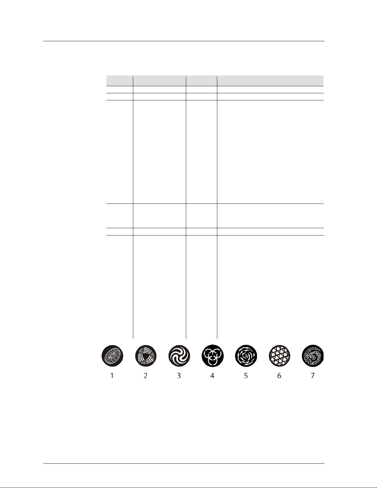
6 Gobo Wheel
008 ó 015
016 ó 023
024 ó 031
032 ó 039
040 ó 047
048 ó 055
056 ó 063
064 ó 071
072 ó 079
080 ó 087
088 ó 095
096 ó 103
104 ó 111
112 ó 119
120 ó 127
128 ó 191
004 ó 007
008 ó 215
008 ó 015
016 ó 023
024 ó 031
032 ó 039
040 ó 047
048 ó 055
056 ó 063
064 ó 071
072 ó 079
080 ó 087
088 ó 095
096 ó 103
104 ó 111
112 ó 119
120 ó 127
128 ó 191
Dark Blue
Yellow
Pink
Green
Red
Blue
Salmon Pink
White/dark blue
Dark blue/yellow
Yellow/pink
Pink/green
Green/red
Red/blue
Blue/salmon pink
Salmon pi nk /white
Rotate clockwise (slow ~ fast)
Open
Strob e (sl ow ~ f ast)
Gobo 1
Gobo 2
Gobo 3
Gobo 4
Gobo 5
Gobo 6
Gobo 7
Gobo 7 shake, fast to slow
Gobo 6 shake, fast to slow
Gobo 5 shake, fast to slow
Gobo 4 shake, fast to slow
Gobo 3 shake, fast to slow
Gobo 2 shake, (fast ó slow)
Gobo 1 shake, (fast ó slow)
Open
Gobo scroll: Clockwise rotation
Page 14 of 20 Intimid ator™ Scan LED 2 00 User Manual R ev. 5
Continues on the next page
Page 15

8-Channel
000 ó 007
160 ó 255
No function
No function
000 ó 007
248 ó 255
No function
Sound 8
Mode (Cont.)
Continued from previous page
Channel Function Value Setting
7 Function
008 ó 015
016 ó 023
024 ó 031
032 ó 039
040 ó 047
048 ó 055
056 ó 087
088 ó 095
096 ó 103
104 ó 111
112 ó 119
120 ó 127
128 ó 151
152 ó 159
Pan/tilt move-in-black
Pan/tilt move-in-black (disable)
Color wh eel m ov e-in-black
Color wh eel m ov e-in-black (disabled)
Gobo wheel m ov e-in-black
Gobo wheel m ov e-in-black (disabled)
No Function
All movem en t m ov e-in-black (disabled)
Reset pan/ til t
No Function
Reset color wheel
Reset gobo wheel
No Function
Reset a ll
8 Movement Macros
008 ó 023
024 ó 039
040 ó 055
056 ó 071
072 ó 087
088 ó 103
104 ó 119
120 ó 135
136 ó 151
152 ó 167
168 ó 183
184 ó 199
200 ó 215
216 ó 231
232 ó 247
Automatic 1
Automatic 2
Automatic 3
Automatic 4
Automatic 5
Automatic 6
Automatic 7
Automatic 8
Sound 1
Sound 2
Sound 3
Sound 4
Sound 5
Sound 6
Sound 7
Intimid ator™ Scan LED 2 00 User Manual Rev. 5 Page 15 of 20
Page 16

5-Channel Mo de
\
1 Pan
000 ó 255
0°~180° 2
Tilt
000 ó 255
0°~90°
000 ó 007
192 ó 255
Open (white)
Rotate counter-clockwise (slow ~ fast)
000 ó 003
216 ó 255
Closed
Open
000 ó 007
192 ó 255
Open
Gobo scroll: Counter-clockwise rotation
Channel Function Value Setting
3 Color
4 Shutter
5 Gobo Wheel
008 ó 015
016 ó 023
024 ó 031
032 ó 039
040 ó 047
048 ó 055
056 ó 063
064 ó 071
072 ó 079
080 ó 087
088 ó 095
096 ó 103
104 ó 111
112 ó 119
120 ó 127
128 ó 191
004 ó 007
008 ó 215
008 ó 015
016 ó 023
024 ó 031
032 ó 039
040 ó 047
048 ó 055
056 ó 063
064 ó 071
072 ó 079
080 ó 087
088 ó 095
096 ó 103
104 ó 111
112 ó 119
120 ó 127
128 ó 191
Dark Blue
Yellow
Pink
Green
Red
Blue
Salmon Pink
White/dark blue
Dark blue/yellow
Yellow/pink
Pink/green
Green/red
Red/blue
Blue/salmon pink
Salmon pi nk /white
Rotate clockwise (slow ~ fast)
Open
Strob e (sl ow ~ fast)
Gobo 1
Gobo 2
Gobo 3
Gobo 4
Gobo 5
Gobo 6
Gobo 7
Gobo 7 shake, fast to slow
Gobo 6 shake, fast to slow
Gobo 5 shake, fast to slow
Gobo 4 shake, fast to slow
Gobo 3 shake, fast to slow
Gobo 2 shake, (fast ó slow)
Gobo 1 shake, (fast ó slow)
Open
Gobo scroll: Clockwise rotation
Page 16 of 20 Intimid ator™ Scan LED 2 00 User Manual R ev. 5
Page 17

5. TECHNICAL INFORMATION
General Maintenance
Dust build up reduces light output performance and can cause overheating. This can
because you could
lead to reducti on of the li ght s our ce’s life or mec hani cal w ear. To mai nt ai n o ptim um
performance and minimize wear, you should clean your lighting fixtures at least twice
a month. However, be aware that usage and environmental conditions could be
con tribu ting f actors to increase the cleaning frequency.
To clean this fixture, follow the instructions below:
• Unplug the fixture from power.
• Wai t until the fix ture is at room temperature.
• Use a vacuum ( or dry compressed ai r) and a s oft bru sh to remove dust collected
on the external surface/vents and reachable interna l compon ents.
• Clean the mirror and lens with a mild soap solution, ammonia-free glass cleaner,
or isopropyl alcohol.
• Apply the solution directly to a soft, lint free cotton cloth or a lens cleaning tissue.
• Softly drag any dirt or grime to the outside of the mirror and lens.
• Gently polish the mirror and lens until they are free of haze and lint .
• When clean ing the movable mirror, you should kee p the contact with the mirror’s
surface to a minimum to avoid scratching or damaging it.
Alw ays dry the mirro r and lens carefully after cleani ng them.
Do not spin the cooling fan/fans using compressed air
damage it/them .
Intimid ator™ Scan LED 2 00 User Manual Rev. 5 Page 17 of 20
Page 18

General Troubleshooting
Excessive load on the circuit
Make sure that the total load
breaker o r fuse nom inal c urrent
Short circuit along the power
lines
Check the power lines and
power cords
No energy on po w er outlet
Chec k power outlet
Change to another outlet
Loose or damaged power cord
Check the power cord
Blown fuse
Replace blown fuse with a good
one of the same type and rating
Internal problem
Send product for repair
Wrong starting addres s on the
Set the correct starting address
controller
Wrong DMX personality on the
Set the cor rect DMX fixture’s
Assign the faders accordingly
Wrong polarit y setting on the
DMX c ontroller
Change the signal polarity on
the controller
Loose or damaged DMX cable
Chec k the DM X cable b efore
the faulty unit
Internal problem
Send product for repair
Signal ca bles are not DM X
compatible
Replace non DMX cables with
true DMX cables
Interference with AC or radio
signals
Keep DMX cables away from
AC wi res or radio eq uipment
DMX cable too long
Install an optically coupled DMX
Too many fixtures connected
Install an optically coupled DMX
amplifi er after unit # 32
Terminator not connected
Install a terminator, as indicated
in the DMX Primer.
solutions, contact
Symptom Possible Cause Possible Acti on
Circuit breaker
or fus e keeps
blowing
Product does not
power up
Fixture does not
respond to DMX
fixture
fixture
does not exceed 80% of the
on the fixture
Use the right fader(s) on the
personality
Page 18 of 20 Intimid ator™ Scan LED 2 00 User Manual R ev. 5
Intermittent DMX
Problems
amplifi er right before the fi xture
with intermittent problems
If you still experience problems after trying the above
CHAUVET® Technical Support.
Page 19

Returns Procedure
and request a Return Merchandise Authorization (RMA) number
before shipping the fixture. Be prepared to provide the model number, serial number,
will refuse any product returned without an RMA
directly on the box. Instead, write it on a
or double-boxing is always a safe method to use.
reserves the right to use its own discretion to repair or replace
Claims
responsible for any damage incurred during shipping to this product or
report upon reception of the damaged merchandise. Failure to do so in a timely
Contact In for m a tio n
World Headquart ers
United Kingdom & Ireland
Fax: +44 (0)1773 511110
Email: tech@chauvetlighting.com
www.chauvetlighting.com
www.chauvetlighting.co.uk
The user must send the merchandise prepaid, in the original box, and with its original
packing and accessories. CHAUVET® will not issue call tags.
Call CHAUVET®
and a brief description of the cause for the return.
The user must clearly label the package with a Return Merchandise Authorization
(RMA) number. CHAUVET®
number.
DO NOT write the RMA number
properly affixed label.
Once you have r eceiv ed the RMA number, please i nclude the following information
on a piece of paper inside the box:
• Your name
• Your address
• Your phone number
• RMA number
• A brief description of the problem
Be sure to pack the fixture properly. Any shipping damage resulting from inadequate
packaging will be the customer’s responsibility. As a suggestion, proper UPS packing
CHAUVET®
returned product(s).
The c ar ri er is
any part that shipped with it. Therefore, if the received merchandise appears to have
damages caused during shipping, the customer must submit the damage report and
any related claims with the carri er, not CHAUVET®. The c ust omer must subm it t he
manner may invalidate the cus tomer’s claim with t he carrier.
For other issues such as missing components or parts, damage not related to
shipping, or concealed damage, the customer must make claims to CHAUVET®
within seven (7) days of receiving th e merchandis e.
CHAUVET®
General Inform ation
Address: 5200 NW 108th Avenue
Sunrise, FL 33351
Voice: (954) 577-4455
Fax: (954) 929-5560
Toll free: (800) 76 2-1084
Technical Supp or t
Intimid ator™ Scan LED 2 00 User Manual Rev. 5 Page 19 of 20
Voice: (954) 577-4455 (Press 4)
Fax: (954) 756-8015
World Wide Web
CHAUVET® Europe Ltd.
General Inform ation
Address: Unit 1C
Brookhill Road Industrial Estate
Pinxton, Nottingham, UK
NG16 6NT
Voice: +44 (0)1773 511115
Technical Supp or t
Email: uktech@chauvetlighting.com
World Wide Web
Page 20

6. TECHNICAL SPECIFICATIONS
Dimensions and Weight
Length
Width
Height
Weight
13.2 in (335 m m)
6.6 in (168 mm)
14.5 in (368 m m)
7.5 lbs (3.4 kg)
Note: Dimensions in inches rounded to the nearest decimal digit.
Power
Power Supply Type
Range
Voltage Selection
Switching (internal)
100~240 V, 50/60 Hz
Auto-ranging
Parameter
120 V, 60 Hz
230 V, 50 Hz
Consumption
80 W
86 W
Operating
0.7 A
0.4 A
Power linking
11 units
21 units
Power I / O
US/Worldwide
UK/Europe
Power input connector
IEC
IEC
Power output connector
Edison
Power Cord plug
Edison (US)
Local plug
Light Source
Type
Power
Lifespan
White LED
1 x 15 W
50,000 h ours
Photo Opti c
Parameter
Standard Lens
Illuminance @ 2 m
1,577 lx
Beam angl e
15º
Scan Range
Parameter
Value
Pan
180°
Tilt
90º
Thermal
Maximum External Temp.
Cooling Syste m
104° F (40° C)
Fan
DMX
I/O Connectors
Connector Type
Channel Range
3-pin XLR
Sockets
5, 8
Ordering
Product Nam e
Item Code
Item Numb er
Intimidator™ Scan LED 2 00
08020174
INTIMIDATORSCANLED200
Page 20 of 20 Intimid ator™ Scan LED 2 00 User Manual R ev. 5
 Loading...