


Senior Solutions
ISO 13485 CERTIFIED
Therapy System
SERVICE MANUAL
™
Moving
Rehabilitation
Foward™


Senior Solutions™ Therapy System
TABLE of CONTENTS
i
FOREWORD . . . . . . . . . . . . . . . . . . . . . . . . . . . . . . . . . . . . . . . . . . . . . . . . . . 1
1 THEORY OF OPERATION . . . . . . . . . . . . . . . . . . . . . . . . . . . . . . . . . . . . . 2
1.1 OVERVIEW . . . . . . . . . . . . . . . . . . . . . . . . . . . . . . . . . . . . . . . . . . . . . 2
1.2 POWER SUPPLY CIRCUITS . . . . . . . . . . . . . . . . . . . . . . . . . . . . . . . . 2
1.3 CONTROL BOARD . . . . . . . . . . . . . . . . . . . . . . . . . . . . . . . . . . . . . . . . 2
1.4 STIM BOARD . . . . . . . . . . . . . . . . . . . . . . . . . . . . . . . . . . . . . . . . . . . . 2
1.5 ULTRASOUND BOARD AND APPLICATOR COMBINATION
SYSTEMS ONLY . . . . . . . . . . . . . . . . . . . . . . . . . . . . . . . . . . . . . . . . . 2
1.6 USER INTERFACE AND ACCESSORIES . . . . . . . . . . . . . . . . . . . . . . . 2
2 SAFETY PRECAUTIONS . . . . . . . . . . . . . . . . . . . . . . . . . . . . . . . . . . . . . . 4
2.1 PRECAUTIONARY DEFINITIONS. . . . . . . . . . . . . . . . . . . . . . . . . . . . 4
A. Caution . . . . . . . . . . . . . . . . . . . . . . . . . . . . . . . . . . . . . . . . . . . . . . . . 4
B. Warning . . . . . . . . . . . . . . . . . . . . . . . . . . . . . . . . . . . . . . . . . . . . . . . 4
C. Danger . . . . . . . . . . . . . . . . . . . . . . . . . . . . . . . . . . . . . . . . . . . . . . . . 4
D. Dangerous Voltage . . . . . . . . . . . . . . . . . . . . . . . . . . . . . . . . . . . . . . 4
E. Biohazard . . . . . . . . . . . . . . . . . . . . . . . . . . . . . . . . . . . . . . . . . . . . . . 4
F. Corrosive . . . . . . . . . . . . . . . . . . . . . . . . . . . . . . . . . . . . . . . . . . . . . . 4
G. Spontaneous Combustion . . . . . . . . . . . . . . . . . . . . . . . . . . . . . . . . 4
H. Note . . . . . . . . . . . . . . . . . . . . . . . . . . . . . . . . . . . . . . . . . . . . . . . . . . 4
2.2 PRECAUTIONARY INSTRUCTIONS . . . . . . . . . . . . . . . . . . . . . . . . . . 5
A. Cautions . . . . . . . . . . . . . . . . . . . . . . . . . . . . . . . . . . . . . . . . . . . . . . . 5
B. Warnings . . . . . . . . . . . . . . . . . . . . . . . . . . . . . . . . . . . . . . . . . . . . . . 5
C. Dangers . . . . . . . . . . . . . . . . . . . . . . . . . . . . . . . . . . . . . . . . . . . . . . . 6
3 NOMENCLATURE . . . . . . . . . . . . . . . . . . . . . . . . . . . . . . . . . . . . . . . . . . . 7
3.1 SENIOR SOLUTIONS THERAPY SYSTEMS . . . . . . . . . . . . . . . . . . . . 7
A. Senior Solutions
Therapy Systems. . . . . . . . . . . . . . . . . . . . . . . . . . . . . . . . . . . . . . . . 7
B. Senior Solutions
Combination Therapy System . . . . . . . . . . . . . . . . . . . . . . . . . . . . . 8
C. Senior Solutions
Electrotherapy System . . . . . . . . . . . . . . . . . . . . . . . . . . . . . . . . . . 9
D. Senior Solutions
Channel 3/4 Electrotherapy Module . . . . . . . . . . . . . . . . . . . . . . 10
E. Senior Solutions
NiMH Battery Module. . . . . . . . . . . . . . . . . . . . . . . . . . . . . . . . . . . 11
F. Senior Solutions Dual Channel sEMG Module . . . . . . . . . . . . . . 12
G Senior Solutions Therapy System Cart . . . . . . . . . . . . . . . . . . . . . 13
H. Senior Solutions Operator Remote Control . . . . . . . . . . . . . . . . 14
3.2 SENIOR SOLUTIONS THERAPY SYSTEM HARDWARE AND
SOFTWARE SYMBOL DEFINITIONS . . . . . . . . . . . . . . . . . . . . . . . . 15
A. Hardware Symbols . . . . . . . . . . . . . . . . . . . . . . . . . . . . . . . . . . . . . 15
B. Software Symbols . . . . . . . . . . . . . . . . . . . . . . . . . . . . . . . . . . . . . . 15
C. Optional Accessory Symbols . . . . . . . . . . . . . . . . . . . . . . . . . . . . . 15
4 SPECIFICATIONS . . . . . . . . . . . . . . . . . . . . . . . . . . . . . . . . . . . . . . . . . . . 16
4.1 SENIOR SOLUTIONS THERAPY SYSTEM . . . . . . . . . . . . . . . . . . . . 16
A. Therapy Systems Physical Specifications . . . . . . . . . . . . . . . . . . . 16
4.2 ELECTROTHERAPY WAVEFORM SPECIFICATIONS . . . . . . . . . . . 17
A. IFC (Interferential) Traditional (4 Pole)- Figure 4.2 . . . . . . . . . . 17
B. TENS- Asymmetrical Biphasic- Figure 4.3 . . . . . . . . . . . . . . . . . . 17
C. TENS- Symmetrical Biphasic- Figure 4.4 . . . . . . . . . . . . . . . . . . . 18
D. High Voltage Pulsed Current (HVPC)- Figure 4.5 . . . . . . . . . . . . 18
E. VMS
™
- Figure 4.6 . . . . . . . . . . . . . . . . . . . . . . . . . . . . . . . . . . . . . . 19
F. IFC (Interferential) Premodulated (2p)- Figure 4.7 . . . . . . . . . . 19
G. Russian- Figure 4.8. . . . . . . . . . . . . . . . . . . . . . . . . . . . . . . . . . . . . 20
H. Microcurrent- Figure 4.9 . . . . . . . . . . . . . . . . . . . . . . . . . . . . . . . . 20
I. DC (Direct Current)- Figure 4.10 . . . . . . . . . . . . . . . . . . . . . . . . . . 20
J. VMS
™
Burst- Figure 4.11 . . . . . . . . . . . . . . . . . . . . . . . . . . . . . . . . 21
K. VMS
™
FR- Figure 4.12 . . . . . . . . . . . . . . . . . . . . . . . . . . . . . . . . . . 21
5 TROUBLESHOOTING . . . . . . . . . . . . . . . . . . . . . . . . . . . . . . . . . . . . . . . 23
5.1 THERAPY SYSTEM ERROR MESSAGES . . . . . . . . . . . . . . . . . . . . 23
5.2 THERAPY SYSTEM TESTING . . . . . . . . . . . . . . . . . . . . . . . . . . . . . 31
5.3 VISUAL INSPECTION . . . . . . . . . . . . . . . . . . . . . . . . . . . . . . . . . . . 32
5.4 LEAKAGE TESTS . . . . . . . . . . . . . . . . . . . . . . . . . . . . . . . . . . . . . . . 32
5.5 UNIT STARTUP AND FAN TESTING . . . . . . . . . . . . . . . . . . . . . . . 32
5.6 STIMULATOR TEST SYSTEM SETUP . . . . . . . . . . . . . . . . . . . . . . . 33
5.7 VMS™ MODE TEST . . . . . . . . . . . . . . . . . . . . . . . . . . . . . . . . . . . . . 34
5.8 INTERFERENTIAL MODE TEST . . . . . . . . . . . . . . . . . . . . . . . . . . . 35
5.9 PREMODULATED MODE TEST . . . . . . . . . . . . . . . . . . . . . . . . . . . . 36
5.10 RUSSIAN MODE TEST . . . . . . . . . . . . . . . . . . . . . . . . . . . . . . . . . . 37
5.11 MICROCURRENT MODE TEST . . . . . . . . . . . . . . . . . . . . . . . . . . . . 38
5.12 HIGH VOLTAGE PULSED CURRENT HVPC MODE TEST . . . . . . 39
5.13 MICROCURRENT PROBE MODE TEST . . . . . . . . . . . . . . . . . . . . . 40
5.14 ULTRASOUND TESTS . . . . . . . . . . . . . . . . . . . . . . . . . . . . . . . . . . . 42
5.15 ULTRASOUND APPLICATOR IDENTIFICATION TEST . . . . . . . . . 42
5.16 ULTRASOUND APPLICATOR OUTPUT TEST . . . . . . . . . . . . . . . . 43
5.17 ULTRASOUND DUTY CYCLE TEST . . . . . . . . . . . . . . . . . . . . . . . . 44
5.18 COMBO OPERATION TEST . . . . . . . . . . . . . . . . . . . . . . . . . . . . . . . 45
5.19 sEMG AND sEMG + ELECTRICAL STIMULATION TESTS . . . . . . 46
5.19 NiMH BATTERY MODULE CHECKS . . . . . . . . . . . . . . . . . . . . . . . . 50
6 REMOVAL/REPLACEMENT . . . . . . . . . . . . . . . . . . . . . . . . . . . . . . . . . . 52
6.1 CHANNEL 3/4 ELECTROTHERAPY AND NIMH BATTERY,
INSTALLATION AND REMOVAL. . . . . . . . . . . . . . . . . . . . . . . . . . . . 52
6.2. MODULE INSTALLATION AND REMOVAL . . . . . . . . . . . . . . . . . . 52
6.3
SEMG MODULE INSTALLATION AND REMOVAL . . . . . . . . . . . . 56
6.4 THERAPY SYSTEM SEPARATING TOP & BOTTOM . . . . . . . . . . 59
6.5 THERAPY SYSTEM FAN . . . . . . . . . . . . . . . . . . . . . . . . . . . . . . . . 61
6.6 THERAPY SYSTEM CONTROL BOARD ASSEMBLY . . . . . . . . . . 62
6.7 THERAPY SYSTEM KEYMAT ASSEMBLY . . . . . . . . . . . . . . . . . . 63
6.8 THERAPY SYSTEM CONNECTOR BOARD . . . . . . . . . . . . . . . . . 64
6.9 THERAPY SYSTEM ULTRASOUND BOARD
COMBINATION SYSTEMS ONLY . . . . . . . . . . . . . . . . . . . . . . . . 65
6.10 THERAPY SYSTEM STIM BOARD CHANNELS 1/2 . . . . . . . . 66
6.11 THERAPY SYSTEM POWER SUPPLIES . . . . . . . . . . . . . . . . . . . 67
6.12 CHANNEL 3/4 ELECTROTHERAPY MODULE
CONNECTOR BOARD . . . . . . . . . . . . . . . . . . . . . . . . . . . . . . . . . . . 69
6.13 CHANNEL 3/4 ELECTROTHERAPY MODULE STIM BOARD . . . 70
6.14 MOUNTING AND DISMOUNTING THERAPY SYSTEM AND
THERAPY SYSTEM CART . . . . . . . . . . . . . . . . . . . . . . . . . . . . . . . . 71
7 GENERAL MAINTENANCE . . . . . . . . . . . . . . . . . . . . . . . . . . . . . . . . . . 72

Senior Solutions™ Therapy System
TABLE of CONTENTS
ii
7.1 CLEANING THE SYSTEM . . . . . . . . . . . . . . . . . . . . . . . . . . . . . . . . 72
7.2 CALIBRATION REQUIREMENTS . . . . . . . . . . . . . . . . . . . . . . . . . . 72
7.3 FIELD SERVICE . . . . . . . . . . . . . . . . . . . . . . . . . . . . . . . . . . . . . . . . 72
7.4 FACTORY SERVICE . . . . . . . . . . . . . . . . . . . . . . . . . . . . . . . . . . . . . 72
8 ULTRASOUND CALIBRATION . . . . . . . . . . . . . . . . . . . . . . . . . . . . . . . 73
8.1 GENERAL . . . . . . . . . . . . . . . . . . . . . . . . . . . . . . . . . . . . . . . . . . . . . 73
9 PARTS . . . . . . . . . . . . . . . . . . . . . . . . . . . . . . . . . . . . . . . . . . . . . . . . 7479
TOP TO BOTTOM ASSEMBLY . . . . . . . . . . . . . . . . . . . . . . . . . . . . . . . . 74
COMBINATION SYSTEM BASE ASSEMBLY . . . . . . . . . . . . . . . . . . . . 75
COMBINATION STIM & ULTRASOUND PC BOARD ASSEMBLY . . . . 76
TOP HOUSING ASSEMBLY . . . . . . . . . . . . . . . . . . . . . . . . . . . . . . . . . . 77
SENIOR SOLUTIONS CONTROL BOARD ASSEMBLY . . . . . . . . . . . . . 78
CHANNEL 3/4 ELECTROTHERAPY MODULE ASSEMBLY . . . . . . . . . 79
10 SCHEMATICS . . . . . . . . . . . . . . . . . . . . . . . . . . . . . . . . . . . . . . . . . . . . . 80
SENIOR SOLUTIONS THERAPY SYSTEM- CONTROL BOARD . . . . 80-82
SENIOR SOLUTIONS THERAPY SYSTEM-
ULTRASOUND PC BOARD . . . . . . . . . . . . . . . . . . . . . . . . . . . . . . . . 83-85
SENIOR SOLUTIONS THERAPY SYSTEM- STIM BOARD . . . . . . . . 86-95
SENIOR SOLUTIONS THERAPY SYSTEM- CONNECTOR BOARD . . . . . 96
SENIOR SOLUTIONSTHERAPY SYSTEM- CHANNEL 3/4
ELECTROTHERAPY MODULE CONNECTOR BOARD . . . . . . . . . . . . . . . 97
SENIOR SOLUTIONS THERAPY SYSTEM- POWER SUPPLIES . . . . . . . 98
11 WARRANTY . . . . . . . . . . . . . . . . . . . . . . . . . . . . . . . . . . . . . . . . . . . . . . 99


1
Senior Solutions™ Therapy System
FOREWORD
Read, understand, and follow the Safety Precautions and all other information contained in this
manual.
This manual contains the necessary safety and field service information for those field service
technicians, certified by Chattanooga Group, to perform field service on the Senior Solutions Therapy
System, modules, and accessories.
At the time of publication, the information contained herein was current and up-to-date. However,
due to continual technological improvements and clinical knowledge in the fields of electrotherapy
and ultrasound, as well as Chattanooga Group’s policy of continual improvement, Chattanooga
Group reserves the right to make periodic changes and improvements to their equipment and
documentation without any obligation on the part of Chattanooga Group.
It is the sole responsibility for certified field service technicians to stay informed and trained in the
latest technology utilized in the Senior Solutions Therapy System by Chattanooga Group. From time
to time, as significant improvements are incorporated, service bulletins will be produced and made
available on our web site (chattgroup.com) in lieu of reprinting a complete manual prematurely.
These service bulletins will provide updated service information and technological improvements to
the Senior Solutions Therapy System for use by certified service technicians.
Due to the complex nature of the technology utilized by Chattanooga Group, the recommended
troubleshooting techniques are to determine “Bad Board” and board replacement only. No board
component-level troubleshooting is recommended, nor will information or parts be supplied by
Chattanooga Group.
Any board component-level troubleshooting performed will be at the sole risk and liability of the
certified field service technician performing such troubleshooting techniques. Performance of such
techniques may render the warranty null and void.
The Senior Solutions Therapy System equipment is to be used only under the prescription
and supervision of a licensed medical practitioner.
©2008 Encore Medical, L.P. and its affiliates, Austin, Texas, USA. Any use of editorial, pictorial or layout composition of this publication without express written consent from Chattanooga
Group of Encore Medical, L.P. is strictly prohibited. This publication was written, illustrated and prepared for print by Chattanooga Group of Encore Medical, L.P.

2
Senior Solutions™ Therapy System
1 THEORY OF OPERATION
1.1 OVERVIEW
The Senior Solutions Therapy System are comprised of several PC board assemblies housed within a
common enclosure. These assemblies each support a distinct function in the product. The basic elements
are User Interface, Control Board, Stim Board, Ultrasound Board, Ultrasound Applicator, and Power Supply
Circuits.
When a Module (Channel 3/4 Electrotherapy, NiMH Battery, or sEMG) is installed, the Control Board
software automatically recognizes that a Module has been installed and prompts the installer to perform
certain tasks, for verification of Module installed and to make the respective Module fully functional. No
additional software installation is required as the Therapy System contains all necessary software to
accommodate any Module installation.
1.2 POWER SUPPLY CIRCUITS
A universal input 100 Watt power supply provides the Control Board and Stim Board of the system with 24
volts DC. The supply is connected to the mains at all times when the cord is attached. The 24 VDC supply is
regulated locally at each PC board as required. On Combination Systems, a separate universal 75 Watt Power
Supply provides 24 volts DC to the Ultrasound PC Board. The 24 volt DC power is regulated at the board, as
required.
1.3 CONTROL BOARD
The Control Board serves just as its name implies. It controls the operation of the stim board, ultrasound
board, user interface, optional modules, and accessories. The control board communicates to the stim
boards and ultrasound board through a proprietary bus. The control board drives the display. The control
board reads the menu Buttons. The control board reads and manages the Multimedia (MMC) Card, Patient
Data Card, and sEMG Data Card. Sound output is generated by the control board and routed to an internal
speaker.
The control board reads the Optional Patient Interrupt Switch and the Operator Remote Control (used to
administer Manual Stimulation Therapy).
1.4 STIM BOARD
The Stim Board creates all muscle stimulation output. Communications to the Stim Board is via a
proprietary bus. A processor on the Stim Board acts on messages passed to it by the Control Board to
set up waveforms and adjust output amplitude. Information can likewise be passed from the Stim
Board back to the Control Board for monitoring Current, Microcurrent Probe Contact Quality indication,
etc. If the Stim Board does not respond as expected to a command from the Control Board, output is
STOPped and an Error Message is generated.
1.5 ULTRASOUND BOARD AND APPLICATOR COMBINATION SYSTEMS ONLY
The Ultrasound Board generates the 1 or 3.3 MHz output to drive the Sound Head of the Applicator. The
Ultrasound Board is accessed through the proprietary bus by the Control Board. It can provide current and
voltage information about the ultrasound output of the board. The calibration data for the Sound Head is
passed through the Ultrasound Board from the Applicator to the Control Board. By storing the calibration
data in the Applicator, there is no calibration necessary for the Ultrasound Board and any calibrated
Chattanooga Group Senior Solutions Therapy System Applicator can be connected and operated to
provide accurate coupling and output.
1.6 USER INTERFACE AND ACCESSORIES
The LCD display panel provides the operator visible feedback in the way of menu choices. Pressing the
menu Buttons makes selections from the menus. The control board interprets these user inputs and responds
accordingly. Audible feedback is given as well to indicate key presses and end of treatment.
The Control Board accesses the Patient Data Card, sEMG Data Card and MMC Card via an on board Reader/
Writer Interface. The voltage necessary to operate the reader is provided by the 100 Watt Power Supply and is
regulated by the Control Board.
A. Channel 3/4 Electrotherapy Module
The Channel 3/4 Electrotherapy Module creates all muscle stimulation output for Channels 3 and 4.
The Channel 3/4 Electrotherapy Module is interfaced with the System via a ribbon cable which
supplies power and facilitates communication between the Stim Board and Control Board of the
system. All waveforms available to channels 1 and 2 are available to channels 3 and 4 via the system
software. No additional software is required for full functionality of the module.

3
Senior Solutions™ Therapy System
1 THEORY OF OPERATION
1.6 USER INTERFACE AND ACCESSORIES (CONTINUED)
B. NiMH Battery Module
The NiMH Battery Module incorporates two Nickel Metal Hydride (NiMH) Battery packs and
a PC Board. The PC Board monitors the Charge Level of the Batteries. The Batteries supply 24 VDC to
the system which is then distributed to the respective pcb’s through the system power supply.
The Battery Module is interfaced with the system via a ribbon cable that facilitates communication
with the Control Board and delivery of power to a Two Channel Electrotherapy or Combination
Therapy System. When the Therapy System is connected to a Mains Power Supply via the Power
Cord, the NiMH Battery Module will charge. Once the Module is fully charged the software will STOP
the charging process eliminating the possibility of overcharging. Battery power is used only when
the Therapy System is not connected to a Mains Power Supply.
C. sEMG Module
The Surface Electromyography (sEMG) Module utilizes a PC board to communicate to the Stim and
Control Boards via direct PC Board Contacts. The sEMG module reads and transmits muscle activity
through lead wires and electrodes. The sEMG Module communicates muscle activity data to the Control
Board which can store the data on an sEMG Data Card via the onboard Card Reader/Writer for viewing on
a PC in graph form via the optional Chattanooga Group Patient Data Management System (PDMS)
Software and Card Reader.
D. Operator Remote Control
The Operator Remote Control is just as its name indicates and incorporates a PC Board. The Channel 1/2
Operator Remote Control is interfaced with the Therapy System through its unique connector on the
front of the Therapy System and the Channel 3/4 Electrotherapy Module. The Operator Remote Control
communicates with the Stim Board(s) to the Control Board for the administration of Manual Stim Therapy
only.
E. Therapy System Cart
The Therapy System Cart is designed for use with the Chattanooga Group Therapy System only. The
cart alone provides mobility to the Therapy System and storage of necessary accessories and supplies
used in conjunction with the Therapy System.
4
Senior Solutions™ Therapy System
2 SAFETY PRECAUTIONS
The precautionary instructions found in this
section and throughout this manual are indicated
by specific symbols. Understand these symbols
and their definitions before operating this
equipment.
Text with a “CAUTION” indicator will explain
possible safety infractions that could have the
potential to cause minor to moderate injury or
damage to equipment.
Text with a “WARNING” indicator will explain
possible safety infractions that will potentially
cause serious injury and equipment damage.
Text with a “DANGER” indicator will explain
possible safety infractions that are imminently
hazardous situations that would result in death
or serious injury.
Text with a “Dangerous Voltage” indicator serves
to inform the technician of possible hazards
resulting in the electrical charge disbursement
from certain components if handled or serviced
improperly.
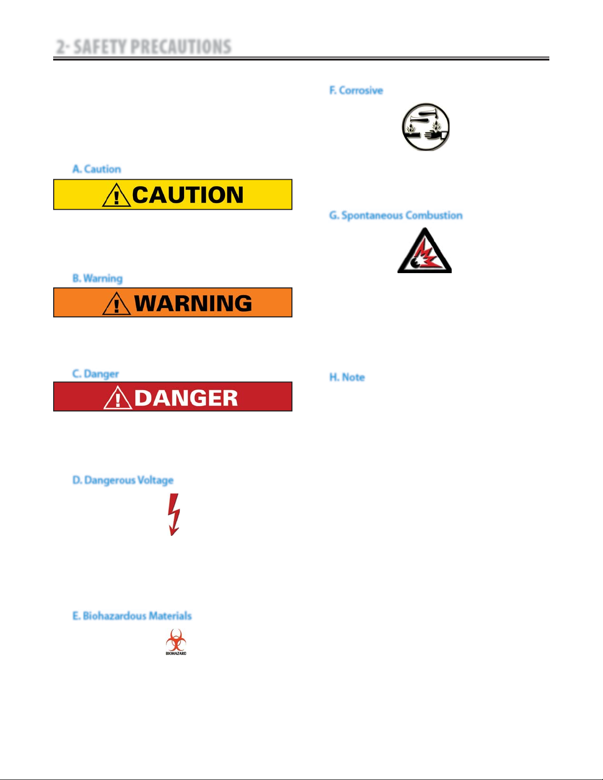
2.1 PRECAUTIONARY DEFINITIONS
A. Caution
B. Warning
C. Danger
D. Dangerous Voltage
E. Biohazardous Materials
F. Corrosive
Text with a “CORROSIVE" indicator will explain
possible safety infractions if the chemical
components of the battery are exposed to air,
skin, or other materials.
G. Spontaneous Combustion
Throughout this manual “NOTE” may be found.
These Notes are helpful information to aid in
the particular area or function being described.
H. Note
Text with a “SPONTANEOUS COMBUSTION"
indicator will explain possible safety infractions
that could create conditions for a Spontaneous
Combustion if the material is mishandled and
not disposed of properly.
Text with a “BIOHAZARD” indicator serves to inform
the user of possible hazards resulting in improper
handling of components and accessories that have
come in contact with bodily fluids.

5
Senior Solutions™ Therapy System
2 SAFETY PRECAUTIONS
2.2 PRECAUTIONARY INSTRUCTIONS
Read, understand, and practice the precautionary and
operating instructions. Know the limitations and hazards
associated with using any Chattanooga Group device.
Observe the precautionary and operational decals placed on
the unit.
Do not operate this unit when connected to any unit other
than Chattanooga Group devices.
Do not operate this unit in an environment where
other devices are being used that intentionally radiate
electromagnetic energy in an unshielded manner. Portable
and mobile RF communications equipment can affect
Medical Electrical Equipment.
Inspect the condition of leadwires before each use. Any
damage could result in intermittent electrical stimulation.
DO NOT use sharp objects such as a pencil point or ballpoint
pen to operate the Buttons on the control panel as damage
may result.
Before each use, inspect Ultrasound Applicator for cracks,
which may allow the ingress of conductive fluid. Inspect
Applicator cables and associated connectors before each
use.
The Senior Solutions unit is not designed to prevent the
ingress of water or liquids. Ingress of water or liquids could
cause malfunction of internal components of the unit and
therefore create a risk of injury to the patient.
Where the integrity of the external protective earth conductor
arrangement is in doubt, equipment shall be operated from
its internal electrical power source.
DO NOT remove the cover. This may cause unit damage,
malfunction, electrical shock, fire, or personal injury. There are
no serviceable components inside the unit. If a malfunction
occurs, discontinue use, and immediately send to the factory
for service.
This equipment generates, uses and can radiate radio
frequency energy and, if not installed and used in
accordance with the instructions, may cause harmful
interference to other devices in the vicinity. However,
there is no guarantee that interference will not occur in
a particular installation. Harmful interference to other
devices can be determined by turning this equipment on
and off. Try to correct the interference using one or more
of the following: reorient or relocate the receiving device,
increase the separation between the equipment, connect
the equipment to an outlet on a different circuit from that
to which the other device(s) are connected, and consult the
factory field service technician or the Chattanooga Service
Department for help.
Nylatex® Wraps contain dry natural rubber and may cause
allergic reactions in patients with allergies to latex.
•
•
•
•
•
•
•
•
•
•
•
Ultrasound should be routinely checked before each use
to determine that all controls function normally, especially
that the intensity control does properly adjust the intensity
of the ultrasonic power output in a stable manner. Also,
determine that the treatment time control does actually
terminate ultrasonic power output when the timer reaches
zero.
This unit should be operated, transported and stored in
temperatures between 0°F and 140°F (-18°C and 60°C), with
relative humidity ranging from 30%-60%.
Handle Ultrasound Applicator with care. Inappropriate
handling of the Ultrasound Applicator may adversely affect
its characteristics.
•
•
•
Federal law restricts this device to sale by, or on the order of,
a physician or licensed practitioner. This device should be
used only under the continued supervision of a physician or
licensed practitioner.
Make certain the unit is electrically grounded by connecting
only to a grounded electrical service receptacle conforming
to the applicable national and local electrical codes.
This device should be kept out of the reach of children.
Care must be taken when operating this equipment around
other equipment. Potential electromagnetic or other
interference could occur to this or to the other equipment.
Try to minimize this interference by not using other
equipment in conjunction with it.
The safety of TENS waveforms for use during pregnancy or
birth has not been established.
TENS is not effective for pain of central origin. (This includes
headache.)
TENS should be used only under the continued supervision
of a physician or licensed practitioner.
TENS waveforms have no curative value.
TENS is a symptomatic treatment, and as such, suppresses
the sensation of pain which would otherwise serve as a
protective mechanism.
Do not drop the applicator or unit on hard surfaces. Do not
cool an overheated applicator with ice water or ice packs. Do
not allow the applicator to reach maximum temperatures
repeatedly. Do not submerge the applicator or unit in water.
All of these conditions will damage the applicator and unit.
Damage resulting from these conditions is not covered under
the warranty.
•
•
•
•
•
•
•
•
•
•
6
Senior Solutions™ Therapy System
2 SAFETY PRECAUTIONS
2.2 PRECAUTIONARY INSTRUCTIONS (CONTINUED)
DO NOT connect the unit to an electrical supply
without first verifying that the power supply is
the correct voltage. Incorrect voltage may cause
unit damage, malfunction, electrical shock, fire, or
personal injury. Your unit was constructed to operate
only on the electrical voltage specified on the
Voltage Rating and Serial Number Plate. Contact your
dealer if the unit is not properly rated.
Power Supplies retain High Voltage!
NiMH batteries contain Class E corrosive materials. In
the event of battery cell rupture or leakage, handle
battery module wearing neoprene or natural rubber
gloves. Contents of a ruptured or leaking battery can
cause respiratory irritation. Hypersensitivity to nickel
can cause allergic pulmonary asthma. Contents
of cell coming in contact with skin can cause skin
irritation and chemical burns.
•
•
•
Electronic monitoring equipment (such as ECG monitors and
ECG alarms) may not operate properly when TENS stimulation
is in use. Powered muscle stimulators should be used only
with the leads and electrodes recommended for use by the
manufacturer.
In the event that an Error message or Warning appears
beginning with a 2 or 3, immediately STOP all use of the unit
and contact the dealer or Chattanooga Group for service.
Errors and Warnings in these categories indicate an internal
problem with the unit that must be tested by Chattanooga
Group or a Field Service Technician certified by Chattanooga
Group before any further operation or use of the unit. Use of a
unit that indicates an Error or Warning in these categories may
pose a risk of injury to the patient, user, or cause extensive
internal damage to the unit.
Use of controls or adjustments or performance of procedures
other than those specified herein may result in hazardous
exposure to ultrasonic energy.
Before administering any treatment to a patient you should
become acquainted with the operating procedures for
each mode of treatment available, as well as the indications,
contraindications, warnings and precautions. Consult other
resources for additional information regarding the application
of Electrotherapy and Ultrasound.
To prevent electrical shock, disconnect the unit from
the power source before attempting any maintenance
procedures.
•
•
•
•
•
Keep electrodes separated during treatment. Electrodes in
contact with each other could result in improper stimulation
or skin burns.
Long term effects of chronic electrical stimulation are
unknown. Stimulation should not be applied over the anterior
neck or mouth. Severe spasm of the laryngeal and pharyngeal
muscles may occur and the contractions may be strong
enough to close the airway or cause difficulty in breathing.
Stimulation should not be applied transthoracically in that
the introduction of electrical current into the heart may cause
cardiac arrhythmia.
Stimulation should not be applied over swollen, infected,
and inflamed areas or skin eruptions, e.g., phlebitis,
thrombophlebitis, varicose veins, etc.
Stimulation should not be applied over, or in proximity to,
cancerous lesions.
•
•
•
•
•
Output current density is related to electrode size. Improper
application may result in patient injury. If any question arises
as to the proper electrode size, consult a licensed practitioner
prior to therapy session.
The Senior Solutions optional modules and associated accessories
are designed for use only with the Chattanooga Group
Electrotherapy and Combination unit.
Use only accessories that are specially designed for this device.
Do not use accessories manufactured by other companies
on this device. Chattanooga Group is not responsible for any
consequence resulting from using products manufactured by
other companies. The use of other accessories or cables may
result in increased emissions or decreased immunity of this
device and can degrade minimum safety.
•
•
•
Stimulus delivered by the TENS waveforms of this
device, in certain configurations, will deliver a charge
of 25 microcoulombs (μC) or greater per pulse and
may be sufficient to cause electrocution. Electrical
current of this magnitude must not flow through the
thorax because it may cause a cardiac arrhythmia.
Patients with an implanted neurostimulation device
must not be treated with or be in close proximity to
any shortwave diathermy, microwave diathermy, or
therapeutic ultrasound diathermy anywhere on their
body. Energy from diathermy (shortwave, microwave,
ultrasound) can be transferred through the implanted
neurostimulation system, can cause tissue damage,
and can result in severe injury or death. Injury,
damage or death can occur during diathermy therapy
even if the implanted neurostimulation system is
turned “off.”
Handle, clean and dispose of components and
accessories that have come in contact with bodily
fluids according to National, Local and Facility rules,
regulations and procedures.
Equipment not suitable for use in the presence of
a flammable anesthetic mixture with air, oxygen or
nitrous oxide.
Never, under any circumstances, open the Battery
Module housing or cells. Should an individual cell
from a battery become disassembled, spontaneous
combustion of the negative electrode is possible.
There can be a delay between exposure to air and
spontaneous combustion.
Charge the Battery Module according to the
instructions found in this manual. Never attempt to
charge the Battery Module on any other charging
mechanism.
Use the Battery Module only with the Senior
Solutions unit.
Do not reverse the polarity of the Battery Module.
Doing so can increase the individual cell temperature
and cause cell rupture or leakage.
Never dispose of Battery Module in fire. Never short
circuit the battery. The battery may explode, ignite,
leak or get hot causing serious personal injury.
Dispose of NiMH batteries according to national,
state and local codes and regulations.
•
•
•
•
•
•
•
•
•
•
7
Senior Solutions™ Therapy System
3 NOMENCLATURE
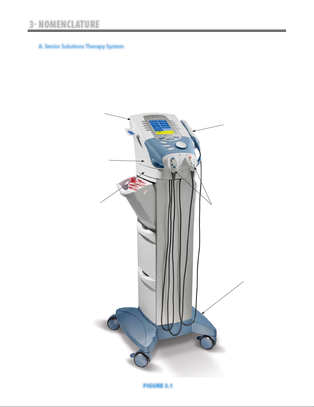
The nomenclature graphic below, Figure 3.1,
locates the major components of a two
channel combination therapy system equipped
with the following: Channel 3/4 Electrotherapy
Module, *sEMG Module, and Therapy System
Cart.
Refer to the respective pages of this section
for specific nomenclature of the optional
modules.
TWO CHANNEL COMBINATION THERAPY SYSTEM
REFER TO PAGE 8
TWO CHANNEL ELECTROTHERAPY SYSTEM
REFER TO PAGE 9
CHANNEL 3/4 ELECTROTHERAPY MODULE
REFER TO PAGE 10
OR
NIMH BATTERY MODULE
REFER TO PAGE 11
CHANNELS 1/2 AND 3/4 OPERATOR REMOTE
REFER TO PAGE 16
THERAPY SYSTEM CART
REFER TO PAGE 15
DUAL CHANNEL SEMG MODULE
REFER TO PAGE 14
INSTALLED TO BOTTOM OF THERAPY SYSTEM
3.1 SENIOR SOLUTIONS THERAPY SYSTEM
A. Senior Solutions Therapy System
ULTRASOUND APPLICATOR
FIGURE 3.1
8
Senior Solutions™ Therapy System
3 NOMENCLATURE
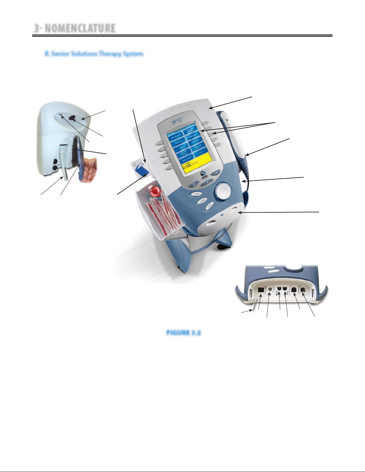
The nomenclature graphics below, Figure 3.2,
indicate the general locations of the exterior
components of the Two Channel Senior
Solutions Therapy System.
Know the components and their functions
before performing any operation of or service to
the Senior Solutions Therapy System.
Screen Contrast Control (Not functional on color
Systems)
Power On/Off Switch
Technical Maintenance Port
Main Power Cord
Rear Access Panel
Serial Decal
Two Channel Combo System
Ultrasound Applicator (5 cm
2
shown)
User Interface (Screen and Buttons)
Front Access Panel
Patient Data Card and sEMG Data Card access port
Multimedia Card (MMC) access port
1.
2.
3.
4.
5.
6.
7.
8.
9.
10.
11.
12.
Front Access Panel Lanyard
Operator Remote Control Connector
Patient Interrupt Switch Connector
Channel 1 Lead Wire Connector
Channel 2 Lead Wire Connector
Microcurrent Probe Connector
Ultrasound Applicator Connector
Therapy System to Module Ribbon Cable
13.
14.
15.
16.
17.
18.
19.
20.
3.1 SENIOR SOLUTIONS THERAPY SYSTEM (CONTINUED)
B. Senior Solutions Therapy System
FIGURE 3.2
13
14
15
16
17
18
19
2
1
3
4
5
7
8
10
12
11
9
20 BELOW
6
9
Senior Solutions™ Therapy System
3 NOMENCLATURE
7
9
11
10
8
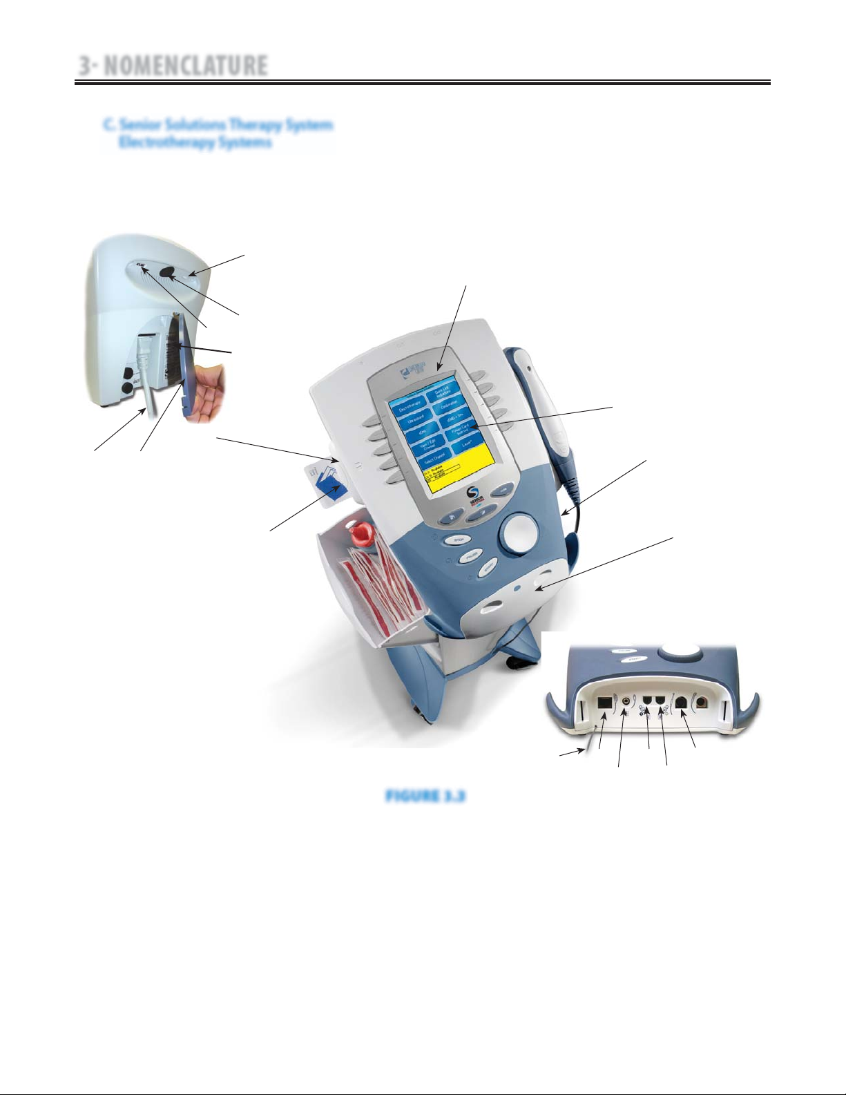
Screen Contrast Control (Not functional on Color
Systems)
Power On/Off Switch
Technical Maintenance Port
Main Power Cord
Rear Access Panel
Serial Decal
Two Channel Electrotherapy System
User Interface (Screen and Buttons)
Front Access Panel
Patient Data Card and sEMG Data Card access
port
Multimedia Card (MMC) access port
1.
2.
3.
4.
5.
6.
7.
8.
9.
10.
11.
Front Access Panel Lanyard
Operator Remote Control Connector
Patient Interrupt Switch Connector
Channel 1 Lead Wire Connector
Channel 2 Lead Wire Connector
Microcurrent Probe Connector
Therapy System to Module Ribbon Cable
12.
13.
14.
15.
16.
17.
18.
18
3.1 SENIOR SOLUTIONS THERAPY SYSTEM (CONTINUED)
C. Senior Solutions Therapy System
Electrotherapy Systems
The nomenclature graphics below, Figure 3.3,
indicate the general locations of the exterior
components of the Senior Solutions Therapy
Two Channel Electrotherapy System.
Know the components and their functions
before performing any operation of or service
to the Senior Solutions Therapy Two Channel
Electrotherapy System.
3
4
5
13
14
15
16
17
2
1
12
FIGURE 3.3
6
10
Senior Solutions™ Therapy System
3 NOMENCLATURE
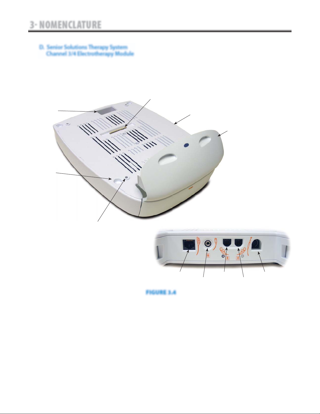
The nomenclature graphics below, Figure 3.4,
indicate the general locations of the exterior
components of the Senior Solutions Therapy
System Channel 3/4 Electrotherapy Module.
Know the components and their functions
before performing any operation of or service
to the Senior Solutions Therapy System Channel
3/4 Electrotherapy Module.
1
2
3
4
6
5
1. Two (2) Channel Electrotherapy Module
2. Extended Front Access Panel
3. Module to System Mounting Holes
4. Module to System Feet Alignment Indents
5. Power Cord Routing Port
6. Module to System Connector
7. Operator Remote Control Connector
8. Patient Interrupt Switch Connector
9. Channel 3 Lead Wire Connector
10. Channel 4 Lead Wire Connector
11. Microcurrent Probe Connector
Also Included:
Four 4 mm X 20 mm mounting screws
Channel 3 and 4 Lead Wires
Sample of Dura-Stick™ II Electrodes
NOTE:
The Channel 3/4 Electrotherapy Module is not
operable unless it is properly connected to a Senior
Solutions Therapy System.
•
•
•
7
8
9
10
11
3.1 SENIOR SOLUTIONS THERAPY SYSTEM (CONTINUED)
D. Senior Solutions Therapy System
Channel 3/4 Electrotherapy Module
FIGURE 3.4
11
Senior Solutions™ Therapy System
3 NOMENCLATURE
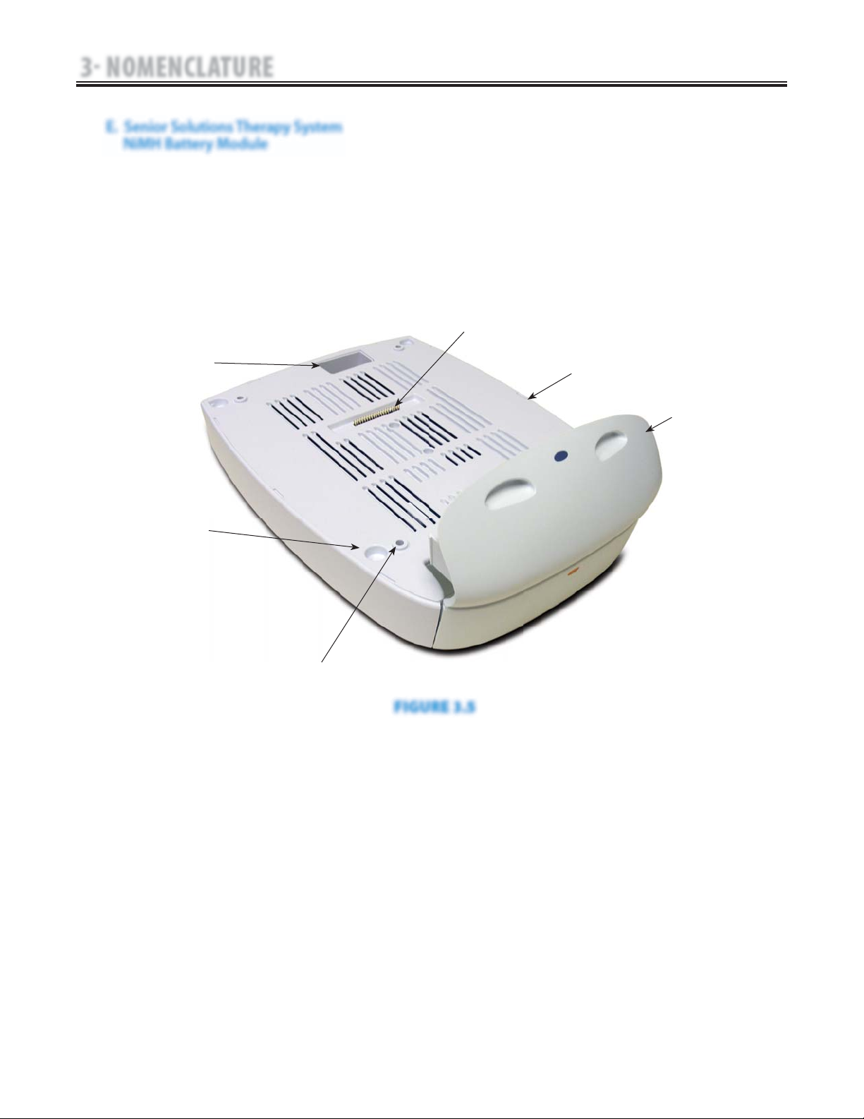
The nomenclature graphic below, Figure 3.5,
indicates the general locations of the exterior
components of the Senior Solutions Therapy
System NiMH Battery Module.
Know the components and their functions
before performing any operation of or service
to the Senior Solutions Therapy System NiMH
Battery Module.
3.1 SENIOR SOLUTIONS THERAPY SYSTEM (CONTINUED)
E. Senior Solutions Therapy System
NiMH Battery Module
1
2
3
4
6
5
1. NiMH Battery Module
2. Extended Front Access Panel
3. Module to System Mounting Holes
4. Module to System Feet Alignment Indents
5. Power Cord Routing Port
6. Module to System Connector
NOTE:
The NiMH Battery Module is not operable unless it
is properly connected to a Senior Solutions Therapy
System.
FIGURE 3.5
12
Senior Solutions™ Therapy System
3 NOMENCLATURE
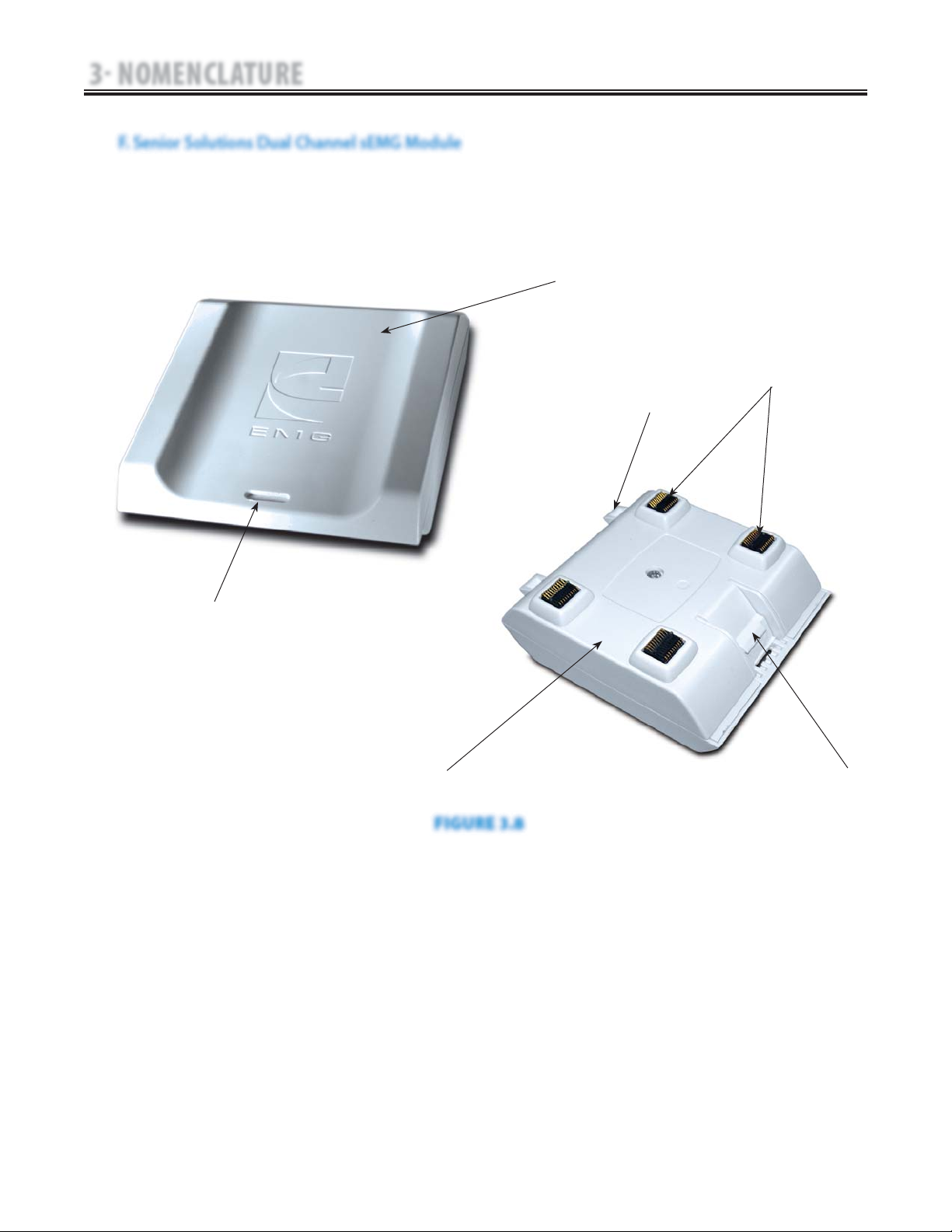
The nomenclature graphics below, Figure 3.8,
indicate the general locations of the exterior
components of the Senior Solutions Therapy
System Dual Channel sEMG Module.
Know the components and their functions
before performing any operation of or service
to the Senior Solutions Therapy System Dual
Channel sEMG Module.
1. sEMG Module Top Housing
2. Module Removal Slot
3. Module to System Mounting Tabs
4. Module to System PC Board Contacts
5. Module to System Retaining Tab
6. sEMG Module Bottom Housing
NOTE:
The Senior Solutions Dual Channel sEMG Module
is not operable unless it is connected to the Senior
Solutions Therapy System.
1
2
3
4
5
6
3.1 SENIOR SOLUTIONS THERAPY SYSTEM (CONTINUED)
F. Senior Solutions Dual Channel sEMG Module
FIGURE 3.8

13
Senior Solutions™ Therapy System
3 NOMENCLATURE
The nomenclature graphics below, Figure 3.9,
indicate the general locations of the exterior
components of the Senior Solutions Therapy
System Cart.
Know the components and their functions
before performing any operation of or service to
the Senior Solutions Therapy System Cart.
1. Cart Top
2. System to Cart Retaining Screw (4)
3. Storage Bins (6)
4. Cart Rear Swivel Casters
5. Cart Base
6. Cart Front Swivel, Locking Casters
7. Cart Bottom Access Plate
8. Front and Rear Cart Extrusions
1
2
3
4
5
6
8
7
FIGURE 3.9
3.1 SENIOR SOLUTIONS THERAPY SYSTEM (CONTINUED)
G. Senior Solutions Therapy System Cart

14
Senior Solutions™ Therapy System
3 NOMENCLATURE
The nomenclature graphics below, Figure 3.10,
indicate the general locations of the exterior
components of the Senior Solutions Therapy
System Operator Remote Control.
Know the components and their functions
before performing any operation of or service to
the Senior Solutions Therapy System Operator
Remote Control.
1. Operator Remote Storage Hook
2. Treatment PAUSE Button
3. Channel 2 Increase Intensity Button
4. Channel 2 Decrease Intensity Button
5. Manual Stimulation Button
6. Channel 1 Decrease Intensity Button
7. Channel 1 Increase Intensity Button
NOTE:
The Senior Solutions Operator Remote Control is not
operable unless it is properly connected to the Senior
Solutions Therapy System.
* Blue Button for Channels 1/2 Operator Remote Control
Orange Button for Channels 3/4 Operator Remote Control
M
INCREASE
INTENSITY
DECREASE
INTENSITY
PAUSE
TREATMENT
MANUAL
STIMULATION
Operator Remote Control Symbol Definitions
3.1 SENIOR SOLUTIONS THERAPY SYSTEM (CONTINUED)
H. Senior Solutions Operator Remote Control
FIGURE 3.10
1
2*
3
4
6
5
7
15
Senior Solutions™ Therapy System
3 NOMENCLATURE
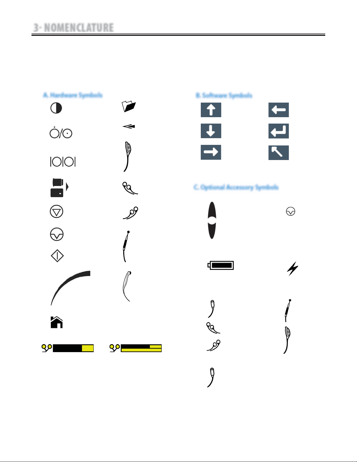
The symbol below are found on the system as
well as within the software. These symbols are
defined below for the purpose of recognition
and functionality when operating or performing
service on a Senior Solutions Therapy System,
Modules, and Accessories.
Know the symbols and their definitions before
performing any operation of or service to the
Senior Solutions Therapy System, Modules, or
Accessories.
ON/OFF
SWITCH
DATA
PORT
MULTIMEDIA AND
PATIENT + SEMG DATA
CARD
STOP
TREATMENT
PAUSE
TREATMENT
START
TREATMENT
THERAPY
INTENSITY
CONTROL
CHANNEL 1/2
OPERATOR
REMOTE
CONTROL
OPTIONAL
PATIENT
INTERRUPT
SWITCH
CHANNEL 1
LEAD WIRES
CHANNEL 2
LEAD WIRES
MICROCURRENT
PROBE
ULTRASOUND
APPLICATOR
HOME
CLINICAL
RESOURCES
LIBRARY
BACK
CONTRAST CONTROL
3.2 SENIOR SOLUTIONS THERAPY SYSTEM HARDWARE AND SOFTWARE SYMBOL DEFINITIONS
A. Hardware Symbols
MOVE UP
MOVE DOWN
MOVE RIGHT
MOVE LEFT
ACCEPT AND
RETURN
DO NOT ACCEPT
AND RETURN
B. Software Symbols
1. Operator Remote Control Symbols
M
INCREASE
INTENSITY
DECREASE
INTENSITY
PAUSE
TREATMENT
MANUAL
STIMULATION
2. NiMH Battery Module Symbols
CHARGE LEVEL
BATTERY
CHARGING
3. Channel 3/4 Electrotherapy Module Symbols
CHANNEL 3
LEAD WIRES
CHANNEL 4
LEAD WIRES
CHANNEL 3/4
OPERATOR
REMOTE
CONTROL
OPTIONAL
PATIENT
INTERRUPT
SWITCH
C. Optional Accessory Symbols
MICROCURRENT
PROBE
PAD CONTACT QUALITY
SINGLE CHANNEL GRAPH
PAD CONTACT QUALITY
DUAL CHANNEL GRAPH
4. Patient Interrupt Switch
16
Senior Solutions™ Therapy System
4 SPECIFICATIONS
The specifications found in this section provide
physical details of the Senior Solutions Therapy
System. This section also provides waveform
specifications to aid in troubleshooting.
Refer to this section when performing
troubleshooting, replacement, and repair of a
Senior Solutions Therapy System, Modules, and
Accessories.
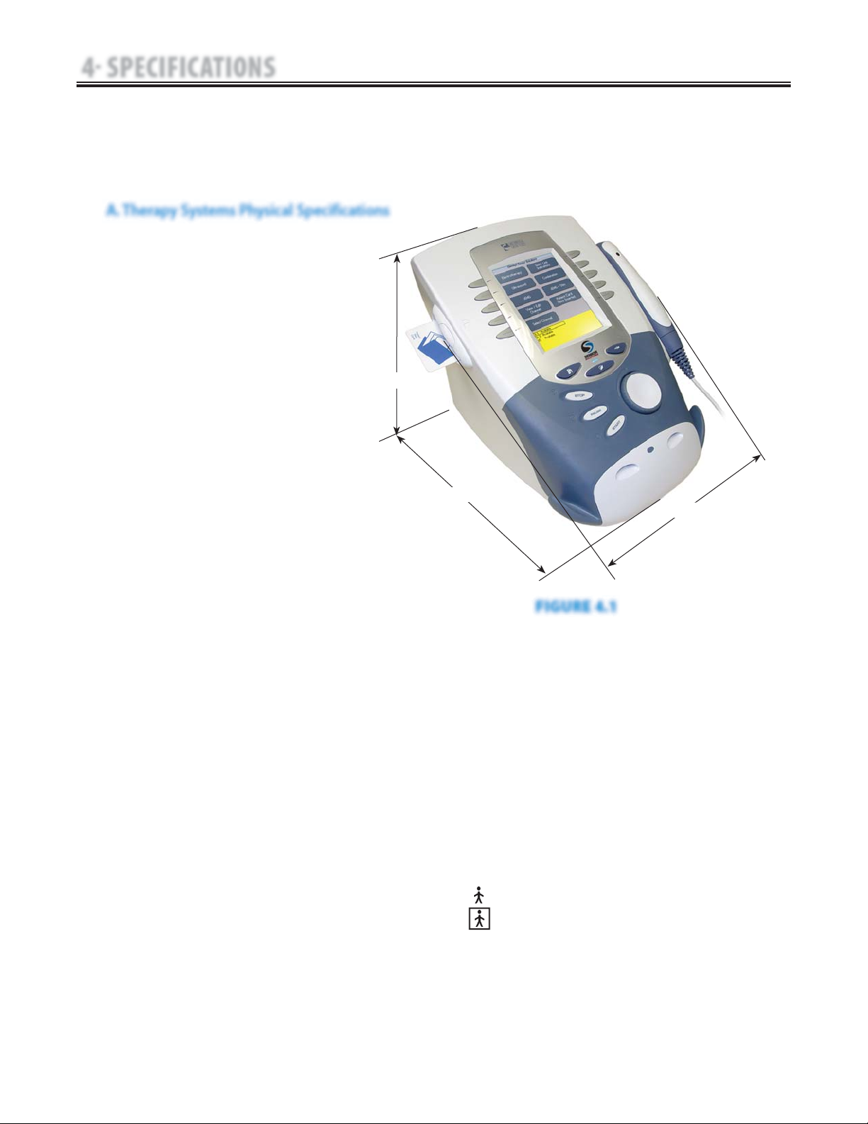
4.1 SENIOR SOLUTIONS THERAPY SYSTEM
A. Therapy Systems Physical Specifications
FIGURE 4.1
DIMENSIONS
Width
Combination Unit . . . . . . . . . . . . . . . . . . . . . . 11.375 in (28.9 cm)
Electrotherapy Unit . . . . . . . . . . . . . . . . . . . . . . 9.750 in (24.8 cm)
Depth
(Combination and Electrotherapy Unit) . . 12.750 in (32.4 cm)
Height
(Combination and Electrotherapy Unit) . 8.750 in (22.2 cm)
Standard Weight
Two Channel Combination Unit . . . . . . . . . . . . . . . 7 lbs (3.2 kg)
Two Channel Electrotherapy Unit . . . . . . . . . . . . . 6 lbs (2.7 kg)
Power (Combination and Electrotherapy Units)
Input . . . . . . . . . . . . . . . . . . . . . . . . 100 - 240 V, 218.75 VA, 50/60 Hz
Output (Internal Power Supply) . . . . . . . . . . . . . . . . . . +24 V, 7.3 A
Duty Cycle . . . . . . . . . . . . . . . . . . . . . . . . . . . . . . . . . . . . . . . Continuous
Electrical Class . . . . . . . . . . . . . . . . . . . . . . . . . . . . . . . . . . . . . . . CLASS I
Electrical Type
Ultrasound . . . . . . . . . . . . . . . . . . . . . . . . . . . . . . . . . . . . . . . TYPE B
Electrotherapy and sEMG . . . . . . . . . . . . . . . . . . . . . . . . TYPE BF
Regulatory Compliance
UL/IEC/EN 60601-1
IEC/EN 60601-1-2
IEC 60601-2-5
IEC 60601-2-10
Certified to CAN/CSA C22.2 No. 601.1-M90 w/A2.
NOTE:
All waveforms except High
Voltage Pulsed Current (HVPC)
have been designed with a 200
mA current limit. All output
intensities are measured,
specified, and listed to peak, not
peak to peak.
WIDTH
DEPTH
HEIGHT
17
Senior Solutions™ Therapy System
4 SPECIFICATIONS
A. IFC (Interferential) Traditional (4 Pole)-
Figure 4.2
Interferential Current is a medium frequency waveform. Current is
distributed through two channels (four electrodes). The currents
cross each other in the body at the area requiring treatment.
The two currents interfere with each other at this crossing point,
resulting in a modulation of the intensity (the current intensity
increases and decreases at a regular frequency).
Output Mode…………………………………………Electrodes
Output Intensity………………………………………0-100 mA
Carrier Frequency…………………………………2,500-5,000 Hz
Beat Frequency…………………………………………1-200 Hz
Sweep Time………………………………………………15 sec
Sweep Low Beat Frequency……………………………1-199 Hz
Sweep High Beat Frequency……………………………2-200 Hz
Scan Percentage…………………………Static, 10%, 40%, 100%
Mode Selection…………………………………………CC or CV*
Treatment Time……………………………………. . . . . 1-60 Min
Available on Channel………………………… . . 1&2, 3&4 Option
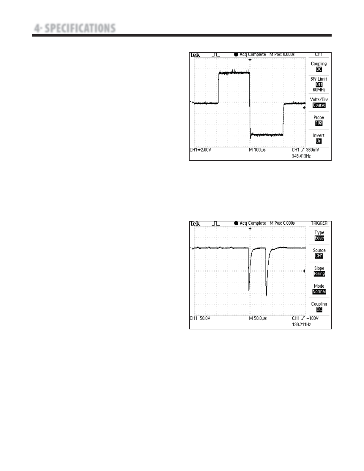
B. TENS- Asymmetrical Biphasic- Figure 4.3
The Asymmetrical Biphasic waveform has a short pulse duration.
It is capable of strong stimulation of the nerve fibers in the skin
as well as of muscle tissue. This waveform is often used in TENS
devices. Because of its short pulse, the patient typically tolerates
the current well, even at relatively high intensities.
Output Mode………………………………………Electrodes
Output Intensity……………………………………0-110 mA
Phase Duration………………………Adjustable 20-1,000 μsec
Frequency……………………………………………1-250 Hz
Mode Selection………………………………………CC or CV*
Burst Frequency………………………………………0-10 bps
Frequency Modulation………………………………0-250 Hz
Amplitude Modulation…………Off, 40%, 60%, 80%, and 100%
Treatment Time………………………………………1-60 min
The specifications found in this section provide
the necessary waveform specifications to aid in
troubleshooting. A waveform graphic from an
oscilloscope is also provided for clarification.
Refer to this section when performing
troubleshooting, replacement, and repair of the
Therapy System, Modules, and Accessories.
NOTE:
All waveforms, except High Voltage Pulsed Current
(HVPC), of the Senior Solutions Therapy System have
a 200 mA current limit.
VMS™, VMS™ Burst, and all TENS waveform output
intensities are measured, specified, and listed to
peak, not peak to peak.
All waveforms are available on all channels.
FIGURE 4.2
Stimulus delivered by the TENS waveforms of this device, in certain
configurations, will deliver a charge of 25 microcoulombs (μC) or
greater per pulse and may be sufficient to cause electrocution.
Electrical current of this magnitude must not flow through the
thorax because it may cause a cardiac arrhythmia.
FIGURE 4.3
*CC= Constant Current
CV= Constant Voltage
4.2 ELECTROTHERAPY WAVEFORM SPECIFICATIONS
18
Senior Solutions™ Therapy System
4 SPECIFICATIONS
C. TENS- Symmetrical Biphasic- Figure 4.4
The Symmetrical Biphasic waveform has a short pulse duration
and is capable of strong stimulation of nerve fibers in the skin
and in muscle. This waveform is often used in portable muscle
stimulation units, and some TENS devices. Because of its short
pulse duration, the patient typically tolerates the current well,
even at relatively high intensities.
Output Mode……………………………Electrodes
Output Intensity……………………………0-80 mA
Phase Duration……………Adjustable 20-1000 μsec
Frequency…………………………………1-250 Hz
Mode Selection…………………………… CC or CV*
Burst Frequency……………………………0-10 bps
Frequency Modulation……………………0-250 Hz
Amplitude ModulationOff, 40%, 60%, 80%, and 100%
Treatment Time……………………………1-60 min
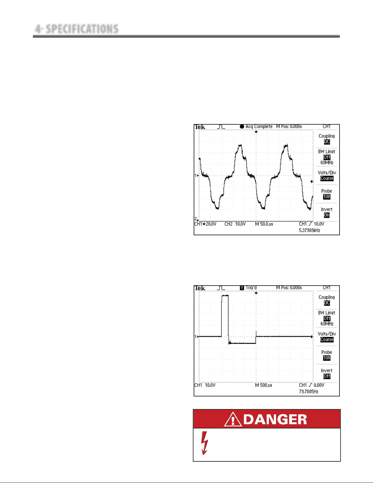
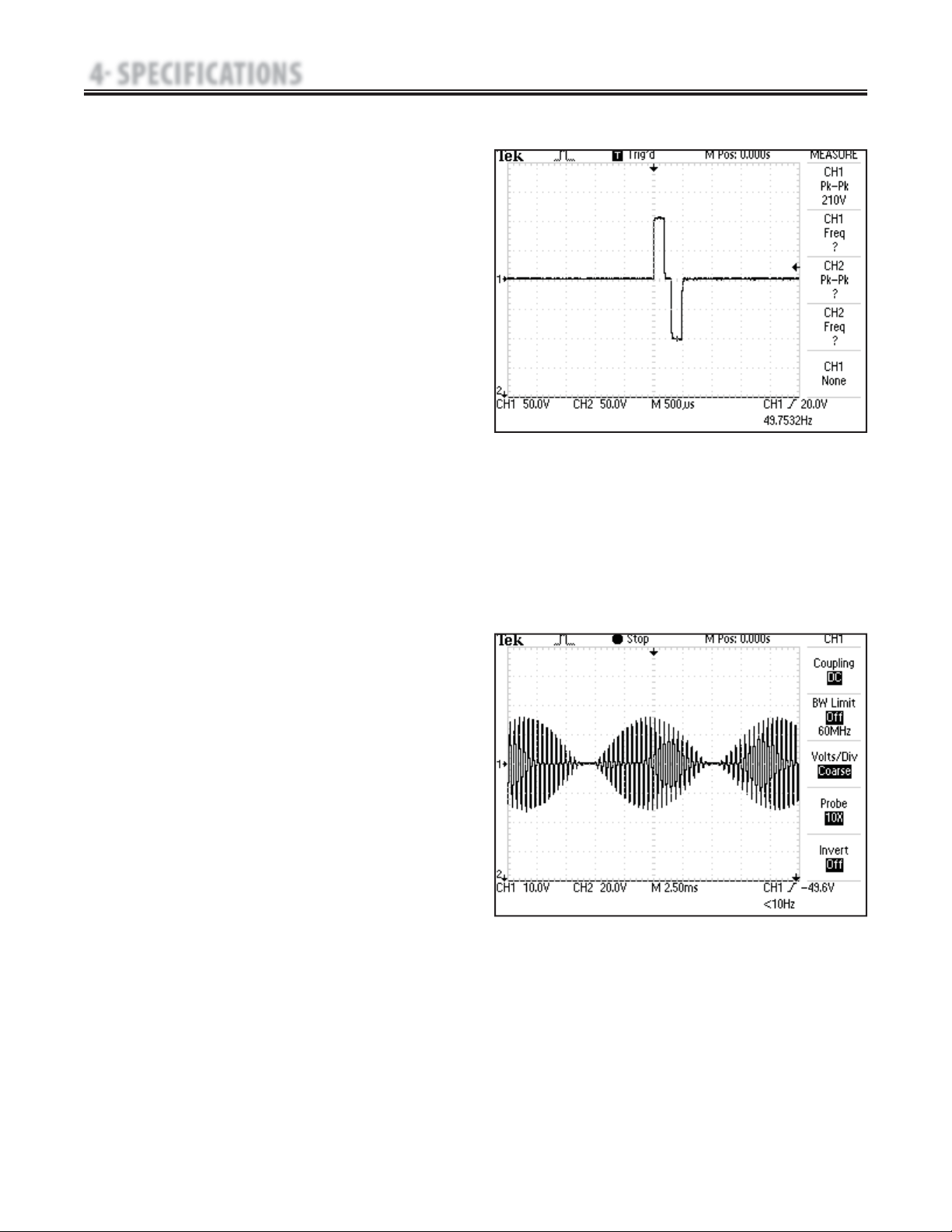
D. High Voltage Pulsed Current (HVPC)-
Figure 4.5
The High Voltage Pulsed Current (HVPC) has a very
brief pulse duration characterized by two distinct peaks
delivered at high voltage. The waveform is monophasic
(current flows in one direction only). The high voltage
causes a decreased skin resistance making the current
comfortable and easy to tolerate.
Output Mode…………………………Electrodes or Probe
Output Intensity……………………………………0-500 V
Polarity……………………………… Positive or Negative
Ramp……………………………0.5 sec, 1 sec, 2 sec, 5 sec
Display………………………………Peak Current or Volts
Sweep…… Continuous, 80/120 pps, 1/120 pps, 1/10 pps
Frequency…………………………………… 10-120 pps
Cycle Time…5/5, 4/12, 10/10, 10/20, 10/30, 10/50, Continuous
Treatment Time………………………………… 1-60 Min
Available on Channels…………………1 & 2, 3 & 4 Option
FIGURE 4.4
FIGURE 4.5
*CC= Constant Current
CV= Constant Voltage
4.2 ELECTROTHERAPY WAVEFORM SPECIFICATIONS (CONTINUED)
19
Senior Solutions™ Therapy System
4 SPECIFICATIONS
E. VMS
™
- Figure 4.6
VMS is a symmetrical biphasic waveform with a 100 μsec interphase
interval. Because the pulse is relatively short, the waveform has a low
skin load, making it suitable for applications requiring high intensities,
such as in muscle strengthening protocols.
Output Mode………………………………………Electrodes
Output Intensity………………………………………0-200 mA
Channel Mode……………………Single, Reciprocal, Co-Contract
Phase Duration………………………………………20-400 μsec
Mode Selection…………………………………………CC or CV*
Anti-Fatigue……………………………………………Off or On
Set Intensity…Individual Channel Intensity Setting in Reciprocal and
…………………………………………………Co-Contract modes
Cycle Time…………Continuous, 5/5, 4/12, 10/10, 10/20, 10/30, 10/50
Frequency…………………………………………………1-200 pps
Ramp………………………………0.5 sec, 1 sec, 2 sec, and 5 sec
Treatment Time…………………………………………1-60 min
Available on Channels.……………………… 1 & 2, 3 & 4 Option
F. IFC (Interferential) Premodulated (2p)- Figure
4.7
Premodulated Current is a medium frequency waveform.
Current comes out of one channel (two electrodes). The
current intensity is modulated: it increases and decreases
at a regular frequency (the Amplitude Modulation
Frequency).
Output Mode……………………………………Electrodes
Output Intensity……………………………………0-100 mA
Carrier Frequency…………………………………2,500 Hz
Beat Fixed (Sweep Off)……………………………1-200 Hz
Sweep Low Beat Frequency………………………1-199 Hz
Sweep High Beat Frequency…………………… 2-200 Hz
Cycle Time…Continuous, 5/5, 4/12, 10/10, 10/20, 10/30, 10/50
Mode Selection ……………………………………CC or CV*
Treatment Time………………………………… 1-60 Min
Available on Channel………………… 1 & 2, 3 & 4 Option
FIGURE 4.6
*CC= Constant Current
CV= Constant Voltage
4.2 ELECTROTHERAPY WAVEFORM SPECIFICATIONS (CONTINUED)
FIGURE 4.7
20
Senior Solutions™ Therapy System
4 SPECIFICATIONS
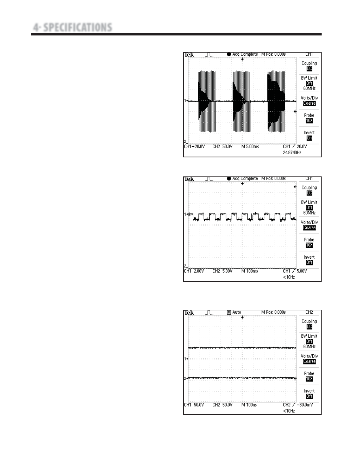
G. Russian- Figure 4.8
Russian Current is a sinusoidal waveform, delivered in
bursts or series of pulses. This method was claimed by its
author (Kots) to produce maximal muscle strengthening
effects without significant discomfort to the patient.
Output Mode…………………………………Electrodes
Output Intensity…………………………………0-100 mA
Channel Mode…………… Single, Reciprocal, Co-Contract
Duty Cycle……………………10%, 20%, 30%, 40%, 50%
Mode Selection………………………………… CC or CV*
Anti-Fatigue………………………………………Off or On
Cycle Time…5/5, 4/12, 10/10, 10/20, 10/30, 10/50, Continuous
Burst Frequency (Anti-Fatigue Off )……………20-100 bps
Ramp………………………0.5 sec, 1 sec, 2 sec, and 5 sec
Treatment Time…………………………………1-60 min
Available on Channels……………… 1 & 2, 3 & 4 Option
H. Microcurrent- Figure 4.9
Microcurrent is a monophasic waveform of very low
intensity that closely simulates the electrical current
generated by the human body. Microcurrent can be
applied via electrodes or probe.
Output Mode…………………………Electrodes or Probe
Output Intensity……………………………………0-1000 μA
Polarity………………… Positive, Negative or Alternating
Treatment Time………………………………… 1-60 Min
Available on channels…………………1 & 2, 3 & 4 Option
I. DC (Direct Current)- Figure 4.10
DC Current is a direct current flowing in one direction only.
The current can be continuous or interrupted.
Output Mode……………………………………Electrodes
Output Intensity……………………………………0-4 mA
Polarity Reversal…………………………………On or Off
With Polarity Reversal On, Polarity will change at
50% of treatment time.
Cycle Time………………………… Continuous, 5/60, 10/60
Treatment Time…………………………………1-10 min
Available on Channels…………………1 & 2, 3 & 4 Option
*CC= Constant Current
CV= Constant Voltage
FIGURE 4.8
FIGURE 4.9
4.2 ELECTROTHERAPY WAVEFORM SPECIFICATIONS (CONTINUED)
FIGURE 4.10
21
Senior Solutions™ Therapy System
4 SPECIFICATIONS
*CC= Constant Current
CV= Constant Voltage
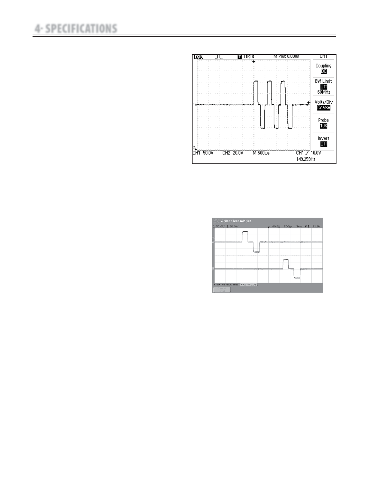
FIGURE 4.11
J. VMS
™
Burst- Figure 4.11
VMS Burst is a symmetrical biphasic waveform delivered in a burst
format. Because the pulse is relatively short, the waveform has a low
skin load, making it suitable for applications requiring high intensities,
such as in muscle strengthening protocols.
Output Mode……………………………………Electrodes
Output Intensity……………………………………0-200 mA
Channel Mode………………Single, Reciprocal, Co-Contract
Phase Duration…………………………………20-400 μsec
Mode Selection…………………………………… CC or CV*
Anti-Fatigue…………………………………………Off or On
Set Intensity…………Individual Channel Intensity Setting in
…………………………Reciprocal and Co-Contract modes
Cycle Time…Continuous, 5/5, 4/12, 10/10, 10/20, 10/30, 10/50
Frequency…………………………………………1-200 pps
Ramp…………………………… 0.5 sec, 1 sec, 2 sec, 5 sec
Treatment Time………………………………… 1-60 min
Available on Channels……………1 & 2, 3 & 4 Option
4.2 ELECTROTHERAPY WAVEFORM SPECIFICATIONS (CONTINUED)
VMS FR is a version of the existing VMS waveform that incorporates
channel interaction and amplitude modulation to stimulate the
movement and coordination of an agonist/antagonist muscle group.
Because the pulse is relatively short, the waveform has a low skin load,
making it suitable for applications requiring high intensities, such as in
muscle strengthening protocols.
Output Mode . . . . . . . . . . . . . . . . . . . . . . . . . . . . . . . . . . . . . . . . . . . . . . . . . Electrodes
Output Intensity . . . . . . . . . . . . . . . . . . . . . . . . . . . . . . . . . . . . . . . . . . . . . . . . . . . . . . . .0-150 mA
Phase Duration . . . . . . . . . . . . . . . . . . . . . . . . . . . . . . . . . . . . . . . . . . . . . . . . . . . . . . 20-400 μsec
Burst Duration . . . . . . . . . . . . . . . . . . . . . . . . . . . . . . . . . . . . . . . . . . . . . . . . . . . . . . 200-5000 ms
On/Off Ratio . . . . . . . . . . . . . . . . . . . . . . . . . . . . . . . . . . . . . . . . . . . . . . . . . . . . . .1:3, 1:4, and 1:5
Mode Selection . . . . . . . . . . . . . . . . . . . . . . . . . . . . . . . . . . . . . . . . . . . . . . . . . . . . . . . CC or CV*
Set Intensity . . . . . . . . . . . . . . . . . . . . . . . . . . Channel 1, Channel 2, and Both Channels
Frequency . . . . . . . . . . . . . . . . . . . . . . . . . . . . . . . . . . . . . . . . . . . . . . . . . . . . . . . . . . . . . 20-80 pps
Treatment Time . . . . . . . . . . . . . . . . . . . . . . . . . . . . . . . . . . . . . . . . . . . . . . . . .1-60 min
Available on Channels . . . . . . . . . . . . . . . . . . . . . . . . . . . . . . . .1 & 2, 3 & 4 Option
K. VMS™
FR - Figure 4.12
FIGURE 4.12
22
Senior Solutions™ Therapy System
4 SPECIFICATIONS
Ultrasound
Frequency . . . . . . . . . . . . . . . . . . . . . . . . . . . . . . . . . . . . . . . . . . . . . . . . . . . . . . . . . . . . . . . . . . . . . . . . . . . . . . . . . . . . . . . . . . . . . . . 1 MHz, ± 5%; 3.3 MHz, ±5%
Duty Cycles . . . . . . . . . . . . . . . . . . . . . . . . . . . . . . . . . . . . . . . . . . . . . . . . . . . . . . . . . . . . . . . . . . . . . . . . . . . . . . . . . . . . . . . . . 10%, 20%, 50%, and Continuous
Pulse Frequency . . . . . . . . . . . . . . . . . . . . . . . . . . . . . . . . . . . . . . . . . . . . . . . . . . . . . . . . . . . . . . . . . . . . . . . . . . . . . . . . . . . . . . . . . . . . . . . . . . . . . . . . . . . . . .100 Hz
Pulse Duration . . . . . . . . . . . . . . . . . . . . . . . . . . . . . . . . . . . . . . . . . . . . . . . . . . . . . . . . . . . . . . . . . . . . .1 mSec, ±20%; 2 mSec, ±20%, and 5 mSec, ±20%
Output Power
10 cm
2
Crystal . . . . . . . . . . . . . . . . . . . . . . . . . . . . . . . . . . . . . . . . . . . . . . . . . . . . . . . . . . . . . . . . . . . . . . . 0-20 Watts at 1 MHz and 0-10 Watts at 3.3 MHz
5 cm
2
Crystal . . . . . . . . . . . . . . . . . . . . . . . . . . . . . . . . . . . . . . . . . . . . . . . . . . . . . . . . . . . . . . . . . . . . . . . . . . . . . . . . . . . . . . . . . . . . . 0-10 Watts, 1 and 3.3 MHz
2 cm
2
Crystal . . . . . . . . . . . . . . . . . . . . . . . . . . . . . . . . . . . . . . . . . . . . . . . . . . . . . . . . . . . . . . . . . . . . . . . . . . . . . . . . . . . . . . . . . . . . . . .0-4 Watts, 1 and 3.3 MHz
1 cm
2
Crystal . . . . . . . . . . . . . . . . . . . . . . . . . . . . . . . . . . . . . . . . . . . . . . . . . . . . . . . . . . . . . . . . . . . . . . . . . . . . . . . . . . . . . . . . . . . . . . . . 0-2 Watts 3.3 MHz Only
Amplitude . . . . . . . . . . . . . . . . . . . . . . . . . . . . . . . . . . . . . . . . . . . . . . . . . . . . . . . . . . . . . . . . . . . . . . . . . . . . . . . . . . . . . . 0 to 2.5
W/cm
2
in continuous mode,
0-3 W/cm
2
in pulsed modes
Output accuracy . . . . . . . . . . . . . . . . . . . . . . . . . . . . . . . . . . . . . . . . . . . . . . . . . . . . . . . . . . . . . . . . . . . . . . . . . . . . . . . . . . . . . ± 20% above 10% of maximum
Temporal Peak to Average Ratios. . . . . . . . . . . . . . . . . . . . . . . . . . . . . . . . . . . . . . . . . . . . . . . . . . . . . . . . . . . . . . . . . . . . . . . 2:1, ± 20%, at 50% Duty Cycle
5:1, ± 20%, at 20% Duty Cycle
9:1, ± 20%, at 10% Duty Cycle
Beam Nonuniformity Ratio. . . . . . . . . . . . . . . . . . . . . . . . . . . . . . . . . . . . . . . . . . . . . . . . . . . . . . . . . . . . . . . . . . . . . . . . . . . . . . . . . . . . . . . . .5.0 : 1 maximum
Beam Type . . . . . . . . . . . . . . . . . . . . . . . . . . . . . . . . . . . . . . . . . . . . . . . . . . . . . . . . . . . . . . . . . . . . . . . . . . . . . . . . . . . . . . . . . . . . . . . . . . . . . . . . . . . . . . . Collimating
Effective Radiating Areas . . . . . . . . . . . . . . . . . . . . . . . . . . . . . . . . . . . . . . . . . . . . . . . . . . . . . . . . . . . . . . . . . . . . . . . . . . . . . . . 10 cm
2
Crystal - 8.5 cm
2
, ±1.5
5 cm
2
Crystal - 4.0 cm
2
, ±1.0
2 cm
2
Crystal - 1.8 cm
2
, +0.2/-0.4
1 cm
2
Crystal - 0.8 cm
2
, +0.2/-0.4
Treatment Time . . . . . . . . . . . . . . . . . . . . . . . . . . . . . . . . . . . . . . . . . . . . . . . . . . . . . . . . . . . . . . . . . . . . . . . . . . . . . . . . . . . . . . . . . . . . . . . . . . . . . . . . . . . . . . . . . . . 1-30 Mins
Head Warming Feature
The Head Warming feature of the Senior Solutions Combination Therapy System utilizes ultrasound output resulting in warming of the
Sound Head to increase patient comfort.
With Head Warming enabled, ultrasound is emitted without pressing the START button. The Applicator LED will not illuminate during the
Head Warming period. US Channel will indicate "Head Warming".
Output . . . . . . . . . . . . . . . . . . . . . . . . . . . . . . . . . . . . . . . . . . . . . . . . . . . . . . . . . . . . . . . . . . . . . . . . . . . . . . . . . . . . . . . . . . . . . . . . . 0 - 50% Cycling of maximum power
Frequency . . . . . . . . . . . . . . . . . . . . . . . . . . . . . . . . . . . . . . . . . . . . . . . . . . . . . . . . . . . . . . . . . . . . . . . . . . . . . . . . . . . . . . . . . . . . . . . . . . . . . . . . . . . . . . . . . . . . . . . . . . . 3.3 Mhz
Sound Head Temperature . . . . . . . . . . . . . . . . . . . . . . . . . . . . . . . . . . . . . . . . . . . . . . . . . . . . . . . . . . . . . . . . . . . . . . . . . . . . . . . . . . . 85 °F - 110 °F (29.4 °C - 43.3 °C)
This section provides the necessary Ultrasound
Specifications to aid in troubleshooting the Senior
Solutions Therapy System Ultrasound PC Board and
Applicators.
Refer to these specifications as necessary when
troubleshooting the Ultrasound PC Board and
Applicators.
4.3 ULTRASOUND SPECIFICATIONS
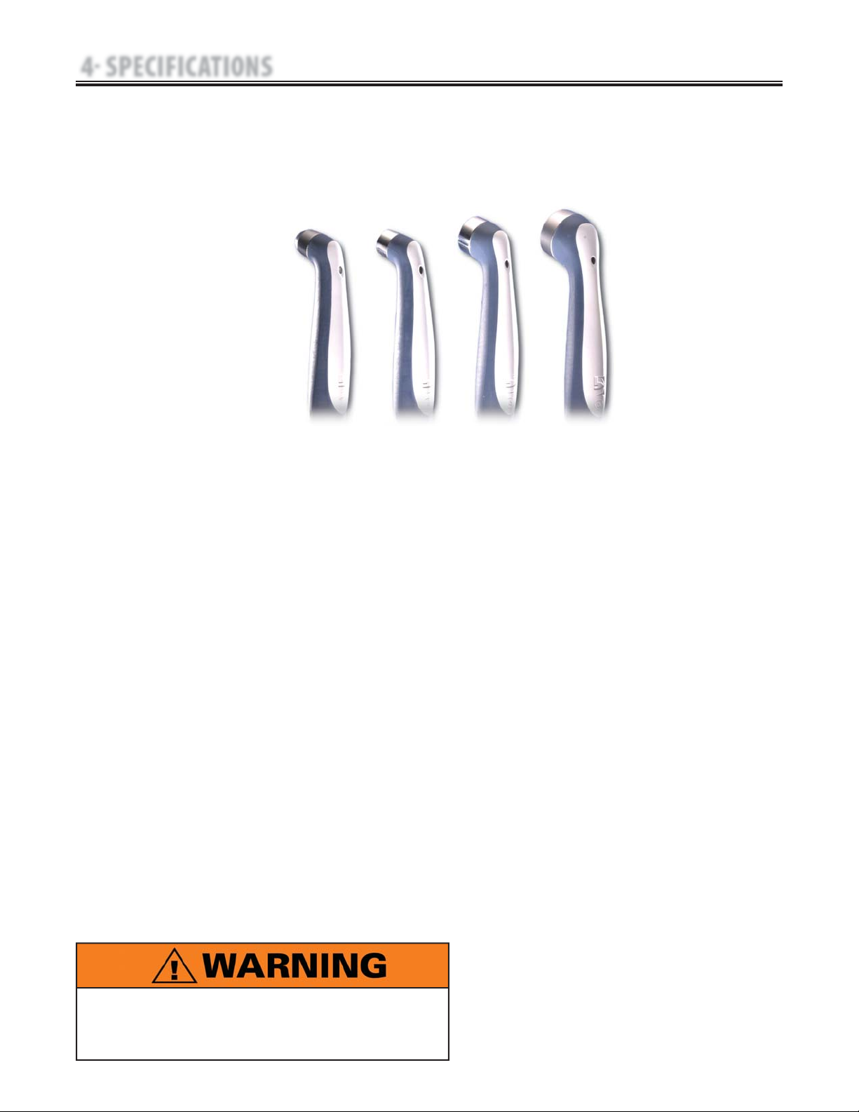
1 cm
2
2 cm
2
5 cm
2
STANDARD
10 cm
2
Do not apply the Ultrasound Applicator to the patient
during the Head Warming period. Applicator must
remain in Applicator Hook during the Head Warming
period.
23
Senior Solutions™ Therapy System
5 TROUBLESHOOTING
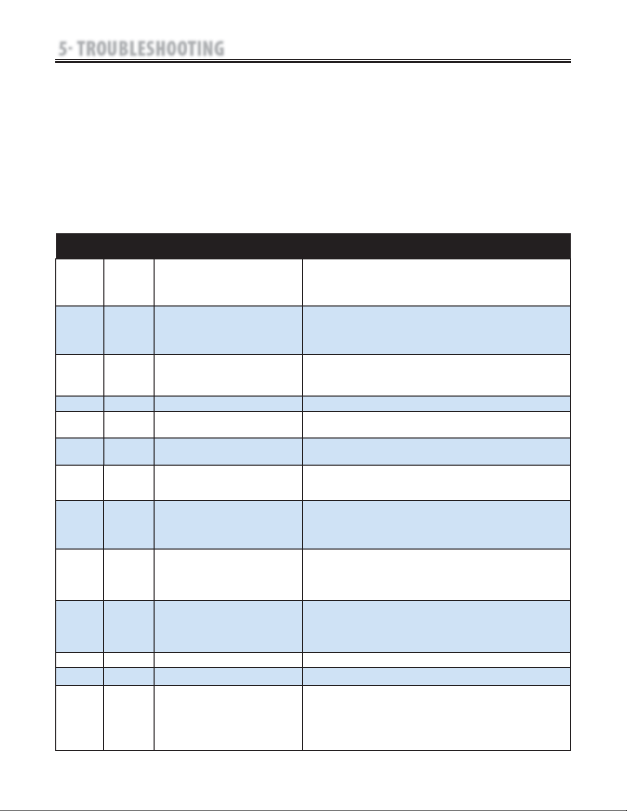
5.1 THERAPY SYSTEM ERROR MESSAGES
A. The information provided below is intended to
aid in defining the Software Error Messages of the
Senior Solutions Therapy System. Once a particular
Error Message is defined the information will also
list probable causes and possible remedies.
No board level troubleshooting or field epair
information is or will be provided by Chattanooga
Group for field repair of the Senior Solutions
Therapy System, Modules, or Accessories.
Error messages in the range of 100 to 199 are
primarily user definable and remedied by following
the instructions given by the Therapy System. Error
messages in the ranges of 200- 299 and 300-399,
require Technical Assistance.
Code
Number
Type
Message
Probable Cause Possible Remedies
100 Warning Overcurrent A. Check Electrodes and Lead Wires. Make certain Lead Wires are not damaged and are properly
connected to the system. Make certain Lead Wires are properly connected to the Electrodes and
that electrodes are not damaged and are making proper contact with treatment area.
B. Replace Lead Wires and Electrodes.
101 Warning Shorted Lead Wires A. Check Electrodes and Lead Wires. Make certain Lead Wires are not damaged and are properly
connected to the system. Make certain Lead Wires are properly connected to the Electrodes and
that electrodes are not damaged and are making proper contact with treatment area.
B. Replace Lead Wires and Electrodes
102 Warning Bad Contact Quality A. Make certain Electrodes are making proper contact with the treatment area.
B. Make certain Lead Wires are properly connected to Electrodes.
C. Replace Electrodes and Lead Wires..
103 Warning Blank Patient ID Properly enter Patient ID. Refer to User Manual for Patient Data Card instructions.
104 Warning 1. Blank Protocol Name
2. Blank Sequence Name
Properly enter Protocol or Sequence Name. Refer to the appropriate section of the
User Manual.
106
107
Warning
Warning
1. Attempting to delete factory set Sequence.
2. Attempting to delete Clinical Protocol.
Cannot delete factory set Clinical Protocols or factory set Sequences.
108 Warning Attempting to save additional User Protocols or
Sequences after system memory has reached the
maximum allowed (200).
Delete some User Protocols or Sequences. Refer to appropriate section of the User Manual for
instructions.
109
110
111
Warning
Warning
Warning
Attempting to access protocols or sequences and
none are found in the system.
A. User Protocols- No protocols have been saved in the system. Refer to Therapy System User
Manual to save User Protocols
B. Sequences- No User Sequences have been saved in the system. Refer to Therapy System User
Manual to save Sequences.
112 Warning Ultrasound Applicator disconnected from system
during treatment session.
A. Connect Ultrasound Applicator to system.
B. If Ultrasound Applicator is connected, reset system by turning power switch Off and On.
C. If problem persists, connect a known good Ultrasound Applicator. If problem continues, contact
dealer or factory for service.
113 Warning Attempting to perform Ultrasound treatment with no
Applicator connected to the system.
A. Connect the desired Ultrasound Applicator to the system.
B. If Ultrasound Applicator is connected, reset system by turning power switch Off and On.
C. If problem persists, connect a known good Ultrasound Applicator. If problem continues, contact
dealer or factory for service.
114 Warning Ultrasound Applicator is not calibrated. Use a known good Applicator. If problem continues, contact dealer or factory for service.
115 Warning Ultrasound Applicator is too hot. Allow Ultrasound Applicator Sound Head to cool to ambient temperature.
116
117
Warning
Warning
1. No Patient Data Card is inserted into the system.
2. Attempted to use an Invalid Patient Data Card.
A. Properly insert the Patient Data Card into the system port. Refer to Therapy System User Manual
for new and existing Patient Data Card instructions.
B. Use a known good Patient Data Card.
C. Make certain a Patient Data Card and not an sEMG Data Card is being used.
D. If problem continues, contact dealer or factory for service.
24
Senior Solutions™ Therapy System
5 TROUBLESHOOTING
129 Warning sEMG Data Card full. sEMG Data Card faulty. Inser t a known good sEMG Data Card. If problem continues,
contact dealer or factory for service.
135 Warning Control Board Software upgrade warning. Upgrade Control Board Software to latest version. Contact dealer or Chattanooga Group for
latest software upgrade and instructions.
136 Warning Stim Board Main Software upgrade warning. Upgrade Stim Board Software to latest version. Contact dealer or Chattanooga Group for
latest software upgrade and instructions.
137 Warning Stim Board Main Software upgrade warning. Upgrade Stim Board Software to latest version. Contact dealer or Chattanooga Group for
latest software upgrade and instructions.
138 Warning Ultrasound Board Software upgrade warning. Upgrade Ultrasound Board Software to latest version. Contact dealer or Chattanooga Group
for latest software upgrade and instructions.
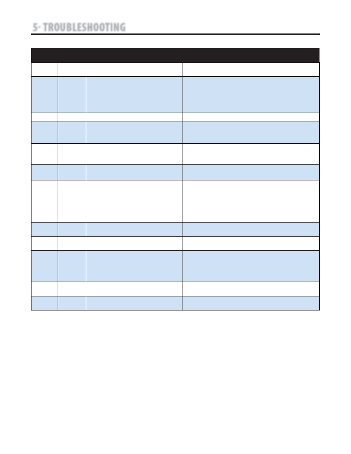
Code
Number
Type
Message
Probable Cause Possible Remedies
118 Warning Attempting to save additional User Protocols or Sequences after
system memory has reached the maximum allowed (200).
Delete some User Protocols or Sequences. Refer to appropriate section of the Therapy
System User Manual for instructions.
119
120
121
122
Warning
Warning
Warning
Warning
1. Attempted to read a treatment from Patient Data Card that is
not a valid treatment for the system.
2. Attempted to use a Non-Patient Data Card.
3. No Patient Data Card inserted into system port.
4. Unknown type of smart card inserted into system.
A. Use a Patient Data Card with proper treatment data for the system.
B. Properly insert a Patient Data Card.
C. Insert a known good Patient Data Card.
D. If problem persists, insert a known good Patient Data Card. If problem continues, contact
dealer or Factory for service.
123 Warning Patient Data Card is full. Erase Patient Data Card. Refer to Therapy System User Manual for instructions.
124 Warning Patient Treatment Data already saved.. A. Cannot save same data again on Patient Data Card.
B. Use a new Patient Data Card to resave data.
C. Erase Patient Data Card and resave treatment data.
125 Warning Multimedia Card (MMC) not in system port. A. Properly insert the MMC card into the system port.
B. Insert a known good MMC Card. If problem continues, contact dealer or Chattanooga
Group for Service.
126 Warning No valid channels are available for attempted treatment. A. Complete existing treatment before attempting to START another.
B. Reset Therapy System by turning main power switch Off and On.
127
128
Warning
Warning
1. No sEMG Channels are available for treatment.
2. No sEMG Module installed or detected by system.
A. Wait until current treatment is complete.
B. Reset Therapy System by turning main power switch Off and On.
C. Make certain sEMG Module is properly installed. Refer to sEMG Module User Manual for
installation instructions.
D. Replace sEMG Module with known good sEMG Module.
E. If problem continues, contact dealer or factory for service.
5.1 THERAPY SYSTEM ERROR MESSAGES (CONTINUED)
25
Senior Solutions™ Therapy System
5 TROUBLESHOOTING
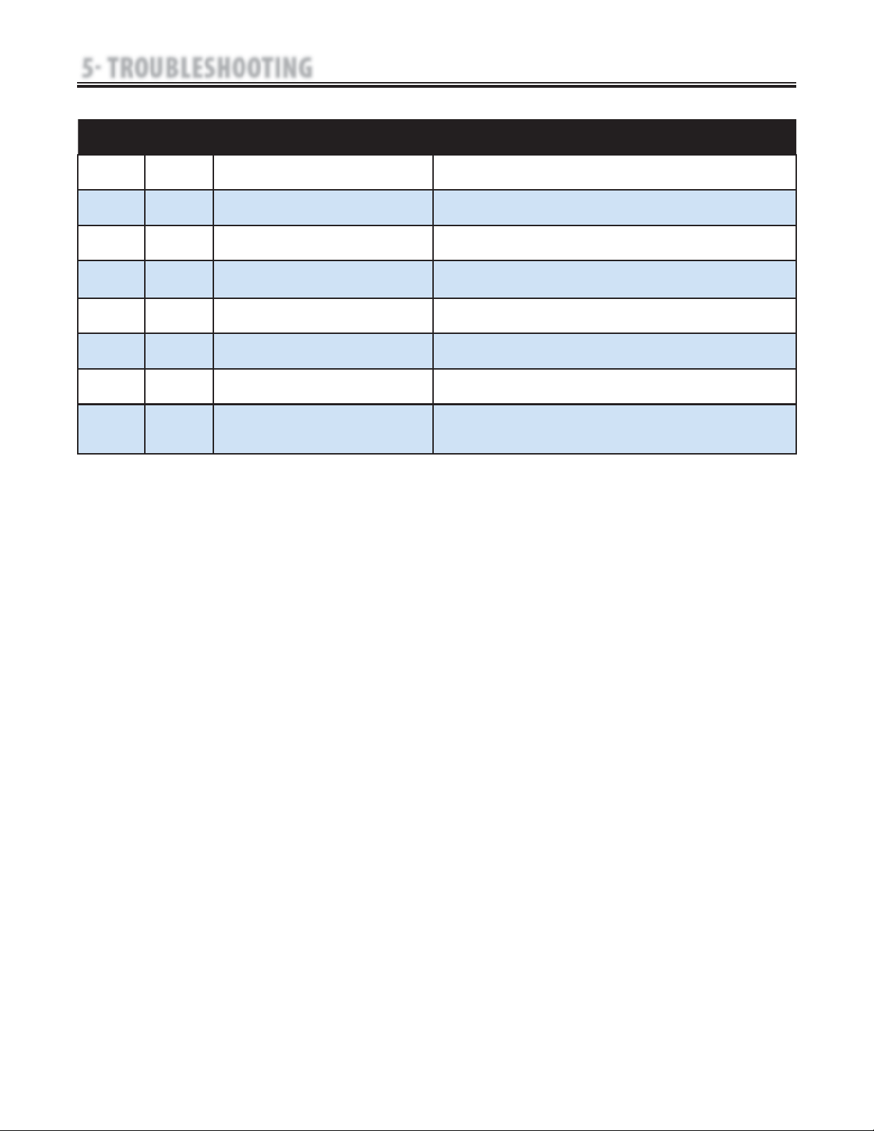
Code
Number
Type
Message
Probable Cause Possible Remedies
135 Warning Control Board Software upgrade warning. Upgrade Control Board Software to latest version. Contact dealer or Chattanooga Group for latest
software upgrade and instructions.
136 Warning Stim Board Main Software upgrade warning. Upgrade Stim Board Software to latest version. Contact dealer or Chattanooga Group for latest
software upgrade and instructions.
137 Warning Stim Board Main Software upgrade warning. Upgrade Stim Board Software to latest version. Contact dealer or Chattanooga Group for latest
software upgrade and instructions.
138 Warning Ultrasound Board Software upgrade warning. Upgrade Ultrasound Board Software to latest version. Contact dealer or Chattanooga Group for
latest software upgrade and instructions.
140 Warning MMC Software upgrade warning. Upgrade MMC Software to latest version. Contact dealer or Chattanooga Group for latest software
upgrade and instructions.
141 Warning Battery Module Software upgrade warning. Upgrade Battery Software to latest version. Contact dealer or Chattanooga Group for latest
software upgrade and instructions.
142 Warning A Laser Protocol was selected but no Laser Module is
installed on system.
Install Laser Module to Therapy System. Refer to Laser Module User Manual for installation
instructions.
145 Warning Patient Data Card Button on Home Screen was pressed
with no Patient Data Card installed into system port and
no treatment currently being performed.
Properly insert a Patient Data Card, set up and perform the treatment and save data to Patient
Data Card.
5.1 THERAPY SYSTEM ERROR MESSAGES (CONTINUED)
 Loading...