

Page 1

Installation/Operation Manual with Service Replacement Parts
2
E
series High Temperature
Upright Conveyor Dishwasher
EEUCCW-8
EEUCCW-6
EEUCCW-4
Models:
EEUCCW
29" wide conveyor with a 4', 6',or 8' center section
Dishwasher Serial No.
114593_B
P.O. Box 4149
Winston-Salem, NC 27115
336/661-1556 Fax: 336/661-1660
www.championindustries.com
2674 N. Service Road,
Jordan Station Ontario, Canada L0R 1S0
905/562-4195 Fax: 905/562-4618
Issue Date: 12.6.09
Manual P/N
Printed in the USA
114593 rev.B
Page 2
For future reference, record your dishwasher information in the box below.
Model Number__________________________ Serial Number_______________________
Voltage________________Hertz_____________ Phase__________________
Champion Service Agent __________________________________ Tel:______________________
Champion Parts Distributor _________________________________ Tel:______________________
ATTENTION:
The dishwasher model no., serial no., volt-
age, Hz and phase are needed to identify
your machine and to answer questions.
Please have this information on-hand
if you call for service assistance.
For all models:
The data plate mounts to
one side of the top-mounted
control cabinet.
National Service Department
In Canada: In the USA:
Toll-free: 800/ 263-5798 Toll-free: 800/ 858-4477
Tel: 905/ 562-4195 Tel: 336/ 661-1556
Fax: 905/ 562-4618 Fax: 336/ 661-1660
email: service@moyerdiebellimited.com email: service@championindustries.com
COPYRIGHT © 2009 All rights reserved Printed in the USA
Page 3

CHAMPION-MOYER DIEBEL
ATTENTION:
P0 BOX 301
JORDAN STATION ON LOR 1S0
Complete the back of the POSTAGE PAID WARRANTY CARD below, then cut along
the dashed lines and mail immediately to make sure that your machine warranty is validated.
USE CANADIAN WARRANTY CARD IN CANADA AND USA WARRANTY CARD IN THE UNITED STATES.
NO POSTAGE
NECESSARY
IF MAILED
IN THE
UNITED STATES
BUSINESS REPLY MAIL
FIRST-CLASS MAIL PERMIT NO. 2101 WINSTON-SALEM, NC
POSTAGE WILL BE PAID BY ADDRESSEE
CHAMPION INDUSTRIES INC
PO BOX 4149
WINSTON-SALEM, NC 27119-0981
Page 4

IMPORTANT IMPORTANT
Model
Serial #
Date of Installation:
Company Name:
Telephone #: ( ) ---
Contact:
Address:
Address:
Telephone #:
Contact:
Installation Company:
(Street) State or Province Zip Code
This Card Must Be Returned to Validate Machine Warranty:
WARRANTY REGISTRATION CARD
IMPORTANT IMPORTANT
Model
Serial #
Date of Installation:
Company Name:
Telephone #: ( ) ---
Contact:
Address:
Address:
Telephone #:
Contact:
Installation Company:
(Street) State or Province Zip Code
This Card Must Be Returned to Validate Machine Warranty:
WARRANTY REGISTRATION CARD
Page 5

Revision History
Revision History
The Revision History can contain part number changes, new instructions, or information
that was not available at print time.
• We reserve the right to make changes to these instructions without notice and
without incurring any liability by making the changes..
• Equipment owners may request a revised manual, at no charge, by calling
1 (800) 858-4477 in the USA or by calling 1 (800) 263-5798 in Canada.
Revision Revised Serial Number Revision
Date Pages Effectivity Description
8/6/09 All J09062644 Released rst edition
10/6/09 128-129 J09062644 Revised clutch P/N's
12/6/09 62-71 J09062644 Added standpipe gaskets
i
Page 6

Limited Warranty
LIMITED WARRANTY
Champion Industries Inc. (herein referred to as Champion), P.O. Box 4149, Winston-Salem, North Carolina 27115,
and P.O. Box 301, 2674 N. Service Road, Jordan Station, Canada, L0R 1S0, warrants machines, and parts,
as set out below.
Warranty of Machines: Champion warrants all new machines of its manufacture bearing the name
"Champion" and installed within the United States and Canada to be free from defects in material and workman
ship for a period of one (1) year after the date of installation or fteen (15) months after the date of shipment by
Champion, whichever occurs rst. [See below for special provisions relating to glasswashers.] The warranty
registration card must be returned to Champion within ten (10) days after installation. If warranty card is not
returned to Champion within such period, the warranty will expire after one year from the date of shipment.
Champion will not assume any responsibility for extra costs for installation in any area where there are
jurisdictional problems with local trades or unions.
If a defect in workmanship or material is found to exist within the warranty period, Champion, at its election,
will either repair or replace the defective machine or accept return of the machine for full credit; provided;
however, as to glasswashers, Champion's obligation with respect to labor associated with any repairs shall end
(a) 120 days after shipment, or (b) 90 days after installation, whichever occurs rst. In the event that Champion
elects to repair, the labor and work to be performed in connection with the warranty shall be done during regular
working hours by a Champion authorized service technician. Defective parts become the property of Champion.
Use of replacement parts not authorized by Champion will relieve Champion of all further liability in connection
with its warranty. In no event will Champion's warranty obligation exceed Champion's charge for the machine.
The following are not covered by Champion's warranty:
a. Lighting of gas pilots or burners.
b. Cleaning of gas lines.
c. Replacement of fuses or resetting of overload breakers.
d. Adjustment of thermostats.
e. Adjustment of clutches.
f. Opening or closing of utility supply valves or switching of electrical supply current.
g. Cleaning of valves, strainers, screens, nozzles, or spray pipes.
h. Performance of regular maintenance and cleaning as outlined in operator’s guide.
i. Damages resulting from water conditions, accidents, alterations, improper use, abuse,
tampering, improper installation, or failure to follow maintenance and operation procedures.
j. Wear on Pulper cutter blocks, pulse vanes, and auger brush.
Examples of the defects not covered by warranty include, but are not limited to: (1) Damage to the exterior or
interior nish as a result of the above, (2) Use with utility service other than that designated on the rating plate,
(3) Improper connection to utility service, (4) Inadequate or excessive water pressure, (5) Corrosion from
chemicals dispensed in excess of recommended concentrations, (6) Failure of electrical components due to
connection of chemical dispensing equipment installed by others, (7) Leaks or damage resulting from such
leaks caused by the installer, including those at machine table connections or by connection of chemical
dispensing equipment installed by others, (8) Failure to comply with local building codes, (9) Damage
caused by labor dispute.
Warranty of Parts: Champion warrants all new machine parts produced or authorized by Champion to be free
from defects in material and workmanship for a period of 90 days from date of invoice. If any defect in
material and workmanship is found to exist within the warranty period Champion will replace the defective
part without charge.
DISCLAIMER OF WARRANTIES AND LIMITATIONS OF LIABILITY. CHAMPION'S WARRANTY IS ONLY TO THE EXTENT REFLECTED ABOVE. CHAMPION MAKES NO OTHER WARRANTIES, EXPRESS OR IMPLIED, INCLUDING,
BUT NOT LIMITED, TO ANY WARRANTY OF MERCHANTABILITY, OR FITNESS OF PURPOSE. CHAMPION SHALL
NOT BE LIABLE FOR INCIDENTAL OR CONSEQUENTIAL DAMAGES. THE REMEDIES SET OUT ABOVE ARE
THE EXCLUSIVE REMEDIES FOR ANY DEFECTS FOUND TO EXIST IN CHAMPION DISHWASHING MACHINES AND
CHAMPION PARTS, AND ALL OTHER REMEDIES ARE EXCLUDED, INCLUDING ANY LIABILITY FOR INCIDENTALS
OR CONSEQUENTIAL DAMAGES.
Champion does not authorize any other person, including persons who deal in Champion Dishwashing machines
to change this warranty or create any other obligation in connection with Champion Dishwashing Machines.
ii
Page 7

Table of Contents
Table of Contents
Upright Conveyor Dishwasher
Revision History........................................................................................................ i
Limited Warranty ...................................................................................................... ii
Model Description ..................................................................................................... iv
Installation .............................................................................................................. 1
Operation .............................................................................................................. 25
Cleaning .............................................................................................................. 41
Troubleshooting ..................................................................................................... 46
Service Replacement Parts ................................................................................... 47
Electrical Schematics............................................................................................. 152
iii
Page 8

Model Description
EEUCCW
Electric high temperature ight-type conveyor dishwasher with built-in electric booster in
40°F/22°C rise or an optional 70°F/39°C rise booster.
Multi-Speed conveyor speed controls and Digital Temperature Display
Steam high temperature ight-type conveyor dishwasher with built-in
steam booster in 40°F/22°C rise or an optional 70°F/39°C rise booster.
Multi-Speed conveyor speed controls and Digital Temperature Display.
The installation, and initial start-up of your dishwasher must be performed by qualied
electricians, plumbers, and authorized service technicians trained in commercial
dishwashers.
Champion provides authorized factory trained service agents to supervise the assembly
and initial start-up of your dishwasher.
Defects and repairs caused by unauthorized installers will not be covered by the
dishwasher warranty.
iv
Page 9
Installation
Installation
Plumbing and Electrical Diagram (P & E)
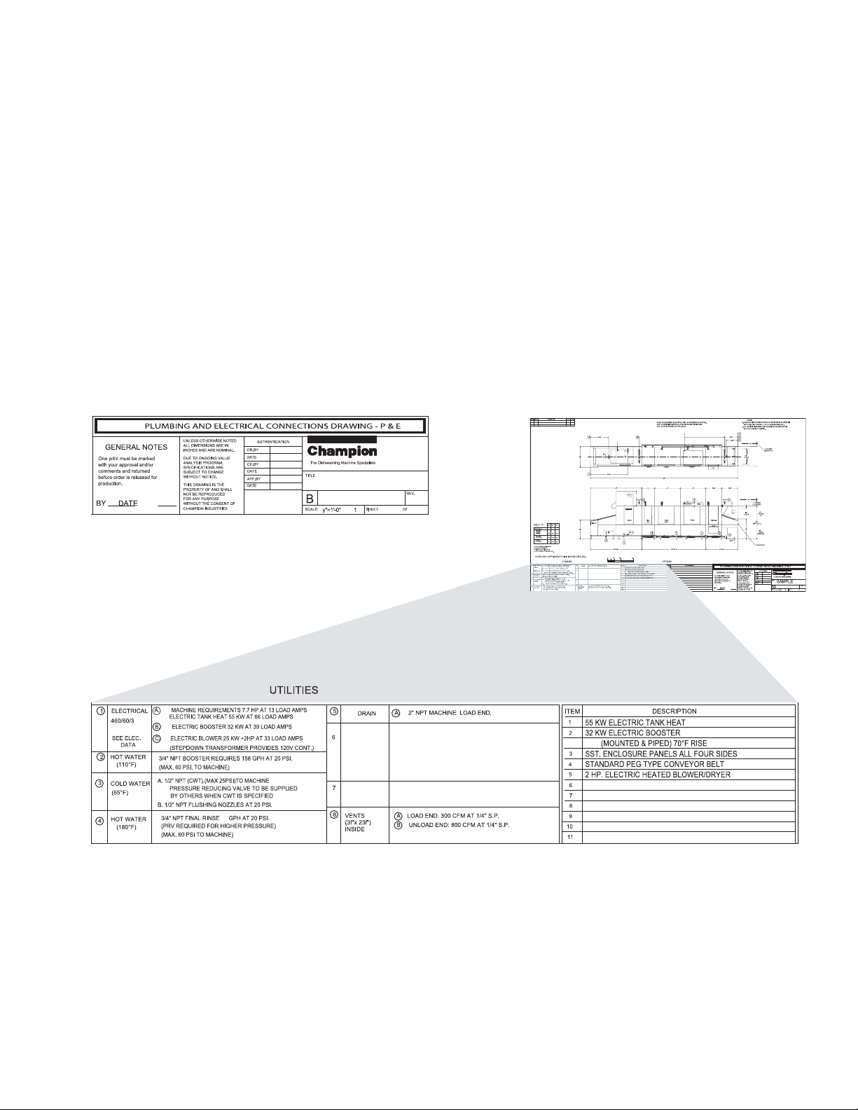
1. A Plumbing and Electrical Diagram, the P&E, was prepared and approved for the installation of the
dishwasher prior to shipment. The P&E contains important information detailing the location and
requirements for the utility connections required for the installation of the dishwasher.
2. The P&E should be used as a guide when inspecting the installation site and in the placement
of the dishwasher sections.
3. A sample P&E is shown below.
SAMPLE
SAMPLE
1
Page 10

Installation
Installation
Dishwasher Construction
Dishwasher Views:
The standard methods for viewing your dishwasher are:
Plan View - Viewed from above
Front view - Viewed facing the top-mounted control cabinet switches.
Side View - Viewed facing the load or unload sections.
1. The minimum distance from wall to dishwasher is 4" [103mm] to allow for utility connections.
2. The room ceiling height must be a minimum of 80" [2032mm] so the doors can be removed
completely.
3. The installation of your dishwasher must be performed by qualied service personnel.
4. Problems due to improper installation are not covered by the Warranty.
5. Compare the utilities at the installation site with the specications listed on each
Plumbing and Electrical Connection Diagram (P&E).
6. The dishwasher data plate is located on the left-hand or right-hand side of the top-mounted
control cabinet.
7. The conveyor direction of travel is referenced from the load section to
the unload section.
If the load section is on your right then direction of travel for the dishwasher is
Right to Left, (R-L).
8. If the load section is on the left then the dishwasher is called a Left to Right, (L-R), dishwasher.
Dishwasher Sections:
1. Load - Soiled ware is sorted and loaded on the conveyor belt.
Wares enter the dishwasher.
2. Prewash Tank - Soiled wares are sprayed to remove large particles and to loosen
heavy food-soils.
3. Wash Tank - Wares are washed with hot water and detergent.
4. Power Rinse Tank - Wares are rinsed with hot water to remove detergent and any
remaining food soils.
5. Auxiliary Rinse - Begins the hot water sanitization process.
6. Final Rinse - Completes the Hot water sanitization process.
7. Unload - Clean wares exit the dishwasher and ash dry on the conveyor belt.
8. Blower Dryer Option - Hot air is forced over wares to speed drying.
9. Heat Recovery Option - Hot air exhaust is recycled to raise the incoming water
temperature for the nal rinse booster reducing energy costs.
2
Page 11
Installation
NOTE:
The installation of your dishwasher must be performed by qualified service personnel.
Problems due to improper installation are not covered by the Warranty.
1. Inspect the outside of the Conveyor pallet for signs of damage.
2. inspect the Conveyor for damage.
3. Check for any accessories that may have shipped with your dishwasher.
4. Turn to the front of this manual and complete the warranty card.
Immediately mail the warranty card to validate your warranty.
5. Move the Conveyor near its permanent location.
CAUTION:
Be careful when lifting and moving the Conveyor to prevent damage to the machine.
Installation
Receiving
NOTE:
The installation of the Conveyor must comply with local safety and health codes.
6. Compare the installation site utility connections with the dishwasher utility connections and
make sure that they are the same.
7. For new dishwasher installations, install the Dishwasher according to the instructions in the
dishwasher service manual Installation, Operation, and Service Replacement Parts, which
is shipped inside the dishwasher.
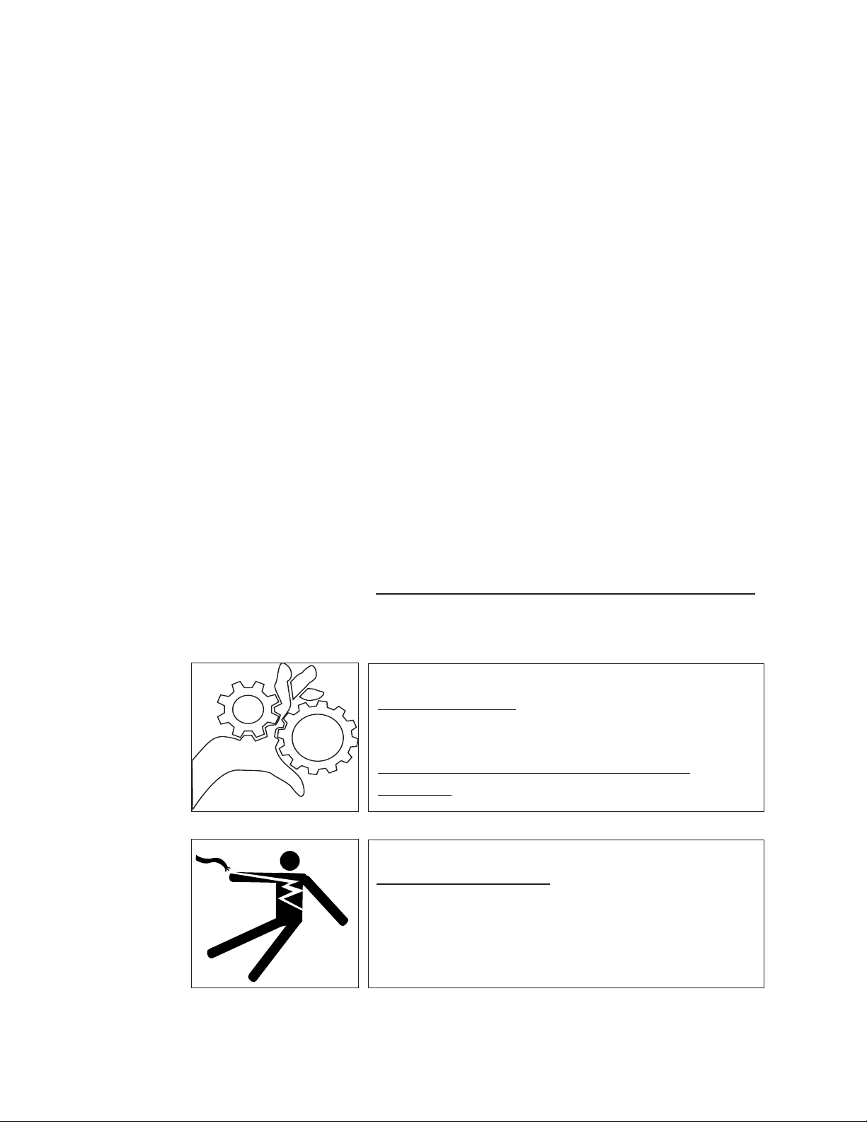
WARNING:
Moving Conveyor Parts may cause INJURY OR DEATH.
Keep hands and clothing clear of the conveyor when the
conveyor is moving.
USE EXTREME CAUTION WHEN THE CONVEYOR
IS MOVING.
WARNING:
Electrocution or serious injury may result when working on an
energized circuit.
Disconnect power at the main breaker or service disconnect
switch before working on the circuit.
Lock-out and tag the breaker to indicate that work is being
performed on the circuit.
3
Page 12
Installation
Installation
Receiving (continued)
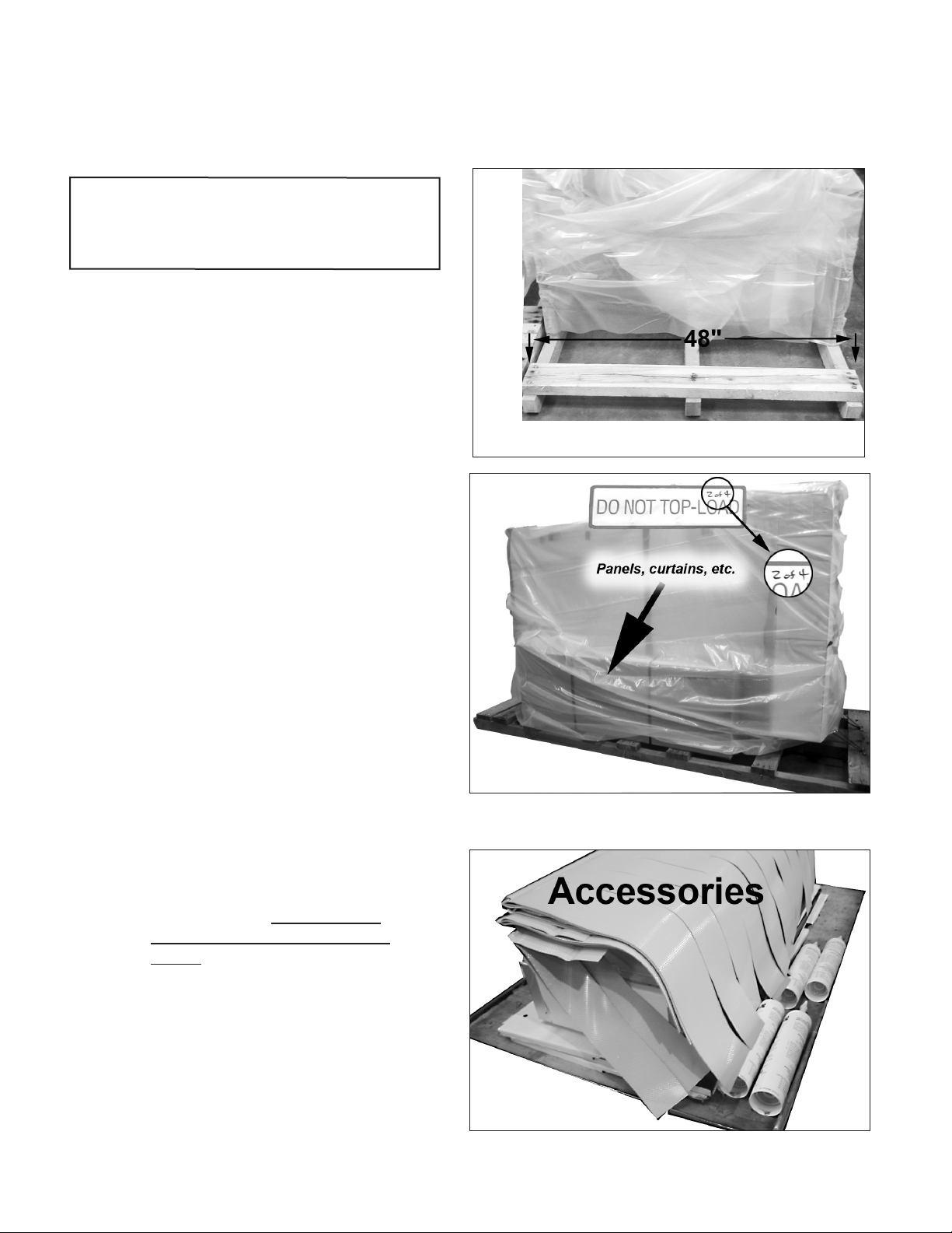
ATTENTION
Shipping pallets measure 48"/122cm
wide. Standard 36"/92cm doorways often
measure less than 35"/89cm in width.
1. Check the shipment for damage
immediately upon receipt.
2. Upright conveyor dishwashers
ship in sections.
3. Each section is wrapped in a
protective covering and secured to
a wooden pallet. Labels note the
total number of sections shipped,
2 of 4, for example.
4. Fasteners, curtains, panels
and other pieces are packed in
cardboard boxes and secured
to the wash/rinse section of the
machine.
5. Inspect the route that the pallets
must travel to the permanent
location.
6. Measure all passageways and
doors before moving the sections
to ensure the route is clear.
7. Piping on the rear wall of the
dishwasher can be removed to
allow the dishwasher to pass
through narrow openings if
necessary.
8. Compare the location of the site
utilities with the Plumbing and
Electrical Connection Diagram,
(P&E).
9. Make sure the utilities match the
dishwasher requirements.
Each section is wrapped and the number of sections is marked
on a label attached to each section.
4
Page 13
CAUTION
Use extreme care when lifting
a section off its pallet to prevent
damage to the dishwasher.
1. Check oor stability. Flooring
must support the weight of the
dishwasher without bowing
when weight is applied.
2. Tiled oors may fracture if loads
are dropped on or drug across
its surface.
3. Move the pallet sections near
their permanent locations.
Remove protective coverings,
shipping straps, brackets and
accessories.
Installation
Installation
Receiving
4. Inspect the underside of each
section, (below the base) and
note the position of piping,
valves, and other components
that may be in the way.
5. Carefully lift each section off
the pallet. Screw the adjustable
bullet-feet in as far as possible,
then lower the section to the
nished oor.
6. The recommended spacing
between sections is 24"/61cm.
5
Page 14
Installation
Installation
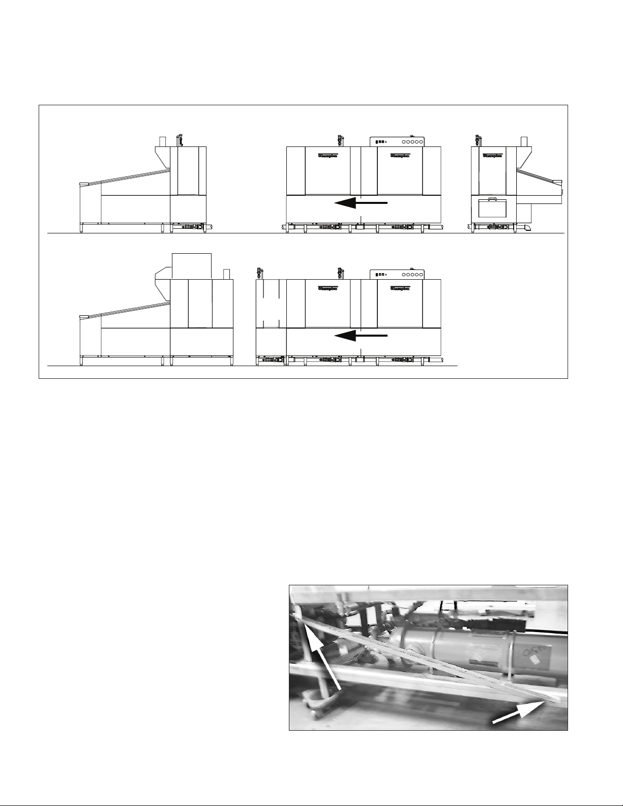
Joining the Sections
B
Unload
B
Unload
C
Wash/Rinse
Quad
Rinse
Blower
Dryer
The dishwasher is shipped in sections and reassembled at the installation site.
Quad
Rinse
Power
Rinse
Direction of Travel
C
Wash/Rinse
Power
Rinse
Direction of Travel
Wash
Wash
A
Load
Pre-
Wash
Right-to-Left
Configuration
Shown
Refer to the illustration above.
The dishwasher is broken into sections for shipping and then reassembled at the installation site. The
main section of the dishwasher is the Wash/Rinse Section (C) which is made up of the wash tank and the
power rinse tank. The Load Section (A) contains the prewash tank and the
Unload Section (B) usually contains the quad rinse tank.
If the dishwasher has an Optional Blower Dryer Section then the quad rinse tank is shipped with the
Wash/Rinse Section (C).
The instructions on the following pages explains how to join the machine sections.
Remove the shipping braces.
6
Page 15
Installation
Installation
Joining the Sections
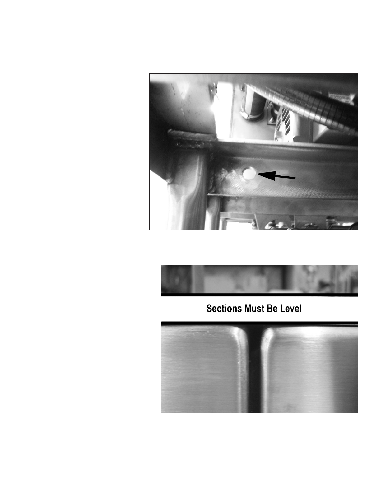
Identify piping..
1. Remove the shipping braces from the sections.
2. Identify the location of piping between the sections.
3. Check the height of each section and determine which
section is the highest due to oor variations.
4. Set the "C" section and adjust to its minimum height.
5. Level the "C" section side to side and front to back in
several places with a bubble level.
6. The remaining sections are leveled in relation to "C"
section.
7. Do not adjust the "C" section too high.
Start leveling the section with the bullet feet
adjusted to a minimum height.
7
Page 16
Installation
Installation
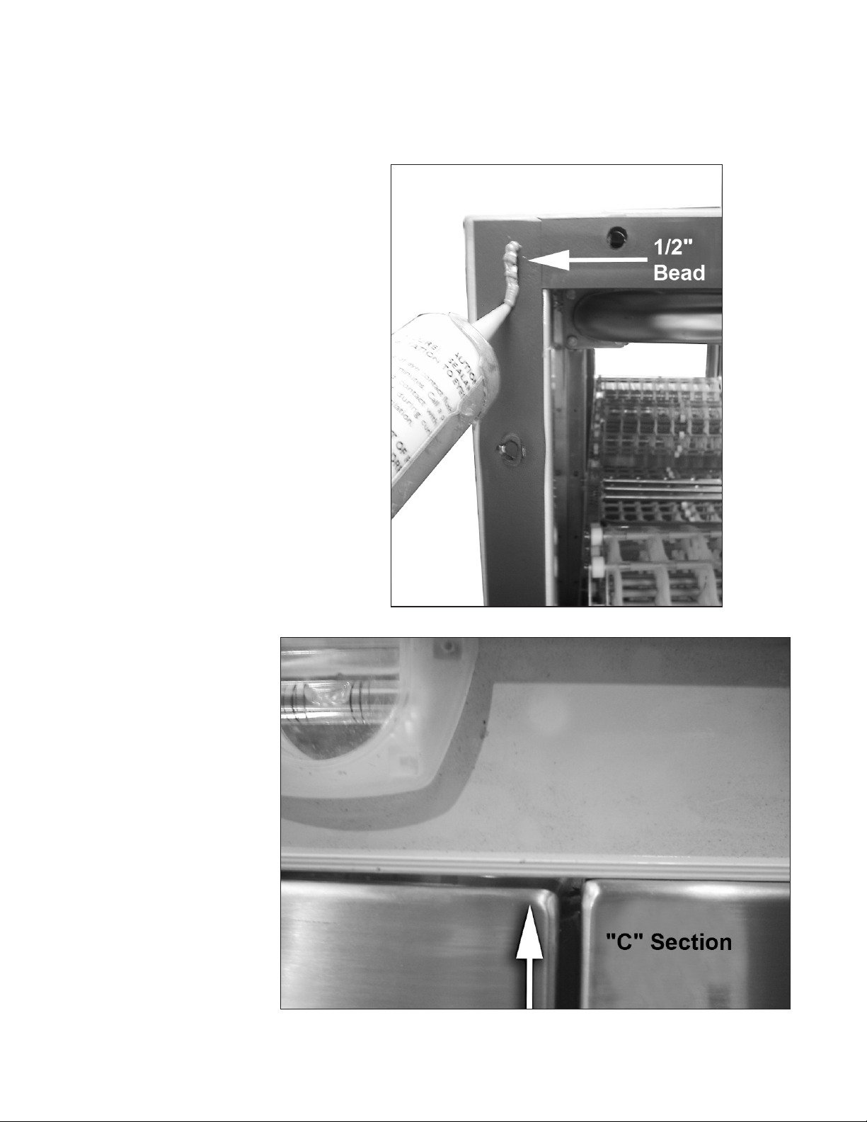
Joining the Sections
1. Apply a 1/2" bead of FOOD GRADE
sealant to the foam gaskets on each
section.
2. Move the next section close to the "C".
Adjust the feet of this section to align
the 20 bolt holes around the hood.
3. Slide the connecting hoses and
clamps on drain pipes and cross-ow
pipes. Do not tighten
at this time.
4. Level each section side to side and
front to back making sure the section
connecting bolt holes align.
5. Make sure the sections are adjusted
to the same height.
8
Page 17
1. Bolt all the HOOD sections
together with twenty (20),
5/16-18 X 3/4" bolts,
lockwashers and nuts
included in the hardware kit.
2. Tighten the hood bolts in
a cross-pattern to pull the
sections together.
3. Silicon sealant should
squeeze out of the section
joints.
4. Bolt the section bases
together using three (3) 1/213 X 1" bolts, lockwashers,
and nuts from the hardware
kit.
Section Assembly: Step by Step
Installation
Joining the Sections
5. Recheck the level of the
assembled sections and
adjust as needed to achieve
a level line between the
joined sections.
9
Page 18
Installation
Tracks are Level
Tracks are not Level
Installation
Track Alignment
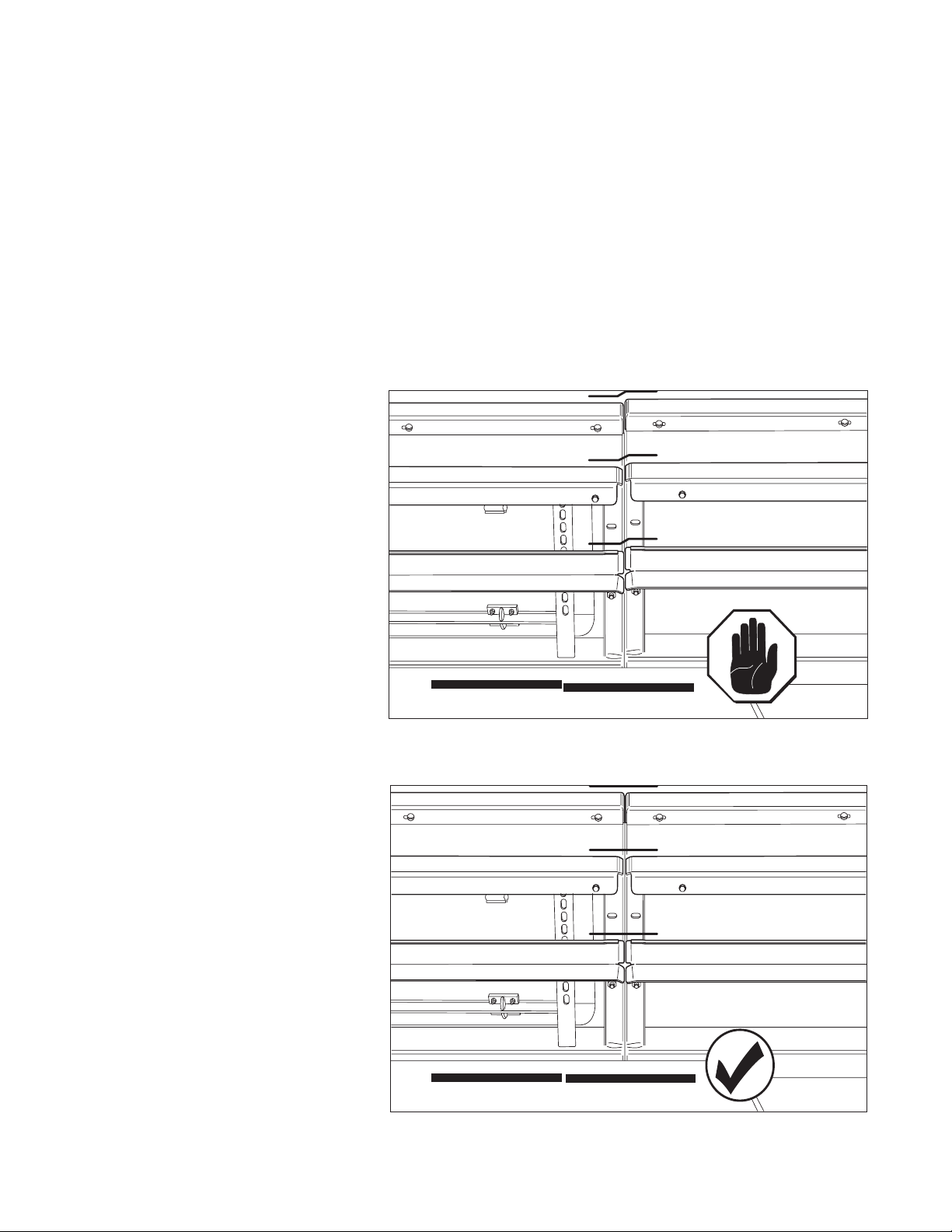
The conveyor belt is supported by tracks inside each section of the dishwasher. These tracks must be
level when the sections are joined. If the tracks are not level then the level of the joined sections should
be re-checked and adjusted so that the tracks are level. The track mounting bolts may be loosened and
a small amount if adjustment can be made. Make sure the dishwasher sections are level before adjusting
the mounting of the tracks.
1. There are upper and lower
conveyor belt tracks.
2. Check the alignment of both sets
of tracks between each section
of the dishwasher.
3. Refer to the illustrations to the
right and verify the tracks are
level as shown.
4. Re-level the dishwasher sections
until the tracks are level.
5. Recheck the level of the conveyor
belt tracks.
6. Make any nal adjustments by
loosening the track mounting and
adjusting as necessary.
7. The tracks must be aligned and
level before installing the
conveyor belt.
10
Page 19
When the dishwasher sections and the tracks are
level then the dishwasher section joints inside the
dishwasher must be capped by a u-clip that is
specifically designed to seal the joints and prevent
water leaks between the dishwasher sections.
1. Make sure the dishwasher hood and base
section joints have a section gasket
installed.
2. If the gasket is missing, then the sections
must be broken, a gasket installed, siliconed
and the sections bolted and leveled again.
The dishwasher section U-clips cannot be
installed before the section gaskets are
installed and the sections bolted together.
ATTENTION
Installation
Installation
Section Joint U-clips
1
2
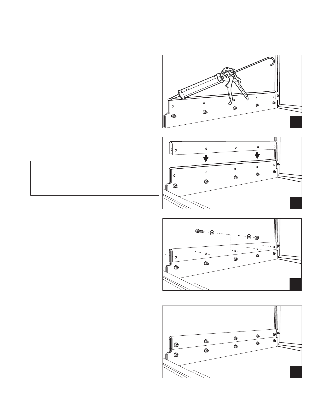
3. Refer to the illustrations to the right.
Apply a 1/2"/12mm bead of silicon at the
section seam.
4. Slide the U-clip over the seam and align
the bolt holes between the seam and the
U-clip.
5. Bolt the U-clip using 5/16-18 x 1"
bolts, washers and locknuts included in
the hardware kit.
6. Wipe any excess silicon that may have
squeezed out of the U-clip joint.
7. The U-clip is P/N 329758.
3
4
11
Page 20

Installation
Installation
Bafes
Refer to the photos to the right and below.
The right-hand photo shows a U-clip installed on
the section joint.
Above the U-clip is tank baffle which redirects
water flow back into the proper tank.
Baffles are installed in the dishwasher prior to
shipment.
1. Each section joint has a set of two bafes,
one on each side of the section joint.
2. After the U-clips are installed on the section
joint, check that the bafes are installed
correctly.
3. The bafes should angle downward so that
water is deected into the tank directly
below the bafe.
4. Make sure that the bafes move freely
without binding.
U-clip installed on section joint with baffle shown above.
12
Tank Baffle shown outside the dishwasher prior to installation at the factory.
Page 21
WARNING:
Moving Conveyor Parts may cause INJURY OR DEATH.
Keep hands and clothing clear of the conveyor when the
conveyor is moving.
USE EXTREME CAUTION WHEN THE CONVEYOR
IS MOVING.
The load and the unload sections of the dishwasher
are equipped with removable panels which need to
be removed prior to assembling the conveyor belt.
1. Start at the unload end of the machine and note
the location of the top and side panels
Installation
Installation
Assembling the Conveyor Belt
2. Lift the top panel straight up and off the end of
load section.
3. Lift the end panel straight up. Note the guides
on the sides of the hood as you lift the end
panel up and off.
4. Lift the side panels of of the right and left sides
of the dishwasher load end.
5. Moving to the unload end of the dishwasher,
lift the end panel straight up and off the end
of the machine. Remove the bolts holding the
rectangular cover protecting the drive gear
assembly. Pull the cover off of the dishwasher.
6. Set the panels and covers aside and retain the
mounting hardware.
1
2
3
5
4
13
Page 22
Installation
Installation
Assembling the Conveyor Belt
The conveyor belt may be shipped separately
from the dishwasher on pallets or it may be rolled
up inside of the dishwasher. In either case, the
installation is the same.
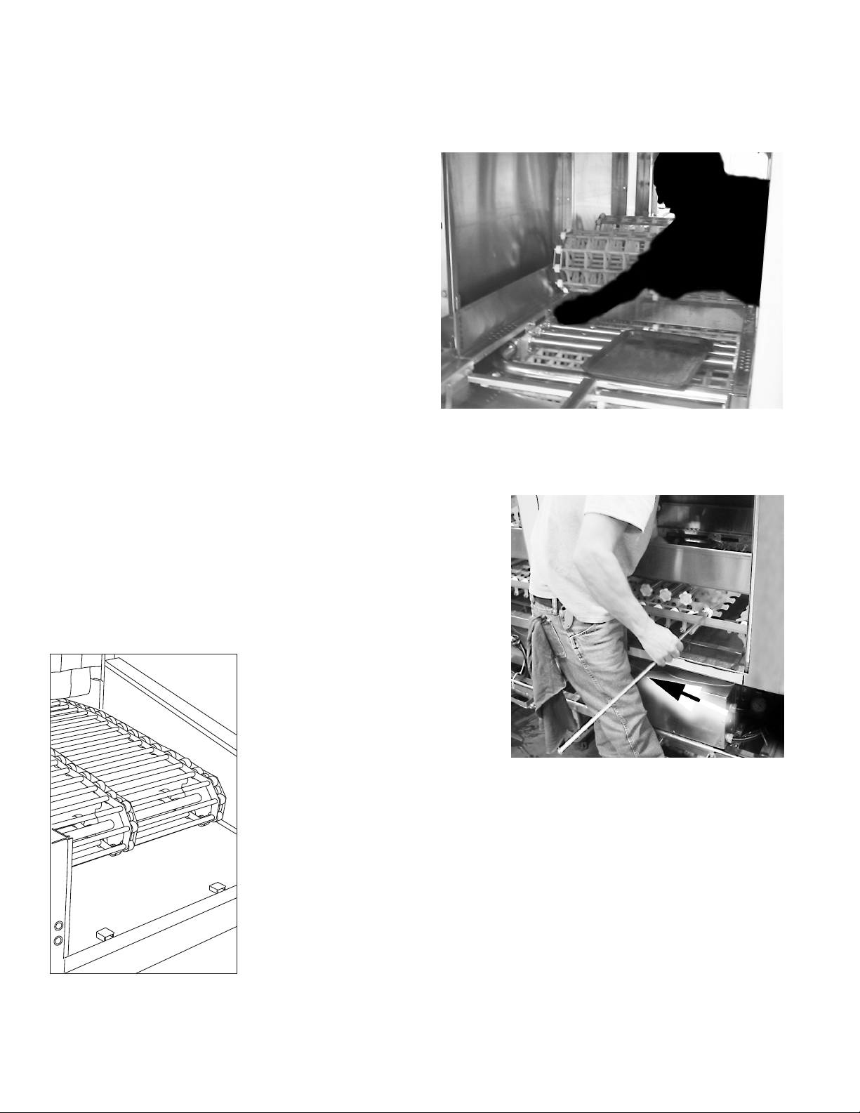
1. Start at the unload end of the machine and pull
the conveyor belt around the end sprockets
until approximately 1.5 feet/76.2 cm of belt
rests on the upper track of the dishwasher.
2. Pull a section of belt to the next section along
the upper track into the unload end.
Roll the first section of conveyor belt
from the unload section toward the unload section.
3. Join the belt sections together by feeding a
conveyor rod through the links, spacers, and
rollers. Install a cotter pin on each end of the
rod to secure the assembly.
4. Use an assembled rod section on the belt as
a guide for the placement of the spacers, etc.,
continue this procedure until the conveyor belt
is assembled in a complete loop.
Connect the conveyor belt sections with
a rod, spacers, and washers included
in the hardware kit.
The assembled belt should
form a complete loop.
14
Page 23
Installation
Roller seated
in sprocket
Steel links do not
rub sprocket
Installation
Assembling the Conveyor Belt
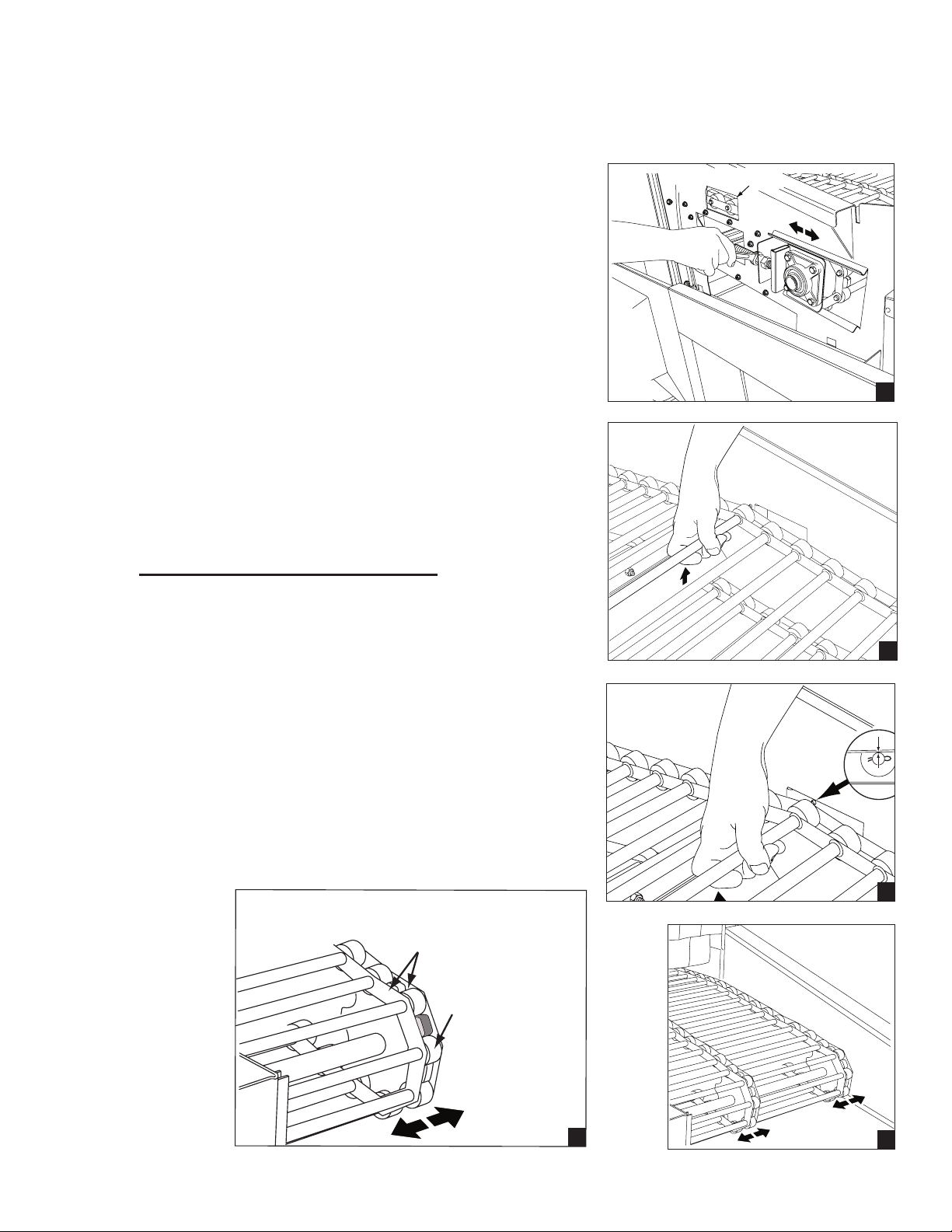
1. The take-up assemblies are located on either side of the
load end conveyor shaft as shown in (A).
2. Adjust the conveyor belt tension at the load end.
Loosen the adjusting bolt locknuts then turn the
adjusting bolts CW to tighten the belt.
3. Make sure the belt tension is even on both sides.
4. Check the slack of the lower portion of the belt. The
lower belt must not sag.
5. Continue to adjust belt tension as you manually remove
lower belt slack until the lower slack is minimized.
6. Check the belt tension by lifting the upper conveyor belt
at the load end of the dishwasher as shown in (B).
7. The proper belt tension is achieved when the top of the
conveyor belt rods are even with the top of the belt
access hole as shown in (C).
DO NOT OVERTIGHTEN THE BELT.
8. Tighten the adjusting bolt locknuts on each take-up
assembly to hold the belt adjustment.
Belt Access Hole
A
9. Check that the conveyor belt tracks evenly on all
of the conveyor drive sprockets during operation and
adjust the take-up assemblies as required
as shown in (D).
10. Proper tracking requires that the rollers seat evenly
in the conveyor belt drive sprockets. The metal links
on the conveyor belt must not rub the sides of the
belt sprockets as shown in (E).
B
C
E
D
15
Page 24

Installation
Installation
Adjusting the Conveyor Belt Clutch
1. Locate the conveyor belt drive assembly located
at the unload end of the dishwasher.
2. Refer to the photos on the right and note the
arrangement of the drive clutch components.
3. Locate the clutch kit included in the hardware
kit and install the components as shown in the
illustration below. Tighten the clutch retaining
nut.
4. Proper clutch adjustment is correct if a 185lbs.
person can stall the belt when safely pulling
against the moving conveyor belt.
5. NEVER LUBRICATE THE CLUTCH ASSEMBLY.
ATTENTION
CHECK THE BELT TENSION IN 3 WEEKS
AND RE-ADJUST AS REQUIRED.
1
ATTENTION
The ID of first clutch disk is larger than
the bore of the drive shaft.
Make sure the first disk rests on the shoulder
of the drive shaft to ensure correct clutch
assembly.
8
4
5
2
3
Item Part No. Description Qty.
1 100485-1 Hub, Torque Limiter #350A 1
2 104271 Bushing, Torque #350A 1
3 108013 Sprocket, 350AG26 1
4 100485-2 Friction Disc, #350A Clutch 2
5 100485-2 Pressure Plate, #350A 1
6 100485-3 Spring Washer #350A 2
7 100485-5 Lockwasher, #350A 1
8 100485-6 Adjusting Nut, #350A 1
6
7
6
16
Page 25
CAUTION
The Variable Frequency Drive (VFD)
is a solid-state motor control.
Changing the factory settings without
prior authorization by the factory will void the
warranty of the VFD and the Dishwasher.
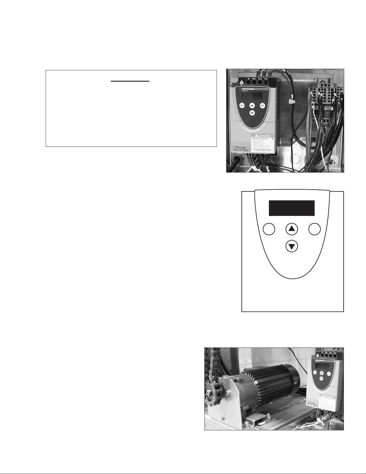
The conveyor belt speed is set at the factory to
run in the three operation modes. The modes are
selected by pressing a mode switch located on
the top-mounted control cabinet. The modes are:
Energy Saver Mode
Normal Mode
Installation
Installation
Inverter Conveyor Drive Motor Speed Control
VFD DISPLAY
ESC ENT
Fast Mode
When the conveyor belt is moving normally, the VFD Display
will indicate a number on the display that is calibrated at the
factory.
Variable Frequency Drive (VFD)
shown with the Conveyor Drive Motor
Variable Frequency Drive (VFD)
for the Conveyor Drive Motor
17
Page 26
Installation
Installation
Plumbing Connections
ATTENTION
Plumbing connections should be made by
qualified personnel who will follow all local
plumbing, safety, and sanitary codes and
regulations.
1. The specic water requirements for the
installation of the dishwasher are listed on
the Plumbing and Electrical Diagram (P& E)
that was provided prior to the installation.
2. It is recommended that the Installation
Supervisor inspects the position, level and
alignment of the piping prior to making the
connections.
A
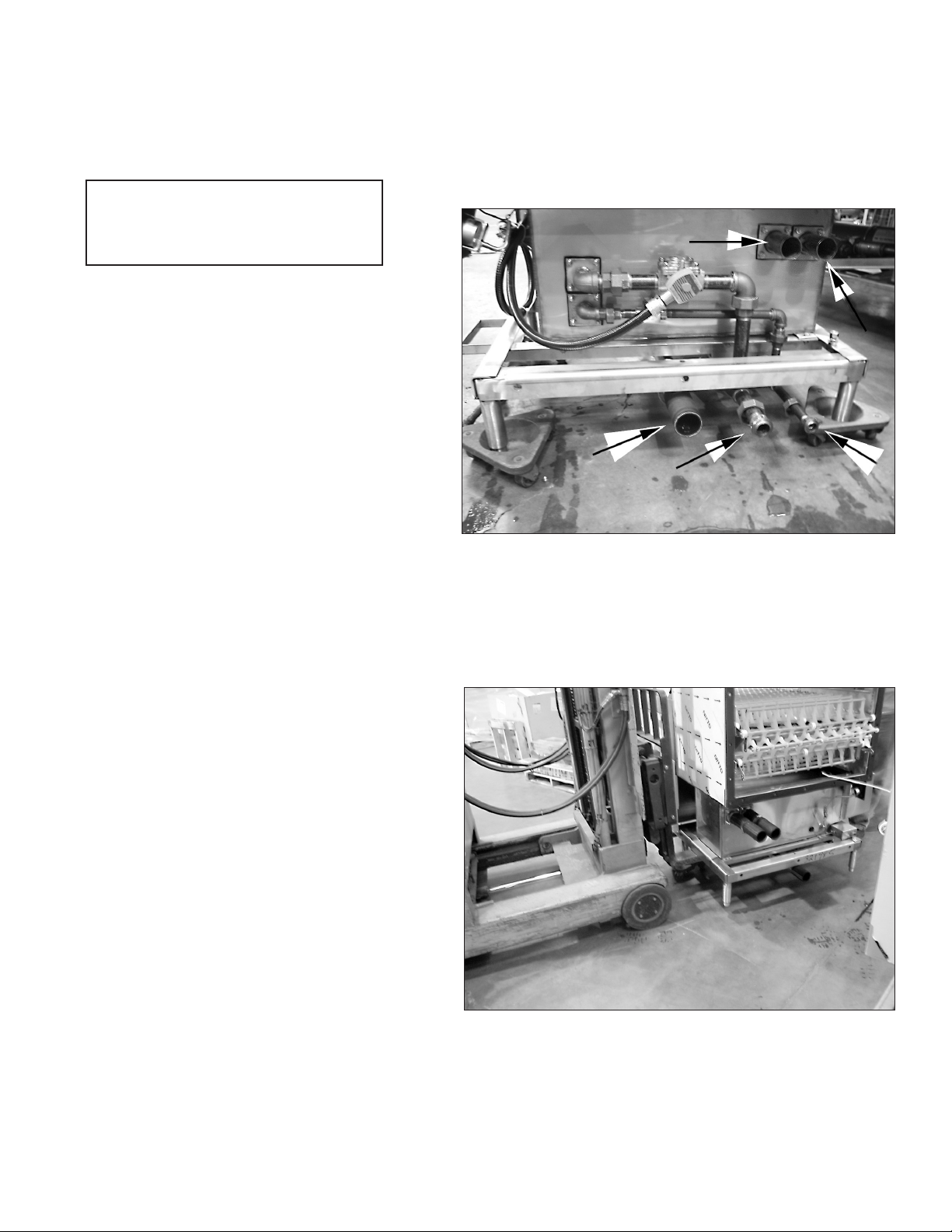
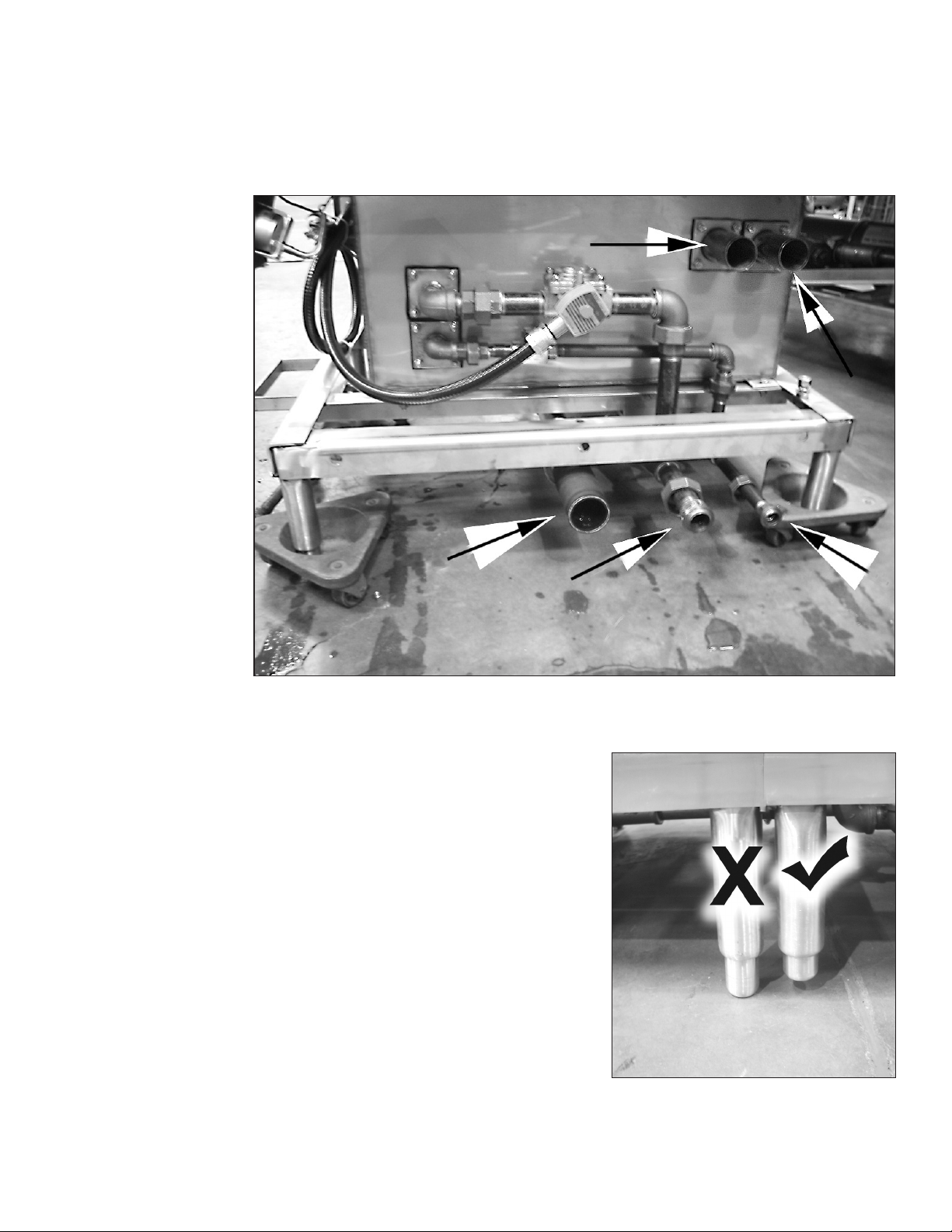
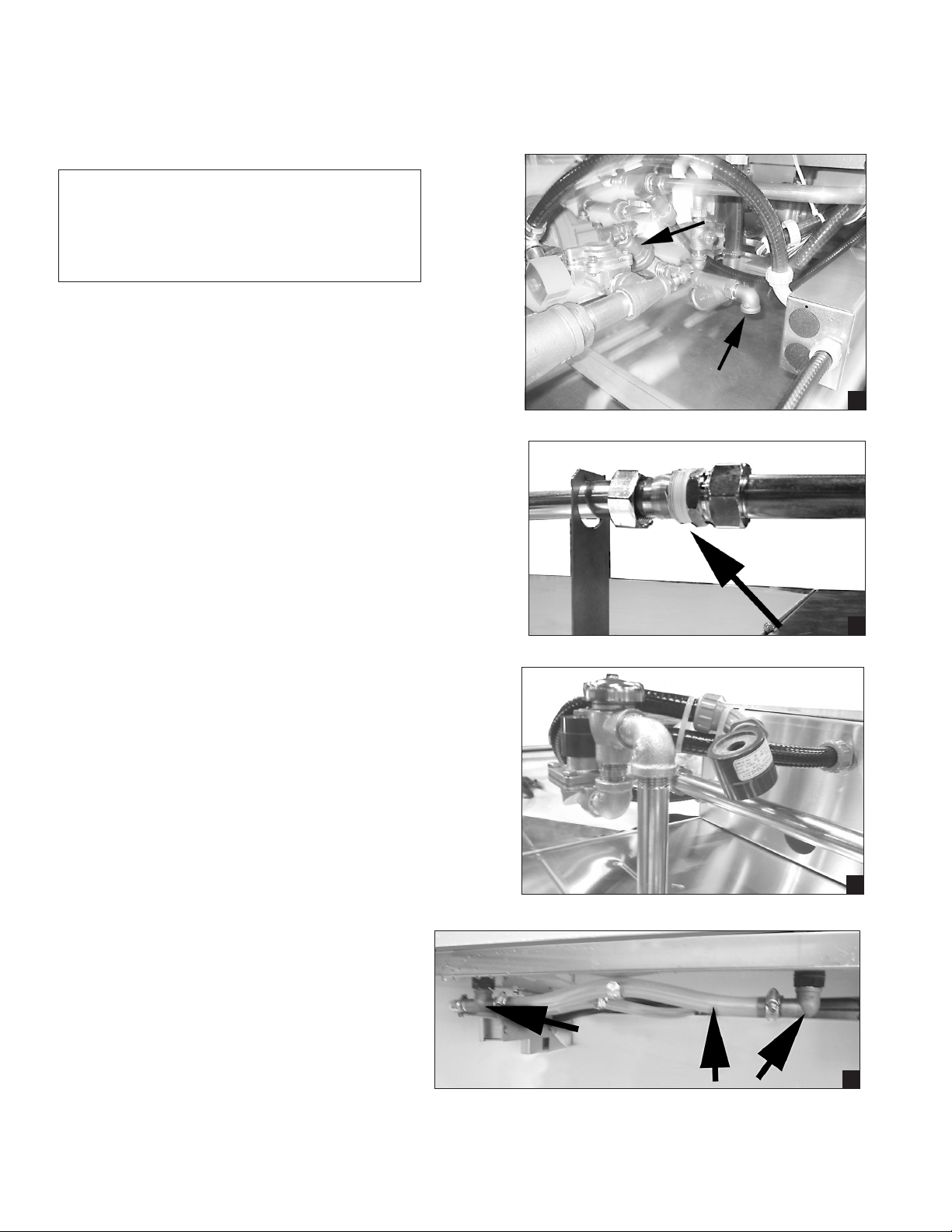
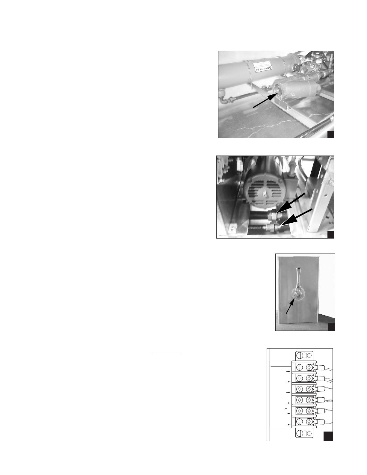
3. The main water supply connection is located
underneath the unload section of the
dishwasher adjacent to the pressure regulating
valve (PRV) as shown in (A).
4. The PRV must be adjusted to provide a
owing pressure of between
20-22 PSI / 138-152 kPa.
5. Tighten the dishwasher ll piping compression
ttings located on the top of the dishwasher.
Use Teon tape on the threads to ensure a
water-tight joint as shown in (B).
6. Remove the shipping ties that hold the ll water
solenoid valve coils and mount the coils on the
solenoid valve stems as shown in (C).
7. Assemble the ushing nozzle piping located
on the load-end of the dishwasher making sure
that the nozzles point towards the dishwasher
entrance as shown in (D).
B
C
18
D
Page 27
Installation
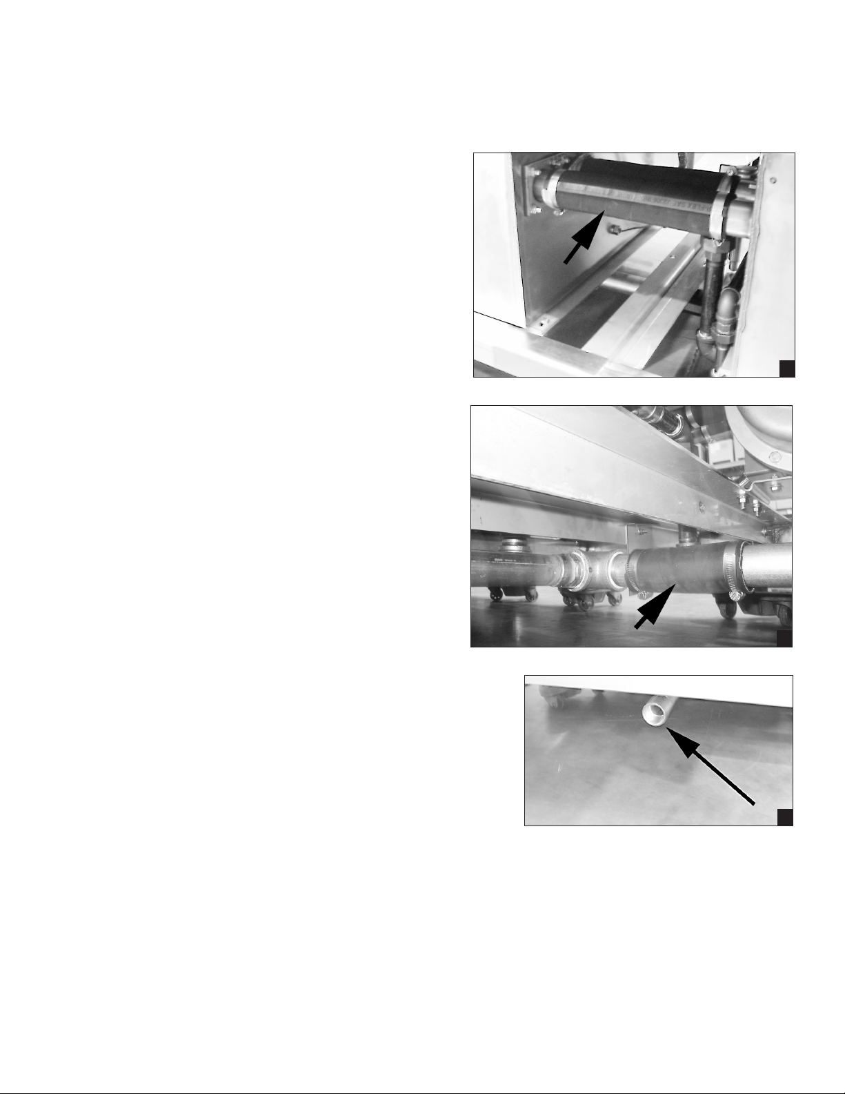
8. Connect the cross-ow piping between
the tank sections using the rubber hoses
supplied. Make sure that all hose clamps
are tight and secure as shown in (E).
9. Make sure all drain ttings are tight then
connect the drain trunk sections using
the rubber hoses supplied as shown in (F).
10. Connect the dishwasher drain outlet piping
located underneath the load-end of the
dishwasher. The dishwasher drain line
is a 2" NPT connection as shown in (G).
11. Check the water and drain connections
during the initial start-up of the dishwasher
to ensure that supply and drain piping
does not leak.
Installation
Plumbing Connections
E
12. The building drain system must be of
sufcient size and capacity to allow the
dishwasher to drain completely without
restriction.
13. Make sure that the dishwasher drains
properly during the initial start-up.
14. Make sure that any foreign material is
removed from inside, on top of, and
underneath the dishwasher when the
plumbing and drain connections are
complete.
F
G
19
Page 28
Installation
Installation
Steam Connections
1. The specic steam requirements for the
installation of the dishwasher are listed on
the Plumbing and Electrical Diagram
(P& E) that was provided prior to the installation.
2. It is recommended that the Installation Supervisor
inspects the position, level and alignment of the
piping prior to making the connections.
3. The main steam supply connection is located
underneath the unload section of the dishwasher
as shown in (A).
4. Connect the steam supply piping and steam
condensate lines (B) located between the dishwasher sections. Make sure all ttings are tight.
5. The steam condensate line may be run to a drain
or to a boiler return line. If plumbing to a boiler
return line make sure that there is no backpressure on the condensate line. Connections
to the building condensate return is performed by
others.
Vent Connections
1. The specic venting requirements for the installation of the dishwasher are
listed on the Plumbing and Electrical Diagram (P& E) that was provided prior
to the installation. Vent connections to the dishwasher are performed by
others.
A
B
2. Install the dishwasher vent stacks on the load and unload end of the
dishwasher so that the vent handles are facing the front of the dishwasher.
3. Set the vent damper adjustment handles in the vertical position as shown in
(A). This sets the vent damper in the fully open position.
4. There is a vent fan signal connection point located inside the top-mounted
control cabinet to interlock the building vent system with the dishwasher
operation. See (B).
NOTE:
This is a 24VAC signal only and cannot be used to power vent
motors or other control circuits.
20
SIGNAL ONLY
VENT FAN
120V
COMMON
RINSE AID
120V
COMMON
DETERGENT
120V
A
B
Page 29
Installation
Electrical Connections
1. The specic electrical requirements for the
installation of the dishwasher are listed on
the Plumbing and Electrical Diagram
(P& E) that was provided prior to the installation.
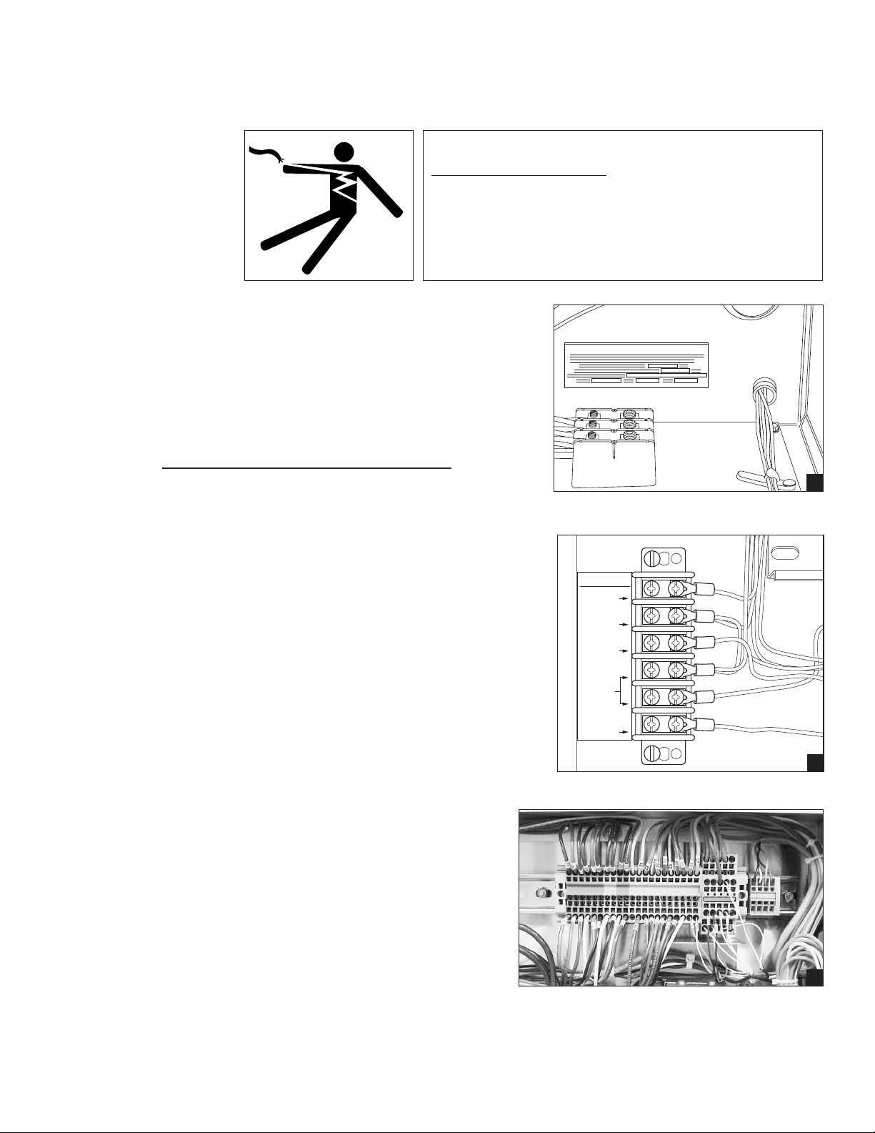
2. The main power supply connection for the
dishwasher (excluding electric booster power) is
made at the main terminal block as shown in (A).
The Machine Electrical Connection Data Plate is
mounted adjacent to the main terminal block and
contains electrical specications for the
connection.
Installation
WARNING:
Electrocution or serious injury may result when working on an
energized circuit.
Disconnect power at the main breaker or service disconnect
switch before working on the circuit.
Lock-out and tag the breaker to indicate that work is being
performed on the circuit.
MACHINE ELECTRICAL CONNECTION
A
3. A separate terminal block (B) is located inside
the top-mounted control cabinet which provides
signal voltages for chemical dispensing
equipment or vent fan control if required.
4. The main power connection for the electric
booster (Not Shown) is a separate connection
and is located inside the booster control box.
The box is typically installed on the base of
unload section. The box can also be located
on the top of the dishwasher if specied.
5. Electrical connections between dishwasher
sections are made in wireway boxes (C) that
are mounted on the base of each section.
6. Remove the covers of the wireway boxes and
indentify connecting wires and terminal blocks.
7. Unroll any exible conduits that were
disconnected from the wireway prior to shipment
and re-route them into the wireway boxes.
8. Refer to the dishwasher electrical schematic and
re-connect the wires between the sections using
the hardware supplied.
SIGNAL ONLY
VENT FAN
120V
COMMON
RINSE AID
120V
COMMON
DETERGENT
120V
B
C
9. Re-install the wireway box covers.
21
Page 30

Installation
Installation
Sealing Section Joints
Machine section joints must be sealed using a food-grade
silicon sealant. Several tubes of approved sealant were
included in the installation hardware kit.
Study the photos on the right.
The top photo shows an incorrectly sealed joint. Note that the
joint seal has a valley indicating that insufficient sealant was
applied.
The bottom photo shows a correctly sealed joint. The joint seal
is filled and the transition between the sections is shallow.
To seal the section joints:
1. Make sure the machine sections are level, all utilities
and cross-connections are made and the sections are
bolted together.
2. Clean the joint with isopropyl alcohol to remove dust,
oil lm, and other contaminants.
3. Mask the joint edges with a quick-release masking
tape.
4. Apply a 1/8" bead of food-grade silicon sealant
using moderate pressure on the caulking gun to
ensure the sealant lls the joint.
5. Wait 1 minute for the sealant surface to rm slightly
(but before a skin forms), then wipe the joint with a
clean damp cloth.
Note:
If the sealant dries longer than 1 minute, do not try to wipe
the joint. Allow the sealant 30 minutes to dry, then cut the
sealant out of the joint and reseal the joint.
A
B
6. Wait 10-seconds after wiping the joint, then remove the
masking tape.
7. The joints can be cleaned and trimmed in about 1 hour.
22
C
Page 31

Installation
Optional Blower-Dryer Installation
FOR COMPLETE BLOWER-DRYER INSTALLATION INSTRUCTIONS
REFER TO THE BLOWER-DRYER SERVICE MANUAL, P/N 114316,
SHIPPED WITH THE BLOWER-DRYER ASSEMBLY
1. The blower dryer comes in electric or
steam.
2. It ships on a separate pallet.
The vent cowl and mounting hardware are
included in the
accessories box and hardware
kit.
3. Lift the blower dryer off the pallet
with a forklift and place on the
end of the unload section.
4. If a forklift is not available, then
four (4) men are needed to lift
and install the unit manually.
5. Bolt the blower dryer in place using the
5/16-18 X 3/4" bolts, at washers, and lock
washers from the hardware kit.
6. Fasten the vent cowl on the discharge end
of the blower dryer using the 1/4-20 plain
nuts, at washers, and lock washers from
the hardware kit.
7. Connect the ex-tite conduit to the junction
box located at the rear of the dishwasher.
8. Match wire numbers in the junction box
and connect with wire nuts.
9. Close the junction box.
10. Install the cowl to the end of the
blower dryer.
23
Page 32

Installation
Installation
Check List
Perform the following checks and adjustments before placing the machine into service.
1. Check the interior of the machine and remove any foreign material.
2. Check the scrap screens, pump strainers and scrap baskets are properly installed.
3. Check the exterior of the machine — make sure that the conveyor belt is free of tape and foreign
material.
4. Vent stacks must be placed on the hood with vent handles facing the front of the dishwasher
5. Open the water supply valves. Check for leaks and take corrective action as required.
6. Open the steam supply valves (if applicable). Check for leaks and take corrective action if required.
7. Turn the main power on at the breaker panel or fused disconnect switch.
8. Flip the Power Switch on the front of the Control Cabinet to the "ON" position.
The machine will begin to ll with water. The water will shut off automatically.
9. Check for leaks and take corrective action if required.
10. Allow sufcient time for the tank heat to reach operating temperature.
then check that the digital temperature meters indicate the proper temperature readings.
11. Move the conveyor shut-off shelf located at the end of the unload section toward the load end of
the machine. This resets the automatic conveyor stop system.
12. Press each mode switch and then the stop switch in succession to check conveyor belt drive
operation.
13. Open each door to ensure the door safety switches shut the machine off.
14. Operate the conveyor shut-off assembly to ensure the conveyor stops when operated.
15. Check the direction of rotation of the conveyor belt by observing the direction arrow decal on the
large conveyor drive sprocket. The sprocket is located on the side of the unload section.
If rotation direction is incorrect, reverse wires L1 and L2 on the disconnect switch side of the main
electrical connection terminal block located inside the control cabinet.
16. Check the conveyor drive clutch adjustment.
The clutch should be CHECKED AND ADJUSTED MONTHLY.
17. Check the alignment of the conveyor belt.
18. Check the Energy Sentinel (idle pump shut-off) by placing a tray or dish on the moving conveyor
belt. The pumps should start when the object breaks the infrared beam on the entrance end
of the dishwasher.
19. Make sure the panels are properly installed. The panels are marked with location numbers and
should match the numbers located on the dishwasher.
20. Make sure the curtains are properly installed.
21. Turn the dishwasher power switch to the OFF position.
22. Open the dishwasher drains and make sure the building drain system handles the drain flow.
23. Make sure the dish room is neat and clean.
24
Page 33

Operation
Operation
Introduction
The flight-type upright conveyor dishwasher consists of a series of wash tanks designed to clean a variety
of soiled ware moving through the tanks on a conveyor belt. Refer to the illustration below for a general
description of the machine.
Dishwasher Tanks and Options:
1. Load - Soiled ware is sorted and loaded on the conveyor belt.
Wares enter the dishwasher.
2. Prewash Tank - Soiled wares are ushed to remove large particles and to loosen
heavy food-soils.
3. Wash Tank - Wares are washed with hot water and detergent.
4. Power Rinse Tank - Wares are rinsed with hot water to remove detergent and any
remaining food soils.
5. Quad Rinse - Auxiliary rinse begins the hot water sanitization process then
the nal rinse completes the hot water sanitization process.
6. Unload - Clean wares exit the dishwasher and ash dry on the conveyor belt.
7. Blower Dryer Option - Hot air is forced over wares to speed drying.
8. Heat Recovery Option - Hot air exhaust is recycled to raise the incoming water temperature
for the nal rinse booster reducing energy costs.
Direction of Travel
Quad
Rinse
5
8
Power
Rinse
4
Wash
Pre-
Wash
23
Load
1
7
Heat Recovery
Blower
Unload
6
Dryer
25
Page 34

Operation
Operation
Curtain Placement Diagram
Proper curtain placement is essential for the proper operation of the dishwasher. Refer to the diagram
below and make sure the curtains are installed correctly before operating the machine.
Load
Install the curtain with
the Part No. and short
flaps facing the load end
L
of the machine
M
MM
S
L
Prewash
Wash
Rinse
Power
Quad
Rinse
114111
L
114111
114111
112445
112445
19"
Long Curtain
M
14"
Medium Curtain
26
Unload
* * *
204949
204949
S
10"
Short Curtain
* When ordering parts, refer to Replacement Service Parts Section for correct curtain part nos.
Page 35

Operation
Operation Summary
The steps below summarize the basic operation of the dishwasher.
Detailed explanations follow this summery.
WARNING:
Moving Conveyor Parts may cause INJURY OR DEATH.
Keep hands and clothing clear of the conveyor when the
conveyor is moving.
USE EXTREME CAUTION WHEN THE CONVEYOR
IS MOVING.
1. Check the chemical connections and chemical containers are installed and ready for operation,
(Consult your chemical supplier for instructions).
Operation
2. Check the interior of the dishwasher for foreign objects and remove.
3. Turn on the water supply to the dishwasher.
4. Turn on the main power switch at the building service disconnect switch.
5. Close all drains.
6. Make sure oats, overows, drain screens, and pump intake screens are clean and in place.
7. Make sure all spray arm assemblies are in place and secure.
8. Make sure curtains are properly installed.
9. Make sure all doors are closed.
10. Make sure the conveyor shut-off shelf is in the ON position.
11. Push the dishwasher main power switch to the ON position.
- The machine will begin to ll with water.
12. If equipped, turn the Optional Blower Dryer Switch ON.
- The blower dryer runs whenever the pumps run.
13. Monitor the digital temperature gauges for the proper tank temperature readings:
Prewash less than 160°F
Wash minimum of 150°F
Rinse minimum of 160°F
Auxiliary minimum of 160°F
Final Rinse INDICATES OFF when nal rinse is not running
minimum of 180°F when nal rinse is running
27
Page 36

Operation
Operation
Summery of Operation
The steps below explain the basic operation of the dishwasher. Detailed instructions follow this summery.
14. When wash tank temperature readings are correct then push the NORMAL mode selector switch.
- The green LED will illuminate and the conveyor will start.
Select the FAST mode selector switch.
- The Fast LED will illuminate and the conveyor speed will increase.
15. Scrap and pre-rinse wares, sort and place on the conveyor belt to wash. When the wares break the
infrared beam at the entrance of the wash tunnel:
- The wash pumps run.
- If equipped, the optional blower dryer runs.
- If equipped, the optional Heat Recovery Unit runs.
NOTE: The dishwasher will run automatically as long as wares break the infrared beam.
The automatic time cycle ends when the last item placed on the belt has been washed,
sanitized and exited the machine.
16. Wares move on the conveyor belt through the wash tanks and the nal rinse section for sanitizing.
The blower dryer aids the drying of the wares.
The heat recovery unit captures residual heat from the dishwasher reducing energy costs.
17. Clean wares exit the dishwasher. If wares touch the conveyor shut-off shelf:
- The automatic timed cycle pauses.
- The conveyor belt stops.
- The blower dryer operates for 30 additional seconds and stops.
- The wash pumps stop.
18. Clear the belt area of wares and return the conveyor shut-off shelf to the ON position.
- The automatic timed cycle resumes.
- The conveyor belt runs.
- The wash pumps run.
- The blower dryer runs.
- The heat recovery unit runs.
19. When the last item placed on the belt exits the machine:
- Remove the item.
- The pumps automatically stop.
- The blower dryer stops after running 30 more seconds.
- The heat recovery unit stops.
- The conveyor belt continues to run.
NOTE: The machine operation will stop whenever the STOP button on the main control cabinet or
a remote stop/start station is pressed. Operation will resume when the remote start
button is pressed or a Mode Switch on the control cabinet is pressed.
The dishwasher conveyor, pumps, and blower dryer turn off whenever a door is opened.
Push a start button or mode switch to resume operation.
28
Page 37

Operation
Operation
Checking Drains, Floats, Overflows, and Pump Intake Screens
1. Close all drains.
2. Make sure oats, overows, drain screens,
and pump intake screens are clean and in
place.
3. The pump intake screens are removed by
sliding them up and out.
Make sure they are in place and secure.
4. Inspect the bottom of the dishwasher tanks
to ensure they are clear of foreign objects.
1
2
3
29
Page 38

Operation
Operation
Installing Curtains
1. Place the curtains in the dishwasher making
sure the short aps face the load end
of the machine.
2. Locate the curtain hooks in each section.
3. Place the curtain rod in the rear hook, then
lift the opposite end of the curtain rod and
place it in the front hook.
4. Place the 19" long curtains at each end
of the dishwasher.
5. Place the 14" center curtains in each section.
6. Place the 10" nal rinse curtain between
the nal rinse and auxiliary rinse pipes.
30
Page 39

Operation
Operation
Installing Spray Arm Assemblies
1. Check the upper and lower wash arm manifold
o-rings to make sure they are in place and in
good condition.
2. Install the upper wash arm assemblies.
3. The auxiliary rinse section is equipped with an
upper and lower rinse arm.
4. Install the lower wash arm assemblies.
1
5. Make sure all wash arm assemblies are
locked in place.
2
3
31
Page 40

Operation
Upper Spray Arm Assembly
Operation
Installing Spray Arm Assemblies (continued)
Locking
Slot
Locking Slot
Lock
the
Release
Push the Upper spray arm assembly into place. Push the spray arm release down to lock the spray
arm assembly.
Release
Locks
Release
Lock
Locking
Slot
Locking
Slot
Tab
prevents
spray arm
from
dropping
Push the release up to unlock the spray arm
assembly.
32
Tab
prevents
spray arm
from
dropping
Upper Spray Arm Assembly
Pull the spray arm assembly out of the dishwasher.
Page 41

Installing Spray Arm Assemblies Auxiliary Rinse Spray Pipes
There are 2 removable auxiliary rinse spray pipes in the auxiliary rinse section.
1. Make sure the upper and lower auxiliary
rinse spray pipe gaskets are in place.
The square-shaped pipe gasket is installed
rst and the round o-ring second.
2. Position the spray pipe so the rinse
nozzles point toward 10 o'clock.
3. Push the rinse pipe forward.
4. Turn the auxiliary rinse pipe clockwise
1/4 turn to lock it in place.
Operation
Operation
Note:
The final rinse pipes are permanently
installed and do not require assembly.
The square-shaped gasket is installed first and the round o-ring
is installed second.
Push the auxiliary rinse arm forward, then rotate the arm
clockwise 1/4 turn to lock it in place.
33
Page 42

Operation
Operation
Opening and Closing Doors:
Standard Doors
1. Lift the door up, the door catch will engage
and hold the door up.
2. Slowly lower the door. The door catch
engages and holds the door up.
3. Carefully push the door catch back and
lower the door
Split Doors
4. Lift the upper door until the door
catch engages and holds the door in place.
5. Lift the lower door until the lower door
catch engages and holds the lower door
up and in front of the upper door.
6. Release the lower door catch and slide the
lower door down.
7. Release upper door catch and slide the upper
door down.
8. Release the upper door safety stop and slide the
upper door closed.
Upper Door Catch
Lower Door Catch
Standard Door
34
Split Doors
Upper Door Safety Stop
Page 43

Operation
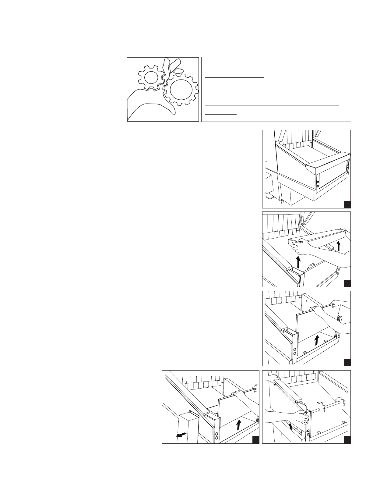
1. The scrap screens and the scrap basket
are removable and should be cleaned
periodically during normal operation and at
the end-of-the day or after 2-hours of
continuous operation.
2. The scrap bucket and the associated scrap
basket are optional equipment and may
not be installed on the dishwasher.
3. Scrap screens and scrap baskets should
be removed level to prevent food-soils from
falling into the machine during removable.
4. Open the dishwasher tank door.
Operation
Removing Scrap Screens and Scrap Basket:
5. Remove the scrap bucket cover and hang
the cover on the front of the scrap bucket.
6. Tilt the back of the scrap screen slightly up
to clear the rear screen catch.
7. Pull the scrap screen forward and out of the
dishwasher.
8. Lift the scrap basket up and out of the
machine.
9. Re-assemble in reverse order.
10. Make sure the scrap screen overlaps
the scrap basket edge to ensure food-soils
ow into the scrap basket.
35
Page 44

Operation
Operation
Control Panel Operation
Mode Indicator Lights
Power
Switch
A
Mode
Switches
B
Stop
Switch
C
Right-to-Left (R-L)
Operation Shown
Digital Temperature Display Meters
D
The top-mounted control panel contains the Power ON/OFF switch, mode selector switches and indicator
lights, stop switch and digital display temperature meters. The function of these controls are:
A Power Switch -
Turns power On and Off.
B Mode Switches and Indicators
Changes the conveyor speed and the wash system for 3 modes of operation:
Energy Saver Mode
Normal Mode
Fast Mode
C Stop Switch
Stops the conveyor.
D Digital Temperature Display Meters -
Displays the temperature in each wash tank and the temperature of the nal rinse water.
The wash tanks and the final rinse temperatures are
numerically displayed and a colored bar around the
numbers creates a visual indication of the temperature.
1. When the color of the bar is yellow and green
then the water temperature is at or above the
minimum temperature required to operate the
machine.
2. When the color of the bar is yellow then the
water temperature is below the minimum
temperature required to operate the machine.
Wait until the temperature has reached the
proper operating temperature.
36
W
O
L
L
E
Y
W
O
L
L
E
Y
G
R
E
E
N
G
R
E
E
N
Page 45

Control Panel Mode Selection
Control Switches are located on the front of the top-mounted control cabinet.
The operator can preset a mode of operation or change the preset mode while the belt is moving.
Operation
Operation
1. Power Switch
2. Energy Saver Mode Selector Switch
3. Energy Saver Mode Indicator Light
4. Normal Mode Selector Switch
5. Normal Mode Indicator Light
6. Fast Mode Selector Switch
7. Fast Mode Indicator Light
8. Conveyor Stop Switch
To operate the dishwasher in the Energy Saver mode:
1. Push the Energy Saver Mode Selector Switch.
2. The Energy Saver Indicator will illuminate.
3. The conveyor belt will run.
4. Push the Stop Switch.
5. The conveyor belt will stop.
6. The Energy Saver Mode Indicator remains
illuminated.
To operate the dishwasher in the Normal mode:
3
2
1
Power Switch is ON, no conveyor speed is selected.
Power Switch is ON, Energy Saver Mode is selected.
5
4
7
6
8
1. Push the Normal Mode Selector Switch.
2. The Energy Saver Mode Indicator will go out.
3. The Normal Mode Indicator will illuminate.
4. The conveyor belt will run.
5. Push the Stop Switch.
6. The conveyor belt will stop.
Power Switch is ON, Normal Mode is selected.
7. The Normal Mode Indicator remains illuminated.
To operate the dishwasher in the Fast mode:
1. Push the Fast Speed Selector Switch.
2. The Normal Mode Indicator will go out.
3. The Fast Mode Indicator will illuminate.
4. The conveyor belt will run.
5. Push the Stop Switch.
6. The conveyor belt will stop.
Power Switch is ON, Fast Mode is selected.
7. The Fast Mode Indicator remains illuminated.
Note: Push the Power Switch OFF and all Mode Indicator Lights go out.
Push the Power Switch ON, then push a Mode Selector Switch to begin operation.
37
Page 46

Operation
Operation
Control Panel Digital Temperature Display
Right-to-Left (R-L)
Operation Shown
The wash tanks, auxiliary rinse, and final rinse water temperatures are displayed on digital displays located
on the right-side of the control panel. The displays are labeled according to the tank or rinse water section
that is being monitored. The illustrations above and below show the arrangement for a Right-to-Left
dishwasher. The arrangement would be reversed for a Left-to-Right machine.
Digital Temperature Display Meters
The minimum temperatures shown below must be maintained when the dishwasher is washing wares. A
longer wait time or corrective measures should be taken immediately to maintain the temperatures.
Minimum
180°F
82°C
Final Rinse
Minimum
165°F
74°C
Aux. Rinse Rinse
Minimum
160°F
71°C
Minimum
150°F
66°C
Wash
No
Minimum
Required
Prewash
ATTENTION
The temperature displays must be checked repeatedly whenever the wash pumps are running and
wares are being washed to make sure that the proper temperatures are being maintained.
38
Page 47

When the conveyor belt is moving the operator can stop the belt
without using the switches on the control cabinet.
The standard Start/Stop switch station located on the load-end of the
dishwasher. An optional station is available as an option.
To operate the Start/Stop station:
1. Push the Stop switch. The conveyor belt will stop moving.
2. The timed cycle will pause.
3. Push the Start switch and the conveyor belt will run. The
timed cycle will resume where it left off.
Operation
Operation
Remote Start/Stop Stations
REMOTE
START / STOP
PUSH BUTTON
STATION
A Remote Start/Stop Station is
located on the load-end of the dishwasher.
Electric-Eyes and Idle Pump Start
The wash pumps start automatically when wares that
are placed on the conveyor belt pass through a set of
electric eyes that are mounted on the load-end of the
dishwasher. The electric eyes create an infrared beam
across the belt which, when blocked by wares, start the
wash pumps (see the photo to the right).
To start the wash pumps using the electric eyes:
1. Place wares on the belt.
2. Start the conveyor belt from the control panel
or the Start/Stop station.
3. Continuing to place wares on the conveyor belt
will activate the electric eyes and keep the wash
pumps running until wares are no longer placed
on the conveyor belt.
Note:
The wash pumps operate on a timed cycle that will automatically stop the wash pumps when the wares
have moved through the machine, are sanitized in the final rinse, and then exit the machine.
It is important that the electric eyes be cleaned regularly to prevent soils from obstructing the infrared
beam. Clean the electric eyes with a mild detergent and a soft cloth. Do not use a scouring pad.
39
Page 48

Operation
Operation
Conveyor Shut-off Shelf
WARNING:
Moving Conveyor Parts may cause INJURY OR DEATH.
Keep hands and clothing clear of the conveyor when the
conveyor is moving.
USE EXTREME CAUTION WHEN THE CONVEYOR
IS MOVING.
The Conveyor Shut-off Shelf is designed to stop the
conveyor belt when wares traveling on the conveyor belt
reach the end of the unload section. This prevents wares
from being damaged and prevents the conveyor belt from
jamming.The Shut-off Shelf is located on the extreme end
of the un-load end section of the dishwasher.
The Conveyor Shut-off Shelf functions in the following way:
1. When wares contact the shut-off shelf the shelf
pivots backward stopping the conveyor belt.
2. The shut-off shelf also will stop the optional
blower-dryer heat off if the machine is equipped
with the blower-dryer.
3. The wash pumps continue to run when the
conveyor belt stops
4. The machine operator should remove the wares
on the unload section of the belt making sure
that no wares have fallen below the conveyor
belt.
5. In the event that wares have fallen below the belt,
the operator must turn power off at the control
panel and then remove any wares. The machine
can be restarted when the wares are clear.
6. The conveyor belt will not run until the conveyor
shut-off shelf is moved back to the RUN position
as shown in the photos to the right.
Conveyor Shut-off shelf in the RUN position
Conveyor Shut-off shelf in the STOP position
40
Page 49

Cleaning
Cleaning
After each meal period or every 2 hours of operation
1. Turn POWER OFF.
2. Open the drain handles and drain the dishwasher.
3. Open the dishwasher doors, check that the curtains are in place and secure.
4. Check the conveyor belt for any wares that may have fallen down into the belt and remove.
5. Flush any accumulated soils from the load section tank bottom to the scrap screens at the end of
the load end of the dishwasher.
6. Remove the scrap baskets, (if equipped), and scrap screens.
7. Flush the scrap screens in a sink. Do not strike the scrap screens on hard surfaces.
8. Back ush the scrap screens with water.
9. Inspect the pump intake screens, remove and clean if necessary.
10. Inspect the tank drain screens and ush if necessary.
11. Re-assemble the dishwasher in reverse order.
12. Close the drains and the dishwasher doors.
13. Turn the dishwasher power ON.
14. Wait for the tank temperatures to reach operating temperatures, then return to normal operation.
41
Page 50

Cleaning
Cleaning (continued)
At the end of the day.
1. Repeat steps 1-4 in the previous section, "After each meal period".
2. Remove the curtains, take to a sink and clean with a mild detergent. Flush the curtains with
fresh water and set aside.
3. Remove the upper and lower spray arm assemblies. Remove the pipe end-plugs and ush the
interior of the spray arm pipes with clean water. Check the wash nozzles and make sure they
are clear of foreign objects.
4. Check that the wash arm assembly o-rings are in place and in good condition.
5. Remove the Auxiliary rinse arms and ush with fresh water.
6. Check that the 2 o-rings on the auxiliary rinse arms are in place and in good condition.
7. Check the nal rinse nozzles and clean with a small wire if clogged.
8. Flush the interior of the dishwasher with fresh clean water.
9. Repeat steps 5-10 in the previous section, "After each meal period".
10. Wipe the interior of the dishwasher with a clean soft cloth. Do not use a scouring pad.
11. Re-assemble the dishwasher in reverse order.
12. Remove any objects stored on the top of the dishwasher.
13. Check that any screens on the top of the machine are clear of foreign material.
14. Wipe exterior screens clean with a soft cloth.
DO NOT HOSE THE EXTERIOR OF THE MACHINE WITH WATER.
15. Leave the dishwasher doors open to aid in overnight-drying.
42
Page 51

Maintenance
Daily Maintenance
1. Keep your dishwasher and the surrounding area clean.
2. Check for damaged or missing components and replace as soon as possible.
3. Check building drains for ow restrictions.
4. Check the dishwasher for leaks in the door areas, around the tank seams, and
above and below the dishwasher.
Monthly Maintenance
1. Perform all of steps as described in the section, "Daily Maintenance" above.
2. Inspect pump hoses, door linkage, springs, and exterior of dishwasher for wear.
3. Inspect the wash arm bearings and O-rings.
4. Check the condition of scrap screens and dish racks for damage.
Maintenance
5. Check the toggle switches and indicator lights for damage.
6. Check the wash pump motors and leaking pump seals.
7. Check the vent system on the dishwasher making sure the vent adjustment controls
are secure and in good condition.
8. IF EQUIPPED, clean the Optional Blower Dryer and the Optional Heat Recovery
according to the instructions in the Blower Dryer Service Manual P/N 114316 and
the Heat Recovery Unit Service Manual P/N 114663.
Annual Maintenance
Call your authorized service agent or local service representative and schedule
a complete inspection of your dishwasher by our trained professionals.
Schedule your annual maintenance when you can give the service
agent unrestricted access to the dishwasher for at least 2 to 3 hours.
43
Page 52

Troubleshooting
PROBLEM CAUSE SOLUTION
Troubleshooting
On occasion your machine may not operate as expected.
Use the checklist below before you decide that a mechanical or electrical failure has occurred.
1. Are the main disconnect switches, breakers, or motor overloads turned ON?
2. Are the main water and steam supplies turned ON?
3. Are the drain valves closed?
4. Are the spray pipes and rinse nozzles clean?
5. Are the spray pipes in the proper locations?
6. Are the pump intakes clean?
7. Are the scrap screens clean and in place?
8. Are the thermostats correctly adjusted?
9. Are the high limit temperature thermostats reset?
10. Are the doors fully closed?
11. Are the conveyor shut-off and drive assemblies in operating condition?
12. Are the chemical supplies adequately lled?
If a problem still exists after verifying the checklist, refer to the following.
No power. Main Power to dishwasher off. Reset main circuit breaker
or turn on.
Dishwasher power switch off. Turn switch on.
Dishwasher fuse blown. Call service agent.
Dishwasher tank
will not fill with
water.
Main water supply off. Open main water supply valve.
Incoming water pressure low. Adjust/replace water pressure
regulating valve (PRV).
Defective water solenoid valve. Repair/replace valve.
Dishwasher tank drain open. Close tank drain handle.
44
Dishwasher tank float switch stuck
or defective.
Clean/Replace float switch.
Page 53

Troubleshooting
PROBLEM CAUSE SOLUTION
Conveyor belt will
not move.
1 or moter
wash pump will
not run.
Water level in
1 or more tanks
low.
Mode switch not operated. Push Energy Saver, Normal, or Fast
Mode Selector Switch
Conveyor Stop Switch pressed. See above.
Remote Stop Switch pressed. Press Remote Start Switch.
Conveyor Shut-off Shelf in stop
position.
Conveyor belt jammed. Turn dishwasher power switch off.
Conveyor motor overload tripped
or defective.
Wash motor overload tripped.
Defective motor.
Door not closed completely. Close door.
Clogged solenoid valve line strainer. Clean line strainer.
Push Shut-off Shelf to the Run position.
Check for jam and free belt.
Call service agent.
Call service agent.
Water runs
constantly.
Defective solenoid valve. Repair/replace valve. Call service agent.
Float switch stuck/clogged with lime. Free stuck float. Clean/de-lime dishwasher
(Consult chemical supplier).
Tank scrap screens clogged. Clean scrap screens.
Tank cross-flow piping clogged. Drain dishwasher and clean.
Drain valve open. Close drain valve.
Stuck or defective float switch.
Water pressure high.
Clean or replace float switch.
Adjust PRV or reduce incoming water
pressure.
45
Page 54

Troubleshooting
PROBLEM CAUSE SOLUTION
Low wash pumped
pressure.
Wash tank
temperature is low.
Auxiliary or final
rinse pressure low.
Clogged pump intake screen. Drain dishwasher and clean pump
intake screen.
Clogged wash spray arm. Remove spray arm assembly and
clean spray arms.
Clogged scrap screen. Drain dishwasher and clean scrap
screens.
Low water in the wash tank. Check that drain valve is fully closed.
Tank baffle defective. Repair or replace tank baffle.
Pump motor rotation is incorrect.
Curtains missing or out of place.
Defective digital temperature display. Contact service agent.
Defective tank control thermostat. Contact service agent.
Defective electric heater. Contact service agent.
Low steam pressure or steam volume. Check steam supply to dishwasher
Rinse arms are clogged. Check auxiliary rinse arm gaskets
Water solenoid valve defective. Repair or replace solenoid valve.
Contact service agent.
Re-install curtains in proper locations.
dishwasher steam trap and solenoid.
clean spray nozzles.
Final rinse water
temperature is low.
Excessive water
vapor escaping
end of dishwasher.
PRV set too low or low water pressure. Repair or replace PRV. Increase
incoming water pressure.
Clogged line strainer. Repair or replace line strainer.
Defective digital temperature display. Contact service agent.
Defective tank control thermostat. Contact service agent.
Defective electric booster heater. Contact service agent.
Low steam pressure or steam volume. Check steam supply to dishwasher
dishwasher steam trap and solenoid.
Incoming water temperature too low. Increase water temperature coming to
dishwasher.
Final rinse booster heater defective. Repair of replace booster heater.
Heat recovery system defective. Contact service agent.
Dishwasher vents closed. Adjust vent dampers.
Dish room ventilation system defective. Contact building maintenance.
46
Page 55

Service Replacement Parts
Service Replacement Parts
Illustrations Page
Pump and Motor Assembly.............................................................................................................................................. 48
Pump Installation 3HP, B4/C3/C4 .................................................................................................................................... 50
Right-Left Pump Installation 1HP, B-30 Prewash ............................................................................................................ 52
Left-Right Pump Installation 1HP, B-30 Prewash ............................................................................................................ 54
Left-Right Pump Installation 3HP, B-30 Prewash ............................................................................................................ 56
Right-Left Pump Installation 3HP, B-30 Prewash ............................................................................................................ 58
Rigth-Left Pump Installation Auxiliary Rinse .................................................................................................................... 60
Wash System Installation C8 Wash, Rinse ..................................................................................................................... 62
Right-Left Wash System Installation 30" Prewash .......................................................................................................... 64
Left-Right Wash System Installation 1HP, 30" Prewash .................................................................................................. 66
Wash System Installation C4 Single Tank ....................................................................................................................... 68
Wash System Installation C6 Wash, Rinse ..................................................................................................................... 70
Electric Tank Heat Installation C4 Wash w/o Scrap Basket ............................................................................................. 72
Electric Tank Heat Installation C4 Rinse w/o Scrap Basket ............................................................................................. 74
Electric Tank Heat Installation C4 Wash w/ Scrap Basket ............................................................................................... 76
Electric Tank Heat Installation C4 Rinse w/ Scrap Basket ............................................................................................... 78
Electric Tank Heat Installation Auxiliary Rinse ................................................................................................................. 80
Electric Booster Installation Right-Left............................................................................................................................. 82
Electric Booster Element Congurations ......................................................................................................................... 84-89
Electric Booster HRU Piping............................................................................................................................................ 90
Final Rinse Installation EEUCCW8 ................................................................................................................................. 92
Hot Water Coil Tank Heat EEUCCW ............................................................................................................................... 94
Heat Recovery Unit ......................................................................................................................................................... 96
Heat Recovery Unit Control Box...................................................................................................................................... 98
Cold Water Fill Piping Sub-assembly .............................................................................................................................. 102
Drain Installation B-30 Prewash RL ................................................................................................................................. 104
Drain Installation B-30 Prewash LR................................................................................................................................. 106
Drain Installation C4 Wash, Rinse ................................................................................................................................... 108
Drain Installation Auxiliary LR .......................................................................................................................................... 110
Drain Installation D5 Unload ............................................................................................................................................ 112
Drain Installation B4 Prewash RL .................................................................................................................................... 114
Drain Installation B-30 Prewash LR................................................................................................................................. 116
Drain Installation C3 Wash, Rinse ................................................................................................................................... 118
Electric Eyes, Start-Stop Station, Flushing Nozzles ........................................................................................................ 120
Drive Shaft Assembly ...................................................................................................................................................... 122
Drive Inverter Control Box ............................................................................................................................................... 124
Idle Shaft Assembly ......................................................................................................................................................... 126
Peg and Peg w/Upper Rod Conveyor Belts .................................................................................................................... 128
Flat and Insulated Conveyor Belts................................................................................................................................... 130
Stainless Steel Conveyor Belt ......................................................................................................................................... 132
Vent Cowl Installation ...................................................................................................................................................... 134
Curtain Installations .........................................................................................................................................................136-151
Control Cabinet................................................................................................................................................................ 152
Scrap Screens ................................................................................................................................................................. 154
Standard 30" Door Assembly .......................................................................................................................................... 156
Split Door Assembly ........................................................................................................................................................ 158
47
Page 56

Pump and Motor Assembly
48
Page 57

1 100735 HEX HEAD,1/4-20 X 5/8 SS T 1
2 100736 HEX HEAD,1/4-20 X 3/4 SS T 10
3 100754 SCREW,FLAT HEAD,10-32 X 1/2 SST 3
4 102500 PLUG,1/4"NPT SQ.HEAD,BRASS 3
5 102504 PLUG,1/2"NPT SQ.HEAD,BRASS 1
6 106407 WASHER,LOCK,3/8 SPLIT,SST 4
7 106482 WASHER,LOCK,1/4 SPLIT,SST 11
8 107690 HEX PLAIN JAM NUT,3/8-16 SST 4
9 109654 SLINGER, JET PUMP 1
10 110247 HEX PLAIN JAM NUT,7/16-14 SST 1
11 110248 WASHER,FLAT,.440x.750x.043 SST 1
12 110270 WASHER,LOCK,CSK EXTERNAL TOOTH,#10 3
13 110424 MOTOR,3HP 3PH, MV JET PUMP 1
14 110734 STUD,3/8-16 X 1 3/8 LG.SST,PUMP 4
15 111111 SEAL ASSY,CI PUMP 1
16 111941 GASKET,PUMP VOLUTE,.0085 THICK 1
17 111942 GASKET,PUMP VOLUTE,.015 THICK 1
18 111943 GASKET,PUMP VOLUTE,.032 THICK 1
19 112338 GASKET,PUMP SUCTION FLANGE 1
20 113120 IMPELLER,3HP SST,MACHINED B4 /C3 / C4 EUCCW 1
--- 113119 IMPELLER,3HP SST,MACHINED C3 EUCC 1
--- --- IMPELLER,3HP SST,MACHINED B4 / C4 EUCC 1
21 113634 VOLUTE,JET PUMP,SST 1
22 113635 FLANGE,JET PUMP,SST 1
23 113636 SUCTION FLANGE 1
24 204460 BACKING PLATE,NG JET PUMP 1
113263 MOTOR, 3HP, 575V/60/3
Pump and Motor Assembly
405923
49
Page 58

1
2
3
4
6
7
8
9
10
11
12
13
1
3
4
4
4
7
5
Pump Installation 3HP, B4/C3/C4
50
Page 59

Pump Installation 3HP, C3/C4
1 100154 HEX PLAIN NUT,5/16-18 SST 10
2 100739 HEX HEAD,5/16-18 X 3/4 SST 2
3 100740 HEX HEAD,5/16-18 X 1 SS T 8
4 102376 WASHER,FLAT,5/16 x 3/4 x.06 SST 16
5 104203 CLAMP,HOSE,M52,71/95,SST GEAR TYPE 2
6 104640 GASKET,PUMP SUCTION RACK/CC/UC 1
7 106013 WASHER,LOCK,5/16 SPLIT,SST 10
8 110372 HOSE,PUMP SUCTION,UC 1
9 313300 FLANGE WELD,PUMP SUCTION,UC 1
10 319742 HOOD WELDMENT,PUMP SUCTION,UC 1
11 319743 PLATE,PUMP SUCTION HOOD 1
12 320918 SUPPORT,PUMP MOTOR,C3 NUCCW 1
13 405923 PUMP ASSY,3HP MV 3PH, UC B4 / C3 / C4 EUCCW 1
405922 PUM
415920 PUMP ASSY, 3HP, 575/60/3 LH, UC B4/C3 EUCCW
415921 PUMP ASSY, 3HP, 575/60/3 RH, UC B4/C4 EUCC
P ASSY,3HP MV 3PH, UC C3 EUCC 1
---
---
--- PUMP ASSY,3HP MV 3PH, UC B4 / C4 EUCC 1
452958
51
Page 60

1
3
4
6
7
9
11
12
13
14
15
16
1
1
3
3
4
4
4
4
7
7
8
10
USED ON MACHINES
WITH LOAD FLUSHING
SYSTEM
5
5
Right-Left Pump Installation 1HP, B-30 Prewash
52
Page 61

Right-Left Pump Installation 1HP, B-30 Prewash
1 100154 HEX PLAIN NUT,5/16-18 SST 12
2 100739 HEX HEAD,5/16-18 X 3/4 SST 4
3 100740 HEX HEAD,5/16-18 X 1 SS
T
8
4 102376 WASHER,FLAT,5/16x3/4x.06 SST 20
5 104203 CLAMP,HOSE,SST GEAR TYPE 2
6 104640 GASKET,PUMP SUCTION RACK/CC/UC 1
7 106013 WASHER,LOCK,5/16 SPLIT,SST 12
8 109926 FITTING,COMPRESSION,5/8OD X 1/2"MNPT,ELL,BRASS 1
9 110372 HOSE,PUMP SUCTION,UC 1
10 205192 TUBE,1/2"COPPER X 3.00"LG 1
11 313300 FLANGE WELD,PUMP SUCTION,UC 1
12 319742 HOOD WELDMENT,PUMP SUCTION,UC 1
13 319743 PLATE,PUMP SUCTION HOOD 1
14 322150 SUPPORT,PUMP MOTOR,B2 NUCCW 1
15 329618 BRACKET,PUMP SUPPORT,B-30 W/A3 1
16 405919-120 PUMP ASSY,1HP MV 3PH 1
415917 PUMP ASSY, 1HP, 575/60/3, UC
452959
53
Page 62

1
2
3
4
6
7
9
11
12
13
14
15
16
1
1
3
4
4
4
5
7
7
8
10
USED ON MACHINES
WITH LOAD FLUSHING SYSTEM
5
Left-Right Pump Installation 1HP, B-30 Prewash
54
Page 63

1 100154 HEX PLAIN NUT,5/16-18 SST 12
2 100739 HEX HEAD,5/16-18 X 3/4 SST 4
3 100740 HEX HEAD,5/16-18 X 1 SST 8
4 102376 WASHER,FLAT,5/16x3/4x.06 SST 20
5 104203 CLAMP,HOSE,M52,71/95,SST GEAR TYPE 2
6 104640 GASKET,PUMP SUCTION RACK/CC/UC 1
7 106013 WASHER,LOCK,5/16 SPLIT,SST 12
8 109926 FITTING,COMPRESSION,5/8OD X 1/2"MNPT,ELL,BRASS 1
9 110372 HOSE,PUMP SUCTION,UC 1
10 205192 TUBE,1/2"COPPER X 3.00"LG 1
11 313300 FLANGE WELD,PUMP SUCTION,UC 1
12 319742 HOOD WELDMENT,PUMP SUCTION,UC 1
13 319743 PLATE,PUMP SUCTION HOOD 1
14 322150 SUPPORT,PUMP MOTOR,B2 NUCCW 1
15 329618 BRACKET,PUMP SUPPORT,B-30 W/A3 1
16 405919 PUMP ASSY,1HP MV 3PH, UC 1
415917 PUMP ASSY, 1HP, 575/60/3
Left-Right Pump Installation 1HP, B-30 Prewash
452960
55
Page 64

1
2
3
4
6
7
9
11
12
13
14
15
16
1
1
3
4
4
4
4
7
7
8
10
USED ON MACHINES
WITH LOAD FLUSHING SYSTEM
5
5
Left-Right Pump Installation 3HP, B-30 Prewash
56
Page 65

Left-Right Pump Installation 3HP, B-30 Prewash
1 100154 HEX PLAIN NUT,5/16-18 SST 12
2 100739
HEX HEAD,5/16-18 X 3/4 SST 4
3 100740
HEX HEAD,5/16-18 X 1 SST 8
4 102376 WASHER,FLAT,5/16x3/4x.06 SST 20
5 104203 CLAMP,HOSE,M52,71/95,SST GEAR TYPE 2
6 104640 GASKET,PUMP SUCTION RACK/CC/UC 1
7 106013 WASHER,LOCK,5/16 SPLIT,SST 12
8 109926 FITTING,COMPRESSION,5/8OD X 1/2"MNPT,ELL,BRASS 1
9 110372 HOSE,PUMP SUCTION,UC 1
10 205192 TUBE,1/2"COPPER X 3.00"LG 1
11 313300 FLANGE WELD,PUMP SUCTION,UC 1
12 319742 HOOD WELDMENT,PUMP SUCTION,UC 1
13 319743 PLATE,PUMP SUCTION HOOD 1
14 322150 SUPPORT,PUMP MOTOR,B2 NUCCW 1
15 329618 BRACKET,PUMP SUPPORT,B-30 W/A3 1
16 405923 PUMP ASSY,3HP MV 3PH, UC 1
415920 PUMP ASSY, 3HP, 575/60/3 LH, UC B4/C3 EUCCW
415921 PUMP ASSY, 3HP, 575/60/3 RH, UC B4/C3 EUCC
57
Page 66

1
3
4
6
7
9
11
12
13
14
15
16
1
1
3
3
4
4
4
4
7
7
8
10
USED ON MACHINES
WITH LOAD FLUSHING
SYSTEM
5
5
Right-Left Pump Installation 3HP, B-30 Prewash
58
Page 67

Right-Left Pump Installation 3HP, B-30 Prewash
1 100154 HEX PLAIN NUT,5/16-18 SST 12
2 100739 HEX HEAD,5/16-18 X 3/4 SST 4
3 100740 HEX HEAD,5/16-18 X 1 SST 8
4 102376 WASHER,FLAT,5/16x3/4x.06 SST 20
5 104203 CLAMP,HOSE,M52,71/95,SST GEAR TYPE 2
6 104640 GASKET,PUMP SUCTION RACK/CC/UC 1
7 106013 WASHER,LOCK,5/16 SPLIT,SST 12
8 109926 FITTING,COMPRESSION,5/8OD X 1/2"MNPT,ELL,BRASS 1
9 110372 HOSE,PUMP SUCTION,UC 1
10 205192 TUBE,1/2"COPPER X 3.00"LG 1
11 313300 FLANGE WELD,PUMP SUCTION,UC 1
12 319742 HOOD WELDMENT,PUMP SUCTION,UC 1
13 319743 PLATE,PUMP SUCTION HOOD 1
14 322150 SUPPORT,PUMP MOTOR,B2 NUCCW 1
15 329618 BRACKET,PUMP SUPPORT,B-30 W/A3 1
16 405923-120 PUMP ASSY,3HP MV 3PH, UC 1
405920 PUMP ASSY, 3HP, 575/60/3 LH, UC B4/C3 EUCCW
405921 PUMP ASSY, 3HP, 575/60/3 RH, UC B4/C3 EUCCW
452961
59
Page 68

R-L SHOWN
1
2
3
4
5
6
7
9
10
11
8
8
12
13
14
15
16
17
18
6
9
Right-Left Pump Installation Auxiliary Rinse
60
Page 69

Right-Left Pump Installation Auxiliary Rinse
1 100023 STREET ELBOW,3/4"NPT X 90,SST 1
2 100051 NIPPLE,3/4"NPT X CLOSE,SST 1
3 100154 HEX PLAIN NUT,5/16-18 SST 4
4 100739 HEX HEAD,5/16-18 X 3/4 SST 4
5 100740 HEX HEAD,5/16-18 X 1 SST 4
6 102376 WASHER,FLAT,5/16x3/4x.06 SST 8
7 102554 UNION,3/4"NPT, SST 1
8 105993 CLAMP,HOSE,M20,19/44,SST GEAR TYPE 4
9 106013 WASHER,LOCK,5/16 SPLIT,SST 8
10 108345 GASKET,HEATER/STANDPIPE 1
11 114020 HOSE, 1 1/8"ID x 2 3/4" x 3/16" WALL 1
12 114199 PUMP ASSY AUXILIARY 1
13 206643 HOSE,1.250 ID X 2.500 LG.EPDM 1
14 322832 HOOD WELDMENT,PUMP SUCTION,E2 1
15 329791 BASE DECK WELD,PUMP,E2 1
--- 0509303 KIT, PUMP BODY
KIT, SEAL AND GASKET
IMPELLER
1
--- 0510222 1
---
---
180413 1
16 329796 TUBE WELDMENT,E2 PUMP DISCHARGE EUCCW 1
330750 TUBE WELDMENT,E2 PUMP DISCHARGE EUCC 1
17 329797 FLANGE WELD,E2 PUMP SUCTION 1
18 329798 PLATE,PUMP SUCTION HOOD,E2 1
111744 MOTOR, AUXILIARY, 1/4 HP, 575/60/3
452611 PUMP ASSY, AUXILIARY, 1/4 HP, 575/60/3
452991
61
Page 70

FRONT LOWER
CONVEYOR TRACK
MANIFOLD
TRACK SUPPORTS
(WELDED IN HOOD)
SUPPORT ANGLES
(WELDED IN HOOD)
1
2
4
5
6
7
8
10
12
13
14
15
16
17
18
19
20
21
22
23
24
25
26
12
14
1
3
3
5
6
11
11
5
27
27
9
Wash System Installation C8 Wash, Rinse
62
Page 71

Wash System Installation C8 Wash, Rinse
1 100734 HEX HEAD,1/4-20 X 1/2 SST 14
2 100755 SCREW,FLAT HEAD,1/4-20 X 1/2 SST 4
3 104414 O-RING,1 X 1 1/4 X 1/8 9
4 106014 HEX ACORN PLAIN NUT,1/4-20 SST 4
5 106026 WASHER,FLAT,1/4x5/8x.06 SST 15
6 106482 WASHER,LOCK,1/4 SPLIT,SST 14
7 108875 COTTER PIN,3/32 X 1/2 UNEVEN 1
8 110858 HOSE CLAMP,HIGH PRESSURE,0256 1
9 111780 HOSE CLAMP,HIGH PRESSURE,0238 2
10 111964 HOSE CLAMP,HIGH PRESSURE,0275 1
11 112240 PLUG, DEBOSSED SPRAYPIPE 9
12 113911 LOCKNUT,2 1/2" , NPSL, SST 2
13 113984 HOSE, DISCHARGE MOLDED E 1
14 114096 O-RING,2.225x.210 DIA. 2
15 202146 HOSE,1.875 ID X 5.375 LG.EPDM 1
16 206552 ROD, LATCH PIVOT,5 HOLE MANIFOLD 1
17 329659 MANIFOLD WELDMENT,5 HOLE,UPPER EUCCW 1
18 329662 MANIFOLD WELDMENT,4 HOLE,LOWER EUCCW 1
19 329669 TRACK WELDMENT, LH LOWER, MANIFOLD EUCCW 1
20 329670 TRACK WELDMENT, RH LOWER, MANIFOLD EUCCW 1
21 329672 TRACK WELDMENT, LH UPPER, MANIFOLD EUCCW 1
22 329673 TRACK WELDMENT, RH UPPER, MANIFOLD EUCCW 1
--- 330632 MANIFOLD WELDMENT,5 HOLE,UPPER EUCC 1
--- 330633 MANIFOLD WELDMENT,4 HOLE,LOWER EUCC 1
--- 330644 TRACK WELDMENT, LH LOWER, MANIFOLD EUCC 1
--- 330645 TRACK WELDMENT, RH LOWER, MANIFOLD EUCC 1
--- 330641 TRACK WELDMENT, LH UPPER, MANIFOLD EUCC 1
--- 330642 TRACK WELDMENT, RH UPPER, MANIFOLD EUCC 1
23 329674 BRACKET, LOWER MANIFOLD LATCH 2
24 329704 LATCH DEVP, UPPER MANIFOLD,5 HOLE 1
25 330680 STANDPIPE WELDMENT, C4 1
26 330838 TUBE, PUMP DISCHARGE, WELDMENT EUCCW 1
27 114692 GASKET, STANDPIPE 2
--- 330639 TUBE, PUMP DISCHARGE, WELDMENT EUCC 1
452954
63
Page 72

1
2
3
4
5
6
7
8
10
11
12
13
14
15
16
17
29
18
19
20
21
22
23
24
25
26
27
SUPPORT ANGLES
(WELDED IN HOOD)
MANIFOLD
TRACK SUPPORTS
(WELDED IN HOOD)
FRONT LOWER
CONVEYOR TRACK
1
5
6
12
13
15
5
3
11
9
30
30
Right-Left Wash System Installation 30" Prewash
64
Page 73

Right-Left Wash System Installation 30" Prewash
1 100734 HEX HEAD,1/4-20 X 1/2 SST 14
2
100755 SCREW,FLAT HEAD,1/4-20 X 1/2 SST 4
3
104414 O-RING,1 X 1 1/4 X 1/8 5
4
106014 HEX ACORN PLAIN NUT,1/4-20 SST 4
5
106026 WASHER,FLAT,1/4x5/8x.06 SST 15
6
106482 WASHER,LOCK,1/4 SPLIT,SST 14
7
108875 COTTER PIN,3/32 X 1/2 UNEVEN 1
8
110858 HOSE CLAMP,HIGH PRESSURE,0256 1
9
111780 HOSE CLAMP,HIGH PRESSURE,0238 2
10
111964 HOSE CLAMP,HIGH PRESSURE,0275 1
11
112240 PLUG, DEBOSSED SPRAYPIPE 5
12
113911 LOCKNUT,2 1/2" , NPSL, SST 2
13
113912 RETAINING RING, INTERNAL, 2" BORE 2
14
113984 HOSE, DISCHARGE MOLDED E 1
15
114096 O-RING,2.225x.210 DIA. 2
16
202146 HOSE,1.875 ID X 5.375 LG.EPDM 1
17
206553 ROD, LATCH PIVOT,3 HOLE MANIFOLD 1
18
329669 TRACK WELDMENT, LH LOWER, MANIFOLD EUCCW 1
19
329670 TRACK WELDMENT, RH LOWER, MANIFOLD EUCCW 1
20
329672 TRACK WELDMENT, LH UPPER, MANIFOLD EUCCW 1
21
329673 TRACK WELDMENT, RH UPPER, MANIFOLD EUCCW 1
22
329674 BRACKET, LOWER MANIFOLD LATCH 2
23
329696 MANIFOLD WELDMENT,3 HOLE,UPPER EUCCW 1
24
329699 MANIFOLD WELDMENT,2 HOLE,LOWER EUCCW 1
---
330644 TRACK WELDMENT, LH LOWER, MANIFOLD EUCC 1
---
330645 TRACK WELDMENT, RH LOWER, MANIFOLD EUCC 1
---
330641 TRACK WELDMENT, LH UPPER, MANIFOLD EUCC 1
---
330642 TRACK WELDMENT, RH UPPER, MANIFOLD EUCC 1
---
330637 MANIFOLD WELDMENT,3 HOLE,UPPER EUCC 1
---
330638 MANIFOLD WELDMENT,2 HOLE,LOWER EUCC 1
25
329705 LATCH DEVP, UPPER MANIFOLD,3 HOLE 1
26
330308 MANIFOLD RESTRICTOR, 0.781" ID 1
27
330309 MANIFOLD RESTRICTOR, 0.531" ID 1
28
330698 STANDPIPE WELDMENT,B-30 RL 1
29
330838 TUBE, PUMP DISCHARGE, WELDMENT EUCCW 1
--- 330679 TUBE, PUMP DISCHARGE, WELDMENT EUCC 1
30 114692 GASKET, STANDPIPE 2
452955
65
Page 74

1
2
3
4
5
6
7
8
10
11
12
13
14
15
16
17
29
18
19
20
21
22
23
24
25
26
27
28
SUPPORT ANGLES
(WELDED IN HOOD)
MANIFOLD
TRACK SUPPORTS
(WELDED IN HOOD)
FRONT LOWER
CONVEYOR TRACK
1
5
6
12
13
15
5
3
11
9
9
30
30
Left-Right Wash System Installation 1HP 30" Prewash 67 Left-Right Wash System Installation 1HP 30" Prewash
66
Page 75

1 100734 CAP SCREW,HEX HEAD,1/4-20 X 1/2 SST 14
2 100755 SCREW,FLAT HEAD,1/4-20 X 1/2 SST 4
3 104414 O-RING,1 X 1 1/4 X 1/8 5
4 106014 HEX ACORN PLAIN NUT,1/4-20 SST 4
5 106026 WASHER,FLAT,1/4x5/8x.06 SST 15
6 106482 WASHER,LOCK,1/4 SPLIT,SST 14
7 108875 COTTER PIN,3/32 X 1/2 UNEVEN 1
8 110858 HOSE CLAMP,HIGH PRESSURE,0256 1
9 111780 HOSE CLAMP,HIGH PRESSURE,0238 2
10 111964 HOSE CLAMP,HIGH PRESSURE,0275 1
11 112240 PLUG, DEBOSSED SPRAYPIPE 5
12 113911 LOCKNUT,2 1/2" , NPSL, SST 2
13 113912 RETAINING RING, INTERNAL, 2" BORE 2
14 113984 HOSE, DISCHARGE MOLDED E 1
15 114096 O-RING,2.225x.210 DIA. 2
16 202146 HOSE,1.875 ID X 5.375 LG.EPDM 1
17 206553 ROD, LATCH PIVOT,3 HOLE MANIFOLD 1
18 329669 TRACK WELDMENT, LH LOWER, MANIFOLD EUCCW 1
19 330642 TRACK WELDMENT, RH LOWER, MANIFOLD EUCCW 1
20 329672 TRACK WELDMENT, LH UPPER, MANIFOLD EUCCW 1
21 329673 TRACK WELDMENT, RH UPPER, MANIFOLD EUCCW 1
22 329674 BRACKET, LOWER MANIFOLD LATCH 2
23 329696 MANIFOLD WELDMENT,3 HOLE,UPPER EUCCW 1
24 329699 MANIFOLD WELDMENT,2 HOLE,LOWER EUCCW 1
25 329705 LATCH DEVP, UPPER MANIFOLD,3 HOLE 1
26 330308 MANIFOLD RESTRICTOR, 0.781" ID 1
27 330309 MANIFOLD RESTRICTOR, 0.531" ID 1
28 330699 STANDPIPE WELDMENT,B-30 LR 1
29 330838 TUBE, PUMP DISCHARGE, WELDMENT EUCCW 1
--- 329669 TRACK WELDMENT, LH LOWER, MANIFOLD EUCC 1
--- 329670 TRACK WELDMENT, RH LOWER, MANIFOLD EUCC 1
--- 330645 TRACK WELDMENT, LH UPPER, MANIFOLD EUCC 1
--- 330641 TRACK WELDMENT, RH UPPER, MANIFOLD EUCC 1
--- 330637 MANIFOLD WELDMENT,3 HOLE,UPPER EUCC 1
---
---
330638 MANIFOLD WELDMENT,2 HOLE,LOWER EUCC 1
330639 TUBE, PUMP DISCHARGE, WELDMENT EUCC 1
30 114692 GASKET, STANDPIPE 2
Page 76

1
2
4
5
6
7
8
10
12
13
14
15
16
17
18
19
20
21
22
23
24
25
26
27
28
12
15
3
3
11
11
1
5
6
5
FRONT LOWER
CONVEYOR TRACK
MANIFOLD
TRACK SUPPORTS
(WELDED IN HOOD)
SUPPORT ANGLES
(WELDED IN HOOD)
9
9
29
29
Wash System Installation C4 Single Tank
68
Page 77

Wash System Installation C4 Single Tank
1 100734 HEX HEAD,1/4-20 X 1/2 SS T 14
2 100755 SCREW,FLAT HEAD,1/4-20 X 1/2 SST 4
3 104414 O-RING,1 X 1 1/4 X 1/8 10
4 106014 HEX ACORN PLAIN NUT,1/4-20 SST 4
5 106026 WASHER,FLAT,1/4x5/8x.06 SST 15
6 106482 WASHER,LOCK,1/4 SPLIT,SST 14
7 108875 COTTER PIN,3/32 X 1/2 UNEVEN 1
8 110858 HOSE CLAMP,HIGH PRESSURE,0256 1
9 111780 HOSE CLAMP,HIGH PRESSURE,0238 2
10 111964 HOSE CLAMP,HIGH PRESSURE,0275 1
11 112240 PLUG, DEBOSSED SPRAYPIPE 10
12 113911 LOCKNUT,2 1/2" , NPSL, SST 2
13 113912 RETAINING RING, INTERNAL, 2" BORE 1
14 113984 HOSE, DISCHARGE MOLDED E 1
15 114096 O-RING,2.225x.210 DIA. 2
16 202146 HOSE,1.875 ID X 5.375 LG.EPDM 1
17 206552 ROD, LATCH PIVOT,5 HOLE MANIFOLD 1
18 329659 MANIFOLD WELDMENT,5 HOLE,UPPER EUCCW 1
19 329669 TRACK WELDMENT, LH LOWER, MANIFOLD EUCCW 1
20 329670 TRACK WELDMENT, RH LOWER, MANIFOLD EUCCW 1
21 329672 TRACK WELDMENT, LH UPPER, MANIFOLD EUCCW 1
22 329673 TRACK WELDMENT, RH UPPER, MANIFOLD EUCCW 1
--- 329659 MANIFOLD WELDMENT,5 HOLE,UPPER EUCC 1
--- 330632 TRACK WELDMENT, LH LOWER, MANIFOLD EUCC 1
--- 330644 TRACK WELDMENT, RH LOWER, MANIFOLD EUCC 1
--- 330641 TRACK WELDMENT, LH UPPER, MANIFOLD EUCC 1
--- 330642 TRACK WELDMENT, RH UPPER, MANIFOLD EUCC 1
23 329674 BRACKET, LOWER MANIFOLD LATCH 2
24 329704 LATCH DEVP, UPPER MANIFOLD,5 HOLE 1
25 330467 MANIFOLD WELDMENT,5 HOLE,LOWER- EUCCW 1
--- 330467 MANIFOLD WELDMENT,5 HOLE,LOWER- EUCC 1
26 330468 MANIFOLD RESTRICTOR, 1.188" ID 1
27 330680 STANDPIPE WELDMENT, C4 1
28 330838 TUBE, PUMP DISCHARGE, WELDMENT EUCCW 1
--- 330838 TUBE, PUMP DISCHARGE, WELDMENT EUCC 1
29 114692 GASKET, STANDPIPE 2
452957
69
Page 78

FRONT LOWER
CONVEYOR TRACK
MANIFOLD
TRACK SUPPORTS
(WELDED IN HOOD)
SUPPORT ANGLES
(WELDED IN HOOD)
1
2
4
5
6
7
8
10
12
14
15
16
17
19
26
20
21
22
23
24
25
27
28
12
9
15
1
3
3
5
6
11
11
5
13
18
29
29
Wash System Installation C6 Wash Rinse
70
Page 79

Wash System Installation C6 Wash, Rinse
1 100734 HEX HEAD,1/4-20 X 1/2 SST 14
2 100755 SCREW,FLAT HEAD,1/4-20 X 1/2 SST 4
3 104414 O-RING,1 X 1 1/4 X 1/8 9
4 106014 HEX ACORN PLAIN NUT,1/4-20 SST 4
5 106026 WASHER,FLAT,1/4 x 5/8 x .06 SST 15
6 106482 WASHER,LOCK,1/4 SPLIT,SST 14
7 108875 COTTER PIN,3/32 X 1/2 UNEVEN 1
8 110858 HOSE CLAMP,HIGH PRESSURE,0256 1
9 111780 HOSE CLAMP,HIGH PRESSURE,0238 2
10 111964 HOSE CLAMP,HIGH PRESSURE,0275 1
11 112240 PLUG, DEBOSSED SPRAYPIPE 9
12 113911 LOCKNUT,2 1/2" , NPSL, SST 2
13 113912 RETAINING RING, INTERNAL, 2" BORE 1
14 113984 HOSE, DISCHARGE MOLDED E 1
15 114096 O-RING,2.225x.210 DIA. 2
16 202146 HOSE,1.875 ID X 5.375 LG.EPDM 1
17 206552 ROD, LATCH PIVOT,5 HOLE MANIFOLD 1
18 328861 MANIFOLD RESTRICTOR, 1.5" ID 1
19 329659 MANIFOLD WELDMENT,5 HOLE,UPPER 1
20 329669 TRACK WELDMENT, LH LOWER, MANIFOLD EUCCW 1
21 329670 TRACK WELDMENT, RH LOWER, MANIFOLD EUCCW 1
22 329672 TRACK WELDMENT, LH UPPER, MANIFOLD EUCCW 1
23 329673 TRACK WELDMENT, RH UPPER, MANIFOLD EUCCW 1
24 329674 BRACKET, LOWER MANIFOLD LATCH 2
25 330186 LATCH DEVP, UPPER MANIFOLD,4 HOLE 1
26 330467 MANIFOLD WELDMENT,5 HOLE,LOWER EUCCW 1
27 330680 STANDPIPE WELDMENT, C4 1
28 330838 TUBE, PUMP DISCHARGE, WELDMENT EUCCW 1
--- 330639 TUBE, PUMP DISCHARGE, WELDMENT EUCC 1
29 114692 GASKET, STANDPIPE 2
453099
71
Page 80

Electric Tank Heat Installation C4 Wash w/o scrap basket
72
Page 81

Electric Tank Heat Installation C4 Wash w/o scrap basket
1 100007 SCREW,TRUSS HEAD,10-32 x 3/8 SST 3
2 100109 WELD-STUD,1/4-20 X 1/2 LG.SST 2
3 100154 HEX PLAIN NUT,5/16-18 SST 12
4 100198 WELD-STUD,10-32 X 1/2 LG.SST 4
5 100547 LOCKNUT,1/2" NPT,SST 2
6 100740 CAP SCREW,HEX HEAD,5/16-18 X 1 SST 12
7 102376 WASHER,FLAT,5/16x3/4x.06 SST 24
8 106013 WASHER,LOCK,5/16 SPLIT,SST 12
9 106026 WASHER,FLAT,1/4x5/8x.06 SST 2
10 106486 WASHER,LOCK,#10 SPLIT,SST 4
11 107033 WASHER,FLAT,.208X.438X.047 SST 4
12 107136 SCREW,HEX HEAD,10-32 x 3/8 SST 4
13 107839 TANK HEATER,RICA 5KW 208V/3ph 1
13 107842 TANK HEATER,RICA 5KW 480V/3ph 1
13 111123 TANK HEATER,RICA 5KW 575V/3ph
V/3ph
V/3ph
V/3ph
V/3ph
1
13 107840 TANK HEATER,RICA 5KW 240V/3ph 1
14 107951 TANK HEATER,RICA 10KW 208
14 107844 TANK HEATER,RICA 10KW 240
14 107846
T
ANK HE
A
A
TER,RICA 10KW 480
14 111120 TANK HE TER,RICA 10KW 575
2
2
2
2
15 107966 HEX GRIP NUT,10-32 SST W/NYLON 4
16 107967 HEX GRIP NUT,1/4-20 SST W/NYLON 2
17 108345 GASKET,HEATER/STANDPIPE 3
18 109069 THERMOSTAT,CONTROL,WITH CAPILLARY 1
19 110561 THERMOSTAT,HI-LIMIT,WITH CAPILLARY 1
20 201041 WASHER,SPACER,7/8x1 3/16x1/8 NP 2
21 323430 BRACKET, THERMOSTATS,USN72,44CR 1
22 329768 COVER,HEATER BOX,C4-BKT 1
23 329769 HEATER BOX WELDMENT,C4-B 1
453090
73
Page 82

High limit thermostat
Control thermostat
Electric Tank Heat Installation C4 Rinse w/o scrap basket75Electric Tank Heat Installation C4 Rinse w/o scrap basket
74
Page 83

1 100007 SCREW,TRUSS HEAD,10-32 x 3/8 SST 3
2 100109 WELD-STUD,1/4-20 X 1/2 LG.SST 2
3 100154 HEX PLAIN NUT,5/16-18 SST 8
4 100198 WELD-STUD,10-32 X 1/2 LG.SST 4
5 100547 LOCKNUT,1/2" NPT,SST 2
6 100740 HEX HEAD,5/16-18 X 1 SST 8
7 102376 WASHER,FLAT,5/16x3/4x.06 SST 16
8 106013 WASHER,LOCK,5/16 SPLIT,SST 8
9 106026 WASHER,FLAT,1/4x5/8x.06 SST 2
10 106486 WASHER,LOCK,#10 SPLIT,SST 4
11 107033 WASHER,FLAT,.208X.438X.047 SST 4
12 107136 SCREW,HEX HEAD,10-32 x 3/8 SST 4
13 109751 TANK HEATER,RICA 10KW 208V 2
---- 107844 TANK HEATER,RICA 10KW 240V 2
---- 107846 TANK HEATER,RICA 10KW 480V 2
---- 111120 TANK HEATER,RICA 10KW 575V 2
14 107966 HEX GRIP NUT,10-32 SST W/NYLON 4
15 107967 HEX GRIP NUT,1/4-20 SST W/NYLON 2
16 108345 GASKET,HEATER/STANDPIPE 2
17 109069 THERMOSTAT,CONTROL,WITH CAPILLARY 1
18 110561 THERMOSTAT,HI-LIMIT,WITH CAPILLARY 1
19 201041 WASHER,SPACER,7/8x1 3/16x1/8 NP 2
20 323430 BRACKET, THERMOSTATS,USN72,44CR 1
21 329768 COVER,HEATER BOX,C4-BKT 1
22 329769 HEATER BOX WELDMENT,C4-B 1
453092
Page 84

1
2
3
4
5
6
7
8
9
10
11
12
13
14
15
16
17
18
19
20
9
6
11
21
High limit
thermostat
Control thermostat
22
21
Electric Tank Heat Installation C4 Wash w/ scrap basket77Electric Tank Heat Installation C4 Wash w/ scrap basket
76
Page 85

1 100097 SCREW,TRUSS HEAD,10-32 x 1/2 SS T 2
2 100100 SCREW,ROUND HEAD,8-32 x 1/4 SST 2
3 100154 HEX PLAIN NUT,5/16-18 SST 12
4 100547 LOCKNUT,1/2" NPT,SST 2
5 100740 HEX HEAD,5/16-18 X 1 SST 12
6 102376 WASHER,FLAT,5/16x3/4x.06 SS T 24
7 104985 HEX PLAIN NUT,10-32 SST 4
8 106013 WASHER,LOCK,5/16 SPLIT,SST 12
9 107033 WASHER,FLAT,.208X.438X.047 SS T 8
12 107966 HEX GRIP NUT,10-32 SST W/NYLON 4
13 108345 GASKET,HEATER/STANDPIPE 3
14 109069 THERMOSTAT,CONTROL,WITH CAPILLA RY 1
15 109165 WELD-STUD,10-32 X 3/4 LG.SST 4
16 109682 THERMOSTAT COVER BOX 1
17 110561 THERMOSTAT,HI-LIMIT,WITH CAPILLARY 1
18 110837 ELBOW,1/2" CONDUIT,SEALTITE 1
19 201041 WASHER,SPACER,7/8x1 3/16x1/8 NP 2
20 314102 BOX,DUAL THERMOSTAT 1
21 453122 HEATER BOX ASS Y,C4+BKT,ELEC 1
107846 TANK HEATER, RICA 10KW 480V 3PH 2
111120 TANK HEATER, RICA 10KW 575V 3PH 2
107844 TANK HEATER, RICA 10KW 240V 3PH 2
11 107951 TANK HEATER, RICA 10KW 208V 3PH 2
10 107839 TANK HEATER, RICA 5KW 208V 3PH 1
107840 TANK HEATER, RICA 5KW 240V 3PH 1
107842 TANK HEATER, RICA 5KW 480V 3PH 1
111123 TANK HEATER, RICA 5KW 575V 3PH 1
453123
Page 86

Electric Tank Heat Installation C4 Rinse w/ scrap basket79Electric Tank Heat Installation C4 Rinse w/ scrap basket
78
Page 87

1 100097 SCREW,TRUSS HEAD,10-32 x 1/2 SST 2
2 100100 SCREW,ROUND HEAD,8-32 x 1/4 SST 2
3 100154 HEX PLAIN NUT,5/16-18 SST 8
4 100547 LOCKNUT,1/2" NPT,SST 2
5 100740 HEX HEAD,5/16-18 X 1 SS T 8
6 102376 WASHER,FLAT,5/16x3/4x.06 SST 16
7 104985 HEX PLAIN NUT,10-32 SST 4
8 105695 WELD-STUD,10-32 X 3/8 LG.SST 4
9 106013 WASHER,LOCK,5/16 SPLIT,SST 8
10 106382 SCREW,TRUSS HEAD,6-32 x 3/8 SST 3
11 107033 WASHER,FLAT,.208X.438X.047 SST 12
12 109751 TANK HEATER,RICA 10KW 208V 2
---- 107844 TANK HEATER,RICA 10KW 240V 2
---- 107846 TANK HEATER,RICA 10KW 480V 2
---- 111120 TANK HEATER,RICA 10KW 575V 2
13 107966 HEX GRIP NUT,10-32 SST W/NYLON 8
14 108345 GASKET,HEATER/STANDPIPE 2
15 109069 THERMOSTAT,CONTROL,WITH CAPILLARY 1
16 109165 WELD-STUD,10-32 X 3/4 LG.SST 4
17 109682 THERMOSTAT COVER BOX 1
18 110561 THERMOSTAT,HI-LIMIT,WITH CAPILLARY 1
19 110837 ELBOW,1/2" CONDUIT,SEALTITE 1
20 201041 WASHER,SPACER,7/8x1 3/16x1/8 NP 2
21 314102 BOX,DUAL THERMOSTAT 1
22 329766 COVER,HEATER BOX,C4+B,ELEC 1
23 329767 HEATER BOX WELDMENT,C4+B,ELEC 1
453176
Page 88

Electric Tank Heat Installation Auxiliary Rinse
80
Page 89

1 100007 SCREW,TRUSS HEAD,10-32 x 3/8 SST 3
2 100109 WELD-STUD,1/4-20 X 1/2 LG.SST 2
3 100154 HEX PLAIN NUT,5/16-18 SST 4
4 100198 WELD-STUD,10-32 X 1/2 LG.SST 4
5 100547 LOCKNUT,1/2" NPT,SST 2
6 100740 HEX HEAD,5/16-18 X 1 SST 4
7 102376 WASHER,FLAT,5/16x3/4x.06 SST 8
8 106013 WASHER,LOCK,5/16 SPLIT,SST 4
9 106026 WASHER,FLAT,1/4x5/8x.06 SST 2
10 106486 WASHER,LOCK,#10 SPLIT,SST 4
11 107033 WASHER,FLAT,.208X.438X.047 SST 4
12 107136 SCREW,HEX HEAD,10-32 x 3/8 SST 4
13 107966 HEX GRIP NUT,10-32 SST W/NYLON 4
14 107967 HEX GRIP NUT,1/4-20 SST W/NYLON 2
15 108345 GASKET,HEATER/STANDPIPE 1
16 109069 THERMOSTAT,CONTROL,WITH CAPILLARY 1
17 110561 THERMOSTAT,HI-LIMIT,WITH CAPILLARY 1
18 113804 HEATER,10/12.1 kW, 200-220V 1
113882 HEATER,10/11 kW, 230/240V 1
113883 HEATER,10/11 kW, 460/480 1
113884 HEATER,10/11 kW 575V 1
19 201041 WASHER,SPACER,7/8x1 3/16x1/8 NP 2
20 322811 HEATER BOX WELDMENT,E2-B 1
21 322812 COVER,HEATER BOX,E2-BKT 1
22 323430 BRACKET, THERMOSTATS,USN72,44CR 1
Electric Tank Heat Installation Auxiliary Rinse
453094
81
Page 90

Electric Booster Installation Right-Left
26
To Final Rinse
Hot PRV
15
16
20
11
19
27
Hot Water In
To HRU
To Tank
Fill
14
1
Bstr PRV
Cold Water In
Cold PRV
From HRU
4
Control
Thermostat
High Limit Thermostat
24
7
8
13
2
6
25
82
17
18
23
22
9
21
5
12
10
3
Page 91

Electric Booster Installation Right-Left
1 100003 HEX PLAIN NUT 1/4-20 SST 11
2 100097 SCREW, TRUSS HD. 10-32 X 1/2” SST 2
3 100100 SCREW, ROUND HD., 8-32 X 1/4” SST 2
4 100113 CAP, 3/4” NPT SST 1
5 100154 HEX PLAIN NUT, 5/16-18 SST 6
6 100734 BOLT, HEX HD., 1/4-20 X 1/2” SST 2
7 100736 BOLT, HEX HD., 1/4-20 X 3/4” SST 2
8 100739 BOLT, HEX HD., 5/16-18 X 3/4” SST 2
9 100740 BOLT, HEX HD., 5/16-18 X 1” SST 4
10 102376 WASHER, FLAT 5/16-18 SST 4
11 102505 PLUG, 3/4” NPT SQ. HD., BRASS 1
12 106013 WASHER, LOCK SPLIT 5/16” SST 6
13 106026 WASHER, FLAT 1/4” SST 2
14 106482 WASHER, LOCK SPLIT 1/4” SST 2
15 107967 HEX GRIP NUT, 1/4-20 SST W/NYLON 14
16 108576 COVER, BOOSTER HEATER 1
17 109069 THERMOSTAT, CONTROL 1
18 109682 COVER, THERMOSTAT BOX 1
19 109985 O-RING, BOOSTER HEATER ELEMENT 3
20 110561 THERMOSTAT, HIGH LIMIT 1
21 206668 ANGLE, ELECTRIC BOOSTER SUPPORT 1
22 206919 ANGLE, ELECTRIC BOOSTER SUPPORT, D3 1
23 314102 BOX, DUAL THERMOSTAT 1
24 328254 BRACKET, BOOSTER SUPPORT W/HOLE 1
25 330571 BRACKET, PIPING SUPPORT ELEC. BOOSTER 1
26 414331 TANK, BOOSTER 1
27 111232 ELEMENT, BOOSTER 10KW, 208/60/3 3
83
Page 92

Electric Booster Element Conguration
BOOSTER ASSY,ELEC,R-L,16kW@480V
3
3
4
100003 HEX PLAIN NUT, 1/4-20 SST 9
106482 WASHER, LOCK, 1/4 SPLIT SST 9
114031 HEATER 6KW, 480V,3PH BOOSTER 1
111237 HEATER 5KW, 480V,3PH BOOSTER 2
414331 TANK, BOOSTER 1
40°F / 22° Rise
EUCC-4 / EUCC-3
BOOSTER ASSY,ELEC,R-L,16kW@240V
3
3
4
100003 HEX PLAIN NUT, 1/4-20 SST 9
106482 WASHER, LOCK, 1/4 SPLIT SST 9
114030 HEATER 6KW, 240V,3PH BOOSTER 1
111236 HEATER 5KW, 240V,3PH BOOSTER 2
111383 HEATER 5KW, 575/60/3
114032 HEATER 6KW, 575/60/3
111383 HEATER 5KW, 575/60/3
114032 HEATER 6KW, 575/60/3
111383 HEATER 5KW, 575/60/3
114032 HEATER 6KW, 575/60/3
414331 TANK, BOOSTER 1
40°F / 22° Rise
EUCC-4 / EUCC-3
BOOSTER ASSY,ELEC,R-L,16kW@208V
3
3
4
100003 HEX PLAIN NUT, 1/4-20 SST 9
106482 WASHER, LOCK, 1/4 SPLIT SST 9
107909 HEATER 6KW/8KW, 208/240V,3PH BOOSTER 1
111235 HEATER 5KW/6.6KW, 208/240V,3PH BOOSTER 2
414331 TANK, BOOSTER 1
40°F / 22° Rise
EUCC-4 / EUCC-3
NOTE:
The location of a booster heater element is
critical for the proper repair of the booster.
VERIFY THE LOCATION OF ITEM NO. 3 & 4
84
Page 93

BOOSTER ASSY,ELEC,R-L,28kW@480V
3
3
4
100003 HEX PLAIN NUT, 1/4-20 SST 9
106482 WASHER, LOCK, 1/4 SPLIT SST 9
108579 HEATER 9KW, 480V,3PH BOOSTER 2
111234 HEATER 10KW, 480V,3PH BOOSTER 1
414331 TANK, BOOSTER 1
70°F / 39° Rise
EUCC-4 / EUCC-3
BOOSTER ASSY,ELEC,R-L,28kW@240V
3
3
4
100003 HEX PLAIN NUT, 1/4-20 SST 9
106482 WASHER, LOCK, 1/4 SPLIT SST 9
111305 HEATER 9KW, 240V,3PH BOOSTER 2
111233 HEATER 7.5KW10KW, 208V-240V,3PH BOOSTER 1
414331 TANK, BOOSTER 1
70°F / 39° Rise
EUCC-4 / EUCC-3
BOOSTER ASSY,ELEC,R-L,28kW@208V
3
3
4
100003 HEX PLAIN NUT, 1/4-20 SST 9
106482 WASHER, LOCK, 1/4 SPLIT SST 9
111334 HEATER 9KW/12KW, 208/240V,3PH BOOSTER 2
111232 HEATER 10KW, 208V,3PH BOOSTER 1
414331 TANK, BOOSTER 1
70°F / 39° Rise
EUCC-4 / EUCC-3
111383 HEATER 10 KW, 575/60/3
112061 HEATER 12 KW, 575/60/3
111383 HEATER 10 KW, 575/60/3
112061 HEATER 12 KW, 575/60/3
111383 HEATER 10 KW, 575/60/3
112061 HEATER 12 KW, 575/60/3
Electric Booster Element Conguration
NOTE:
The location of a booster heater element is
critical for the proper repair of the booster.
VERIFY THE LOCATION OF ITEM NO. 3 & 4
85
Page 94

BOOSTER ASSY,ELEC,R-L,25kW@208V
BOOSTER ASSY,ELEC,R-L,25kW@240V
BOOSTER ASSY,ELEC,R-L,25kW@480V
3
4
3
3
3
4
3
3
4
100003 HEX PLAIN NUT, 1/4-20 SST 9
106482 WASHER, LOCK, 1/4 SPLIT SST 9
111234 HEATER 10KW, 480V,3PH BOOSTER 2
111237 HEATER 5KW, 480V,3PH BOOSTER 1
414331 TANK, BOOSTER 1
100003 HEX PLAIN NUT, 1/4-20 SST 9
106482 WASHER, LOCK, 1/4 SPLIT SST 9
111233 HEATER 7.5KW_10KW 208/240V,3PH BOOSTER 2
111236 HEATER 5KW_10KW, 240V,3PH BOOSTER 1
414331 TANK, BOOSTER 1
100003 HEX PLAIN NUT, 1/4-20 SST 9
106482 WASHER, LOCK, 1/4 SPLIT SST 9
111232 HEATER 10KW 208V,3PH BOOSTER 2
111235 HEATER 5KW_6.5KW, 208/240V,3PH BOOSTER 1
414331 TANK, BOOSTER 1
70°F / 39° Rise
70°F / 39° Rise
EUCCW-4 / EUCC-4
EUCCW-6 / EUCC-6
EUCCW-4 / EUCC-4
EUCCW-6 / EUCC-6
70°F / 39° Rise
EUCCW-4 / EUCC-4
EUCCW-6 / EUCC-6
111383 HEATER 10 KW, 575/60/3
111384 HEATER 5 KW, 575/60/3
111383 HEATER 10 KW, 575/60/3
111384 HEATER 5 KW, 575/60/3
111383 HEATER 10 KW, 575/60/3
111384 HEATER 5 KW, 575/60/3
Electric Booster Element Conguration
NOTE:
The location of a booster heater element is
critical for the proper repair of the booster.
VERIFY THE LOCATION OF ITEM NO. 3 & 4
86
Page 95

BOOSTER ASSY,ELEC,R-L,32kW@208V
BOOSTER ASSY,ELEC,R-L,32kW@240V
BOOSTER ASSY,ELEC,R-L,32kW@480V
3
3
4
3
4
3
3
4
3
100003 HEX PLAIN NUT, 1/4-20 SST 9
106482 WASHER, LOCK, 1/4 SPLIT SST 9
111234 HEATER 10KW, 480V,3PH BOOSTER 2
112060 HEATER 12KW, 480V,3PH BOOSTER 1
414331 TANK, BOOSTER 1
100003 HEX PLAIN NUT, 1/4-20 SST 9
106482 WASHER, LOCK, 1/4 SPLIT SST 9
111233 HEATER 7.5KW_10KW 208/240V,3PH BOOSTER 2
111334 HEATER 9KW_12KW, 208/240V,3PH BOOSTER 1
414331 TANK, BOOSTER 1
100003 HEX PLAIN NUT, 1/4-20 SST 9
106482 WASHER, LOCK, 1/4 SPLIT SST 9
111232 HEATER 10KW 208V,3PH BOOSTER 2
112059 HEATER 12KW, 208V,3PH BOOSTER 1
414331 TANK, BOOSTER 1
70°F / 39° Rise
EUCCW-8 / EUCC-8
70°F / 39° Rise
EUCCW-8 / EUCC-8
70°F / 39° Rise
EUCCW-8 / EUCC-8
111383 HEATER 10 KW, 575/60/3
112061 HEATER 12 KW, 575/60/3
111383 HEATER 10 KW, 575/60/3
112061 HEATER 12 KW, 575/60/3
Electric Booster Element Conguration
NOTE:
The location of a booster heater element is
critical for the proper repair of the booster.
VERIFY THE LOCATION OF ITEM NO. 3 & 4
ML2507.pe
87
Page 96

Electric Booster Element Conguration
BOOSTER ASSY,ELEC,R-L,16kW@480V
3
3
4
100003 HEX PLAIN NUT, 1/4-20 SST 9
106482 WASHER, LOCK, 1/4 SPLIT SST 9
114031 HEATER 6KW, 480V,3PH BOOSTER 1
111237 HEATER 5KW, 480V,3PH BOOSTER 2
414331 TANK, BOOSTER 1
40°F / 22° Rise
EUCC-4 / EUCC-3
BOOSTER ASSY,ELEC,R-L,16kW@240V
3
3
4
100003 HEX PLAIN NUT, 1/4-20 SST 9
106482 WASHER, LOCK, 1/4 SPLIT SST 9
114030 HEATER 6KW, 240V,3PH BOOSTER 1
111236 HEATER 5KW, 240V,3PH BOOSTER 2
111383 HEATER 5KW, 575/60/3
114032 HEATER 6KW, 575/60/3
111383 HEATER 5KW, 575/60/3
114032 HEATER 6KW, 575/60/3
111383 HEATER 5KW, 575/60/3
114032 HEATER 6KW, 575/60/3
414331 TANK, BOOSTER 1
40°F / 22° Rise
EUCC-4 / EUCC-3
BOOSTER ASSY,ELEC,R-L,16kW@208V
3
3
4
100003 HEX PLAIN NUT, 1/4-20 SST 9
106482 WASHER, LOCK, 1/4 SPLIT SST 9
107909 HEATER 6KW/8KW, 208/240V,3PH BOOSTER 1
111235 HEATER 5KW/6.6KW, 208/240V,3PH BOOSTER 2
414331 TANK, BOOSTER 1
40°F / 22° Rise
EUCC-4 / EUCC-3
NOTE:
The location of a booster heater element is
critical for the proper repair of the booster.
VERIFY THE LOCATION OF ITEM NO. 3 & 4
88
Page 97

BOOSTER ASSY,ELEC,R-L,28kW@480V
3
3
4
100003 HEX PLAIN NUT, 1/4-20 SST 9
106482 WASHER, LOCK, 1/4 SPLIT SST 9
108579 HEATER 9KW, 480V,3PH BOOSTER 2
111234 HEATER 10KW, 480V,3PH BOOSTER 1
414331 TANK, BOOSTER 1
70°F / 39° Rise
EUCC-4 / EUCC-3
BOOSTER ASSY,ELEC,R-L,28kW@240V
3
3
4
100003 HEX PLAIN NUT, 1/4-20 SST 9
106482 WASHER, LOCK, 1/4 SPLIT SST 9
111305 HEATER 9KW, 240V,3PH BOOSTER 2
111233 HEATER 7.5KW10KW, 208V-240V,3PH BOOSTER 1
414331 TANK, BOOSTER 1
70°F / 39° Rise
EUCC-4 / EUCC-3
BOOSTER ASSY,ELEC,R-L,28kW@208V
3
3
4
100003 HEX PLAIN NUT, 1/4-20 SST 9
106482 WASHER, LOCK, 1/4 SPLIT SST 9
111334 HEATER 9KW/12KW, 208/240V,3PH BOOSTER 2
111232 HEATER 10KW, 208V,3PH BOOSTER 1
414331 TANK, BOOSTER 1
70°F / 39° Rise
EUCC-4 / EUCC-3
111383 HEATER 10 KW, 575/60/3
112061 HEATER 12 KW, 575/60/3
111383 HEATER 10 KW, 575/60/3
112061 HEATER 12 KW, 575/60/3
111383 HEATER 10 KW, 575/60/3
112061 HEATER 12 KW, 575/60/3
Electric Booster Element Conguration
NOTE:
The location of a booster heater element is
critical for the proper repair of the booster.
VERIFY THE LOCATION OF ITEM NO. 3 & 4
89
Page 98

Electric Booster HRU Piping
Hot Water In
3
6
Bstr PRV
2
5
Hot PRV
2
3
4
A
To Tank
Fill
C
Cold Water In
2
A
9
B
Cold PRV
From HRU
10
To Final Rinse
To HRU
D
9
17
3
10
8
4
2
B
2
18
1
11
2
2
12
7
2
4
10
5
13
C
2
3
9
90
6
1
5
3
3
3
16
8
15
2
2
3
5
2
4
8
14
2
2
9
4
D
10
Page 99

Electric Booster HRU Piping
1 100184 NIPPLE, 3/4” NPT X CLOSE, BRASS 2
2 100209 NIPPLE, 1/2” NPT X CLOSE, BRASS 14
3 102438 ELBOW, STREET, 1/2” NPT X 90°, BRASS 8
4 102514 TEE, 1/2” NPT BRASS 5
5 102549 UNION, 1/2” NPT, BRASS 4
6 102392 BUSHING, REDUCING 3/4” NPT X 1/2” NPT, BRASS 2
7 109879 FITTING, COMP. 7/8” OD X 3/4” MPT, BRASS 1
8 108265 VALV, PRESSURE REGULATING, 1/2” NPT BRONZE 3
9 109925 FITTING, COMP., 5/8” OD X 1/2” MPT BRASS 4
10 111352 VALVE, SOLENOID 1/2” NPT 115V BRASS 4
--- 109902 KIT, REPAIR, 1/2” SOLENOID VALVE A/R
--- 108516 COIL, SOLENOID VALVE 1/2” NPT 115V A/R
11 102444 ELBOW STREET, 1/2” NPT 90°, BRASS 1
12 102492 NIPPLE, 1/2” NPT X 2” LG. BRASS 1
13 102570 NIPPLE, 1/2” NPT X 4” LG. BRASS 1
14 100206 NIPPLE, 1/2” NPT X 2-1/1” LG. BRASS 1
15 102504 PLUG, 1/2” NPT, SQ. HD. BRASS 1
16 104421 STRAINER, LINE, 1/2” NPT BRONZE 1
17 110768 STRAINER, LINE, 3/4” NPT BRONZE 1
18 102525 TEE, RED, 3/4” X 1/2” X 1/2” NPT BRONZE 1
91
Page 100

Final Rinse Installation EEUCCW8
27
26
19
18
21
28
29
30
24
23
12
12
16
15
17
10
11
14
13
22
20
2
2
5
5
9
6
7
4
4
8
1
3
24
R-L Shown
21
28
25
21
27
92
 Loading...