

Page 1
The Dishwashing Machine Specialists
Technical Manual
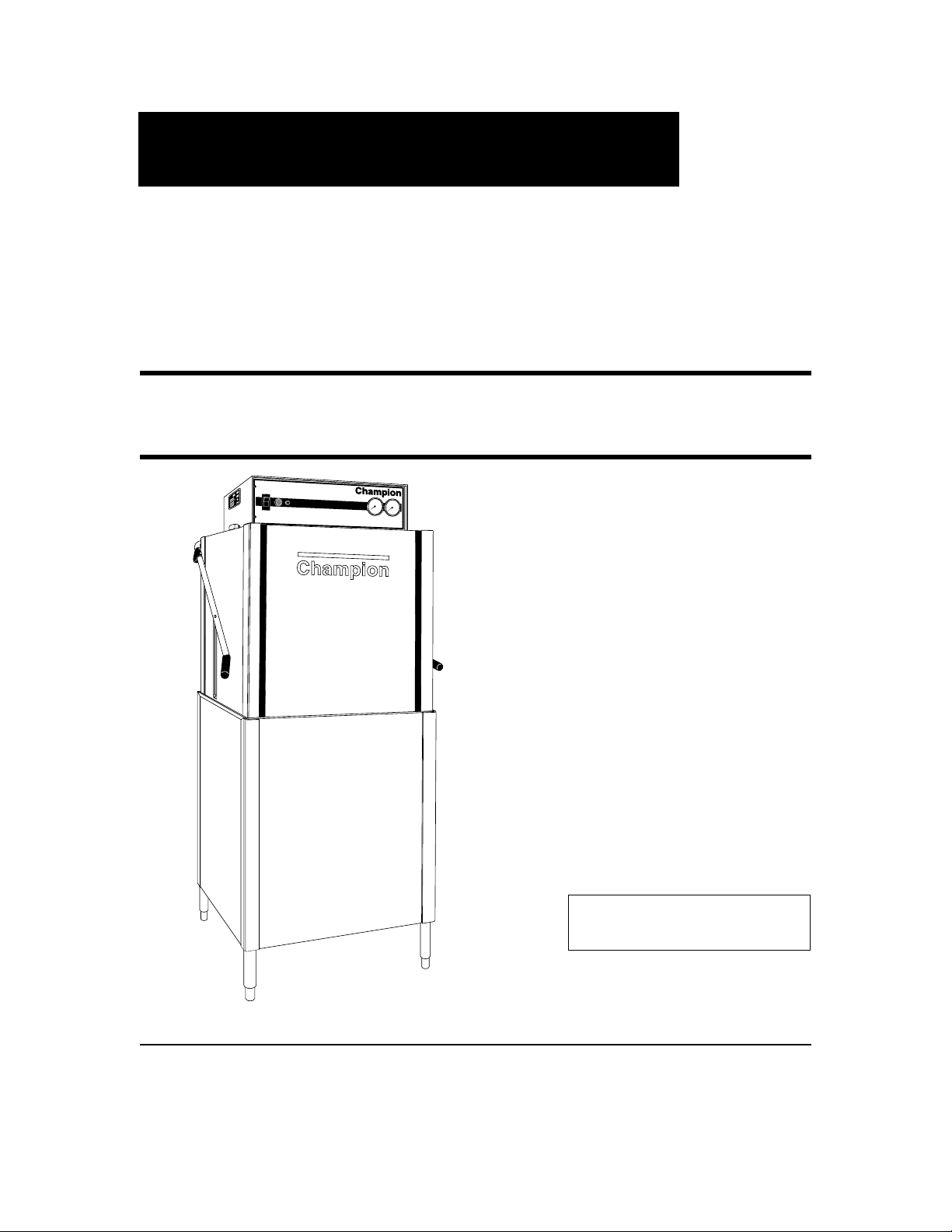
Door-Type
Dishwasher
Model
D-HB
High Temperature
with Built-in Booster
D-H1
High Temperature
D-LF
Low Temperature
April, 1996
P.O. Box 4149
Winston-Salem, North Carolina 27115-4149
336/661-1556 Fax: 336/661-1660
Email: champion@championindustries.com
Manual P/N 111807
Champion
Machine Serial No.
Champion Industries, Inc.
2674 N. Service Road
Jordan Station, Ontario, Canada L0R 1S0
905/562-4195 Fax: 905/562-4618
Page 2

Complete the information below so it will be available for quick reference.
Model Number
____________________________
Serial Number
_________________________
Voltage and Phase
_______________________________________________________________
Champion Parts Distributor
___________________________________
Phone
______________
______________________________________________________________________________
Champion Service Agency
____________________________________
Phone
______________
______________________________________________________________________________
Champion Industries Service: 1 (800) 858-4477 Champion Service Fax: 1 (336) 661-1660
In Canada:
Champion Service: 1 (800) 263-5798
Canada Service Fax: 1 (905) 562-4618
We strongly recommend that you fax your orders.
NOTE: When calling to order parts, be sure to have the model number, serial number, voltage,
and phase of your machine.
COPYRIGHT © 1996 by Champion Industries, Inc.
Machine Data Plate with
Model & Serial number
located on left side of
control cabinet.
Page 3

Revision History
Revision Revised Serial Number Comments
Date Pages Effectivity
4/16/96 — — Reissue manual with new replacement parts lists
9/16/96 11-12 — Revised straight-through to corner conversion
instructions
1
REVISIONS
Page 4

CONTENTS
Page
The Dishwashing Formula ............................................................................................................ 6
WARRANTY ................................................................................................................................ 7
INTRODUCTION......................................................................................................................... 8
GENERAL .................................................................................................................................... 9
Model Numbers ...................................................................................................................... 9
Standard Equipment................................................................................................................ 9
Options.................................................................................................................................... 9
Accessories ............................................................................................................................. 9
Electrical Power Requirements............................................................................................... 10
INSTALLATION........................................................................................................................... 11
Unpacking ............................................................................................................................... 11
Changing from Straight-through to Corner Operation ........................................................... 11
Electrical Connections ............................................................................................................ 12
Plumbing Connections............................................................................................................13
Water Connections .................................................................................................................. 13
Drain Connections .................................................................................................................. 14
Chemical Connections ............................................................................................................14
Model D-HB, D-H1 and D-LF......................................................................................... 15
Detergent................................................................................................................................. 15
Rinse Aid/Sanitizer ................................................................................................................. 16
INITIAL START-UP ..................................................................................................................... 18
Model D-HB, D-H1 and D-LF
OPERATION................................................................................................................................. 19
Model D-HB, D-H1 and D-LF
MAINTENANCE.......................................................................................................................... 20
Maintenance Schedule ............................................................................................................20
CLEANING...................................................................................................................... 20
Every 2 Hours or After Each Meal Period
Model D-HB, D-H1 and D-LF............................................................................ 20
Every 8 Hours or at the End of the Day
Model D-HB, D-H1 and D-LF............................................................................ 20
DELIMING ...................................................................................................................... 21
Deliming process
Model D-HB, D-H1 and D-LF............................................................................ 21
OPERATION CHECKS................................................................................................... 22
Daily...........................................................................................................................22
Weekly ....................................................................................................................... 22
2
CONTENTS
Page 5

CONTENTS
Page
TROUBLESHOOTING ................................................................................................................ 22
BASIC SERVICE .......................................................................................................................... 24
Electrical Service .................................................................................................................... 24
Fuses................................................................................................................................. 25
Motor Overloads............................................................................................................... 25
Timers............................................................................................................................... 26
Timed Fill/Low Water Tank Heat Protection................................................................... 27
Heater Element Wiring..................................................................................................... 28
Motor Connections........................................................................................................... 29
Mechanical Service................................................................................................................. 30
Pump Seal Replacement................................................................................................... 30
REPLACEMENT PARTS LIST.................................................................................................... 31
ELECTRICAL SCHEMATICS & DIAGRAMS .......................................................................... 67
LIST OF FIGURES
Figure 1 — Placement for Corner Operation.............................................................................. 11
Figure 2 — Changing the Track Assembly ................................................................................ 12
a — Straight-Through Configuration
b — Corner Configuration
Figure 3 — Drain Connection..................................................................................................... 14
Figure 4 — Chemical Connection Points ................................................................................... 15
Figure 5 — Detergent Probe Insertion Point .............................................................................. 15
Figure 6 — Rinse Aid Insertion Point ........................................................................................ 16
Figure 7 — Rinse Aid/Sanitizer Injection Points ....................................................................... 17
Figure 8 — Operator Controls .................................................................................................... 18
Figure 9 — Door Activated Drain Lever Assembly................................................................... 18
Figure 10 — Fuses ........................................................................................................................ 25
Figure 11 — Motor Overload ....................................................................................................... 25
Figure 12 — Cycle Timer ............................................................................................................. 26
Figure 13 — Cycle Timer Chart ................................................................................................... 26
Figure 14 — Fill Timer ................................................................................................................. 26
Figure 15 — Fill Timer Chart ....................................................................................................... 26
Figure 16 — Float Switch ............................................................................................................. 27
Figure 17 — Float Switch Troubleshooting Chart........................................................................ 27
Figure 18 — Pump Motor Wiring Diagrams ................................................................................ 29
Figure 19 — Pump Seal Replacement .......................................................................................... 30
Figure 20 — Doors, Panels and Gauges ....................................................................................... 32
Figure 21 — Door Handle Assembly and Springs ....................................................................... 34
Figure 22 — Door Linkage ........................................................................................................... 35
Figure 23 — Track Assembly, Float Switch and Drain Assembly............................................... 36
Figure 24 — Wash/Rinse Spray System Assembly (Beginning with S/N 11599 and above) ..... 38
3
CONTENTS
Page 6

LIST OF FIGURES (cont’d)
Figure 25 — Wash/Rinse Spray Arms (Beginning with S/N 77855 through S/N 11599) ........... 40
Figure 26 — Wash/Rinse Spray Arms (Prior to S/N 77854)........................................................ 42
Figure 27 — Tank Heater Element and Thermostat..................................................................... 44
Figure 28 — Fill Piping Assembly ............................................................................................... 46
Figure 29 — Fill Piping Assembly ............................................................................................... 48
Figure 30 — Pump Assembly ....................................................................................................... 50
Figure 31 — Electric Booster Assembly and Thermostat ............................................................ 52
Figure 32 — Control Cabinet........................................................................................................ 54
Figure 33 — Dishracks ................................................................................................................. 56
Figure 34 — Steam Coil/Steam Injector Fill Piping .................................................................... 60
Figure 35 — Steam Coil and Booster Assembly .......................................................................... 62
Figure 36 — Steam Injector and Booster Assembly .................................................................... 64
Figure 37 — Electrical Schematic D-HB/D-H1, 3 Phase............................................................. 68
Figure 38 — Wiring Diagram D-HB, 3 Phase.............................................................................. 69
Figure 39 — Electrical Schematic D-HB/D-H1/D-LF, 1 Phase................................................... 70
Figure 40 — Wiring Diagram D-HB, 1 Phase.............................................................................. 71
Figure 41 — Wiring Diagram D-H1/D-LF, 3 Phase..................................................................... 72
4
CONTENTS
Page 7

5
COMPONENT DIAGRAM
D-HB
COMPONENT DIAGRAM
PRESSURE
GAUGE
FINAL RINSE
FILL VALVE
PRESSURE REDUCING
VALVE
(PG. 47)
(PG. 47)
(PG. 33)
VACUUM
BREAKER
GREEN START
SWITCH
(PG. 47)
(PG. 55)
FILL
TIMER
CYCLE
TIMER
(PG. 55)
(PG. 55)
MACHINE ELECTRICAL
CONNECTION
DATA PLATE (PG. 12)
LINE STRAINER
WATER
CONNECTION (PG. 47)
ELECTRICAL
CONNECTION
CHEMICAL
ELECTRICAL
CONNECTIONS (PG. 15)
DOOR SAFETY
MAGNETIC REED
SWITCH (PG. 33)
POWER
SWITCH
DOOR
SPRINGS
(PG. 55)
(PG. 35)
WASH
PUMP
(PG. 12)
(PG. 51)
FLOAT SWITCH
HEAT
PROTECTION (PG. 37)
TEMPERATURE
GAUGES
INTERCHANGEABLE
WASH/RINSE
SPRAY ARMS
DRAIN
ASSEMBLY
DRAIN
CONNECTION
(PG. 37)
(PG. 33)
(PG. 39)
BOOSTER
HIGH LIMIT
THERMOSTAT (PG. 53)
WASH TANK
HEATER
(PG. 37)
(PG. 45)
FINAL RINSE
BOOSTER HEATER
(D-HB ONLY) (PG. 53)
BOOSTER TANK HEAT
THERMOSTAT
WASH TANK HEAT
THERMOSTAT
(PG. 53)
(PG. 45)
Page 8

6
The Dishwasher Formula
Five Elements for Cleaning Dishes
A Perfect Score means Clean Ware for your customers . . .
Peak Dishwasher Performance for you.
Point Value
1. Time ..................................................................................
20
Wash and rinse times (set by NSF and Champion) allow everything to work.
2. Temperature ......................................................................
20
Heated water penetrates and loosens soil on dishes.
3. Mechanical Action ............................................................ 20
Pumps produce water pressure which flushes the soil off dishes.
4. Chemical Action ............................................................... 20
Detergent breaks down grease and loosens soil particles.
5. Procedure..........................................................................
20
Pre-scraping and rinsing removes large food particles from the dishes.
Proper washroom ventilation and humidity shortens dish drying time.
SCORE 100
Page 9

7
WARRANTY
LIMITED WARRANTY
Champion Industries Inc. (herein referred to as Champion), P.O. Box 4149, Winston-Salem, North Carolina 27115,
and P.O. Box 301, 2674 N. Service Road, Jordan Station, Canada, L0R 1S0, warrants machines, and parts, as set out
below.
Warranty of Machines: Champion warrants all new machines of its manufacture bearing the name “Champion”
and installed within the United States and Canada to be free from defects in material and workmanship for a
period of one (1) year after the date of installation or fifteen (15) months after the date of shipment by
Champion, whichever occurs first. [See below for special provisions relating to glasswashers.] The warranty
registration card must be returned to Champion within ten (10) days after installation. If warranty card is not
returned to Champion within such period, the warranty will expire after one year from the date of shipment.
Champion will not assume any responsibility for extra costs for installation in any area where there are
jurisdictional problems with local trades or unions.
If a defect in workmanship or material is found to exist within the warranty period, Champion, at its election,
will either repair or replace the defective machine or accept return of the machine for full credit; provided,
however, as to glasswashers, Champion’s obligation with respect to labor associated with any repairs shall end
(a) 120 days after shipment, or (b) 90 days after installation, whichever occurs first. In the event that Champion
elects to repair, the labor and work to be performed in connection with the warranty shall be done during regular
working hours by a Champion authorized service technician. Defective parts become the property of Champion.
Use of replacement parts not authorized by Champion will relieve Champion of all further liability in connection
with its warranty. In no event will Champion’s warranty obligation exceed Champion’s charge for the machine.
The following are not covered by Champion’s warranty:
a. Lighting of gas pilots or burners.
b. Cleaning of gas lines.
c. Replacement of fuses or resetting of overload breakers.
d. Adjustment of thermostats.
e. Adjustment of clutches.
f. Opening or closing of utility supply valves or switching of electrical supply current.
g. Cleaning of valves, strainers, screens, nozzles, or spray pipes.
h. Performance of regular maintenance and cleaning as outlined in operator’s guide.
i. Damages resulting from water conditions, accidents, alterations, improper use, abuse,
tampering, improper installation, or failure to follow maintenance and operation procedures.
j. Wear on Pulper cutter blocks, pulse vanes, and auger brush.
Examples of the defects not covered by warranty include, but are not limited to: (1) Damage to the exterior or
interior finish as a result of the above. (2) Use with utility service other than that designated on the rating plate.
(3) Improper connection to utility service. (4) Inadequate or excessive water pressure. (5) Corrosion from chemicals dispensed in excess of recommended concentrations. (6) Failure of electrical components due to connection
of chemical dispensing equipment installed by others. (7) Leaks or damage resulting from such leaks caused by
the installer, including those at machine table connections or by connection of chemical dispensing equipment
installed by others. (8) Failure to comply with local building codes. (9) Damage caused by labor dispute.
Warranty of Parts: Champion warrants all new machine parts produced or authorized by Champion to be free
from defects in material and workmanship for a period of 90 days from date of invoice. If any defect in
material and workmanship is found to exist within the warranty period Champion will replace the defective
part without charge.
DISCLAIMER OF WARRANTIES AND LIMITATIONS OF LIABILITY
. CHAMPION’S WARRANTY
IS ONLY TO THE EXTENT REFLECTED ABOVE. CHAMPION MAKES NO OTHER WARRANTIES,
EXPRESS OR IMPLIED, INCLUDING, BUT NOT LIMITED, TO ANY WARRANTY OF
MERCHANTABILITY, OR FITNESS OF PURPOSE. CHAMPION SHALL NOT BE LIABLE FOR
INCIDENTAL OR CONSEQUENTIAL DAMAGES. THE REMEDIES SET OUT ABOVE ARE THE
EXCLUSIVE REMEDIES FOR ANY DEFECTS FOUND TO EXIST IN CHAMPION DISHWASHING
MACHINES AND CHAMPION PARTS, AND ALL OTHER REMEDIES ARE EXCLUDED, INCLUDING
ANY LIABILITY FOR INCIDENTALS OR CONSEQUENTIAL DAMAGES.
Champion does not authorize any other person, including persons who deal in Champion dishwashing machines to
Page 10

INTRODUCTION
Welcome to Champion . . .
and thank you for allowing us to take care of your dishwashing needs.
This manual covers the door-type series dishwasher models D-H1, D-HB, and D-LF.
Your machine was completely assembled, inspected, and thoroughly tested at our factory before
it was shipped to your installation site.
This manual contains:
• Warranty Information
• Operation and Cleaning Instructions
• Maintenance Instructions
• Troubleshooting Guide
• Basic Service Information
• Replacement Parts Lists
• Electrical Schematics
Complete and return your warranty registration card within ten (10) days after the installation of
your machine.
All information, illustrations and specifications contained in this manual are based upon the
latest product information available at the time of publication. Champion constantly improves
its products and reserves the right to make changes at any time or to change specifications or
design without notice and without incurring obligation.
For your protection, factory authorized parts should always be used for repairs.
Replacement parts may be ordered from your Champion authorized parts distributor or
from your Champion authorized service agency. When ordering parts, please supply the model
number, serial number, voltage and phase of your machine, the part number, part description and
quantity.
8
INTRODUCTION
Page 11

GENERAL
This manual covers the Champion door type dishwashing machine. These machines are fully
automatic and come equipped with a 1-HP pump motor.
The D-series dishwasher is available in the following models:
Model Numbers
D-H1, D-HB, D-LF
The D-H1 model is a high temperature (180°F/82°C rinse) sanitizing model without booster.
The D-HB model is a high temperature (180°F/82°C rinse) sanitizing model with booster.
The D-LF is a low temperature (Min. 120°F/49°C-140°F/60°C Optimum) sanitizing model for
use with a sodium hypochlorite (Chlorine) based sanitizer at a minimum concentration of
50PPM in the final rinse.
Standard Equipment includes:
D-H1, D-HB, D-LF
• Automatic tank fill • Common utility connections
• Built-in electric or steam booster heater • Two dish racks (peg and flat bottom)
(D-HB only) • Detergent/chemical connection provisions
• Door activated drain • Stainless steel front and side panels
• Field convertible to corner model • Top-mounted, splash-proof control console
• Electric tank heat • 60-second time cycle
• Balanced three door lift system • 1-1/2" O.D. gravity drain connection
• Low-water tank heat protection • Water pressure regulating valve
• 1-hp drip-proof pump motor (mounted) (D-HB only)
• Door safety switches • Interchangeable upper and lower spray arms
Options (D-HB only)
• Electric booster (70°F/39°C temperature rise)
heater for 110°F/43°C supply water
• Steam injector or steam coil tank heat
(steam booster 40°F/23°C – 70°F/39°C rise)
• Single source gas booster system
Accessories
Additional dishracks:
Dish rack (peg) P/N 101285
Silverware rack (flat bottom) P/N 101273
9
GENERAL
Page 12

Electrical Power Requirements
Model Voltage Booster Rise Machine Power Requirement
(D-HB Only) Full Load Amps (125% Service Factor)
D-H1/LF 115/60/1 — 48 Amps 60 Amps
D-H1/LF 208/60/1 — 23 Amps 29 Amps
D-H1/LF 220/60/1 — 23 Amps 29 Amps
D-H1/LF 230/60/1 — 23 Amps 29 Amps
D-H1/LF 240/60/1 — 24 Amps 30 Amps
D-H1/LF 208/60/3 — 12 Amps 15 Amps
D-H1/LF 220/60/3 — 13 Amps 16 Amps
D-H1/LF 230/60/3 — 13 Amps 16 Amps
D-H1/LF 240/60/3 — 13 Amps 16 Amps
D-H1/LF 380/60/3 — 7 Amps 9 Amps
D-H1/LF 415/60/3 — 8 Amps 10 Amps
D-H1/LF 480/60/3 — 6 Amps 8 Amps
D-H1/LF 575/60/3 — 5 Amps 6 Amps
D-HB 115/60/1 — — —
D-HB 208/60/1 40°F/23°C 59 Amps 74 Amps
D-HB 220/60/1 40°F/23°C 61 Amps 76 Amps
D-HB 230/60/1 40°F/23°C 63 Amps 79 Amps
D-HB 240/60/1 40°F/23°C 65 Amps 81 Amps
D-HB 208/60/3 40°F/23°C 33 Amps 41 Amps
D-HB 220/60/3 40°F/23°C 35 Amps 44 Amps
D-HB 230/60/3 40°F/23°C 36 Amps 45 Amps
D-HB 240/60/3 40°F/23°C 37 Amps 46 Amps
D-HB 380/60/3 40°F/23°C 20 Amps 25 Amps
D-HB 415/60/3 40°F/23°C 20 Amps 25 Amps
D-HB 480/60/3 40°F/23°C 17 Amps 21 Amps
D-HB 575/60/3 40°F/23°C 14 Amps 18 Amps
D-HB 115/60/1 — — —
D-HB 208/60/1 — — —
D-HB 220/60/1 — — —
D-HB 230/60/1 — — —
D-HB 240/60/1 — — —
D-HB 208/60/3 70°F/39°C 50 Amps 63 Amps
D-HB 220/60/3 70°F/39°C 52 Amps 65 Amps
D-HB 230/60/3 70°F/39°C 54 Amps 68 Amps
D-HB 240/60/3 70°F/39°C 56 Amps 70 Amps
D-HB 380/60/3 70°F/39°C 30 Amps 38 Amps
D-HB 415/60/3 70°F/39°C 33 Amps 41 Amps
D-HB 480/60/3 70°F/39°C 28 Amps 35 Amps
D-HB 575/60/3 70°F/39°C 23 Amps 29 Amps
10
GENERAL
Page 13
INSTALLATION
Unpacking
CAUTION:
Care should be taken when lifting the machine to prevent damage.
1. Immediately after unpacking the machine, inspect for any shipping damage.
If damage is found, save the packing material and contact the carrier immediately.
2. Remove the dishwasher from the skid. Adjust the feet if required, then move the
machine to its permanent location.
3. Level the machine (if required) by placing a level on the top of machine and adjusting
the feet. Level the machine front-to-back and side-to-side.
4. Remove the two dishracks from the interior of the machine.
NOTE:
The installation of your machine must meet local health codes.
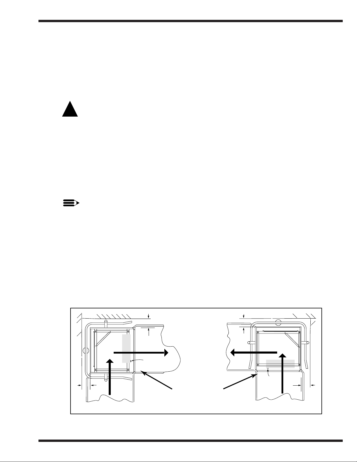
Changing from Straight-through to Corner Operation
Your door-type dishwasher is shipped from the factory in a straight-through configuration.
The following instructions explain how to convert your machine for corner operation.
Refer to Fig. 1 below.
1. Place the dishwasher so the operator controls are readily accessible.
2. Minimum clearance from any corner wall is 5-1/4" (133mm).
11
INSTALLATION
!
Figure 1
Placement for Corner Operation
Note:
Power switch is
readily accessible.
Do not place the dishwasher closer than 5-1/4" (133mm) to any wall.
5-1/4"[133mm] MIN.
5-1/4"[133mm] MIN.
W
A
LL
WALL
FRONT
POWER ON
SWITCH
5-1/4"[133mm] MIN.
5-1/4"[133mm] MIN.
W
A
LL
WALL
FRONT
POWER ON
SWITCH
Page 14
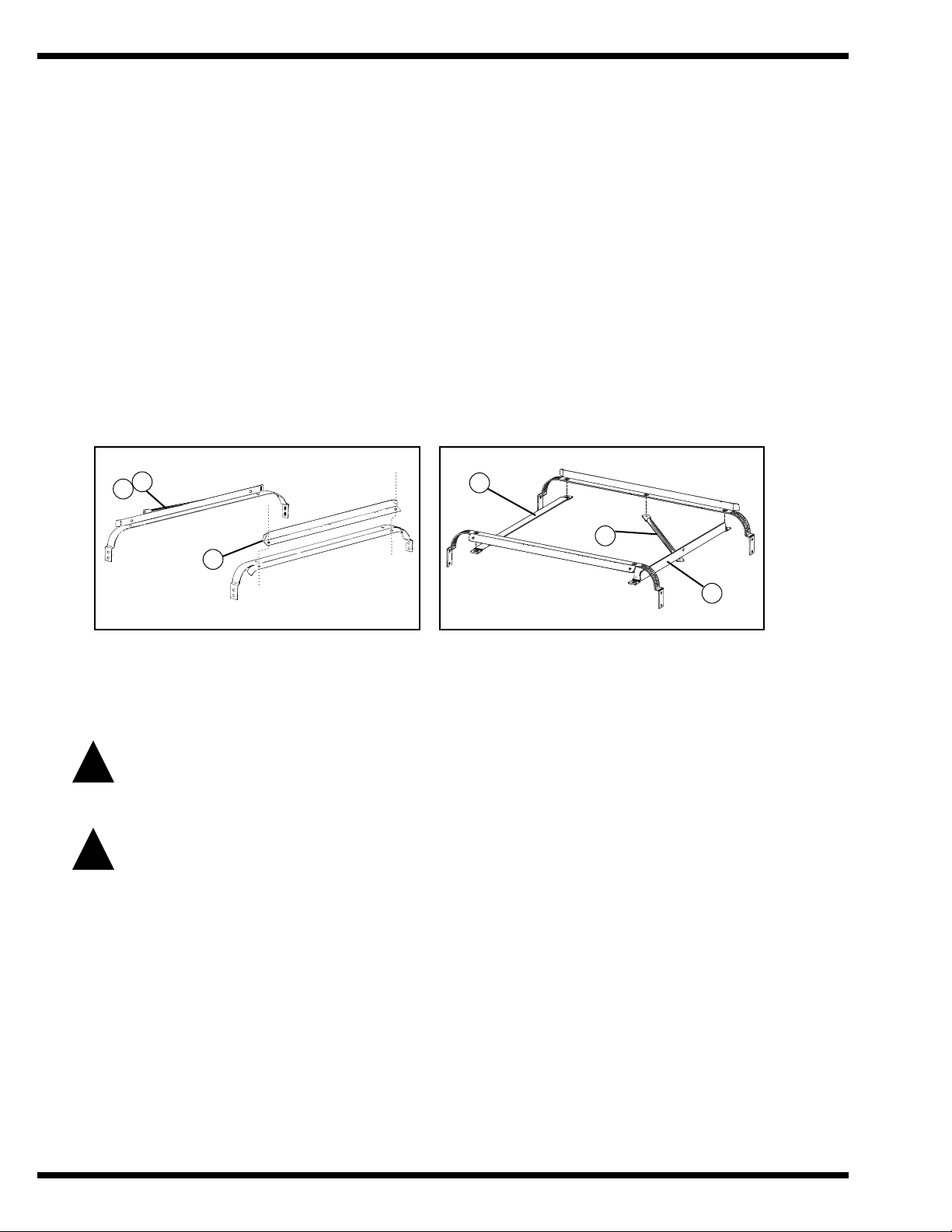
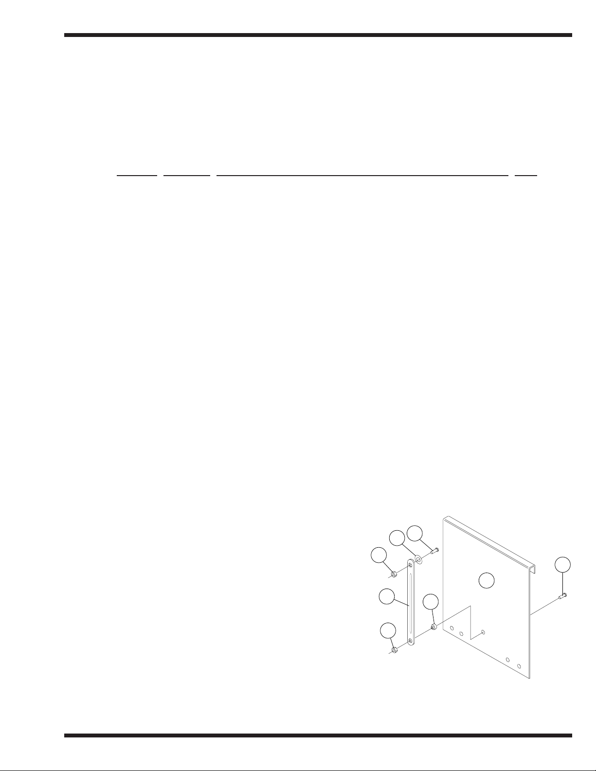
Changing from Straight-through to Corner Operation (cont’d)
Refer to Fig. 2 and perform the steps below.
1. Remove the front rack guide (A). Discard the square spacers.
2. Move front rack guide (A) to the left side of the rack tracks. (See Fig. 2b) Use existing
hardware.
3. Unbolt the track (B) and rack support rod (C).
4. Remove and save the two remaining fasteners from rear track.
5. Bolt (B) and (C) as shown in Fig. 2b.
Electrical Connections
WARNING:
Electrical and grounding connections must comply with the National Electrical Code
and/or Local Electrical Codes.
WARNING:
When working on the dishwasher, disconnect the electric service and place a tag at the
disconnect switch to indicate work is being done on that circuit.
1. A qualified electrician must compare the electrical power supply with the machine
electrical specifications stamped on the MACHINE ELECTRICAL CONNECTION
PLATE located inside the top mounted control cabinet before connecting to the incoming
service at a fused disconnect switch.
2. Motor rotation was set at the factory. Check the rotation of the motor shaft (CW when
viewed from rear of motor). For three phase machines, reversing the motor direction is
done in the control cabinet by reversing the wires L1 and L2 on the disconnect side of the
main electrical connection block. For single phase machines, motor rotation is changed at
the motor connection plate on the rear of the single phase motor.
12
INSTALLATION
!
!
Figure 2a
Straight-Through Configuration
Figure 2b
Corner Configuration
A
B
C
A
B
C
Figure 2
Changing the Track Assembly
Page 15

Electrical Connections (cont’d)
3. A knock-out is provided at the rear of the top mounted control cabinet for the electrical
service connection. A single source electrical connection has been provided. A fused
disconnect switch or circuit breaker (supplied by others) is required to protect each power
supply circuit.
Plumbing Connections
CAUTION:
Plumbing connections must comply with local sanitary and plumbing codes.
Water Connections
1. Connect the hot water supply to the “Y” strainer or pressure reducing valve (PRV) at the
final rinse piping (located behind the control cabinet at the top of the machine).
2. Minimum incoming water supply temperature requirements are listed below:
D-HB with built-in 40°F/23°C rise electric booster (Minimum 140°F/60°C)
(Min./Max. flow pressure 20-22 psi/138 Kpa)
D-HB with built-in 70°F/39°C rise electric booster (Minimum 110°F/43°C)
(Min./Max. flow pressure 20-22 psi/138 Kpa)
D-H1 without built-in booster (Minimum 180°F/70°C)
(Min./Max. flow pressure 20-22 psi/138 Kpa)
D-LF (Minimum 120°F/49°C - 140°F/60°C Optimum)
(Min./Max. flow pressure 20-22 psi/138 Kpa)
3. A manual shut-off valve for steam and water (supplied by others) should be installed in
supply line to allow for servicing of the machine. The shut-off valve should be the same
size or larger than the supply line.
4. A 3/4" Pressure Regulating Valve (PRV), should be installed on the incoming water supply
line if water flow pressure exceeds 20-22 psi/138 Kpa.
A PRV is standard equipment on Model D-HB.
A PRV is not standard equipment on Models D-H1 and D-LF.
The PRV may be obtained locally or direct from Champion.
13
INSTALLATION
!
Page 16

Drain Connections
Refer to Fig. 3 for the location of the machine drain.
1. Models D-HB, D-H1, and D-LF are GRAVITY DRAIN machines equipped
with a 1-1/2" hose connection point.
• Drain height for ALL MODELS must not exceed 15" above floor level.
WARNING:
Connection of the machine to a drain line higher than the machine drain height
will prevent the machine from draining properly.
Ventilation
NOTE:
Ventilation must comply with local sanitary and plumbing codes.
CAUTION:
Exhaust air should not be vented into a wall, ceiling, or concealed space of a building.
Condensation can cause damage.
14
INSTALLATION
!
Figure 3
D-HB, D-H1, D-LF
1-1/2" Drain Connection
Front Left Side of Machine
1-1/2" Drain Connection
!
Page 17
Chemical Connections
NOTE:
Consult a qualified chemical supplier for your chemical needs.
Models D-HB, D-H1 and D-LF
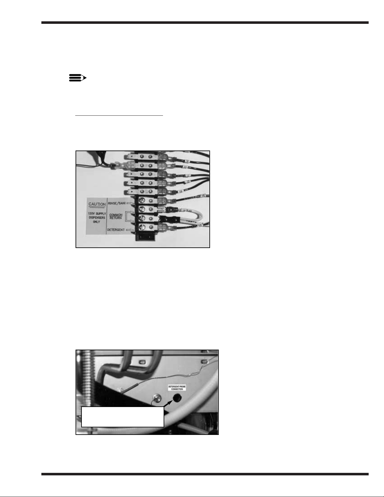
1. Refer to Fig. 4
Labeled chemical signal connection points are provided inside the
control cabinet for chemical dispensing equipment (supplied by others).
Detergent
1. Refer to Fig. 5
A removable black plug, located on the rear of the wash tank is provided as a detergent
probe insertion point.
15
INSTALLATION
Figure 4
D-HB, D-H1, D-LF
Chemical Connection Points
Left Side Interior of Control Cabinet
Signal connection points include:
• Detergent signal 120VAC
between Wire #10 and Wire #2
(1 AMP MAX AMP LOAD)
• Rinse Aid/Sanitizer signal 120VAC
between Wire #15 and Wire #2
(1 AMP MAX AMP LOAD)
1/2" Black Removable Plug
Detergent Probe Insertion Point
Figure 5
D-HB, D-H1, D-LF
Detergent Probe Insertion Point
Wash Tank (Rear)
Page 18

Chemical Connections (cont’d)
Detergent (cont’d)
2. Detergent may be added manually if dishwasher is not equipped with dispensing
equipment. Consult your chemical supplier for recommended amounts.
Rinse Aid/Sanitizer
Model D-HB and D-H1
Refer to Fig. 6
1. A rinse aid injection point is provided via a 1/8" NPT plug located in the final rinse piping.
The plug is located in a Tee fitting on the outlet side of the vacuum breaker. The vacuum
breaker is located behind the control cabinet at the top of the machine.
2. Use a liquid rinse aid.
NOTE:
Models D-HB and D-H1 do not require sanitizer.
16
INSTALLATION
Figure 6
Rinse aid Insertion Point
D-HB, D-H1 Only
1/8" NPT plug
Rinse aid Injection Point
Page 19

Chemical Connections (cont’d)
Rinse Aid/Sanitizer (cont’d)
Model D-LF
Refer to Fig. 7
1. A Rinse aid injection point is provided via a 1/8" NPT plug located in the final rinse
piping. The plug is located in a Tee fitting on the outlet side of the vacuum breaker. The
vacuum breaker is located behind the control cabinet at the top of the machine.
2. Use a liquid rinse aid.
3. A Sanitizer injection point is provided via a 1/4" NPT plug located in the final rinse piping.
The plug is located in a Tee fitting on the outlet side of the vacuum breaker. The vacuum
breaker is located behind the control cabinet at the top of the machine.
4. Use a sodium hypochlorite (Chlorine) based sanitizer at a minimum concentration of
50PPM in the final rinse.
Use chlorine test papers to verify and monitor the 50PPM chlorine level.
WARNING:
Never premix rinse aid with the sanitizing agent. Mixing may cause hazardous gases to form.
CAUTION:
Some metal, including silver, aluminum, and pewter are attacked by sodium hypochlorite
(chlorine sanitizer). Avoid cleaning these metals in a D-LF dishwasher.
17
INSTALLATION
Figure 7
D-LF
Rinse Aid/Sanitizer Injection Points
1/4" NPT plug
Sanitizer injection point
1/8" NPT plug
Rinse aid injection point
!
!
Page 20

INITIAL START-UP
After plumbing and electrical connections are completed, follow the steps below to place your
machine in service.
Model D-HB, D-H1 and D-LF
Refer to Figs. 8 and 9 below.
1. Remove any foreign material from inside the machine. Make sure scrap screens are
in place.
2. Make sure drain lever assembly is closed.
3. Close the Door.
4. Turn the water and main power sources to the dishwasher ON.
5. Flip the Power switch to the ON position. The “power on” light will illuminate and the
machine will automatically fill with water.
6. Check the machine for leaks.
7. Push the Green Start Button to check automatic cycle.
8. Check pump motor rotation. Rotation is CW when viewed from rear of motor.
9. If machine checks okay, lift the drain lever assembly to drain machine.
10. Flip the power switch to OFF.
18
INITIAL START-UP
Figure 8
Operator Controls
Top Mounted Control Cabinet
Figure 9
Door Activated
Drain Lever Assembly
Main power switch
circuit breaker
Green pushbutton
start switch
Green in cycle lite
Pressure gauge
Drain lever assembly
Temperature Gauges
Page 21

OPERATION
Model D-HB, D-H1 and D-LF
1. Close the door and flip power switch ON Power light illuminates. Tank fills
automatically and tank heat comes on.
2. Monitor wash tank temperature gauge Wait for temperature reading to reach
Min. 150°F/66°C (D-HB, D-H1 Only)
Temperature reading must be
Min. 120°F-140°F/49°C-60°C Optimum
(For D-LF Only)
3. Prescrap and load ware into rack Place dishes edgewise in peg rack, cups
and bowls upside down in flat rack, and
silverware spread evenly in single layer in
flat rack.
4. Open door, insert rack
5. Close door, Push Green start button Green cycle light will illuminate. Automatic
cycle begins.
Machine washes for 45 sec., then pauses for
1 sec.
6. During Final Rinse monitor pressure Machine final rinses for 14 sec. Pressure
gauge and final rinse temperature gauge reading must read between 20-22 PSI.
gauge Temperature gauge must read
180-195°F/82-91°C (D-HB, D-H1 Only)
Min. 120°-140°F/49°C-60°C Optimum
(D-LF Only)
7. 60-second cycle complete Green cycle light goes out.
8. Open door, remove clean rack Insert another rack of soiled ware.
9. After each meal period or every two Lift drain lever assembly to drain
hours operation machine. Flush interior and clean scrap
screens and pump intake strainer. Check
spray arms and clean if necessary.
NOTE:
Opening the door at any time during the cycle will stop the machine.
Closing the door and pushing the Green start button will resume the cycle where it left off.
19
OPERATION
Page 22

MAINTENANCE
Cleaning your machine is the best maintenance that you can provide. Components that are not
regularly flushed and cleaned do not perform well.
The Maintenance intervals shown in the following schedules are the minimum requirements
necessary for the proper performance of your machine. Maintenance intervals should be
shortened whenever your machine is faced with abnormal working conditions, hard water, or
multiple shift operations.
Maintenance Schedule
CLEANING
• Every 2 Hours or After Each Meal Period
Model D-HB, D-H1, and D-LF
1. Flip the power switch OFF.
2. Lift drain lever, drain the machine.
3. Flush tank interior with fresh water.
4. Remove and clean the scrap screens. Clean the pump intake screen.
5. Inspect the spray arm nozzles and rinse nozzles. Clean if necessary.
6. Close door, flip power switch ON to refill machine.
• Every 8 Hours or at the End of the Day
Model D-HB, D-H1, and D-LF
1. Flip the power switch OFF.
2. Lift drain lever, drain the machine.
3. Flush tank interior with fresh water.
4. Remove and clean the scrap screens. Clean the pump intake screen.
5. Remove the spray arms.
6. Clean and inspect the spray arm bearings.
7. Flush the wash arm and rinse arm assemblies and nozzles.
8. Back flush the scrap screens and pump intake strainer.
9. Thoroughly clean the exterior of the machine. DO NOT HOSE DOWN WITH WATER.
10. Reassemble the machine. Leave the door open to aid overnight drying.
CAUTION:
DO NOT LEAVE WATER IN WASH TANK OVERNIGHT
20
MAINTENANCE
!
Page 23
DELIMING
Your dishwasher should be delimed regularly depending on the mineral content of your water.
Inspect the machine interior for mineral deposits and use a deliming solution for the best
cleaning results.
NOTE:
Consult your chemical supplier for an appropriate deliming solution.
WARNING:
Deliming solutions or other acids must not come in contact with household bleach
(sodium hypochlorite) or any chemicals containing chlorine, iodine, bromine, or fluorine.
Mixing will cause hazardous gases to form.
Skin contact with deliming solutions can cause severe irritation and possible chemical
burns. Consult your chemical supplier for specific safety precautions.
DELIMING PROCESS
Model D-HB, D-H1, and D-LF
1. Remove all dishes from machine.
2. Remove any chemical pick-up tubes from their containers.
3. Place each tube in a container of fresh water and prime the chemical lines for several
minutes to thoroughly flush chemical from the lines. Leave pick-up tubes out of their
containers.
4. Drain the machine and refill with fresh water.
5. Spray interior walls with delimimg solution and let sit for 5 or 10 minutes depending on
amount of build-up. Add deliming solution to wash tank. Do not let chemicals sit for longer
than 15 minutes.
6. Push the Green start button and run an automatic cycle.
7. Repeat Steps 3-4 if necessary.
8. Lift the drain lever assembly and drain the machine.
9. Refill the machine and run a complete cycle two additional times. Drain and refill the
machine after each cycle to thoroughly flush any deliming solution from the interior of
the machine.
10. Flip the power switch to OFF.
11. Drain machine.
12. Deliming is complete.
21
MAINTENANCE
!
Page 24

OPERATION CHECKS
• Daily
1. Check temperature gauges for proper readings.
2. Check pressure gauge for proper reading (D-H1, D-HB ONLY).
3. Check for leaks.
4. Check chemical supplies and refill as necessary.
• Weekly
1. Inspect all water lines for leaks.
2. Clean all detergent residue from the exterior of the machine.
3. Check the drains for leaks.
4. Clean accumulated mineral deposits from the tank heating elements
5. Check that float switch moves freely.
TROUBLESHOOTING
Before determining any specific cause of a breakdown or abnormal operation on your
dishwasher, check that:
Checklist
1. Main power and water supply are turned on to the machine
2. All switches are ON
3. Drain and overflow tube are in place and seated
4. Wash pipe and rinse nozzles are clean
5. Scrap screen(s) are properly positioned
6. Spray pipes are in their proper positions
7. Doors are fully closed
8. Thermostat(s) are at their correct setting
9. Sanitizer, detergent, and rinse additive dispensers are adequately filled.
If a problem still exists, use the following for troubleshooting.
CONDITION CAUSE SOLUTION
Machine will not start Door not closed ...................................Make sure doors are fully closed
Door safety switch faulty ....................Contact your service agency
Start switch faulty ...............................Contact your service agency
Main switch OFF ................................Check disconnect
Overload protector tripped ..................Reset overload in Control Box
Low or no water Main water supply is turned off..........Turn on house water supply
Drain/overflow tube is not
in place and seated ..........................Place and seat drain tube
Defective drain/overflow O’ring.........Replace O’ring
Machine doors not fully closed...........Close doors securely
Faulty fill valve ...................................Contact your service agency
Defective fill timer ..............................Replace fill timer
Stuck or defective float .......................Check floats and clean
Clogged “Y” strainer...........................Clean or replace
Continuous water filling Stuck or defective float .......................Check floats and clean
Defective drain/overflow O’ring.........Replace O’ring
Fill valve will not close.......................Clean or replace
Defective fill timer ..............................Replace fill timer
Drain tube not in place........................Look for drain tube in tank
22
MAINTENANCE
Page 25

CONDITION CAUSE SOLUTION
Any motor not running Overload protector tripped ..................Reset overload in Control Box
Defective motor...................................Contact your service agency
Wash tank water temperature Incoming water temperature
is low when in use at machine too low ..........................Raise temperature to:
140°F/60°C for D-HB and D-LF,
180°F/82°C for D-H1
Defective thermometer........................Check or replace
Defective thermostat ...........................Check for proper setting or replace
Lime scale buildup
on heating elements.........................Delime element
Defective heater element.....................Check or replace
Low steam pressure.............................Check steam supply pressure (15-30 psi)
Defective steam trap............................Check or replace
Defective solenoid valve.....................Check or replace
Insufficient pumped spray Clogged pump intake screen ...............Clean
pressure Clogged spray pipe..............................Clean
Scrap screen full..................................Must be kept clean and in place
Low water level in tank ......................Check drain and overflow tube
Pump motor rotation incorrect ............Reverse connection between L1 and L2
in Control Cabinet (3PH machines only)
Defective pump seal............................Contact Service Agent
Insufficient final rinse or no Faulty pressure reducing valve ...........Clean or replace
final rinse Improper setting on pressure
reducing valve .................................Set psi flow pressure at 20-22 psi/138 Kpa
Clogged rinse nozzle and/or pipe........Clean
Improper water line size......................Have installer change to proper size (3/4" min.)
Clogged “Y” strainer...........................Clean or replace
Low final rinse temperature Low incoming water temperature .......Check house supply water temperature
Improper setting of booster
thermostat........................................Be sure booster thermostat is set to maintain
180°F/82°C temperature
Defective booster thermostat ..............Replace thermostat
Defective thermometer........................Check for proper setting or replace
Poor washing results Detergent dispenser not
operating properly ...........................Contact detergent supplier
Insufficient detergents.........................Contact detergent supplier
Wash water temperature
too low.............................................See condition “Wash Tank Water Temperature”
above
Wash arm clogged...............................Clean
Improperly scraped dishes ..................Check scraping procedures
Ware being improperly placed
in rack..............................................Use proper racks. Do not overload racks
Improperly cleaned equipment............Unclog wash sprays and rinse nozzles to
maintain proper pressure and flow conditions.
Overflows must be open. Keep wash water
as clean as possible.
Electric Elements or steam
coils has soil/lime buildup ..............Clean and/or delime
Poor drying results Insufficient rinse-aid ...........................Contact chemical supplier
Low final rinse temp ...........................See condition “Low final rinse temperature.”
23
TROUBLESHOOTING
Page 26

24
BASIC SERVICE
BASIC SERVICE
This Basic Service section does not cover all possible repair procedures. If you require additional
service support, you may call your local service company or:
Champion National Service
1-800-858-4477
In Canada
1-800-263-5798
Please have the Model and Serial Number of the machine ready when you call.
ELECTRICAL SERVICE
NOTE:
DO NOT USE CHASSIS GROUND WHEN PERFORMING VOLTAGE CHECKS.
Doing so will result in false and inaccurate readings.
PERFORM VOLTAGE CHECKS BY READING FROM THE HOT SIDE OF THE
LINE AND NEUTRAL (any #2 or white wire).
WARNING:
USE EXTREME CAUTION when performing tests on energized circuits.
WARNING:
When repairing a circuit, disconnect the power at the main service disconnect switch and
place a tag at the disconnect switch to indicate that work is being performed on the circuit.
Troubleshooting
Schematics
Champion places an electrical schematic in the control cabinet of every machine before it is
shipped. Schematics are included at the back of this manual as well. Be aware that these
schematics include options that may not apply to your machine. Options are enclosed in dashed
lines with the words (IF USED) next to them on the schematic. Disregard any options that
appear on the schematics which are not a part of your machine.
Tools
All electrical repairs can be made with: Standard set of hand tools
Volt/Ohm Meter (VOM)
Clip-on AC current tester
Circuit Tests
Use a clip-on AC current tester to check the motors and electric heaters.
Use a VOM to test line voltages and the 120VAC and the 24VAC control circuits.
!
!
Page 27

25
BASIC SERVICE
ELECTRICAL SERVICE (cont’d)
Fuses
—
Refer to Fig. 10.
There are two fuse blocks, located in the center of
the main control cabinet. The (A) fuses protect the
main control transformer. The (B) fuses protect the
wash tank heater circuit.
Fuses are marked FU on the electrical schematic.
Booster heater circuits (D-HB only) are not fused.
To Replace a fuse:
Turn the dishwasher main power switch off.
Disconnect power to the machine at the main service disconnect switch.
Replace the fuse. If the fuse blows again,
DO NOT INCREASE THE FUSE SIZE.
DETERMINE THE CAUSE OF THE OVERLOAD.
Motor Overloads —
The wash pump motor has an overload to protect it from line voltage electrical overloads. The
overload disconnects 120VAC power to the motor contactor coil.
Refer to Fig. 11.
Note the Switch Lever on the Overload.
If the switch lever is off with the “0” showing
then the overload has tripped.
To Reset the Motor Overload:
Flip the overload switch to the On position.
A “1” should be visible on the switch lever.
To Replace a Motor Overload:
Disconnect the wires to the overload.
Release the mounting catch on the front
side of the overload. Push forward and lift out.
Snap the new overload into place and reconnect
the wires.
To adjust the overload setting:
The screwdriver in Fig. 11 is positioned
to adjust the motor overload AMP setting.
Read the full load amps (FLA) motor amps on the motor
nameplate. Adjust the overload dial to 125% of the nameplate
FLA or the maximum setting.
ELECTRICAL SERVICE (cont’d)
Timers
Figure 11
Motor Overload
Figure 10
Fuses
(Three phase shown)
A
B
Switch Lever
Page 28

D-HB, D-H1, and D-LF models have two timers
located in the top mounted main control cabinet.
These timers are not adjustable.
The timer chart is shown in Fig. 13.
Cycle Timer —
Refer to Fig. 12.
The cycle timer controls the dishwasher’s 60-second
operation. The timer consists of a timer motor, four
micro-switches, and four non-adjustable metal cams.
Cam A controls power to the timer motor
Cam B controls power to the wash motor.
Cam C controls power to the final rinse valve.
Cam D controls the dishwasher instant start.
Fill Timer —
Refer to Fig. 14.
The fill timer controls the dishwasher’s 90-second fill operation.
The timer consists of a timer motor, one micro-switch, and one
non-adjustable plastic cam. The fill timer operates during initial fill
and any time the low water tank heat protection circuit calls for
make-up water. Refer to Timed Fill/Low Water Tank Heat Protection
on the next page for an explanation of the fill timer operation.
ELECTRICAL SERVICE (cont’d)
Timed Fill/Low Water Tank Heat Protection —
26
BASIC SERVICE
Figure 14
Fill Timer
Figure 12
Cycle Timer
Figure 13
Cycle Timer Chart
A
B
C
D
Figure 15
Fill Timer Chart
10
52015 253530 40 50
TIMER CYCLE 60-SEC.
8
WASH 45-SEC.
DWELL 1-SEC.
RINSE 14-SEC.
8 53
INSTANT START 45-SEC.
CAM
TIMER
CAM
WASH
CAM
RINSE
CAM
INSTANT
START
A
B
C
D
SECOND
NOTRA
NC
NO
TRB
NC
NOTRC
NC
NO
TRD
NC
0
1
45
45
47
55 60
2
NCN
COM.
TIMER
SWITCH
DETAIL
3
O
1
FILL TIME 90-SEC.
FILL TIMER
Page 29

Models D-HB, D-H1, and D-LF use a float switch and fill timer to control
tank fill and tank heat.
For Model D-HB only, the built-in booster heat circuit is also controlled
by the float switch.
Operation:
1. When dishwasher main power switch is turned on, fill timer runs for
a minimum of 90 seconds to fill the tank.
2. The float switch ball rises; its normally open contacts close. The fill
circuit times out; the fill solenoid de-energizes, and the tank heat and
booster heat energize.
3. If water level drops below the float level, the float switch ball moves
down; heat de-energizes. The fill solenoid energizes and the fill timer
runs for a minimum of 90 seconds to refill the tank.
4. If the tank is not full of water at the end of the 90-second fill timer
cycle, then the fill timer will cycle again. When the float switch is
satisfied, the fill timer stops after completing its 90-sec. cycle.
5. Refer to the float switch troubleshooting chart below (Fig.17) for a
quick guide to evaluating float switch problems.
27
BASIC SERVICE
Figure 16
Float Switch
Figure 17
Float Switch
Troubleshooting Cahrt
System
Checks
YES
YES
YES
NO
NO
NO
Wash
Tank Fills Constantly
Is Tank Full
of Water?
Is the Float
Ball Up?
Close
Drain
Clean
Float
Assy
Is Heat ON
when called
for?
Replace
Float
Check
Solenoid
Valve
Page 30

28
BASIC SERVICE
ELECTRICAL SERVICE (cont’d)
Heater Element Wiring – Booster Tank and Wash Tank Heater Elements
Refer to the illustrations and follow the steps below to properly install terminal jumpers and to
make line power connections to a replacement element.
Step 1. Hold the element assembly with the calrod coils facing toward you.
Step 2. Match your element coil to Configuration A, B, C, or D.
Step 3. Rotate your element coils to match the correct configuration.
Step 4. Turn the element over and match your element to the correct terminal configuration.
Step 5. Install terminal jumpers according to the illustration for your voltage requirement.
Step 6. Install the element and make your line connections 1L1, 1L2, or 1L3 per the illustration.
Configuration A
Booster tank element
View of calrod coils
Terminal Connections view of element
Configuration B
Booster tank element
View of calrod coils
Terminal Connections view of element
Configuration C
Booster tank element
View of calrod coils
Terminal Connections view of element
Configuration D
Wash tank element
View of calrod coils
Terminal Connections view of element
208V/1 Phase 208-240V/3 Phase
Delta Connection
480V/3 Phase
575V/3 Phase
Delta Connection
208-240V/3 Phase
Wye Connection for
380-415V/3 Phase
208V/1 Phase 208-240V/3 Phase
Delta Connection
480V/3 Phase
575V/3 Phase
Delta Connection
208-240V/3 Phase
Wye Connection for
380-415V/3 Phase
208V/1 Phase 208-240V/3 Phase
Delta Connection
480V/3 Phase
575V/3 Phase
Delta Connection
208-240V/3 Phase
Wye Connection for
380-415V/3 Phase
208V/1 Phase 208-240V/3 Phase
Delta Connection
480V/3 Phase
575V/3 Phase
Delta Connection
208-240V/3 Phase
Wye Connection for
380-415V/3 Phase
1L1
1L2
1L1
1L2
1L3
1L1
1L2
1L3
1L1
1L2
1L3
1L1
1L2
1L1
1L2
1L3
1L1
1L2
1L3
1L1
1L2
1L3
1L1
1L2
1L1
1L2
1L3
1L1
1L2
1L3
1L1
1L2
1L3
1L2
1L1
1L1
1L2
1L3
1L1
1L2
1L3
1L1
1L2
1L3
Page 31

ELECTRICAL SERVICE (cont’d)
Motor Connections —
1. Models D-HB, D-H1, and D-LF are available in either single phase or 3 phase voltages.
2. Motor rotation was set at the factory. For three phase machines, reversing the motor
direction is done in the control cabinet by reversing the wires L1 and L2 on the disconnect
side of the main electrical connection block. For single phase machines, motor rotation is
changed at the motor connection plate on the rear of the single phase motor (If necessary).
Refer to Fig. 18 for the proper wiring of the pump motor for single and three phase voltages.
29
BASIC SERVICE
Three Phase - High Voltage
Figure 18
Pump Motor Wiring Diagrams
Single Phase - Low Voltage
Single Phase - High Voltage
Three Phase - Low Voltage
575V Only
Three Phase
208-240V
208-240V
480V
115V
J
8
2
LINE
L1
3
4
L2
654
987
LINE
654
987
L1
3
4
L2
8
LINE
J
2
LINE
321
LINE
321
LINE
321
LINE
Page 32

MECHANICAL SERVICE
Pump Seal Replacement
1. Disconnect the power to the machine at the main breaker panel or fuse box.
2. Drain the machine.
3. Remove the front and side panels.
4. Remove drain plug on the pump volute and drain the pump.
5. Remove the pump hoses.
6. Disconnect the wires to the motor at the motor junction box.
7. Unbolt motor from machine base and remove the pump/motor assembly.
8. Remove bolts on volute and carefully remove from the pump flange.
9. Lock the motor shaft with a wrench or pliers. The back of motor shaft is square.
10. Turn the impeller counter-clockwise to remove from shaft (right hand threads).
11. Remove any shims or spacers and save for reassembly.
12. Remove the old seal and discard.
13. Check seal seat in the pump flange and clean thoroughly.
14. Press rubber seal/ceramic portion of seal assembly into the pump flange. Use a water
soluble lubricant. Be careful to keep the ceramic clean.
15. Install the rotating part of the seal on the shaft with the graphite surface toward the
ceramic. Use a water soluble lubricant on the rubber seal part only (not the graphite).
16. Reinstall spacers, impeller, and new flange gasket. Reinstall bolts.
17. Reinstall the pump/motor assembly and reconnect the pump hoses.
18. Fill the dishwasher with water.
19. Check motor rotation by bump starting motor.
Correct motor shaft rotation is clockwise when viewing motor from the rear.
20. Test run and check for leaks.
Figure 19
Pump Seal Replacement
30
BASIC SERVICE
Pump Flange
Seal Assy.
Impeller
Gaskets
Volute
Plug
Bolt
(A)
Nut
Backing Plate
Mtg. Nut
Backing Plate
Washer
Bolt
(B)
Water
Slinger
1.4 HP Motor
Page 33

31
REPLACEMENT PARTS
REPLACEMENT
PARTS
Page 34

32
REPLACEMENT PARTS
Figure 20 – D-HB/D-H1/D-LF
Doors, Panels and Gauges
1
4
2
26
20
19
6
5
7
17
18
9
8
7
16
15
14
4
21
21
22
23
24
25
5
28
5
27
5
6
5
4
3
1
2
10
7
8
9
10
11
13
12
34
35
31
32
29
30
33
20
36
Page 35

33
REPLACEMENT PARTS
D-HB/D-H1/D-LF
DOORS, PANELS AND GAUGES
Fig. 20 Part
Item No. No. Part Description Qty.
1 107398-1 Block, door lift. . . . . . . . . . . . . . . . . . . . . . . . . . . . . . . . . . . . . . . 2
2 107398-2 Roller, door lift block. . . . . . . . . . . . . . . . . . . . . . . . . . . . . . . . . . 2
3 0307326 Door, right side (Beginning with S/N 10400 through S/N 13809). 1
3 0709405 Door, right side (Beginning with S/N 13809 and above). . . . . . . . 1
4 0501412 Screw (10-32 x 3/8 Truss hd) . . . . . . . . . . . . . . . . . . . . . . . . . . . . 14
5 0503722 Nut, hex (10-32 SST) . . . . . . . . . . . . . . . . . . . . . . . . . . . . . . . . . . 10
6 0308704 Guard, splash . . . . . . . . . . . . . . . . . . . . . . . . . . . . . . . . . . . . . . . . 2
7 110383 Screw (M8 x 12MM Pan hd) . . . . . . . . . . . . . . . . . . . . . . . . . . . . 4
8 304811 Plate, reinforcing . . . . . . . . . . . . . . . . . . . . . . . . . . . . . . . . . . . . . 2
9 109395 Gasket, reinforcing plate . . . . . . . . . . . . . . . . . . . . . . . . . . . . . . . 2
10 108053 Plug, cornerpost . . . . . . . . . . . . . . . . . . . . . . . . . . . . . . . . . . . . . . 2
11 107367 Chain, bead #10 . . . . . . . . . . . . . . . . . . . . . . . . . . . . . . . . . . . . . . 1 ft.
12 107368 Chain, end coupling . . . . . . . . . . . . . . . . . . . . . . . . . . . . . . . . . . . 2
13 0501412 Screw (10-32 x 3/8 Truss hd) . . . . . . . . . . . . . . . . . . . . . . . . . . . . 2
14 0508752 Screw (4-40 x 5/8 Round hd) . . . . . . . . . . . . . . . . . . . . . . . . . . . . 2
15 0501419 Bolt (1/4 x 20 x 1/2 Hex hd) . . . . . . . . . . . . . . . . . . . . . . . . . . . . 4
16 0508144 Screw (8-32 x 3/4 Round hd) . . . . . . . . . . . . . . . . . . . . . . . . . . . . 36
17 108347 Guide, door . . . . . . . . . . . . . . . . . . . . . . . . . . . . . . . . . . . . . . . . . 6
18 108410 Gasket, door guide (26") . . . . . . . . . . . . . . . . . . . . . . . . . . . . . . . 6
19 108954 Nut, grip (6-32 w/nylon insert). . . . . . . . . . . . . . . . . . . . . . . . . . . 2
20 111026 Magnet, door safety switch . . . . . . . . . . . . . . . . . . . . . . . . . . . . . 1
(Beginning with S/N 12340M and above)
20 109935 Magnet, door safety (Prior to S/N 12340M) . . . . . . . . . . . . . . . . . 1
21 100779 Screw (1/4-20 x 5/8 Truss hd) . . . . . . . . . . . . . . . . . . . . . . . . . . . 10
22 0307333 Bracket, booster support. . . . . . . . . . . . . . . . . . . . . . . . . . . . . . . . 1
23 0501539 Nut (1/4-20 SST Hex hd) . . . . . . . . . . . . . . . . . . . . . . . . . . . . . . . 2
24 309070 Panel, perimeter . . . . . . . . . . . . . . . . . . . . . . . . . . . . . . . . . . . . . . 3
25 0707352 Door, front (Beginning with S/N 12340 through S/N 13808) . . . . 1
25 0709402 Door, front (Beginning with S/N 13809 and above) . . . . . . . . . . . 1
26 0707351 Door, left side (Beginning with S/N 10400 through S/N 12339). . 1
26 0708896 Door, left side (Beginning with S/N 12340 through S/N 13808). . 1
26 0709404 Door, left side (Beginning with S/N 13809 and above). . . . . . . . . 1
27 0307327 Bracket, door lift (Prior to S/N 13809) . . . . . . . . . . . . . . . . . . . . . 1
27 0309277 Bracket, door lift (Beginning with S/N 13809 and above) . . . . . . 1
28 0307328 Stop, door . . . . . . . . . . . . . . . . . . . . . . . . . . . . . . . . . . . . . . . . . . 2
29 107440 Thermometer, 8 ft (Wash) . . . . . . . . . . . . . . . . . . . . . . . . . . . . . . 1
30 107444 Overlay, wash thermometer . . . . . . . . . . . . . . . . . . . . . . . . . . . . . 1
30 107442 Overlay, wash thermometer (Model D-LF only). . . . . . . . . . . . . . 1
31 108391 Thermometer, 4 ft (Final rinse) . . . . . . . . . . . . . . . . . . . . . . . . . . 1
32 107445 Overlay, final rinse thermometer . . . . . . . . . . . . . . . . . . . . . . . . . 1
32 107443 Overlay, final rinse (Model D-LF only) . . . . . . . . . . . . . . . . . . . . 1
33 305404 Cover, control cabinet . . . . . . . . . . . . . . . . . . . . . . . . . . . . . . . . . 1
34 100135 Gauge, pressure . . . . . . . . . . . . . . . . . . . . . . . . . . . . . . . . . . . . . . 1
35 109765 Overlay, pressure gauge . . . . . . . . . . . . . . . . . . . . . . . . . . . . . . . . 1
36 111090 Switch, magnetic door safety
(Beginning with S/N 12340M and above) . . . . . . . . . . . . . . . . . . 1
36 109934 Switch, magnetic (Prior to S/N 12340M) . . . . . . . . . . . . . . . . . . . 1
Page 36

34
REPLACEMENT PARTS
Fig. 21 – D-HB/D-H1/D-LF
Door Handle Assembly and Springs
See
Detail
C
See
Detail
B
See
Detail
A
7
8
8
2
2
4
5
3
4
5
6
9
10
11
12
11
12
13
14
15
16
17
18
19
20
24
21 24
25
23
22
C
B
A
1
1
NOTE:
Door lift block parts (Items 14-19) are used
on machines built prior to S/N 13809
Refer to Fig. 22, bottom of page 35,
Door lift linkage parts (Items 26-33)
are used on machines beginning with
S/N 13809 and above.
Page 37
35
REPLACEMENT PARTS
D-HB/D-H1/D-LF
DOOR HANDLE ASSEMBLY AND SPRINGS
Fig. 21 Part
Item No. No. Part Description Qty.
1 107397 Block, spring hook . . . . . . . . . . . . . . . . . . . . . . . . . . . . . . . . . . . . . 2
2 108066 Spring, extension . . . . . . . . . . . . . . . . . . . . . . . . . . . . . . . . . . . . . . 2
3 107969 Bolt, extension spring (5/16-18 x 4 Hex hd) . . . . . . . . . . . . . . . . . . 2
4 100154 Nut, plain (5/16-18) . . . . . . . . . . . . . . . . . . . . . . . . . . . . . . . . . . . . 4
5 102376 Washer (5/16 x 3/4 x 1/16). . . . . . . . . . . . . . . . . . . . . . . . . . . . . . . 4
6 106013 Washer, lock (5/16 split). . . . . . . . . . . . . . . . . . . . . . . . . . . . . . . . . 2
7 108363 Lever, door (Prior to S/N 13809) . . . . . . . . . . . . . . . . . . . . . . . . . . 1
7 0509166 Lever, door (Beginning with S/N 13809 and above) . . . . . . . . . . . . 1
8 107962 Handle, grip . . . . . . . . . . . . . . . . . . . . . . . . . . . . . . . . . . . . . . . . . . 2
9 304811 Plate, backing. . . . . . . . . . . . . . . . . . . . . . . . . . . . . . . . . . . . . . . . . 2
10 108368 Gasket, backing . . . . . . . . . . . . . . . . . . . . . . . . . . . . . . . . . . . . . . . 2
11 107436 Screw (M6 x 16mm Filister) . . . . . . . . . . . . . . . . . . . . . . . . . . . . . 4
12 107420 Nut, plain (M6) . . . . . . . . . . . . . . . . . . . . . . . . . . . . . . . . . . . . . . . 4
13 107399 Support, pivot block (Top and side view shown) . . . . . . . . . . . . . . 2
14 107398-1 Lift, block door . . . . . . . . . . . . . . . . . . . . . . . . . . . . . . . . . . . . . . . 2
15 107398-2 Roller, door lift block . . . . . . . . . . . . . . . . . . . . . . . . . . . . . . . . . . . 2
16 307645 Plate, door reinforcing . . . . . . . . . . . . . . . . . . . . . . . . . . . . . . . . . . 2
17 109395 Gasket, reinforcing plate . . . . . . . . . . . . . . . . . . . . . . . . . . . . . . . . 2
18 110383 Screw (M8 x 12mm Pan hd) . . . . . . . . . . . . . . . . . . . . . . . . . . . . . 4
19 108022 Washer (8mm Plastic) . . . . . . . . . . . . . . . . . . . . . . . . . . . . . . . . . . 4
20 107437 Bolt (M6 x 45mm Hex hd) . . . . . . . . . . . . . . . . . . . . . . . . . . . . . . . 4
21 107396 Block, upper pivot . . . . . . . . . . . . . . . . . . . . . . . . . . . . . . . . . . . . . 2
22 107395 Block, lower pivot . . . . . . . . . . . . . . . . . . . . . . . . . . . . . . . . . . . . . 2
23 107436 Screw (M6 x 16mm Filister) . . . . . . . . . . . . . . . . . . . . . . . . . . . . . 2
24 107420 Nut, plain (M6) . . . . . . . . . . . . . . . . . . . . . . . . . . . . . . . . . . . . . . . 4
25 107393 Pin, pivot . . . . . . . . . . . . . . . . . . . . . . . . . . . . . . . . . . . . . . . . . . . . 2
26 104002 Bolt (5/16-18 x 1-1/2). . . . . . 2
27 100826 Washer, flat . . . . . . . . . . . . . 2
28 0509274 Nut, acorn (5/16-18 SST) . . . 4
29 0309167 Lift bar, door . . . . . . . . . . . . 2
30 0509264 Bushing, side door . . . . . . . . 2
31 See pages 32-33 for doors
32 100740 Bolt (5/16-18 x 1 Hex hd). . . 2
31
32
26
30
29
28
28
27
Fig. 22 – D-HB/D-H1/D-LF
Door Linkage
For machines beginning with S/N 13809
and above
Page 38

36
REPLACEMENT PARTS
Fig. 23 – D-HB/D-H1/D-LF
Track Assembly, Float Switch, and Drain Assembly
6
2
6
8
9
1
6
8
9
11
10
7
12
5
12
7
11
10
8
9
7
7
7
10
9
4
6
6
6
7
11
10
9
8
3
21
17
20
19
18
23
25
24
22
16
14
13
15
26
27
28
Page 39

37
REPLACEMENT PARTS
D-HB/D-H1/D-LF
TRACK ASSEMBLY, FLOAT SWITCH AND DRAIN ASSEMBLY
Fig. 23 Part
Item No. No. Part Description Qty.
1 0309469 Guide, right hand . . . . . . . . . . . . . . . . . . . . . . . . . . . . . . . . . . . . . . 1
2 0309472 Track, rear . . . . . . . . . . . . . . . . . . . . . . . . . . . . . . . . . . . . . . . . . . . 1
3 0309468 Guide, left hand . . . . . . . . . . . . . . . . . . . . . . . . . . . . . . . . . . . . . . . 1
4 0309470 Support, rack . . . . . . . . . . . . . . . . . . . . . . . . . . . . . . . . . . . . . . . . . 1
5 0309471 Track, front . . . . . . . . . . . . . . . . . . . . . . . . . . . . . . . . . . . . . . . . . . 1
6 106727 Screw (10-32 x 5/8 Flat Hd) . . . . . . . . . . . . . . . . . . . . . . . . . . . . . . 6
7 107966 Nut, grip (10-32 w/nylon insert) . . . . . . . . . . . . . . . . . . . . . . . . . . . 6
8 100779 Bolt (1/4 -20 x 5/8 Truss Hd) . . . . . . . . . . . . . . . . . . . . . . . . . . . . . 8
9 0501481 Washer, sealing . . . . . . . . . . . . . . . . . . . . . . . . . . . . . . . . . . . . . . . 8
10 0501501 Washer, lock. . . . . . . . . . . . . . . . . . . . . . . . . . . . . . . . . . . . . . . . . . 8
11 0501539 Nut (1/4-20 Hex Hd) . . . . . . . . . . . . . . . . . . . . . . . . . . . . . . . . . . . 8
12 0309473 Spacer . . . . . . . . . . . . . . . . . . . . . . . . . . . . . . . . . . . . . . . . . . . . . . 2
13 0507709 Washer, flat (#10 SST) . . . . . . . . . . . . . . . . . . . . . . . . . . . . . . . . . . 1
14 107966 Nut, grip (10-32 w/nylon insert) . . . . . . . . . . . . . . . . . . . . . . . . . . . 1
15 308005 Strainer . . . . . . . . . . . . . . . . . . . . . . . . . . . . . . . . . . . . . . . . . . . . . 1
16 305164 Scrap, screen (10 3/8). . . . . . . . . . . . . . . . . . . . . . . . . . . . . . . . . . . 2
17 0307310 Drain, lever . . . . . . . . . . . . . . . . . . . . . . . . . . . . . . . . . . . . . . . . . . 1
18 100154 Nut (Plain 5/16-18) . . . . . . . . . . . . . . . . . . . . . . . . . . . . . . . . . . . . 2
19 0507312 Bolt (5/16-18 x 1 3/4 Hex hd SST). . . . . . . . . . . . . . . . . . . . . . . . . 1
20 107967 Nut, grip (1/4-20 w/nylon insert) . . . . . . . . . . . . . . . . . . . . . . . . . . 1
21 0708493 Drain pipe assy. . . . . . . . . . . . . . . . . . . . . . . . . . . . . . . . . . . . . . . . 1
22 0307309 Standpipe, lift rod . . . . . . . . . . . . . . . . . . . . . . . . . . . . . . . . . . . . . 1
23 0307355 Drain, cover plate. . . . . . . . . . . . . . . . . . . . . . . . . . . . . . . . . . . . . . 1
24 111532 O-ring, drain . . . . . . . . . . . . . . . . . . . . . . . . . . . . . . . . . . . . . . . . . 1
25 0308514 Screen, filler . . . . . . . . . . . . . . . . . . . . . . . . . . . . . . . . . . . . . . . . . 1
26 111092 Float switch . . . . . . . . . . . . . . . . . . . . . . . . . . . . . . . . . . . . . . . . . . 1
27 104584 Nut (Plain 1/2-13 Hex hd. SST) . . . . . . . . . . . . . . . . . . . . . . . . . . . 1
28 111151 C-clip. . . . . . . . . . . . . . . . . . . . . . . . . . . . . . . . . . . . . . . . . . . . . . . 2
Page 40

38
REPLACEMENT PARTS
Fig. 24 – D-HB/D-H1/D-LF
Wash/Rinse Spray System Assembly
4
6
5
7
1
3
2
7
6
5
4
8
13
14
11
12
10
9
18
17
15
16
19
20
21
22
For S/N 11599 and above
Page 41

39
REPLACEMENT PARTS
D-HB/D-H1/D-LF
WASH/RINSE SPRAY SYSTEM ASSEMBLY
(Items 1-14 apply to machines beginning with S/N 10702M and above)
Fig. 24 Part
Item No. No. Part Description Qty.
1 309441 Support, standpipe . . . . . . . . . . . . . . . . . . . . . . . . . . . . . . . . . . . . . 1
2 0501539 Nut (1/4-20 Hex hd SST) . . . . . . . . . . . . . . . . . . . . . . . . . . . . . . . . 2
3 0501501 Washer, split lock (SST). . . . . . . . . . . . . . . . . . . . . . . . . . . . . . . . . 2
4 109864 Support, wash arm . . . . . . . . . . . . . . . . . . . . . . . . . . . . . . . . . . . . . 2
5 107967 Nut, grip (1/4-20) . . . . . . . . . . . . . . . . . . . . . . . . . . . . . . . . . . . . . . 2
6 100736 Bolt (1/4-20 x 3/4 Hex hd) . . . . . . . . . . . . . . . . . . . . . . . . . . . . . . . 2
7 0507445 Spindle, wash arm . . . . . . . . . . . . . . . . . . . . . . . . . . . . . . . . . . . . . 2
8 109783 Standpipe, rinse . . . . . . . . . . . . . . . . . . . . . . . . . . . . . . . . . . . . . . . 1
9 109781 Standpipe, wash . . . . . . . . . . . . . . . . . . . . . . . . . . . . . . . . . . . . . . . 1
10 108620 Gasket, rinse pipe. . . . . . . . . . . . . . . . . . . . . . . . . . . . . . . . . . . . . . 1
11 109854 Gasket, standpipe wash . . . . . . . . . . . . . . . . . . . . . . . . . . . . . . . . . 1
12 100740 Bolt (5/16-18 x 1 Hex hd) . . . . . . . . . . . . . . . . . . . . . . . . . . . . . . . 4
13 102376 Washer, flat (5/16 x 3/4 x .050 SST) . . . . . . . . . . . . . . . . . . . . . . . 8
14 100154 Nut, plain (5/16-18 SST) . . . . . . . . . . . . . . . . . . . . . . . . . . . . . . . . 4
(Items 15-16 apply to machines beginning with S/N 11599 and above)
15 0507443 Spindle, rinse arm . . . . . . . . . . . . . . . . . . . . . . . . . . . . . . . . . . . . . 2
16 0507444 Nut, rinse arm . . . . . . . . . . . . . . . . . . . . . . . . . . . . . . . . . . . . . . . . 2
17 0707453 Rinse arm assy. (Includes 18 & 19) . . . . . . . . . . . . . . . . . . . . . . . . 2
17 0708899 Rinse arm assy. (Model D-LF only) . . . . . . . . . . . . . . . . . . . . . . . . 1
18 0508376 Nozzle, rinse arm . . . . . . . . . . . . . . . . . . . . . . . . . . . . . . . . . . . . . . 12
18 0507451 Nozzle, rinse arm (SST) (Model D-LF only) . . . . . . . . . . . . . . . . . 1
19 112164 Bearing, rinse arm . . . . . . . . . . . . . . . . . . . . . . . . . . . . . . . . . . . . . 4
20 0707452-S Wash arm assy. (Includes 21 & 22) . . . . . . . . . . . . . . . . . . . . . . . . 2
21 0507446 Bearing, wash arm . . . . . . . . . . . . . . . . . . . . . . . . . . . . . . . . . . . . . 2
22 0501563 Screw (#8 XC 1/2 Pan hd) . . . . . . . . . . . . . . . . . . . . . . . . . . . . . . . 4
— 0707450 Rinse arm (Does not include items 18-19) . . . . . . . . . . . . . . . . . . .
— 0707456 Wash arm (Does not include item 21). . . . . . . . . . . . . . . . . . . . . . .
Page 42

40
REPLACEMENT PARTS
Fig. 25 – D-HB/D-H1/D-LF
Wash/Rinse Spray Arms
(For machines beginning with S/N 77855 through S/N 11599)
1
2
4
5
4
2
7
8
9
11
10
12
13
4
14
15
5
16
15
17
22
6
18
23
12
24
6
8
19
23
6
20
21
14
6
3
Page 43

41
REPLACEMENT PARTS
D-HB/D-H1/D-LF
WASH/RINSE SPRAY ARMS
(For machines beginning with S/N 77855 through S/N 11599)
Fig. 25 Part
Item No. No. Part Description Qty.
1 107329 Plug, rinse arm . . . . . . . . . . . . . . . . . . . . . . . . . . . . . . . . . . . . . . . . 2
2 108016 O-ring . . . . . . . . . . . . . . . . . . . . . . . . . . . . . . . . . . . . . . . . . . . . . . 9
3 107330 Nozzle, bottom rinse . . . . . . . . . . . . . . . . . . . . . . . . . . . . . . . . . . . 5
4 108730 Nozzle, top rinse . . . . . . . . . . . . . . . . . . . . . . . . . . . . . . . . . . . . . . 5
5 107336 Screw (M4 x 12 Pan hd) . . . . . . . . . . . . . . . . . . . . . . . . . . . . . . . . 28
6 107337 Nut, plain (M4) . . . . . . . . . . . . . . . . . . . . . . . . . . . . . . . . . . . . . . . 36
7 109833 Nozzle, rinse center (Plastic) . . . . . . . . . . . . . . . . . . . . . . . . . . . . . 1
8 109491 Screw (M4 x 25) . . . . . . . . . . . . . . . . . . . . . . . . . . . . . . . . . . . . . . 8
9 109835 Screw (8 x 1/2) Pan hd . . . . . . . . . . . . . . . . . . . . . . . . . . . . . . . . . 4
10 109836 Bracket, retaining screw . . . . . . . . . . . . . . . . . . . . . . . . . . . . . . . . . 1
11 109837 Screw, retaining . . . . . . . . . . . . . . . . . . . . . . . . . . . . . . . . . . . . . . . 1
12 110394 Bearing, rinse arm . . . . . . . . . . . . . . . . . . . . . . . . . . . . . . . . . . . . . 2
13 109834 Cap, rinse (Plastic) . . . . . . . . . . . . . . . . . . . . . . . . . . . . . . . . . . . . . 1
14 107328 Plug, wash arm . . . . . . . . . . . . . . . . . . . . . . . . . . . . . . . . . . . . . . . 2
15 108021 O-ring . . . . . . . . . . . . . . . . . . . . . . . . . . . . . . . . . . . . . . . . . . . . . . 13
16 107335 Nozzle, top wash (RH) . . . . . . . . . . . . . . . . . . . . . . . . . . . . . . . . . . 1
17 108364 Nozzle, top wash (RH) . . . . . . . . . . . . . . . . . . . . . . . . . . . . . . . . . . 3
18 109489 Nozzle, wash arm. . . . . . . . . . . . . . . . . . . . . . . . . . . . . . . . . . . . . . 1
19 109488 Nozzle, wash arm. . . . . . . . . . . . . . . . . . . . . . . . . . . . . . . . . . . . . . 1
20 108365 Nozzle, top wash (LH) . . . . . . . . . . . . . . . . . . . . . . . . . . . . . . . . . . 4
21 107334 Nozzle, top wash (LH) . . . . . . . . . . . . . . . . . . . . . . . . . . . . . . . . . . 1
22 107332 Nozzle, bottom wash . . . . . . . . . . . . . . . . . . . . . . . . . . . . . . . . . . . 7
23 110341 Bearing, wash arm . . . . . . . . . . . . . . . . . . . . . . . . . . . . . . . . . . . . . 2
24 109863 Retainer, wash arm. . . . . . . . . . . . . . . . . . . . . . . . . . . . . . . . . . . . . 1
— 109862 Spindle (Not shown) . . . . . . . . . . . . . . . . . . . . . . . . . . . . . . . . . . . 2
— 900747 Rebuild kit, wash arm (Plastic hub) . . . . . . . . . . . . . . . . . . . . . . . . A/R
(Includes items 5, 6, 8, 14-23) (Rebuilds one arm)
— 900748 Rebuild kit, rinse arm (Plastic hub) . . . . . . . . . . . . . . . . . . . . . . . . A/R
(Includes items 1-11) (Rebuilds one arm)
Complete wash or rinse arm assy. shown in Fig. 25 are no longer available.
— Wash arm assy. replaced by P/N 0707452-S (All SST with bearings)
— Rinse arm assy. replaced by P/N 0707453 (All SST with bearings)
Page 44

42
REPLACEMENT PARTS
Fig. 26 – D-HB/D-H1/D-LF
Wash/Rinse Spray Arms
(For machines built prior to S/N 77854)
26
5
17
135614
12
13
15
3
2
1
7
5
6
10
23
11
15
13
5
6
13
12
14
16
5
6
2
5
6
18
19
5
9
20
21
6
5
22
4
5
9
8
1
2
Page 45

43
REPLACEMENT PARTS
D-HB/D-H1/D-LF
WASH/RINSE SPRAY ARMS
(For machines prior to S/N 77854)
Fig. 26 Part
Item No. No. Part Description Qty.
1 107328 Plug wash arm . . . . . . . . . . . . . . . . . . . . . . . . . . . . . . . . . . . . . . . . 2
2 108021 Wash, O-ring . . . . . . . . . . . . . . . . . . . . . . . . . . . . . . . . . . . . . . . . . 11
3 107334 Nozzle, top wash (LH) . . . . . . . . . . . . . . . . . . . . . . . . . . . . . . . . . . 1
4 108364 Nozzle, top (RH) . . . . . . . . . . . . . . . . . . . . . . . . . . . . . . . . . . . . . . 3
5 107337 Nut (Plain M4) . . . . . . . . . . . . . . . . . . . . . . . . . . . . . . . . . . . . . . . . 36
6 107336 Screw (M4 x 12 Pan hd) . . . . . . . . . . . . . . . . . . . . . . . . . . . . . . . . 32
7 107332 Nozzle, bottom wash . . . . . . . . . . . . . . . . . . . . . . . . . . . . . . . . . . . 9
8 109489 Nozzle, wash arm. . . . . . . . . . . . . . . . . . . . . . . . . . . . . . . . . . . . . . 1
9 109491 Screw (M4 x 25) . . . . . . . . . . . . . . . . . . . . . . . . . . . . . . . . . . . . . . 4
10 110394 Bearing, lower (Short) (For plastic hub) . . . . . . . . . . . . . . . . . . . . . 1
11 109837 Screw, retaining . . . . . . . . . . . . . . . . . . . . . . . . . . . . . . . . . . . . . . . 1
12 107329 Plug, rinse arm . . . . . . . . . . . . . . . . . . . . . . . . . . . . . . . . . . . . . . . . 2
13 108016 Rinse, O-ring . . . . . . . . . . . . . . . . . . . . . . . . . . . . . . . . . . . . . . . . . 7
14 108730 Nozzle, top rinse . . . . . . . . . . . . . . . . . . . . . . . . . . . . . . . . . . . . . . 5
15 107330 Nozzle, bottom rinse . . . . . . . . . . . . . . . . . . . . . . . . . . . . . . . . . . . 5
16 109834 Cap-rinse, center . . . . . . . . . . . . . . . . . . . . . . . . . . . . . . . . . . . . . . 1
17 107335 Nozzle, top wash (RH) . . . . . . . . . . . . . . . . . . . . . . . . . . . . . . . . . . 1
18 108365 Nozzle, top (LH) . . . . . . . . . . . . . . . . . . . . . . . . . . . . . . . . . . . . . . 4
19 109488 Nozzle, wash arm. . . . . . . . . . . . . . . . . . . . . . . . . . . . . . . . . . . . . . 1
20 109836 Bracket, retaining screw . . . . . . . . . . . . . . . . . . . . . . . . . . . . . . . . . 1
21 109491 Screw (M4 x 25) . . . . . . . . . . . . . . . . . . . . . . . . . . . . . . . . . . . . . . 2
22 109833 Nozzle, center rinse . . . . . . . . . . . . . . . . . . . . . . . . . . . . . . . . . . . . 1
23 110394 Bearing, upper (Short) (For plastic hub) . . . . . . . . . . . . . . . . . . . . . 1
— 404801 Wash/Rinse arm assy. complete (Includes items 1-23) . . . . . . . . . . 2
— 109033 Spindle, wash arm (Not shown) . . . . . . . . . . . . . . . . . . . . . . . . . . . 2
— 109546 Support, wash arm (Not shown) . . . . . . . . . . . . . . . . . . . . . . . . . . . 2
— 900749 Rebuild kit, combination arm . . . . . . . . . . . . . . . . . . . . . . . . . . . . . A/R
(Includes items 1-10, 12-19, 23)
(Rebuilds one assembly)
— 0708414 Wash and Rinse arm conversion kit . . . . . . . . . . . . . . . . . . . . . . . .
(Includes 2 complete wash arms, 2 complete rinse arms,
2 rinse arm spindles, 2 wash arm spindles, and 2 wash arm supports)
Page 46

44
REPLACEMENT PARTS
Fig. 27 – D-HB/D-H1/D-LF
Tank Heater Element and Thermostat
1
2
3
4
7
6
5
8
9
10
11
12
13
6
14
15
17
16
For Machines built prior to
S/N 13653
For machines beginning with
S/N 13653 and above
Page 47

45
REPLACEMENT PARTS
D-HB/D-H1/D-LF
TANK HEATER ELEMENT AND THERMOSTAT
Fig. 27 Part
Item No. No. Part Description Qty.
1 0308488 Box, electrical . . . . . . . . . . . . . . . . . . . . . . . . . . . . . . . . . . . . . . . . 1
2 0501412 Screw (Slot 10-32 x 38 Truss hd SST) . . . . . . . . . . . . . . . . . . . . . . 2
3 0307330 Cover, electrical box . . . . . . . . . . . . . . . . . . . . . . . . . . . . . . . . . . . 1
4 109069 Thermostat, temperature control (Prior to S/N 13653) . . . . . . . . . . 1
5 201029 Locknut (1/2 NPT) . . . . . . . . . . . . . . . . . . . . . . . . . . . . . . . . . . . . . 1
6 104889 Compound, grey (Water sealing putty) . . . . . . . . . . . . . . . . . . . . . . 1 ft.
7 201041 Washer (7/8 x 1-3/16 x 1/8) . . . . . . . . . . . . . . . . . . . . . . . . . . . . . . 1
8 109756 Heater, 3KW (240V) . . . . . . . . . . . . . . . . . . . . . . . . . . . . . . . . . . . 1
8 109755 Heater, 3KW (480V) . . . . . . . . . . . . . . . . . . . . . . . . . . . . . . . . . . . 1
8 0507707 Heater, 3KW (575V) . . . . . . . . . . . . . . . . . . . . . . . . . . . . . . . . . . . 1
9 108345 Gasket, heater . . . . . . . . . . . . . . . . . . . . . . . . . . . . . . . . . . . . . . . . 1
10 100154 Nut, plain (5/16-18) . . . . . . . . . . . . . . . . . . . . . . . . . . . . . . . . . . . . 4
11 106013 Washer, lock (5/16 Split) . . . . . . . . . . . . . . . . . . . . . . . . . . . . . . . . 4
12 102376 Washer (5/16 x 3/4 x 1/16). . . . . . . . . . . . . . . . . . . . . . . . . . . . . . . 4
13 100740 Bolt (5/16-18 x 1 Hex hd) . . . . . . . . . . . . . . . . . . . . . . . . . . . . . . . 4
14 112185 Bracket, thermostat (Beginning with S/N 13653 and above) . . . . . . 2
15 112204 Thermostat, Ranco (Beginning with S/N 13653 and above) . . . . . . 2
16 — Screw (6/32 x 1/4") . . . . . . . . . . . . . . . . . . . . . . . . . . . . . . . . . . . . 2
17 — Screw, sheetmetal (#8 x 3/16") . . . . . . . . . . . . . . . . . . . . . . . . . . . . 2
Page 48

46
REPLACEMENT PARTS
Fig. 28 – D-HB
Fill Piping Assembly
9
10
2
3
15
8
7
6
5
4
3
2
1
16
3
2
17
18
19
20
21
22
23
12
24
11
13
14
2
16
25
25
17
26
3
23
Page 49

47
REPLACEMENT PARTS
D-HB
FILL PIPING ASSEMBLY
Fig. 28 Part
Item No. No. Part Description Qty.
1 110768 Strainer, line (3/4 Brass). . . . . . . . . . . . . . . . . . . . . . . . . . . . . . . . . 1
2 102444 Elbow, street (3/4 x 90° Brass) . . . . . . . . . . . . . . . . . . . . . . . . . . . 4
3 100184 Nipple, close (3/4 NPT Brass) . . . . . . . . . . . . . . . . . . . . . . . . . . . . 4
4 107550 Valve, pressure reducing (3/4") . . . . . . . . . . . . . . . . . . . . . . . . . . . 1
5 102470 Nipple (3/4 x 3 Brass) . . . . . . . . . . . . . . . . . . . . . . . . . . . . . . . . . . 1
6 111437 Valve, solenoid (3/4"). . . . . . . . . . . . . . . . . . . . . . . . . . . . . . . . . . . 1
7 109903 Repair Kit, solenoid valve (3/4") (Not shown) . . . . . . . . . . . . . . . . 1
8 108516 Coil, solenoid valve (120V) (Not shown) . . . . . . . . . . . . . . . . . . . . 1
9 100135 Gauge, pressure (0-60 psi) . . . . . . . . . . . . . . . . . . . . . . . . . . . . . . . 1
10 109765 Overlay, pressure gauge (Not shown) . . . . . . . . . . . . . . . . . . . . . . . 1
11 0502781 Valve, needle . . . . . . . . . . . . . . . . . . . . . . . . . . . . . . . . . . . . . . . . . 1
12 101261 Elbow, street (1/4 x 90° Brass). . . . . . . . . . . . . . . . . . . . . . . . . . . . 1
13 104429 Breaker, vacuum (3/4" Brass). . . . . . . . . . . . . . . . . . . . . . . . . . . . . 1
14 108351 Repair Kit, vacuum breaker (3/4"). . . . . . . . . . . . . . . . . . . . . . . . . 1
15 100571 Union (3/4 NPT Brass) . . . . . . . . . . . . . . . . . . . . . . . . . . . . . . . . . 1
16 109879 Fitting, compression (7/8 O.D. x 3/4 NPT Male) . . . . . . . . . . . . . . 2
17 0309057 Outlet tube, booster . . . . . . . . . . . . . . . . . . . . . . . . . . . . . . . . . . . . 1
18 0308862 Washer (1-1/4 I.D. x 1-3/4 O.D). . . . . . . . . . . . . . . . . . . . . . . . . . . 1
19 100156 Nut, lock (3/4" Brass) . . . . . . . . . . . . . . . . . . . . . . . . . . . . . . . . . . 1
20 109783 Standpipe, final rinse . . . . . . . . . . . . . . . . . . . . . . . . . . . . . . . . . . . 1
21 0308728 Tee (3/4 x 1/2 x 3/4). . . . . . . . . . . . . . . . . . . . . . . . . . . . . . . . . . . . 1
22 108391 Thermometer (4 ft). . . . . . . . . . . . . . . . . . . . . . . . . . . . . . . . . . . . . 1
23 107424 Plug (1/8") . . . . . . . . . . . . . . . . . . . . . . . . . . . . . . . . . . . . . . . . . . . 1
24 102388 Bushing, reducer (1/2 x 1/4 Brass) . . . . . . . . . . . . . . . . . . . . . . . . . 1
25 0309056 Inlet tube, booster . . . . . . . . . . . . . . . . . . . . . . . . . . . . . . . . . . . . . 1
26 102525 Tee (3/4 x 1/2 x 3/4). . . . . . . . . . . . . . . . . . . . . . . . . . . . . . . . . . . . 1
Page 50

48
REPLACEMENT PARTS
Fig. 29 – D-H1/D-LF
Fill Piping Assembly
22
21
19
20
4
4
14
15
13
11
12
16
17
18
9
10
2
8
7
6
5
4
3
2
1
Page 51

49
REPLACEMENT PARTS
D-H1 and D-LF
FILL PIPING ASSEMBLY
Fig. 29 Part
Item No. No. Part Description Qty.
1 102444 Elbow, street (3/4 x 90°) Brass. . . . . . . . . . . . . . . . . . . . . . . . . . . . 1
2 102470 Nipple (3/4 x 3) Brass . . . . . . . . . . . . . . . . . . . . . . . . . . . . . . . . . . 2
3 0507463 Tee (3/4) Brass. . . . . . . . . . . . . . . . . . . . . . . . . . . . . . . . . . . . . . . . 1
4 100184 Nipple, close (3/4 NPT) Brass . . . . . . . . . . . . . . . . . . . . . . . . . . . . 3
5 100156 Locknut (3/4) Brass . . . . . . . . . . . . . . . . . . . . . . . . . . . . . . . . . . . . 1
6 100571 Union, close (3/4) Brass . . . . . . . . . . . . . . . . . . . . . . . . . . . . . . . . . 1
7 100051 Nipple, close (3/4) SST . . . . . . . . . . . . . . . . . . . . . . . . . . . . . . . . . 1
8 102525 Tee, rod (3/4 x 1/2 x 3/4) Brass . . . . . . . . . . . . . . . . . . . . . . . . . . . 1
9 104429 Vacuum breaker (3/4) Brass . . . . . . . . . . . . . . . . . . . . . . . . . . . . . . 1
10 108351 Kit, repair (3/4) (Not shown) . . . . . . . . . . . . . . . . . . . . . . . . . . . . . 1
11 100135 Gauge, pressure . . . . . . . . . . . . . . . . . . . . . . . . . . . . . . . . . . . . . . . 1
12 109765 Overlay, pressure gauge (Not shown) . . . . . . . . . . . . . . . . . . . . . . . 1
13 100123 Gauge, cock . . . . . . . . . . . . . . . . . . . . . . . . . . . . . . . . . . . . . . . . . . 1
14 102403 Bushing, reducing (3/4 x 1/4) Brass . . . . . . . . . . . . . . . . . . . . . . . . 1
15 110768 Strainer, line (3/4) Brass. . . . . . . . . . . . . . . . . . . . . . . . . . . . . . . . . 1
16 111437 Valve (3/4) . . . . . . . . . . . . . . . . . . . . . . . . . . . . . . . . . . . . . . . . . . 1
17 109903 Kit, repair (3/4) (Not shown) . . . . . . . . . . . . . . . . . . . . . . . . . . . . . 1
18 108516 Valve, coil (3/4) (Not shown). . . . . . . . . . . . . . . . . . . . . . . . . . . . . 1
19 107463 Plug (1/4) . . . . . . . . . . . . . . . . . . . . . . . . . . . . . . . . . . . . . . . . . . . . 1
20 108181 Bushing, reducing (3/4 x 1/4) Plastic . . . . . . . . . . . . . . . . . . . . . . . 1
21 203183 Tee, modified (3/4) SST. . . . . . . . . . . . . . . . . . . . . . . . . . . . . . . . . 1
22 107424 Plug (1/8) . . . . . . . . . . . . . . . . . . . . . . . . . . . . . . . . . . . . . . . . . . . . 1
Page 52

50
REPLACEMENT PARTS
Fig. 30 – D-HB/D-H1/D-LF
Pump Assembly
1
3
1
4
5
6
7
8
2
1
27
23
25
26
24
21
22
20
18
16
12
11
16
13
14
15
9
28
29
30
19
17
Page 53

51
REPLACEMENT PARTS
D-HB/D-H1/D-LF
PUMP/MOTOR ASSEMBLY
(For machines beginning with S/N 10629M and above)
Fig. 30 Part
Item No. No. Part Description Qty.
1 104203 Clamp hose . . . . . . . . . . . . . . . . . . . . . . . . . . . . . . . . . . . . . . . . . . 5
2 109856 Hose, discharge . . . . . . . . . . . . . . . . . . . . . . . . . . . . . . . . . . . . . . . 1
3 109562 Hose, suction . . . . . . . . . . . . . . . . . . . . . . . . . . . . . . . . . . . . . . . . . 1
4 107463 Plug (1/4") . . . . . . . . . . . . . . . . . . . . . . . . . . . . . . . . . . . . . . . . . . . 1
5 100142 Nut, grip (5/16-18) . . . . . . . . . . . . . . . . . . . . . . . . . . . . . . . . . . . . . 4
6 106013 Washer, lock (5/16"). . . . . . . . . . . . . . . . . . . . . . . . . . . . . . . . . . . . 1
7 102376 Washer, flat (5/16") . . . . . . . . . . . . . . . . . . . . . . . . . . . . . . . . . . . . 8
8 100739 Bolt (5/16-18 x 3/4" Hex hd) . . . . . . . . . . . . . . . . . . . . . . . . . . . . . 4
9 109654 Pump, slinger washer . . . . . . . . . . . . . . . . . . . . . . . . . . . . . . . . . . . 1
10 106407 Washer, lock (3/8" Split) . . . . . . . . . . . . . . . . . . . . . . . . . . . . . . . . 4
11 107690 Nut, jam (3/8-16) . . . . . . . . . . . . . . . . . . . . . . . . . . . . . . . . . . . . . . 4
12 204460 Backing plate, machined . . . . . . . . . . . . . . . . . . . . . . . . . . . . . . . . 1
13 100754 Screw, flat (10-32 x 1/2). . . . . . . . . . . . . . . . . . . . . . . . . . . . . . . . . 4
14 110270 Washer, counter-sunk (SST) . . . . . . . . . . . . . . . . . . . . . . . . . . . . . . 4
15 109649 Back pump housing . . . . . . . . . . . . . . . . . . . . . . . . . . . . . . . . . . . . 1
16 111111 Pump seal . . . . . . . . . . . . . . . . . . . . . . . . . . . . . . . . . . . . . . . . . . . 1
17 111143 Impeller . . . . . . . . . . . . . . . . . . . . . . . . . . . . . . . . . . . . . . . . . . . . . 1
18 110458 O-ring . . . . . . . . . . . . . . . . . . . . . . . . . . . . . . . . . . . . . . . . . . . . . . 1
19 110248 Washer, flat (.440 x .750 x .043) . . . . . . . . . . . . . . . . . . . . . . . . . . 1
20 110247 Nut, jam (7/16-20) . . . . . . . . . . . . . . . . . . . . . . . . . . . . . . . . . . . . . 1
21 106482 Washer, lock (1/4" Split) . . . . . . . . . . . . . . . . . . . . . . . . . . . . . . . . 1
22 100734 Bolt (1/4-20 x 1/2" Hex hd) . . . . . . . . . . . . . . . . . . . . . . . . . . . . . . 1
23 109653 Gasket O-ring . . . . . . . . . . . . . . . . . . . . . . . . . . . . . . . . . . . . . . . . 1
24 100194 Nut, grip (10-32) . . . . . . . . . . . . . . . . . . . . . . . . . . . . . . . . . . . . . . 11
25 0501505 Washer, lock . . . . . . . . . . . . . . . . . . . . . . . . . . . . . . . . . . . . . . . . . 11
26 107137 Bolt (10-32 x 7/8" Hex hd). . . . . . . . . . . . . . . . . . . . . . . . . . . . . . . 11
27 109651 Volute . . . . . . . . . . . . . . . . . . . . . . . . . . . . . . . . . . . . . . . . . . . . . . 1
28 111145 Motor, 1.4 HP (208-240V/460V/60/3PH). . . . . . . . . . . . . . . . . . . . 1
29 111144 Motor, 1.4 HP (115V/208-240V/60/1PH) . . . . . . . . . . . . . . . . . . . . 1
30 0507708 Motor, 1.4 HP (575V/60/3PH) . . . . . . . . . . . . . . . . . . . . . . . . . . . . 1
— 109645 Kit, pump (Includes items 15, 23, 27) . . . . . . . . . . . . . . . . . . . . . . A/R
— 451643 Pump/Motor assembly,
complete 1.4 HP (208-240V/460V/60/3PH) . . . . . . . . . . . . . . . . 1
— 451642 Pump/Motor assembly,
complete 1.4 HP (115V/208-240V/60/1PH) . . . . . . . . . . . . . . . . 1
— 0707549 Pump/Motor assembly, complete 1.4 HP (575V/60/3PH) . . . . . . . . 1
— 900665 Impeller and seal kit (Includes items 16, 17) . . . . . . . . . . . . . . . . . A/R
Page 54

52
REPLACEMENT PARTS
Fig. 31 – D-HB
Electric Booster Assembly and Thermostat
27
28
23
24
25
26
1
2
3
4
5
6
8
9
10
11
12
7
13
14
15
16
17
18
20
21
19
22
Page 55

53
REPLACEMENT PARTS
D-HB
ELECTRIC BOOSTER ASSEMBLY AND THERMOSTAT
Fig. 31 Part
Item No. No. Part Description Qty.
1 0508779 Tank, booster (Beginning with S/N 11783 thru S/N 13101) . . . . . . 1
1 0509042 Tank, booster (Beginning with S/N 13102 and above) . . . . . . . . . . 1
2 110929 Box, thermostat . . . . . . . . . . . . . . . . . . . . . . . . . . . . . . . . . . . . . . . 1
3 110930 Cover, box . . . . . . . . . . . . . . . . . . . . . . . . . . . . . . . . . . . . . . . . . . . 1
4 109835 Screw (#8 x 1/2" Phil hd) . . . . . . . . . . . . . . . . . . . . . . . . . . . . . . . . 2
5 107966 Nut, grip (10-32 w/nylon insert) . . . . . . . . . . . . . . . . . . . . . . . . . . . 2
6 107033 Washer, flat . . . . . . . . . . . . . . . . . . . . . . . . . . . . . . . . . . . . . . . . . . 2
7 100210 Plug (18" SST). . . . . . . . . . . . . . . . . . . . . . . . . . . . . . . . . . . . . . . . 1
8 100154 Nut, plain (5/16-18) . . . . . . . . . . . . . . . . . . . . . . . . . . . . . . . . . . . . 2
9 106013 Washer, lock 5/16 (Split) . . . . . . . . . . . . . . . . . . . . . . . . . . . . . . . . 2
10 104618 Washer, flat (3/8 x 7/8 x 1/16) . . . . . . . . . . . . . . . . . . . . . . . . . . . . 2
11 102376 Washer, flat (5/16 x 3/4 x 1/16) . . . . . . . . . . . . . . . . . . . . . . . . . . . 2
12 100740 Bolt (5/16-18 x 1 Hex hd) . . . . . . . . . . . . . . . . . . . . . . . . . . . . . . . 2
13 106482 Washer, lock (1/4 Split) . . . . . . . . . . . . . . . . . . . . . . . . . . . . . . . . . 3
14 100003 Nut, plain (1/4-20 SST) . . . . . . . . . . . . . . . . . . . . . . . . . . . . . . . . . 3
15 106026 Washer (1/4 x 5/8 x 1/16 SST) . . . . . . . . . . . . . . . . . . . . . . . . . . . . 3
16 107967 Nut, grip (1/4-20 w/nylon insert) . . . . . . . . . . . . . . . . . . . . . . . . . . 3
17 107908 Cover, heater . . . . . . . . . . . . . . . . . . . . . . . . . . . . . . . . . . . . . . . . . 1
18 111233 Heater, booster (208-240V) 40° rise - 9KW . . . . . . . . . . . . . . . . . . 1
19 108579 Heater, booster (480V) 40° rise - 9KW . . . . . . . . . . . . . . . . . . . . . 1
20 111266 Heater, booster (208-240V) 70° rise - 18KW . . . . . . . . . . . . . . . . . 1
21 111267 Heater, booster (480V) 70° rise - 18KW. . . . . . . . . . . . . . . . . . . . . 1
22 109985 O-ring . . . . . . . . . . . . . . . . . . . . . . . . . . . . . . . . . . . . . . . . . . . . . . 1
23 109879 Fitting, compression (7/8 O.D. x 3/4 NPT Male) . . . . . . . . . . . . . . 2
24 108954 Nut, grip (6-32 w/nylon insert) . . . . . . . . . . . . . . . . . . . . . . . . . . . . 2
25 110562 Thermostat, high limit . . . . . . . . . . . . . . . . . . . . . . . . . . . . . . . . . . 1
26 110563 Compound, heat sink . . . . . . . . . . . . . . . . . . . . . . . . . . . . . . . . . . . 1
27 109069 Thermostat, booster heat control (Prior to S/N 13653) . . . . . . . . . . 1
28 112204 Thermostat, booster heat control
(Beginning with S/N 13653 and above) . . . . . . . . . . . . . . . . . . . 1
Page 56

54
REPLACEMENT PARTS
Fig. 32 – D-HB/D-H1/D-LF
Control Cabinet
5
6
7
19
34
11
12 14
13
15
10
1
18
9
22
2
8
23
24
BOOSTER
CONTACTOR
TANK HEAT
CONTACTOR
WASH MOTOR
CONTACTOR
WASH
MOTOR OVERLOAD
TRANSFORMER
LINE V: 120V
20
21
TRANSFORMER
120V:24V
17
16
25
Page 57

55
REPLACEMENT PARTS
D-HB/D-H1/D-LF
CONTROL CABINET
(For machines beginning with S/N 12305M and above)
Fig. 32 Part
Item No. No. Part Description Qty.
1 106963 Terminal block, 1 Phase . . . . . . . . . . . . . . . . . . . . . . . . . . . . . . . . . 1
1 106010 Terminal block, 3 Phase . . . . . . . . . . . . . . . . . . . . . . . . . . . . . . . . . 1
2 103309 Wire lug, ground . . . . . . . . . . . . . . . . . . . . . . . . . . . . . . . . . . . . . . 1
3 105514 Contactor, booster (All voltages/3PH) 40° and 70° rise . . . . . . . . . 1
4 105514 Contactor, tank heat (All voltages) 1 & 3 Phase . . . . . . . . . . . . . . . 1
5 111642 Contactor, wash motor (All voltages) 1 & 3 Phase . . . . . . . . . . . . . 1
6 111632 Overload, motor, manual-1.4 HP Wash (115V/1PH). . . . . . . . . . . . 1
6 111630 Overload, motor, manual-1.4 HP Wash (208-240V/1PH) . . . . . . . . 1
6 111628 Overload, motor, manual-1.4 HP Wash (208-240V/3PH) . . . . . . . . 1
6 111627 Overload, motor, manual-1.4 HP Wash (380-415V/3PH) . . . . . . . . 1
6 111626 Overload, motor, manual-1.4 HP Wash (480V/3PH). . . . . . . . . . . . 1
6 111626 Overload, motor, manual-1.4 HP Wash (575V/3PH). . . . . . . . . . . . 1
7 109064 Transformer, control (208-240V/3PH, 480V/3PH) . . . . . . . . . . . . . 1
7 111464 Transformer, control (380-415V/3PH) . . . . . . . . . . . . . . . . . . . . . . 1
7 111521 Transformer, control (575V/3PH) . . . . . . . . . . . . . . . . . . . . . . . . . . 1
8 111090 Reed switch, magnetic . . . . . . . . . . . . . . . . . . . . . . . . . . . . . . . . . . 1
9 0508895 Terminal block. . . . . . . . . . . . . . . . . . . . . . . . . . . . . . . . . . . . . . . . 1
10 0508469 Timer, fill assembly . . . . . . . . . . . . . . . . . . . . . . . . . . . . . . . . . . . . 1
11 106402 Fuse block, 2 Pole (1 & 3 Phase) . . . . . . . . . . . . . . . . . . . . . . . . . . 1
12 107289 Fuse 2.5A (208-240V/1PH) . . . . . . . . . . . . . . . . . . . . . . . . . . . . . . 2
12 107289 Fuse 2.5A (208-240V/3PH) . . . . . . . . . . . . . . . . . . . . . . . . . . . . . . 2
12 0508707 Fuse 1A (380-415V/3PH) . . . . . . . . . . . . . . . . . . . . . . . . . . . . . . . 2
12 0508707 Fuse 1A (480V/3PH) . . . . . . . . . . . . . . . . . . . . . . . . . . . . . . . . . . . 2
12 0508708 Fuse 2.5A (575V/3PH). . . . . . . . . . . . . . . . . . . . . . . . . . . . . . . . . . 2
13 106925 Fuse block, 3 Pole (1 & 3 Phase) . . . . . . . . . . . . . . . . . . . . . . . . . . 1
14 0508676 Fuse 30A (115V/1PH) . . . . . . . . . . . . . . . . . . . . . . . . . . . . . . . . . . 3
14 107384 Fuse 20A (208-240V/1PH). . . . . . . . . . . . . . . . . . . . . . . . . . . . . . . 3
14 0508675 Fuse 10A (208-240V/3PH). . . . . . . . . . . . . . . . . . . . . . . . . . . . . . . 3
14 100913 Fuse 10A (380-415V/3PH). . . . . . . . . . . . . . . . . . . . . . . . . . . . . . . 3
14 100906 Fuse 5A (480-575V/3PH) . . . . . . . . . . . . . . . . . . . . . . . . . . . . . . . 3
15 111067 Relay, 24V. . . . . . . . . . . . . . . . . . . . . . . . . . . . . . . . . . . . . . . . . . . 2
16 0508773 Motor, timer. . . . . . . . . . . . . . . . . . . . . . . . . . . . . . . . . . . . . . . . . . 1
17 0501379 Switch, timer . . . . . . . . . . . . . . . . . . . . . . . . . . . . . . . . . . . . . . . . . 4
18 0708769 Timer, cycle assembly . . . . . . . . . . . . . . . . . . . . . . . . . . . . . . . . . . 1
19 111277 Transformer, 24V . . . . . . . . . . . . . . . . . . . . . . . . . . . . . . . . . . . . . . 1
20 106364 Indicator light . . . . . . . . . . . . . . . . . . . . . . . . . . . . . . . . . . . . . . . . 1
21 900725 Kit, pushbutton (Includes items 22, 23) . . . . . . . . . . . . . . . . . . . . . 1
22 111617 Contact block (NO) . . . . . . . . . . . . . . . . . . . . . . . . . . . . . . . . . . . . 1
23 111614 Switch, pushbutton. . . . . . . . . . . . . . . . . . . . . . . . . . . . . . . . . . . . . 1
24 110844 Circuit breaker 5A (Prior to S/N 13116). . . . . . . . . . . . . . . . . . . . . 1
24 111980 Circuit breaker 5A (Beginning with S/N 13116 and above) . . . . . . 1
25 0508668 Decal, control cabinet. . . . . . . . . . . . . . . . . . . . . . . . . . . . . . . . . . . 1
Page 58

56
REPLACEMENT PARTS
Fig. 33 – D-HB/D-H1/D-LF
Dishracks
1
2
Page 59

57
REPLACEMENT PARTS
D-HB/D-H1/D-LF
DISHRACKS
Fig. 33 Part
Item No. No. Part Description Qty.
1 101273 Rack, (Flat bottom) . . . . . . . . . . . . . . . . . . . . . . . . . . . . . . . . . . . . 1
2 101285 Rack, (Peg) . . . . . . . . . . . . . . . . . . . . . . . . . . . . . . . . . . . . . . . . . . 1
Page 60

58
REPLACEMENT PARTS
THIS PAGE
INTENTIONALLY
LEFT BLANK
Page 61

59
REPLACEMENT PARTS
STEAM
COMPONENTS
Page 62

60
REPLACEMENT PARTS
Fig. 34 – D-HB
Steam Coil/Steam Injector Fill Piping
12
3
4
3
20
16
19
17
4
6
5
7
6
15
14
9
10
8
11
12
13
18
12
3
4
3
20
16
19
17
4
6
5
7
16
18
14
9
10
8
11
12
13
18
Steam Coil
Steam Injector
Page 63

61
REPLACEMENT PARTS
D-HB
STEAM COIL/STEAM INJECTOR FILL PIPING
Fig. 34 Part
Item No. No. Part Description Qty.
1 104429 Vacuum breaker, (3/4" Brass) . . . . . . . . . . . . . . . . . . . . . . . . . . . . . 1
2 108351 Repair kit, 3/4" vacuum breaker (Not shown). . . . . . . . . . . . . . . . . 1
3 102444 Elbow, street (3/4 x 90° Brass). . . . . . . . . . . . . . . . . . . . . . . . . . . . 2
4 102652 Nipple (3/4 x 3-3/4 Brass) . . . . . . . . . . . . . . . . . . . . . . . . . . . . . . . 2
5 111437 Valve, solenoid (3/4" HW) . . . . . . . . . . . . . . . . . . . . . . . . . . . . . . 1
6 110598 Kit, repair (3/4" HW) (Not shown) . . . . . . . . . . . . . . . . . . . . . . . . . 1
7 102403 Bushing, reducing (3/4 x 1/4 Brass) (Not shown) . . . . . . . . . . . . . . 1
8 0502781 Cock, gauge (1/4") . . . . . . . . . . . . . . . . . . . . . . . . . . . . . . . . . . . . . 1
9 100135 Gauge, pressure (0-60 psi) . . . . . . . . . . . . . . . . . . . . . . . . . . . . . . . 1
10 109765 Overlay, pressure gauge (Not shown) . . . . . . . . . . . . . . . . . . . . . . . 1
11 102504 Plug (1/2 NPT Square hd Brass). . . . . . . . . . . . . . . . . . . . . . . . . . . 1
*11 104681 Optional 1/2" silencer (Used on steam injector units) . . . . . . . . . . . 1
12 102525 Tee, red (3/4 x 1/2 x 3/4) . . . . . . . . . . . . . . . . . . . . . . . . . . . . . . . . 1
13 109879 Fitting, compression (7/8 O.D. x 3/4 NPT Male) . . . . . . . . . . . . . . 1
14 102653 Nipple (3/4 x 4 Brass) . . . . . . . . . . . . . . . . . . . . . . . . . . . . . . . . . . 4
15 102797 Elbow (3/4 x 90° Side Outlet Brass). . . . . . . . . . . . . . . . . . . . . . . . 1
16 100184 Nipple, close (3/4 NPT Brass) . . . . . . . . . . . . . . . . . . . . . . . . . . . . 2
17 202692 Tee, rinse injector (3/4 Brass). . . . . . . . . . . . . . . . . . . . . . . . . . . . . 1
18 305501 Deflector . . . . . . . . . . . . . . . . . . . . . . . . . . . . . . . . . . . . . . . . . . . . 1
19 102392 Bushing, reducing (3/4 x 1/2 Brass) . . . . . . . . . . . . . . . . . . . . . . . . 1
20 100571 Union (3/4 NPT Brass) . . . . . . . . . . . . . . . . . . . . . . . . . . . . . . . . . 1
*Optional part used on steam injector units
Page 64

62
REPLACEMENT PARTS
Fig. 35 – D-HB
Steam Coil and Booster Assembly
11
10
9
12
13
14
11
9
10
14
15
16
17
18
5
4
19
4
21
4
3
26
3
1
3
30
28
3
29
26
28
27
22
4
23
24
2
5
4
3
6
32
34
7
8
36
35
25
37
31
4
20
Page 65

63
REPLACEMENT PARTS
D-HB
STEAM COIL AND BOOSTER ASSEMBLY
Fig. 35 Part
Item No. No. Part Description Qty.
1 109069 Thermostat, temperature control . . . . . . . . . . . . . . . . . . . . . . . . . . . 1
2 102525 Tee, reducing (3/4 x 1/2 x 3/4 Brass) . . . . . . . . . . . . . . . . . . . . . . . 1
3 105730 Elbow (3/4 x 90) . . . . . . . . . . . . . . . . . . . . . . . . . . . . . . . . . . . . . . 4
4 100184 Nipple, close (3/4 NPT Brass) . . . . . . . . . . . . . . . . . . . . . . . . . . . . 5
5 102526 Tee, reducing (3/4 x 3/4 x 1/2 Brass) . . . . . . . . . . . . . . . . . . . . . . . 2
6 104749 Valve, ball (1/2") . . . . . . . . . . . . . . . . . . . . . . . . . . . . . . . . . . . . . . 1
7 102444 Elbow, street (3/4 x 90° Brass). . . . . . . . . . . . . . . . . . . . . . . . . . . . 1
8 311654 Booster assy., modified . . . . . . . . . . . . . . . . . . . . . . . . . . . . . . . . . 1
9 105778 Union (1/2 NPT) . . . . . . . . . . . . . . . . . . . . . . . . . . . . . . . . . . . . . . 2
10 100147 Elbow, street (1/2 x 90°) . . . . . . . . . . . . . . . . . . . . . . . . . . . . . . . . 2
11 111380 Trap, steam (1/2) . . . . . . . . . . . . . . . . . . . . . . . . . . . . . . . . . . . . . . 1
12 105796 Nipple (1/2 x 7) . . . . . . . . . . . . . . . . . . . . . . . . . . . . . . . . . . . . . . . 1
13 105757 Tee, reducing (3/4 x 1/2 x 1/2) . . . . . . . . . . . . . . . . . . . . . . . . . . . . 1
14 105783 Nipple (1/2 x 2) . . . . . . . . . . . . . . . . . . . . . . . . . . . . . . . . . . . . . . . 2
15 105738 Elbow, reducing (3/4 x 1/2 x 90°). . . . . . . . . . . . . . . . . . . . . . . . . . 1
16 105803 Nipple, close (3/4 NPT) . . . . . . . . . . . . . . . . . . . . . . . . . . . . . . . . . 1
17 102490 Nipple (3/4 x 3 1/2 Brass) . . . . . . . . . . . . . . . . . . . . . . . . . . . . . . . 1
18 102442 Elbow (3/4 x 90° Brass) . . . . . . . . . . . . . . . . . . . . . . . . . . . . . . . . . 1
19 100571 Union (3/4 NPT Brass) . . . . . . . . . . . . . . . . . . . . . . . . . . . . . . . . . 1
20 102521 Tee (3/4 NPT Brass). . . . . . . . . . . . . . . . . . . . . . . . . . . . . . . . . . . . 1
21 104649 Valve, relief (3/4") . . . . . . . . . . . . . . . . . . . . . . . . . . . . . . . . . . . . . 1
22 107550 Valve, pressure reducing (3/4") . . . . . . . . . . . . . . . . . . . . . . . . . . . 1
23 105834 Nipple (3/4 x 8) . . . . . . . . . . . . . . . . . . . . . . . . . . . . . . . . . . . . . . . 7
24 105752 Tee (3/4 NPT) . . . . . . . . . . . . . . . . . . . . . . . . . . . . . . . . . . . . . . . . 1
25 110768 Strainer (3/4" Brass). . . . . . . . . . . . . . . . . . . . . . . . . . . . . . . . . . . . 1
26 109887 Valve, steam (3/4") . . . . . . . . . . . . . . . . . . . . . . . . . . . . . . . . . . . . 2
27 105779 Union (3/4 NPT) . . . . . . . . . . . . . . . . . . . . . . . . . . . . . . . . . . . . . . 1
28 105823 Nipple (3/4 x 5 1/2) . . . . . . . . . . . . . . . . . . . . . . . . . . . . . . . . . . . . 2
29 105819 Nipple (3/4 x 4 1/2) . . . . . . . . . . . . . . . . . . . . . . . . . . . . . . . . . . . . 1
30 105821 Nipple (3/4 x 5) . . . . . . . . . . . . . . . . . . . . . . . . . . . . . . . . . . . . . . . 1
31 109879 Fitting, compression (7/8 O.D. x 3/4 NPT Male) . . . . . . . . . . . . . . 1
32 109925 Fitting, compression (5/8 x 1/2 NPT Con) . . . . . . . . . . . . . . . . . . . 2
33 106485 Union, elbow (3/4 x 90° Female) . . . . . . . . . . . . . . . . . . . . . . . . . . 1
34 107380 Tubing (1/2") . . . . . . . . . . . . . . . . . . . . . . . . . . . . . . . . . . . . . . . . . 1.5 ft.
35 102435 Elbow (1/2 x 90° Brass) . . . . . . . . . . . . . . . . . . . . . . . . . . . . . . . . . 1
36 102492 Nipple (1/2 x 2 Brass) . . . . . . . . . . . . . . . . . . . . . . . . . . . . . . . . . . 1
37 316906 Coil, steam . . . . . . . . . . . . . . . . . . . . . . . . . . . . . . . . . . . . . . . . . . . 1
Page 66

64
REPLACEMENT PARTS
Fig. 36 – D-HB
Steam Injector and Booster Assembly
7
10
14
15
16
17
18
5
4
20
4
3
1
28
28
24
22
23
24
2
5
4
3
6
7
8
9
25
4
11
12
13
12
4
19
21
3
15
29
15
30
15
31
32
33
34
36
37
38
39
40
26
3
3
27
Page 67

65
REPLACEMENT PARTS
D-HB
STEAM INJECTOR AND BOOSTER ASSEMBLY
Fig. 36 Part
Item No. No. Part Description Qty.
1 109069 Thermostat, temperature control . . . . . . . . . . . . . . . . . . . . . . . . . . 1
2 102525 Tee, reducing (3/4 x 1/2 x 3/4 Brass) . . . . . . . . . . . . . . . . . . . . . . . 1
3 105730 Elbow (3/4 x 90°) . . . . . . . . . . . . . . . . . . . . . . . . . . . . . . . . . . . . . 4
4 100184 Nipple, close (3/4 NPT Brass) . . . . . . . . . . . . . . . . . . . . . . . . . . . . 5
5 102526 Tee, reducing (3/4 x 3/4 x 1/2 Brass) . . . . . . . . . . . . . . . . . . . . . . . 2
6 104749 Valve, ball (1/2") . . . . . . . . . . . . . . . . . . . . . . . . . . . . . . . . . . . . . . 1
7 109925 Fitting, compression (5/8 x 1/2 NPT Con) . . . . . . . . . . . . . . . . . . . 2
8 107380 Tubing (1/2") . . . . . . . . . . . . . . . . . . . . . . . . . . . . . . . . . . . . . . . . . 1.5 ft.
9 102444 Elbow, street (3/4 x 90° Brass). . . . . . . . . . . . . . . . . . . . . . . . . . . . 1
10 111380 Steam, trap (1/2"). . . . . . . . . . . . . . . . . . . . . . . . . . . . . . . . . . . . . . 1
11 105778 Union (1/2 NPT) . . . . . . . . . . . . . . . . . . . . . . . . . . . . . . . . . . . . . . 1
12 100147 Elbow, street (1/2 x 90°) . . . . . . . . . . . . . . . . . . . . . . . . . . . . . . . . 2
13 105783 Nipple (1/2 x 2) . . . . . . . . . . . . . . . . . . . . . . . . . . . . . . . . . . . . . . . 1
14 102442 Elbow (3/4 x 90° Brass) . . . . . . . . . . . . . . . . . . . . . . . . . . . . . . . . . 1
15 105803 Nipple, close (3/4 NPT) . . . . . . . . . . . . . . . . . . . . . . . . . . . . . . . . . 4
16 102490 Nipple (3/4 x 3 1/2 Brass) . . . . . . . . . . . . . . . . . . . . . . . . . . . . . . . 1
17 100571 Union (3/4 NPT Brass) . . . . . . . . . . . . . . . . . . . . . . . . . . . . . . . . . 1
18 102521 Tee (3/4 NPT Brass). . . . . . . . . . . . . . . . . . . . . . . . . . . . . . . . . . . . 1
19 104649 Valve, relief (3/4") . . . . . . . . . . . . . . . . . . . . . . . . . . . . . . . . . . . . . 1
20 311654 Booster, tank . . . . . . . . . . . . . . . . . . . . . . . . . . . . . . . . . . . . . . . . . 1
21 107550 Valve, pressure reducing (3/4") . . . . . . . . . . . . . . . . . . . . . . . . . . . 1
22 106485 Union, elbow (3/4 x 90° Female) . . . . . . . . . . . . . . . . . . . . . . . . . . 1
23 105821 Nipple (3/4 x 5) . . . . . . . . . . . . . . . . . . . . . . . . . . . . . . . . . . . . . . . 1
24 109887 Valve, steam (3/4") . . . . . . . . . . . . . . . . . . . . . . . . . . . . . . . . . . . . 2
25 105752 Tee (3/4 NPT) . . . . . . . . . . . . . . . . . . . . . . . . . . . . . . . . . . . . . . . . 1
26 110768 Strainer line (3/4" Brass) . . . . . . . . . . . . . . . . . . . . . . . . . . . . . . . . 1
27 105834 Nipple (3/4 x 8) . . . . . . . . . . . . . . . . . . . . . . . . . . . . . . . . . . . . . . . 1
28 105823 Nipple (3/4 x 5 1/2) . . . . . . . . . . . . . . . . . . . . . . . . . . . . . . . . . . . . 2
29 100853 Valve, check (3/4"). . . . . . . . . . . . . . . . . . . . . . . . . . . . . . . . . . . . . 1
30 105779 Union (3/4 NPT) . . . . . . . . . . . . . . . . . . . . . . . . . . . . . . . . . . . . . . 1
31 105738 Elbow, reducing (3/4 x 1/2 x 90°). . . . . . . . . . . . . . . . . . . . . . . . . . 1
32 108345 Gasket . . . . . . . . . . . . . . . . . . . . . . . . . . . . . . . . . . . . . . . . . . . . . . 1
33 100154 Nut, plain (5/16-18) . . . . . . . . . . . . . . . . . . . . . . . . . . . . . . . . . . . . 4
34 102376 Washer (5/16 x 3/4 x 1/16). . . . . . . . . . . . . . . . . . . . . . . . . . . . . . . 8
35 106013 Washer, lock (5/16 Split) (Not shown) . . . . . . . . . . . . . . . . . . . . . . 4
36 100740 Bolt (5/16-18 x 1 Hex hd) . . . . . . . . . . . . . . . . . . . . . . . . . . . . . . . 4
37 305143 Flange . . . . . . . . . . . . . . . . . . . . . . . . . . . . . . . . . . . . . . . . . . . . . . 1
38 100516 Elbow, street (1/2 x 90° SST). . . . . . . . . . . . . . . . . . . . . . . . . . . . . 1
39 201110 Steam, injector . . . . . . . . . . . . . . . . . . . . . . . . . . . . . . . . . . . . . . . . 1
40 101677 Nipple (1 x 9 SST) . . . . . . . . . . . . . . . . . . . . . . . . . . . . . . . . . . . . . 1
Page 68

66
REPLACEMENT PARTS
THIS PAGE
INTENTIONALLY
LEFT BLANK
Page 69

67
ELECTRICAL SCHEMATICS
ELECTRICAL
SCHEMATICS
AND
DIAGRAMS
Page 70

68
ELECTRICAL SCHEMATICS
DWELL
TIMER MOTOR & FILL
90 SEC TIMER (FTR)
A
CAM
INSTANT START
RINSE
WASH
TIMER MOTOR
D
C
B
A
60 SEC TIMER (TR)
CAM
HC2
GND
1MOL
1M
1MTR
21
23
28
29
30
2HTR
FU
FU
22
FU
FU
FU
1HTR
HC1
TANK HEAT DELTA
CONNECTION
TANK HEAT WYE
CONNECTION
BOOSTER HEAT
DELTA CONNECTION
BOOSTER HEAT
WYE CONNECTION
24
25
2626
25
24
30
29
28
TO CUSTOMERS DISCONNECT SWITCH
PER LOCAL ELECTRICAL CODE
6
8
20
16
(IF USED)
OPTION
STEAM HEAT
(IF USED)
OPTION
ELECTRIC HEAT
2
7
FTRA
17
FTR
2
2CR
1MOL
480V
H4
H2
H3
H1
T1
13
2CR
HWCO
4
4
BOOSTER
ELECTRIC
STM VALVE
WASH
STM BOOSTER
1936
18
19
2
2
2
2
2
2
2
2
2
18
2
RWV
15
TRC
7
24V.
HC1
HC2
WV
BV
TS6
TS4
TS3
TS2
TS1
17
14
1CR
SANI SIGNAL
RINSE AID/
TRD
TRB
TRA
7
11
1M
10
10
DET. SIG.
7
8
7
1M
TR
LT2
1CR
PB
DSS
T2
13
1CR
12
5
2
2
4
LT1
WHITE
27
230V
208V
115V
H4
H3
H2
H1
X2
X1
3A
CB
380V
NC
NO
NC
NO
NO
NC
NC
NO
415V
575V
208/230/480/575 VAC
380/415 VAC
208/230 VAC
380/415/575 VAC
NC
NO
480
L3L2L1
701046 REV E
WV WASH TANK STEAM VALVE
TS6 BOOSTER SAFTEY THERMOSTAT
TS4 BOOSTER THERMOSTAT(STEAM)
TS3 WASH THERMOSTAT (STEAM)
TS2 BOOSTER THERMOSTAT
TS1 WASH THERMOSTAT
TRA-D TIMER CAM SWITCHES
TR TIMER MOTOR
T1 CONTROL TRANSFORMER
RWV RINSE WATER VALVE
PB PUSHBUTTON START SWITCH
1MTR PUMP MOTOR
1MOL PUMP MOYOR OVERLOAD
1M PUMP MOTOR CONTACTOR
LT2 CYCLE LIGHT
LT1 POWER ON LIGHT
FTRA FILL TIMER CAM SWITCH
FTR FILL TIMER MOTOR
HWCO LOW WATER SHUT OFF FLOAT
2HTR BOOSTER HEATER
1HTR WASH TANK HEATER
HC2 BOOSTER CONTACTOR
HC1 WASH TANK CONTACTOR
GND GROUND
FU FUSE
DSS DOOR SAFETY SWITCH
2CR LOW WATER SHUT OFF RELAY
1CR HOLD IN RELAY
CB CIRCUIT BREAKER
BV BOOSTER STEAM VALVE
DHB ONLY
DHB ONLY
Fig. 37 – Electrical Schematic DHB/D-H1 3 Phase
Page 71

69
WIRING DIAGRAMS
Lamp
Blk
Red
Blk
Blk
Blk
Blk
Blk
Blk
Blk
F
11
7
20
7
13
16
7
4
10
11
7
10
7
20
10
14
8
7
8
27
10
Blk
Wht
Wht
Blk
Blk
Blk
Blk
Blk
Blk
Blk
10
15
19
18
17
12
6
5
13
14
4
7
13
16
17
15
12
6
14
Blk
Blk
Red
Blk
Blk
Blk
Blk
Blk
Red
Blk
18
Wht
Wht
7
16
17615
12
8
7
20
Wht
Wht
L1
L2
L3
Blk
Blk
Blk
Blk
Blk
Blu
Red
Blk
Wht
Blu
Red
Blk
Blk
Cam-A
Cam-B
Cam-C
Cam-D
L3
F
Blk
Red
L3 L2 L1
T1T2T3 T3 T2 T1
L1L2L3
Wht
Wht
L2 L1
13
4
5
Secondary
Primary
L1 L2 L3
1
3
2
Red
T2T3 T1
L1L2
L3
NO
14
NO
13
L3L2L1
T3T2T1
10
Blk
120V Common
PB-START
ON/OFF
Blk
Blk
Wht
Blk
Blk
27
8
7
4
Common 40VA 24V
20
Blk
19
L1L2
3
TIMER
SWITCH
DETAIL
N
C
N
O
COM.
1
2
Blk
2
2
Fill Timer
Terminal Block
Terminal Block
Tank Heat
Contactor
Wash Motor
Contactor
Overload
Motor Starter
F
use
B
l
o
cks
24V Relay 24V Relay
24V Transformer
Cycle Timer
Main Control Transformer
120V Secondary
Booster
Contactor
0308894
D-HB
Three Phase
Fig. 38 – Wiring Diagram D-HB, 3 Phase
Page 72

70
ELECTRICAL SCHEMATICS
DWELL
TIMER MOTOR & FILL
90 SEC TIMER (FTR)
A
CAM
INSTANT START
RINSE
WASH
TIMER MOTOR
D
C
B
A
60 SEC TIMER (TR)
CAM
701047 REV C
BOOSTER HEATER
CONNECTION
208/230/VAC
WV WASH TANK STEAM VALVE
TS6 BOOSTER SAFTEY THERMOSTAT
TS4 BOOSTER THERMOSTAT(STEAM)
TS3 WASH THERMOSTAT (STEAM)
TS2 BOOSTER THERMOSTAT
TS1 WASH THERMOSTAT
TRA-D TIMER CAM SWITCHES
TR TIMER MOTOR
T1 CONTROL TRANSFORMER
RWV RINSE WATER VALVE
PB PUSHBUTTON START SWITCH
1MTR PUMP MOTOR
1MOL PUMP MOYOR OVERLOAD
1M PUMP MOTOR CONTACTOR
LT2 CYCLE LIGHT
LT1 POWER ON LIGHT
FTRA FILL TIMER CAM SWITCH
FTR FILL TIMER MOTOR
HWCO LOW WATER SHUT OFF FLOAT
2HTR BOOSTER HEATER
1HTR WAH TANK HEATER
HC2 BOOSTER CONTACTOR
HC1 WASH TANK CONTACTOR
GND GROUND
FU FUSE
DSS DOOR SAFETY SWITCH
2CR LOW WATER SHUT OFF RELAY
1CR HOLD IN RELAY
CB CIRCUIT BREAKER
BV BOOSTER STEAM VALVE
L1 L2
115/208/230/VAC
6
8
20
16
(IF USED)
OPTION
STEAM HEAT
(IF USED)
OPTION
ELECTRIC HEAT
2
PER LOCAL ELECTRICAL CODE
TO CUSTOMERS DISCONNECT SWITCH
24
25
CONNECTION
TANK HEAT
HC1
1HTR
FU
FU
22
7
FTRA
17
FTR
2
2CR
1MOL
FU
FU
T1
13
2CR
HWCO
29
28
21
1MTR
1M
1MOL
GND
HC2
4
4
BOOSTER
ELECTRIC
STM VALVE
WASH
STM BOOSTER
1936
18
19
2
2
2
2
2
2
2
2
2
18
2
RWV
15
TRC
7
24V.
HC1
HC2
WV
BV
TS6
TS4
TS3
TS2
TS1
17
14
1CR
SANI SIGNAL
RINSE AID/
TRD
TRB
TRA
7
11
1M
10
10
DET. SIG.
8
7
1M
TR
LT2
1CR
PB
DSS
T2
13
1CR
12
5
2
2
4
LT1
WHITE
27
230V
208V
115V
H4
H3
H2
H1
X2
X1
3A
CB
7
NOT REQUIRED ON
115V MODELS
NC
NO
NC
NO
NC
NO
NC
NO
NO
NC
Fig. 39 – Electrical Schematic D-HB/D-H1/D-LF 1 Phase
Page 73

71
WIRING DIAGRAMS
Blk
Red
Blk Blk
Blk
Blk
Blk
Blk
Blk
11
7
20
7
13
16
7
4
10
11
7
10
7
20
10
14
8
7
8
27
10
Blk
Wht
Wht
Blk
Blk
Blk
Blk
Blk
Blk
Blk
10
15
19
18
17
12
6
5
13
14
4
7
13
16
17
15
12
6
14
Blk
Red
Blk
Blk
Blk
Red
Blk
18
Wht
Wht
7
16
17
6
15
12
8
7
20
Wht
Wht
L1
L2
Blk
Blk
Blk
Blk
Blk
Red
Blk
Wht
Blu
Red
Blk
Cam-A
Cam-B
Cam-C
Cam-D
Blk
Red
L3 L2
L1
T1
T2
T3
T3 T2 T1
L1L2L3
Wht
Wht
L2
L1
13
4
5
Secondary
Primary
L1 L2
1
3
2
Red
T2T3 T1
L1
L2
L3
NO
14
NO
13
L3L2L1
T3
T2T1
10
Blk
120V Common
PB-START
ON/OFF
Blk
Blk
Wht
Blk
Blk
27
8
7
4
Common 40VA 24V
20
Blk
19
L1L2
Lamp
3
TIMER
SWITCH
DETAIL
N
C
N
O
COM.
1
2
2
Blk
2
Fill Timer
Terminal Block
Terminal Block
Tank Heat
Contactor
Wash Motor
Contactor
Overload
Motor Starter
F
use
B
l
o
cks
24V Relay 24V Relay
24V Transformer
Cycle Timer
Main Control Transformer
120V Secondary
Booster
Contactor
0308911
D-HB
Single Phase
Fig. 40 – Wiring Diagram D-HB, 1 Phase
Page 74

72
WIRING DIAGRAMS
Blk
Red
Blk
Blk
Blk
Blk
Blk
Blk
Blk
11
7
20
7
13
16
7
4
10
11
10
7
20
10
14
8
7
8
27
10
Blk
Wht
Wht
Blk
Blk
Blk
Blk
Blk
Blk
15
18
17
12
6
5
13
14
4
7
13
16
17
15
12
6
14
Blk
Blk
Red
Blk
Blk
Red
Blk
18
Wht
7
16
17
6
15
12
8
7
20
Wht
Wht
L3
Blk
Blk
Blk
Blk
Blk
Blu
Red
Blk
Wht
Blu
Red
Blk
Blk
Cam-A
Cam-C
Cam-D
L3
Blk
Red
T3 T2 T1
L1L2L3
Wht
Wht
L2
L1
13
4
5
Secondary
Primary
L1 L2 L3
1
3
2
Red
T2
T3
T1
L1
L2
L3
NO
14
NO
13
L3
L2
L1
T3T2
T1
10
Blk
120V Common
PB-START
ON/OFF
Blk
Blk
Wht
Blk
Blk
27
8
7
4
Common 40VA 24V
20 Blk
L1
L2
LAMP
3
TIMER
SWITCH
DETAIL
N
C
N
O
COM.
1
2
Fill Timer
Wht
Blk
Blk
2
2
Cam-B
Terminal Block
Terminal Block
Tank Heat
Contactor
Wash Motor
Contactor
Overload
Motor Starter
F
use
B
l
o
cks
24V Relay
24V Relay
24V Transformer
Cycle Timer
7
Main Control Transformer
120V Secondary
0308910
D-H1, D-LF
Three Phase
Fig. 41 – Wiring Diagram D-H1/D-LF, 3 Phase
Page 75

Page 76

 Loading...