

Champion D-HB General Manual
Champion
The Dishwashing Machine Specialists
Technical Manual
Door-Type
Dishwasher
with Built-in Booster
Model
D-HB
High Temperature
D-H1
High Temperature
D-LF Low Temperature
Machine Serial No.
Manual P/N 111807
April, 1996
P.O. Box 4149
Winston-Salem, North Carolina 27115-4149
336/661-1556 Fax: 336/661-1660
Email: champion@championindustries.com
Champion Industries, Inc.
2674 N. Service Road
Jordan Station, Ontario, Canada LOR ISO
905/562-4195 Fax: 905/562-4618
Complete the information below so it will be available for quick reference.
Model Number-_____________________________ Serial Number- _________________________
Voltage and Phase______________________________________________________________________
Champion Parts Distributor ______________________________________ Phone ______________
______________________________________________________________________________________
Champion Service Agency- ______________________________________ Phone ______________
______________________________________________________________________________________
Champion Industries Service: 1 (800) 858-4477 Champion Service Fax: 1 (336) 661-1660
In Canada:
Champion Service: 1 (800) 263-5798 Canada
Service Fax: 1 (905) 562-4618
We strongly recommend that you fax your orders.
NOTE: When calling to order parts, be sure to have the model number, serial number, voltage, and phase
of your machine.
COPYRIGHT © 1996 by Champion Industries, Inc.

Revision History
Revision Revised Serial Number Comments Date Pages
Effectivity
4/16/96 — — Reissue manual with new replacement parts lists
9/16/96 11-12 — Revised straight-through to comer conversion instructions

CONTENTS
The Dishwashing Formula 6
WARRANTY 7
INTRODUCTION 8
GENERAL 9
Model Numbers 9
Standard Equipment 9
Options 9
Accessories 9
Electrical Power Requirements 10
INSTALLATION 11
Unpacking 11
Changing from Straight-through to Comer Operation 11
Electrical Connections 12
Plumbing Connections 13
Water Connections 13
Drain Connections 14
Chemical Connections 14
Model D-HB, D-H1 and D-LF 15
Detergent 15
Rinse Aid/Sanitizer 16
INITIAL START-UP 18
Model D-HB, D-H1 and D-LF
OPERATION 19
Model D-HB, D-H1 and D-LF
MAINTENANCE 20
Maintenance Schedule 20
CLEANING 20
Every 2 Hours or After Each Meal Period
Model D-HB, D-H1 and D-LF 20
Every 8 Hours or at the End of the Day
Model D-HB, D-H1 and D-LF 20
DELIMING 21
Deliming process
Model D-HB, D-H1 and D-LF 21
OPERATION CHECKS 22
Daily 22
Weekly 22
Page

CONTENTS
Page
TROUBLESHOOTING 22
BASIC SERVICE 24
Electrical Service 24
Fuses 25
Motor Overloads 25
Timers 26
Timed Fill/Low Water Tank Heat Protection 27
Heater Element Wiring 28
Motor Connections 29
Mechanical Service 30
Pump Seal Replacement 30
REPLACEMENT PARTS LIST 31
ELECTRICAL SCHEMATICS & DIAGRAMS 67
LIST OF FIGURES
Figure 1 — Placement for Comer Operation 11
Figure 2 — Changing the Track Assembly 12
a — Straight-Through Configuration
b — Comer Configuration
Figure 3 — Drain Connection 14
Figure 4 — Chemical Connection Points 15
Figure 5 — Detergent Probe Insertion Point 15
Figure 6 — Rinse Aid Insertion Point 16
Figure 7 — Rinse Aid/Sanitizer Injection Points 17
Figure 8 — Operator Controls 18
Figure 9 — Door Activated Drain Lever Assembly 18
Figure 10 — Fuses 25
Figure 11 — Motor Overload 25
Figure 12 — Cycle Timer 26
Figure 13 — Cycle Timer Chart 26
Figure 14 — Fill Timer 26
Figure 15 — Fill Timer Chart 26
Figure 16 — Float Switch 27
Figure 17 — Float Switch Troubleshooting Chart 27
Figure 18 — Pump Motor Wiring Diagrams 29
Figure 19 — Pump Seal Replacement 30
Figure 20 — Doors, Panels and Gauges 32
Figure 21 — Door Handle Assembly and Springs 34
Figure 22 — Door Linkage 35
Figure 23 — Track Assembly, Float Switch and Drain Assembly 36
Figure 24 — Wash/Rinse Spray System Assembly (Beginning with S/N 11599 and above) 38

LIST OF FIGURES (cont'd)
Figure
27
Figure
28
Figur
e
29
Figure
30
Figure
31
Figure
32
Figure
33
Figure
34
Figure
35
Figure
36
Figure
37
Figure
38
Figure
39
Figure
40
Figure
41
Figure 25 Wash/Rinse Spray Arms (Beginning with S/N 77855 through S/N 11599) 40
Figure 26 Wash/Rinse Spray Arms (Prior to S/N 77854) 42
Tank Heater Element and Thermostat 44
Fill Piping Assembly 46
Fill Piping Assembly 48
Pump Assembly 50
Electric Booster Assembly and Thermostat 52
Control Cabinet 54
Dishracks 56
Steam Coil/Steam Injector Fill Piping 60
Steam Coil and Booster Assembly 62
Steam Injector and Booster Assembly 64
Electrical Schematic D-HB/D-H1, 3 Phase 68
Wiring Diagram D-HB, 3 Phase 69
Electrical Schematic D-HB/D-H1/D-LF, 1 Phase 70
Wiring Diagram D-HB, 1 Phase 71
Wiring Diagram D-H1/D-LF, 3 Phase 72

D-HB COMPONENT DIAGRAM
COMPONENT DIAGRAM

The Dishwasher Formula
Five Elements for Cleaning Dishes
A Perfect Score means Clean Ware for your customers
Peak Dishwasher Performance for you.
Point Value
1. Time .................................................................................. 20
Wash and rinse times (set by NSF and Champion) allow
everything to work.
2. Temperature...................................................................... 20
Heated water penetrates and loosens soil on dishes.
3. Mechanical Action............................................................ 20
Pumps produce water pressure which flushes the soil off dishes.
4. Chemical Action ............................................................... 20
Detergent breaks down grease and loosens soil particles.
5. Procedure.......................................................................... 20
Pre-scraping and rinsing removes large food particles from the
dishes. Proper washroom ventilation and humidity shortens
dish drying time.
SCORE 100

LIMITED WARRANTY
Champion Industries Inc. (herein referred to as Champion), P.O. Box 4149, Winston-Salem, North Carolina 27115, warrants machines,
and parts, as set out below.
Warranty of Machines: Champion warrants all new machines of its manufacture bearing the name "Champion" and installed within the
United States to be free from defects in material and workmanship for a period of one (1) year after the date of installation or fifteen
(15) months after the date of shipment by Champion, whichever occurs first. [See below for special provisions relating to
glasswashers.] The warranty registration card must be returned to Champion within ten (10) days after installation. If warranty card
is not returned to Champion within such period, the warranty will expire after one year from the date of shipment.
Champion will not assume any responsibility for extra costs for installation in any area where there are jurisdictional
problems with local trades or unions.
If a defect in workmanship or material is found to exist within the warranty period, Champion, at its election, will either repair or
replace the defective machine or accept return of the machine for full credit; provided, however, as to glasswashers, Champion's
obligation with respect to labor associated with any repairs shall end (a) 120 days after shipment, or (b) 90 days after installation,
whichever occurs first. In the event that Champion elects to repair, the labor and work to be performed in connection with the
warranty shall be done during regular working hours by a Champion authorized service technician. Defective parts become the
property of Champion. Use of replacement parts not authorized by Champion will relieve Champion of all further liability in
connection with its warranty. In no event will Champion's warranty obligation exceed Champion's charge for the machine. The
following are not covered by Champion's warranty:
a. Lighting of gas pilots or burners.
b. Cleaning of gas lines.
c. Replacement of fuses or resetting of overload breakers.
d. Adjustment of thermostats.
e. Adjustment of clutches.
f. Opening or closing of utility supply valves or switching of electrical supply current.
g. Cleaning of valves, strainers, screens, nozzles, or spray pipes.
h. Performance of regular maintenance and cleaning as outlined in operator's guide.
i. Damages resulting from water conditions, accidents, alterations, improper use, abuse,
tampering, improper installation, or failure to follow maintenance and operation procedures. j. Wear on Pulper
cutter blocks, pulse vanes, and auger brush.
Examples of the defects not covered by warranty include, but are not limited to: (1) Damage to the exterior or interior finish as a
result of the above. (2) Use with utility service other than that designated on the rating plate. (3) Improper connection to utility
service. (4) Inadequate or excessive water pressure. (5) Corrosion from chemicals dispensed in excess of recommended
concentrations. (6) Failure of electrical components due to connection of chemical dispensing equipment installed by others. (7)
Leaks or damage resulting from such leaks caused by the installer, including those at machine table connections or by connection of
chemical dispensing equipment installed by others. (8) Failure to comply with local building codes. (9) Damage caused by labor
dispute.
Warranty of Parts: Champion warrants all new machine parts produced or authorized by Champion to be free from defects in
material and workmanship for a period of 90 days from date of invoice. If any defect in material and workmanship is found to
exist within the warranty period Champion will replace the defective part without charge.
DISCLAIMER OF WARRANTIES AND LIMITATIONS OF LIABILITY. CHAMPION'S WARRANTY IS ONLY TO THE
EXTENT REFLECTED ABOVE. CHAMPION MAKES NO OTHER WARRANTIES, EXPRESS OR IMPLIED, INCLUDING,
BUT NOT LIMITED, TO ANY WARRANTY OF MERCHANTABILITY, OR FITNESS OF PURPOSE. CHAMPION SHALL
NOT BE LIABLE FOR INCIDENTAL OR CONSEQUENTIAL DAMAGES. THE REMEDIES SET OUT ABOVE ARE THE
EXCLUSIVE REMEDIES FOR ANY DEFECTS FOUND TO EXIST IN CHAMPION DISHWASHING MACHINES AND
CHAMPION PARTS, AND ALL OTHER REMEDIES ARE EXCLUDED, INCLUDING ANY LIABILITY FOR
INCIDENTALS OR CONSEQUENTIAL DAMAGES.
Champion does not authorize any other person, including persons who deal in Champion dishwashing machines to change this warranty
or create any other obligation in connection with Champion Dishwashing Machines.

INTRODUCTION
Welcome to Champion ...
and thank you for allowing us to take care of your dishwashing needs.
This manual covers the door-type series dishwasher models D-H1, D-HB, and D-LF.
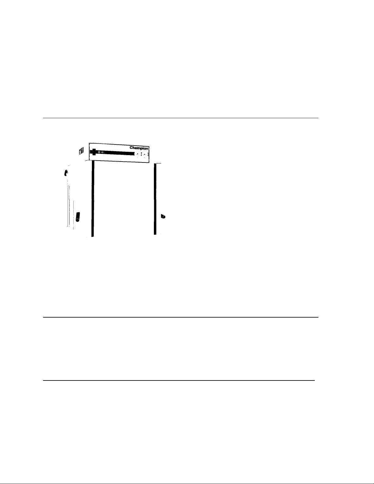
Your machine was completely assembled, inspected, and thoroughly tested at our factory before
it was shipped to your installation site.
This manual contains:
• Warranty Information
• Operation and Cleaning Instructions
• Maintenance Instructions
• Troubleshooting Guide
• Basic Service Information
• Replacement Parts Lists
• Electrical Schematics
Complete and return your warranty registration card within ten (10) days after the installation of your
machine.
All information, illustrations and specifications contained in this manual are based upon the latest product
information available at the time of publication. Champion constantly improves its products and reserves the
right to make changes at any time or to change specifications or design without notice and without incurring
obligation.
For your protection, factory authorized parts should always be used for repairs.
Replacement parts may be ordered from your Champion authorized parts distributor or from your
Champion authorized service agency. When ordering parts, please supply the model number, serial number,
voltage and phase of your machine, the part number, part description and quantity.

GENERAL
This manual covers the Champion door type dishwashing machine. These machines are fully automatic and
come equipped with a 1 -HP pump motor.
The D-series dishwasher is available in the following models:
Model Numbers
D-H1,D-HB,D-LF
The D-H1 model is a high temperature (180°F/82°C rinse) sanitizing model without booster.
The D-HB model is a high temperature (180°F/82°C rinse) sanitizing model with booster.
The D-LF is a low temperature (Min. 1200F/490C-1400F/600C Optimum) sanitizing model for use with a
sodium hypochlorite (Chlorine) based sanitizer at a minimum concentration of 50PPM in the final rinse.
Standard Equipment includes:
D-H1, D-HB, D-LF
• Automatic tank fill
• Built-in electric or steam booster heater (DHB only)
• Door activated drain
• Field convertible to comer model
• Electric tank heat
• Balanced three door lift system
• Low-water tank heat protection
• 1-hp drip-proof pump motor
• Door safety switches
• Common utility connections
• Two dish racks (peg and flat bottom)
• Detergent/chemical connection provisions
• Stainless steel front and side panels
• Top-mounted, splash-proof control console
• 60-second time cycle
• 1-1/2" O.D. gravity drain connection
• Water pressure regulating valve (mounted) (D-HB
only)
• Interchangeable upper and lower spray arms
Options (D-HB only)
• Electric booster (70°F/39°C temperature rise)
heater for 110°F/43°C supply water
• Steam injector or steam coil tank heat (steam
booster 40°F/23°C - 70°F/39°C rise)
• Single source gas booster system
Accessories
Additional dishracks:
Dish rack (peg)
Silverware rack (flat bottom)
P/N101285
P/N101273

Electrical Power Requirements
D-HB 115/60/1
D-HB 115/60/1
Model Voltage Booster Rise Machine Power Requirement
D-H1/LF 115/60/1 — 48 Amps 60 Amps
D-H1/LF 208/60/1 — 23 Amps 29 Amps
D-H1/LF 220/60/1 — 23 Amps 29 Amps
D-H1/LF 230/60/1 — 23 Amps 29 Amps
D-H1/LF 240/60/1 — 24 Amps 30 Amps
D-H1/LF 208/60/3 — 12 Amps 15 Amps
D-H1/LF 220/60/3 — 13 Amps 16 Amps
D-H1/LF 230/60/3 — 13 Amps 16 Amps
D-H1/LF 240/60/3 — 13 Amps 16 Amps
D-H1/LF 380/60/3 — 7 Amps 9 Amps
D-H1/LF 415/60/3 — 8 Amps 10 Amps
D-H1/LF 480/60/3 — 6 Amps 8 Amps
D-H1/LF 575/60/3 — 5 Amps 6 Amps
D-HB 208/60/1 40°F/23°C 59 Amps 74 Amps
D-HB 220/60/1 40°F/23°C 61 Amps 76 Amps
D-HB 230/60/1 40°F/23°C 63 Amps 79 Amps
D-HB 240/60/1 40°F/23°C 65 Amps 81 Amps
D-HB 208/60/3 40°F/23°C 33 Amps 41 Amps
D-HB 220/60/3 40°F/23°C 35 Amps 44 Amps
D-HB 230/60/3 40°F/23°C 36 Amps 45 Amps
D-HB 240/60/3 40°F/23°C 37 Amps 46 Amps
D-HB 380/60/3 40°F/23°C 20 Amps 25 Amps
D-HB 415/60/3 40°F/23°C 20 Amps 25 Amps
D-HB 480/60/3 40°F/23°C 17 Amps 21 Amps
D-HB 575/60/3 40°F/23°C 14 Amps 18 Amps
(D-HB Only) Full Load Amps (125% Service Factor)
D-HB 208/60/1 — — —
D-HB 220/60/1 — — —
D-HB 230/60/1 — — —
D-HB 240/60/1 — — —
D-HB 208/60/3 70°F/39°C 50 Amps 63 Amps
D-HB 220/60/3 70°F/39°C 52 Amps 65 Amps
D-HB 230/60/3 70°F/39°C 54 Amps 68 Amps
D-HB 240/60/3 70°F/39°C 56 Amps 70 Amps
D-HB 380/60/3 70°F/39°C 30 Amps 38 Amps
D-HB 415/60/3 70°F/39°C 33 Amps 41 Amps
D-HB 480/60/3 70°F/39°C 28 Amps 35 Amps
D-HB 575/60/3 70°F/39°C 23 Amps 29 Amps
INSTALLATION
Unpacking
CAUTION:
Care should be taken when lifting the machine to prevent damage.
1. Immediately after unpacking the machine, inspect for any shipping damage.
If damage is found, save the packing material and contact the carrier immediately.
2. Remove the dishwasher from the skid. Adjust the feet if required, then move the machine to its
permanent location.
3. Level the machine (if required) by placing a level on the top of machine and adjusting the feet.
Level the machine front-to-back and side-to-side.
4. Remove the two dishracks from the interior of the machine.
NOTE:
The installation of your machine must meet local health codes.
Changing from Straight-through to Corner Operation
Your door-type dishwasher is shipped from the factory in a straight-through configuration. The
following instructions explain how to convert your machine for comer operation.
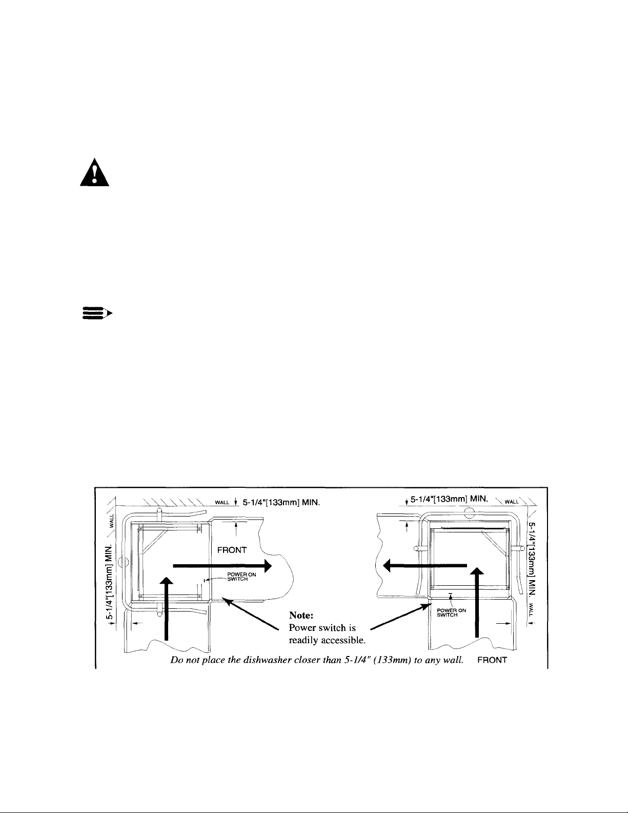
Refer to Fig. 1 below.
1. Place the dishwasher so the operator controls are readily accessible.
2. Minimum clearance from any comer wall is 5-1/4" (133mm).
Figure 1 Placement for Corner
Operation
Changing from Straight-through to Corner Operation (cont'd)
Figure
2b
Corner
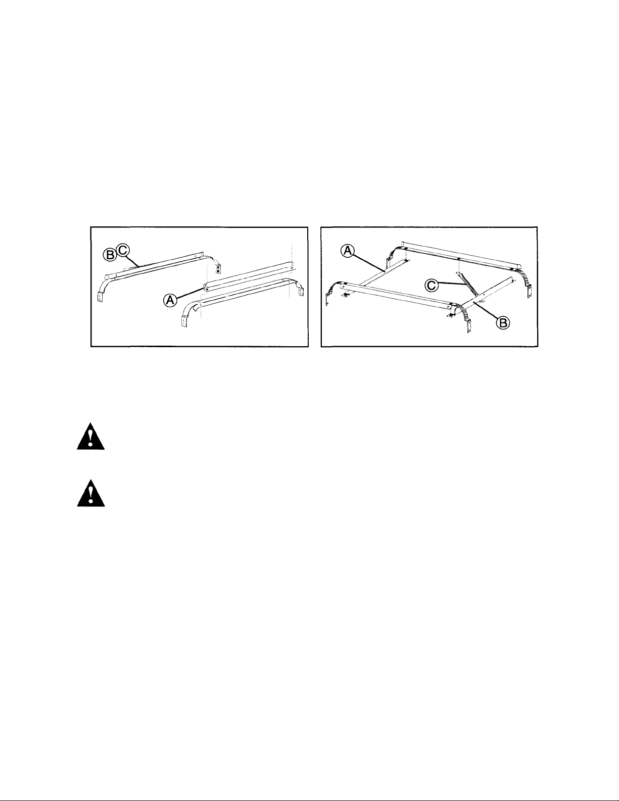
Refer to Fig. 2 and perform the steps below.
1. Remove the front rack guide (A). Discard the square spacers.
2. Move front rack guide (A) to the left side of the rack tracks. (See Fig. 2b) Use existing hardware.
3. Unbolt the track (B) and rack support rod (C).
4. Remove and save the two remaining fasteners from rear track.
5. Bolt (B) and (C) as shown in Fig. 2b.
Figure 2 Changing the Track Assembly
Figure 2a Straight-Through
Configuration
Configuration
Electrical Connections
WARNING:
Electrical and grounding connections must comply with the National Electrical Code and/or Local
Electrical Codes.
WARNING:
When working on the dishwasher, disconnect the electric service and place a tag at the disconnect
switch to indicate work is being done on that circuit.
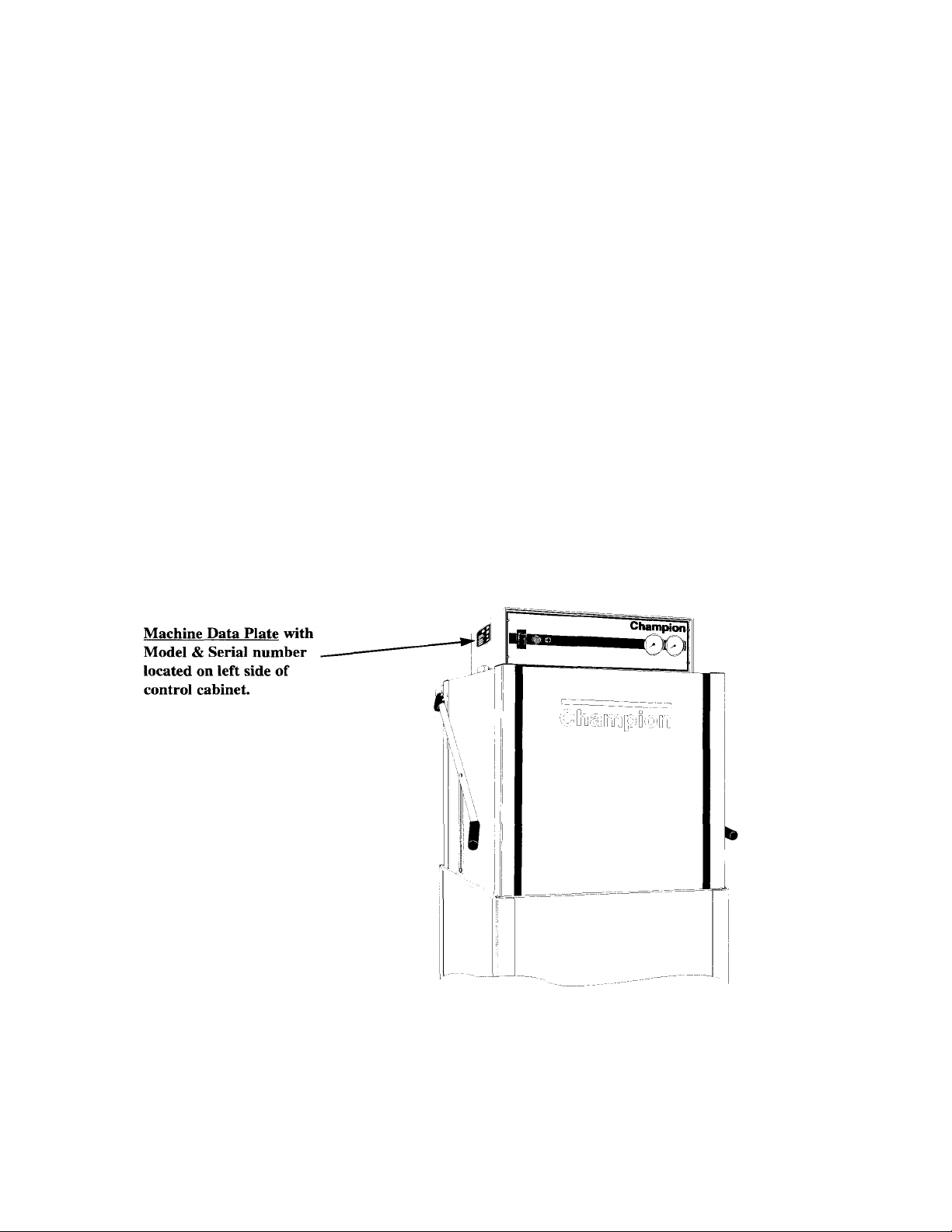
1. A qualified electrician must compare the electrical power supply with the machine electrical
specifications stamped on the MACHINE ELECTRICAL CONNECTION PLATE located inside the
top mounted control cabinet before connecting to the incoming service at a fused disconnect switch.
2. Motor rotation was set at the factory. Check the rotation of the motor shaft (CW when viewed from rear
of motor). For three phase machines, reversing the motor direction is done in the control cabinet by
reversing the wires LI and L2 on the disconnect side of the main electrical connection block. For single
phase machines, motor rotation is changed at the motor connection plate on the rear of the single phase
motor.

Electrical Connections (cont'd)
3. A knock-out is provided at the rear of the top mounted control cabinet for the electrical service
connection. A single source electrical connection has been provided. A fused disconnect switch or
circuit breaker (supplied by others) is required to protect each power supply circuit.
Plumbing Connections
CAUTION:
Plumbing connections must comply with local sanitary and plumbing codes.
Water Connections
1. Connect the hot water supply to the "Y" strainer or pressure reducing valve (PRV) at the final rinse
piping (located behind the control cabinet at the top of the machine).
2. Minimum incoming water supply temperature requirements are listed below:
D-HB with built-in 40°F/23°C rise electric booster (Minimum 140°F/60°C) (Min./Max.
flow pressure 20-22 psi/138 Kpa)
D-HB with built-in 70°F/39°C rise electric booster (Minimum 110°F/43°C) (Min./Max.
flow pressure 20-22 psi/138 Kpa)
D-H1 without built-in booster (Minimum 180°F/70°C) (Min./Max.
flow pressure 20-22 psi/138 Kpa)
D-LF (Minimum 120°F/49°C - 140°F/60°C Optimum) (Min./Max.
flow pressure 20-22 psi/138 Kpa)
3. A manual shut-off valve for steam and water (supplied by others) should be installed in supply line to
allow for servicing of the machine. The shut-off valve should be the same size or larger than the
supply line.
4. A 3/4" Pressure Regulating Valve (PRV), should be installed on the incoming water supply line if water
flow pressure exceeds 20-22 psi/138 Kpa.
A PRV is standard equipment on Model D-HB.
A PRV is not standard equipment on Models D-H1 and D-LF. The PRV
may be obtained locally or direct from Champion.
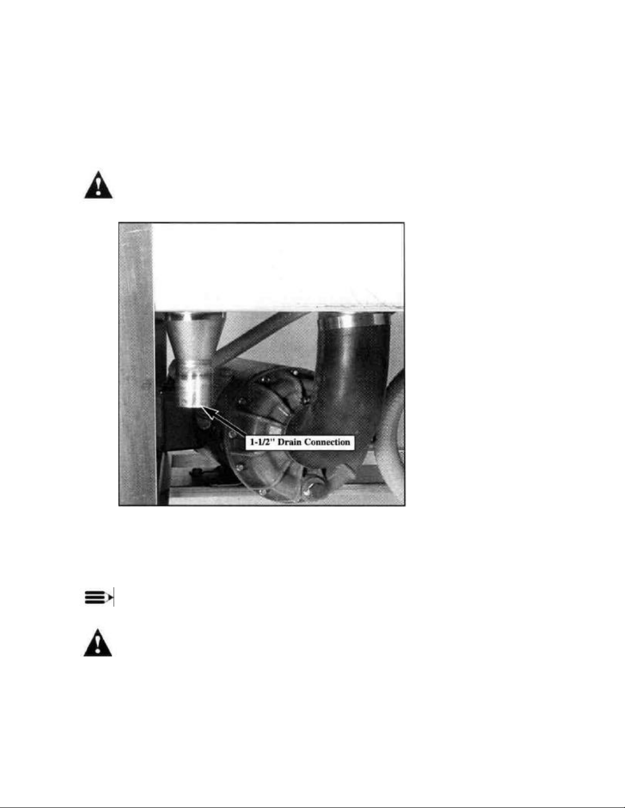
Drain Connections
Refer to Fig. 3 for the location of the machine drain.
1. Models D-HB, D-H1, and D-LF are GRAVITY DRAIN machines equipped with a 1-1/2"
hose connection point. • Drain height for ALL MODELS must not exceed 15" above floor
level.
WARNING:
Connection of the machine to a drain line higher than the machine drain height will
prevent the machine from draining properly.
Figure 3 D-HB, D-H1, D-LF 1-1/2"
Drain Connection Front Left Side of
Machine
Ventilation
NOTE:
Ventilation must comply with local sanitary and plumbing codes.
CAUTION:
Exhaust air should not be vented into a wall, ceiling, or concealed space of a building. Condensation can
cause damage.

Chemical Connections
Figure
5 D-
HB, D-
H1, D-
LF
NOTE:
Consult a qualified chemical supplier for your chemical needs.
Models D-HB. D-H1 and D-LF
1. Refer to Fig. 4
Labeled chemical signal connection points are provided inside the control cabinet
for chemical dispensing equipment (supplied by others).
Signal connection points include:
• Detergent signal 120 VAC between Wire
#10 and Wire #2 (1 AMP MAX AMP
LOAD)
• Rinse Aid/Sanitizer signal 120 VAC
between Wire #15 and Wire #2 (1 AMP
MAX AMP LOAD)
Figure 4 D-HB, D-H1, D-LF Chemical
Connection Points Left Side Interior of Control
Cabinet
Detergent
1. Refer to Fig. 5
A removable black plug, located on the rear of the wash tank is provided as a detergent probe
insertion point.
Detergent Probe Insertion Point Wash
Tank (Rear)
Chemical Connections (cont'd)
Detergent (cont'd)
2. Detergent may be added manually if dishwasher is not equipped with dispensing equipment.
Consult your chemical supplier for recommended amounts.
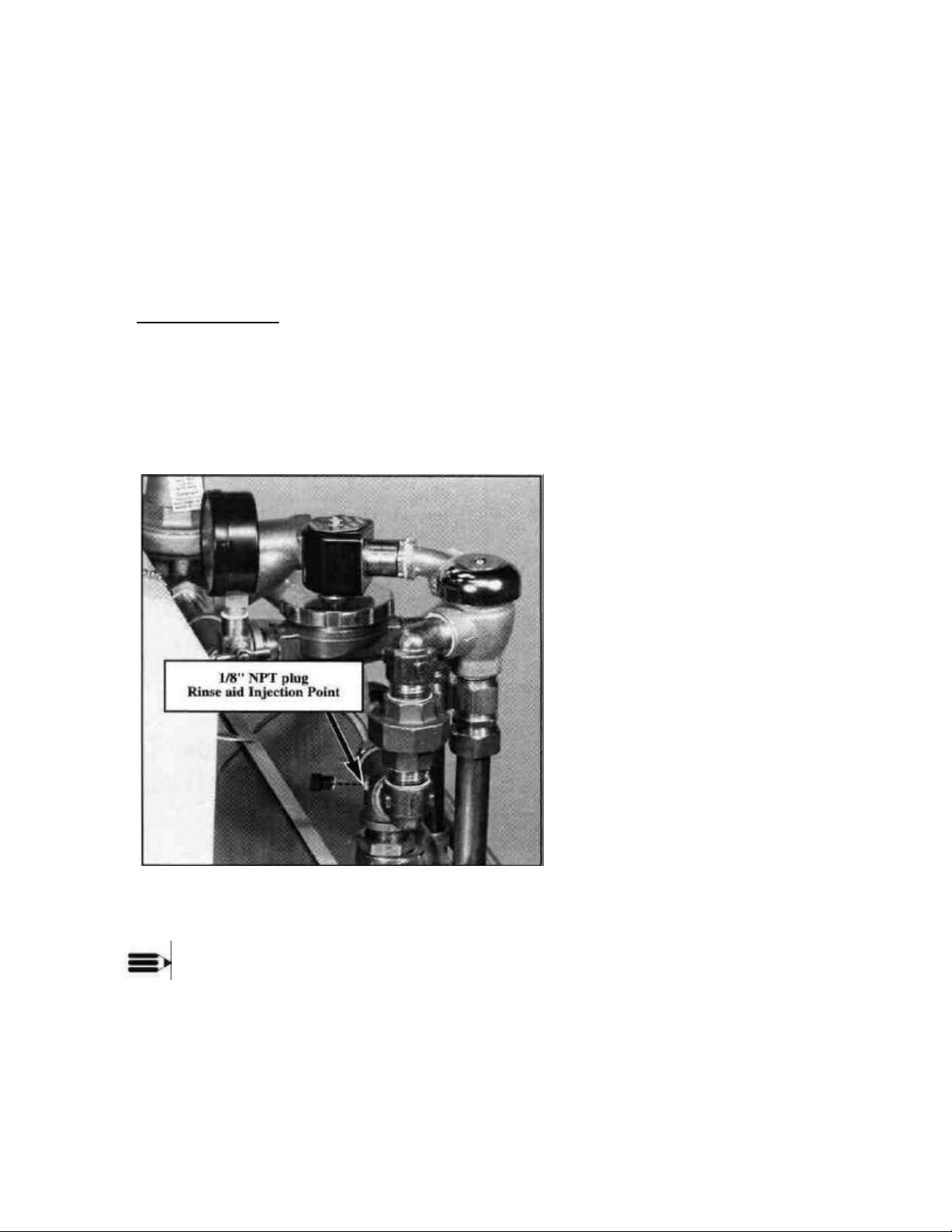
Rinse Aid/Sanitizer
Model D-HB and D-H1
Refer to Fig. 6
1. A rinse aid injection point is provided via a 1/8" NPT plug located in the final rinse piping. The plug is
located in a Tee fitting on the outlet side of the vacuum breaker. The vacuum breaker is located behind
the control cabinet at the top of the machine.
2. Use a liquid rinse aid.
Figure 6 Rinse aid Insertion
Point D-HB, D-H1 Only
NOTE:
Models D-HB and D-H1 do not require sanitizer.
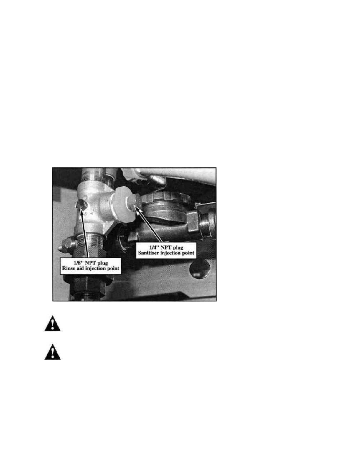
Chemical Connections (cont'd)
Figure
7 D-
LF Rinse Aid/Sanitizer
Rinse Aid/Sanitizer (cont'd)
Model D-LF Refer
to Fig. 7
1. A Rinse aid injection point is provided via a 1/8" NPT plug located in the final rinse piping. The plug is
located in a Tee fitting on the outlet side of the vacuum breaker. The vacuum breaker is located behind
the control cabinet at the top of the machine.
2. Use a liquid rinse aid.
3. A Sanitizer injection point is provided via a 1/4" NPT plug located in the final rinse piping. The plug is
located in a Tee fitting on the outlet side of the vacuum breaker. The vacuum breaker is located behind
the control cabinet at the top of the machine.
4. Use a sodium hypochlorite (Chlorine) based sanitizer at a minimum concentration of 50PPM in the
final rinse. Use chlorine test papers to verify and monitor the 50PPM chlorine level.
Injection Points
WARNING:
Never premix rinse aid with the sanitizing agent. Mixing may cause hazardous gases to form.
CAUTION:
Some metal, including silver, aluminum, and pewter are attacked by sodium hypochlorite (chlorine sanitizer).
Avoid cleaning these metals in a D-LF dishwasher.

INITIAL START-UP
Figure
9
Door Activated
After plumbing and electrical connections are completed, follow the steps below to place your machine in
service.
Model D-HB. D-H1 and D-LF Refer to
Figs. 8 and 9 below.
1. Remove any foreign material from inside the machine. Make sure scrap screens are in place.
2. Make sure drain lever assembly is closed.
3. Close the Door.
4. Turn the water and main power sources to the dishwasher ON.
5. Flip the Power switch to the ON position. The "power on" light will illuminate and the machine will
automatically fill with water.
6. Check the machine for leaks.
7. Push the Green Start Button to check automatic cycle.
8. Check pump motor rotation. Rotation is CW when viewed from rear of motor.
9. If machine checks okay, lift the drain lever assembly to drain machine. 10. Flip the power switch
to OFF.
Figure 8 Operator Controls Top
Mounted Control Cabinet
Drain Lever Assembly

OPERATION
Model D
-
HB, D
-
H1 and D
-
LF
1. Close the door and flip power switch ON Power light illuminates. Tank fills automatically and tank
heat comes on.
2. Monitor wash tank temperature gauge Wait for temperature reading to reach Min. 150°F/66°C
(D-HB, D-H1 Only) Temperature reading must be Min.
1200F-1400F/490C-600C Optimum (For D-LF Only)
3. Prescrap and load ware into rack Place dishes edgewise in peg rack, cups and bowls upside
down in flat rack, and silverware spread evenly in single
layer in flat rack.
4. Open door, insert rack
5. Close door, Push Green start button Green cycle light will illuminate. Automatic cycle
6. During Final Rinse monitor pressure gauge and final
rinse temperature gauge
7. 60-second cycle complete Green cycle light goes out.
8. Open door, remove clean rack Insert another rack of soiled ware.
9. After each meal period or every two hours operation Lift drain lever assembly to drain machine. Flush interior
begins.
Machine washes for 45 sec., then pauses for 1 sec.
Machine final rinses for 14 sec. Pressure gauge reading
must read between 20-22 PSI. Temperature gauge must
read 180-195 °F/82-91°C (D-HB, D-H1 Only) Min. 120°1400F/49°C-600C Optimum (D-LF Only)
and clean scrap screens and pump intake strainer. Check
spray arms and clean if necessary.
NOTE:
Opening the door at any time during the cycle will stop the machine. Closing the door and pushing
the Green start button will resume the cycle where it left off.
 Loading...