

Page 1

Models : DH2000 and MD2000
Champion Industries, Inc.
3765 Champion Boulevard
Winston-Salem, NC 27105
Toll-free: 1-(800) 858-4477
Fax: 1-(336) 661-1660
ChampionMoyer Diebel
2674 North Service Road
Jordan Station, Ontario, Canada
Toll-free: 1-(800) 263-5798
Fax: 1-(905) 562-4618
Field Installation Instructions for
Drain Tempering Kit
Part No. 900923
WARNING:
Electrocution or serious injury may result when working on an
energized circuit.
Disconnect power at the main breaker or service disconnect
switch before working on the circuit.
Lock-out and tag the breaker to indicate that work is being
performed on the circuit.
Form No. 114695 Rev. A
Printed in U.S.A.
Copyright © 2009 All rights reserved
9.24.09
1
Page 2
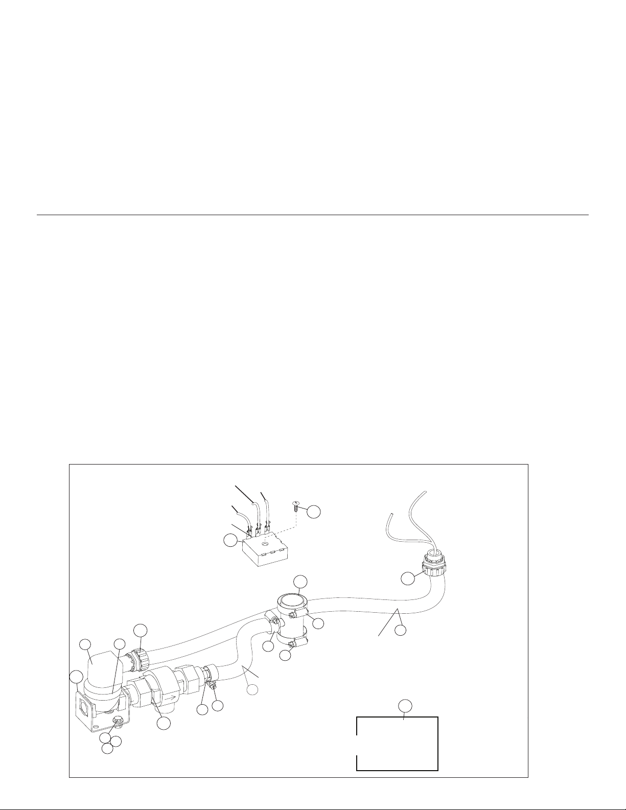
Introduction:
Timer
Located in Top Cabinet
Wire #3
Wire #2
Wire #52
Wire #2
Wire #51
Located in Junction Box
Note:
1. See Schematic # 702119 Rev.B or later for wiring references.
2. Revisions to current drawing will revise instructions to Form No. 114695.
Rubber Hose measures15"/38cm.
1/2" Flexible Conduit measures
26"/66cm.
14
9
6
10
8
1
4
17
3
7
3
12
15
18
13
11
11
5
5
2
The drain water tempering kit is designed to inject cold water into the dishwasher drain water efuent to ensure that the
temperature of the water leaving the dishwasher drain and/or overow does not exceed a temperature of 140°F/60°C.
This operation is most often required by the local plumbing and sanitary codes of the location.
The following instructions describe how to perform a eld installation of the drain water tempering kit provided
by the manufacturer of the Champion Model DH2000 and the Champion-Moyer Diebel Model MD2000.
Kit Components:
The Drain Water Tempering Kit P/N 900923 may be installed at the factory or shipped as a separate part to be installed
at the installation site. Refer to the parts list below to ensure all the parts necessary for the installation are available.
Refer to the parts list and illustration below.
Item No. Part No. Description Qty.
1 100734 BOLT, HEX HD. 1/4-20 X 1/2" SST 2
2 100209 NIPPLE, 1/2" npt X CLOSE BRASS 1
3 105994 CLAMP, HOSE, M10, 14/27 SST, GEAR-TYPE 2
4 106026 WASHER, FLAT 1/4", SST 2
5 107340 CLAMP, HOSE M28, SST, GEAR-TYPE 2
6 107417 1/2" 1.D RUBBER RE-INFORCED, 15"/38cm 1
7 107419 BARB, HOSE ST., 1/2" NPT X 1/2" HOSE, BRASS 1
8 109886 VALVE, SOLENOID, 1.2" NPT 120VAC COIL 1
-- 109902 KIT, VALVE REPAIR A/R
-- 108516 COIL, SOLENOID 120VAC A/R
9 110551 BACKFLOW, PREVENTER, 1/2" NPT BRONZE 1
10 110834 CONDUIT, 1/2", SEALTITE BLACK 26"/66"/66cm 1
11 110836 FITTING, STRAIGHT, 1/2" SEALTITE 1
12 114662 TIMER, INFITEC 30 SECOND 1
13 114695 INSTALLATION INSTUCTIONS 1
14 0312146 BRACKET, VALVE FWR 1
15 333280 TEE, WELDMENT, 1-3/8" X 1/2" BARB X 1-3/8" 1
16 106482 WASHER, LOCK SPLIT 1/4" SST 2
17 100003 NUT, PLAIN 1/4-20 SST 2
18 107564 SCREW, 6-32 X 1" TRUSS HD. SST 1
2
Page 3

Conversion Installation:
Follow the lettered steps (A, B, C, D. E, F) to make the installation easier.
A. Remove the existing hose connected on the overow tube.
Cut the hose in half. Install the Tee tting with the Tee facing the solenoid.
Slide the hoses in place and tighten.
B. Install the solenoid bracket to the base of the machine in the holes
provided. Use 1/4-20 bolts and mounting hardware.
C. Connect the 1/2" rubber hose to the Tee that was installed in the overow.
D. Thread the solenoid wires through the sealtite tubing so they extend into
the junction box.
E. Wire nut the #2 wire and the #51 wire in the existing wire nut connectors.
Close the junction box.
F. Connect a 1/2" cold water line to the inlet of the solenoid valve. Install a
pressure regulating valve (PRV) before the solenoid in order to adjust the
cold water pressure to 20-25 PSI/137.8-172.4 kPa owing pressure.
Install a 1/2" or larger valve before the PRV for servicing.
The kit is installed on the base
of the machine.
F
B
Refer to the next page for the electrical connections in the Top Cabinet.
E
#2
#51
A
D
C
A
C
D
Refer to the next page for the electrical connections that are made in the Top Cabinet to complete the Conversion Installation
3
Page 4

WARNING:
Electrocution or serious injury may result when working on an
energized circuit.
Disconnect power at the main breaker or service disconnect
switch before working on the circuit.
Lock-out and tag the breaker to indicate that work is being
performed on the circuit.
Top Cabinet Electrical Installation:
Follow the lettered steps (A, B, C) to make the installation.
B
52
CAUTION:
Make sure main power to the
machine is disconnected to
the machine before performing
any work.
XFRM
A. Mount the new timer to the
base of the cabinet using
the 6-32 x 1" Truss Hd.
screw as shown.
C
2
3
52
2-1/2"
A
B. Connect the wire #52
contained in the kit from
the terminal on the timer
to relay 3CR as shown.
C. Install a jumper wire from
terminals #2 and #3 as
shown.
D. Replace the cover.
Test Operation:
1. Turn main power and
water supplies to the
machine.
2. Turn the dishwasher
power switch ON. The
machine will ll and the
tempering solenoid valve
will open, then close when
the machine is full.
3. The tempering valve
should open during the
nal rinse then close.
4. Drain the dishwasher. The
tempering valve should
open for 30-seconds and
then close.
4
 Loading...