

Champion 44, 64, 66PW Service Manual
Champion
The Dishwashing Machine Specialists
For models beginning wit/i Serial No. R31 71
For models beginning with Serial No. R3171
Single Tank
Single Tank
44
44
54
54
44LT
44LT
66LT
66LT
44W5
44WS
66PWWS
66PWWS
44 MODULAR
44
44
44 MODULAR
44DR
44DR
44DRWS
44DRWS
66DRPW
66DRPW
66DRWSPW
66DRW SPW
Technical Manual
Technical Manual
E-Series Single Tank
E-Series Single Tank
and Two Tank
and Two Tank
Rack Conveyor
Rack Conveyor
with/without Prewash
with/without Prewash
Two Tank
Two Tank
64
64
72
72
84
84
64 MODULAR
64 MODULAR
64
64
Single Tank wlPrewash
Single Tank w/Prewash
66PW
66PW
7OFFPW 8ODRIIDPW
70FFPW
I
-
66PW
66PW
May, 2005
May, 2005
P. 0. Box 4149
P. O. Box 4149
Winston-Salem, North Carolina 27115-4149
Winston-Salem, North Carolina 27115-4149
336/661-1556 Fax: 336/661-1660
336/661-1556 Fax: 336/661-1660
8OHDPW
80HDPW
66PW MODULAR
66PW MODULAR
76PW
76PW
8OFFPW
80FFPW
9OHDPW
90HDPW
Two Tank wlPrewash
Two Tank w/Prewash
86PW 94FFPW
86PW
90FFPW
9OFFPW 1O8HDPW
100HDPW 1O6PW
100HDPW
86PW MODULAR
86PW MODULAR 11OFFPW
94PW 12OHDPW
94PW
66DRPW
66DRPW
80DRHDPW
8ODRW SHDPW
80DRWSHDPW
94FFPW
108HDPW
106PW
110FFPW
120HDPW
Machine Serial No.
Machine Serial No.
Manual PIN 113867 Rev D
Manual P/N 113867 Rev D
2674 N. Serice Road
2674 N. Service Road
Jordan Station, Ontario, Canada LOR iSO
Jordan Station, Ontario, Canada L0R 1S0
905/562-4195 Fax: 905/562-4618
905/562-4195 Fax: 905/562-4618
PDF compression, OCR, web optimization using a watermarked evaluation copy of CVISION PDFCompressorPDF compression, OCR, web optimization using a watermarked evaluation copy of CVISION PDFCompressor

Complete the information below so it will be available for quick reference.
Model Number Serial Number
Voltage and Phase
Champion Service Agency Phone
Champion Parts Source Phone
Champion Service:
Champion (USA) Champion (Canada)
Phone: 1 (336) 661-1556 Phone: 1 (905) 562-4195
1 (800) 858-4477 1 (800) 263-5798
Fax: 1 (336) 661-1660 Fax: 1 (905) 562-4618
We strongly recommend that you Fax your orders.
NOTE: When calling to order parts, be sure to have the model number, serial
number, voltage and phase of your machine.
COPYRIGHT © 2005 by Champion Industries, Inc.
PDF compression, OCR, web optimization using a watermarked evaluation copy of CVISION PDFCompressorPDF compression, OCR, web optimization using a watermarked evaluation copy of CVISION PDFCompressor

REVISIONS
REVISION HISTREVISION HIST
REVISION HIST
REVISION HISTREVISION HIST
Revision Revised Serial Number Comments
Date Pages Effectivity
07/15/04 All First issue of manual and replacement parts
08/31/04 7 Revised operation procedure.
08/31/04 12 Revised the pump timer operation sequence.
08/31/04 13 Revised the float switch inforamtion.
8/31/04 14 Revised the terminal connections drawings and
8/31/04 18 Added drive motor wiring drawings and information.
09/01/04 20 Part number 328473 replaced by 328977. Added 36"
9/01/04 20, 23, 25 R3448 Added new door catch components.
9/01/04 23 Part number 327890 relpaced by 328974. Added
9/01/04 25 Part number 327891 replaced by 328975. Added E84
OROR
OR
OROR
YY
Y
YY
inserted figure number for electric booster.
Prewash panels.
entrance and exit curtain baffles.
front panels.
9/01/04 31 Part number 328799 replaced by 328450. Added new
cradle bracket for two tank machines.
9/01/04 37 Updated part numbers for scrap screens and refuse
baskets.
9/01/04 61, 63 Updated part numbers for drain levers and overflow
rod.
9/01/04 64, 66 Corrected piping drawings.
9/01/04 73 Changed part number 113727 discharge hose
to 112807.
12/16/04 Added 575 volt elements and corrected part number
2/16/05 Added revised schematics.
5/16/05 Added revised schematics.
51, 53, 77
for 10KW element.
91
91
PDF compression, OCR, web optimization using a watermarked evaluation copy of CVISION PDFCompressorPDF compression, OCR, web optimization using a watermarked evaluation copy of CVISION PDFCompressor
i

REVISIONS
REV ISI ON RECORDREV ISI ON RECORD
REV ISI ON RECORD
REV ISI ON RECORDREV ISI ON RECORD
(CON T’D)(CON T’D)
(CON T’D)
(CON T’D)(CON T’D)
PDF compression, OCR, web optimization using a watermarked evaluation copy of CVISION PDFCompressorPDF compression, OCR, web optimization using a watermarked evaluation copy of CVISION PDFCompressor
ii

TABLE OF CONTENTS
CON TEN TS
Page
REVISION HISTORY .................................................................................................................... i
WARRANTY .................................................................................................................................. v
SAFETY SUMMARY..................................................................................................................... vi
INTRODUCTION ........................................................................................................................... 1
GENERAL....................................................................................................................................... 2
INSTALLATION ............................................................................................................................ 3
Unpacking........................................................................................................................... 3
Plumbing Connnections ................................................................................................... 3
Electrical Connections ...................................................................................................... 4
Ventilation Connections ................................................................................................... 4
Chemical Connections...................................................................................................... 5
Curtain Locations .............................................................................................................. 5
Completing Installation .................................................................................................... 6
OPERATION .................................................................................................................................. 8
Inital Startup ...................................................................................................................... 8
Basic Operation ................................................................................................................. 8
MAINTENANCE ........................................................................................................................... 9
Maintenance Schedule...................................................................................................... 9
Deliming ............................................................................................................................ 10
ELECTRICAL SERVICE ............................................................................................................... 11
REPLACEMENT PARTS ...............................................................................................................19
ELECTRICAL SCHEMATICS ...................................................................................................... 93
LIST OF FIGU RES
Figure 1 — Motor Rotation ....................................................................................................... 4
Figure 2 — Scrap Basket Removal ........................................................................................... 9
Figure 3 — Motor Overload ...................................................................................................... 9
Figure 4 — Unhooking Upper Arm ......................................................................................... 9
Figure 5 — Upper Wash Arm Removal ................................................................................... 9
Figure 6 — Lower Wash Arm Removal ................................................................................... 9
Figure 7 — End Cap Removal .................................................................................................. 9
Figure 8 — Fuse Blocks ............................................................................................................ 11
Figure 9 — Motor Overloads .................................................................................................... 11
Figure 10 — Pump Timer ............................................................................................................ 1 2
Figure 11 — Dual Float Switch ................................................................................................... 1 3
Figure 12 — Tank Heat Thermostats .......................................................................................... 14
Figure 13 — Booster Thermostat Location ................................................................................ 1 4
Figure 14 — Booster High Limit Thermostat ............................................................................ 1 4
Figure 15 — Prewash Panels, Doors and Miscellaneous .......................................................... 20
PDF compression, OCR, web optimization using a watermarked evaluation copy of CVISION PDFCompressorPDF compression, OCR, web optimization using a watermarked evaluation copy of CVISION PDFCompressor
iii

TABLE OF CONTENTS
Figure 16 — Single Tank Panels, Doors and Miscellaneous .................................................... 22
Figure 17 — Two Tank Doors, Panels and Miscellaneous ....................................................... 24
Figure 18 — Drive Motor Assembly .......................................................................................... 2 6
Figure 19 — Drive Assembly...................................................................................................... 2 8
Figure 20 — Prewash Track and Cradle Assembly ................................................................... 3 0
Figure 21 — Single Tank Track and Cradle Assembly............................................................. 3 2
Figure 22 — Two Tank Track and Cradle Assembly ................................................................ 34
Figure 23 — Prewash Screens ..................................................................................................... 36
Figure 24 — Single Tank Scrap Screens .................................................................................... 28
Figure 25 — Two Tank Scrap Screens ....................................................................................... 40
Figure 26 — Prewash Spray Arms .............................................................................................. 42
Figure 27 — Single Tank Wash Arms (Left to Right Shown) .................................................. 4 4
Figure 28 — Two Tank Wash and Rinse Arms ( Left to Right Shown) .................................. 46
Figure 29 — Float Switch ............................................................................................................ 48
Figure 30 — Single Tank Electric Tank Heat ............................................................................ 50
Figure 31 — Two Tank Electric Tank Heat ................................................................................ 52
Figure 32 — Single Tank Steam Tank Heat ............................................................................... 54
Figure 33 — Two Tank Steam Tank Heat .................................................................................. 56
Figure 34 — Tank Thermostats ................................................................................................... 58
Figure 35 — Prewash Overflow .................................................................................................. 60
Figure 36 — Single Tank and Two Tank Overflow Assembly ................................................ 62
Figure 37 — Final Rinse Piping w/Booster ................................................................................ 6 4
Figure 38 — Final Rinse Piping no Booster/ with Steam Booster ........................................... 6 6
Figure 39 — Final Rinse Drain Assembly ................................................................................. 68
Figure 40 — Prewash Pump Suction/Discharge ........................................................................ 7 0
Figure 41 — Wash/Rinse Pump Suction/Discharge .................................................................. 72
Figure 42 — Pump Assembly ..................................................................................................... 7 4
Figure 43 — 40°/60° Rise Electric Booster ............................................................................... 76
Figure 44 — 70° Rise Electric Booster ....................................................................................... 7 8
Figure 45 — Control Cabinet ...................................................................................................... 80
Figure 46 — New Style Vent Cowls (Shown Mounted to Prewash)(Optional) ...................... 8 2
Figure 47 — Standard Vent Cowls (Optional) ........................................................................... 84
Figure 48 — Racks ....................................................................................................................... 88
CON TENTS (CON T.)
LIST OF FIGU RES
PDF compression, OCR, web optimization using a watermarked evaluation copy of CVISION PDFCompressorPDF compression, OCR, web optimization using a watermarked evaluation copy of CVISION PDFCompressor
iv

LI MI TED WARRAN TYLI MI TED WARRAN TY
LI MI TED WARRAN TY
LI MI TED WARRAN TYLI MI TED WARRAN TY
Champion Industries Inc. (herein referred to as Champion), P.O. Box 4149, Winston-Salem, North Carolina 27115,
and P.O. Box 301, 2674 N. Service Road, Jordan Station, Canada, L0R 1S0, warrants machines, and parts, as set out
below.
Warranty of Machines: Champion warrants all new machines of its manufacture bearing the name
"Champion" and installed within the United States and Canada to be free from defects in material and workman
ship for a period of one (1) year after the date of installation or fifteen (15) months after the date of shipment by
Champion, whichever occurs first. [See below for special provisions relating to glasswashers.] The warranty
registration card must be returned to Champion within ten (10) days after installation. If warranty card is not
returned to Champion within such period, the warranty will expire after one year from the date of shipment.
Champion will not assume any responsibility for extra costs for installation in any area where there are
jurisdictional problems with local trades or unions.
If a defect in workmanship or material is found to exist within the warranty period, Champion, at its election,
will either repair or replace the defective machine or accept return of the machine for full credit; provided, how
ever, as to glasswashers, Champion's obligation with respect to labor associated with any repairs shall end
(a) 120 days after shipment, or (b) 90 days after installation, whichever occurs first. In the event that Champion
elects to repair, the labor and work to be performed in connection with the warranty shall be done during regular
working hours by a Champion authorized service technician. Defective parts become the property of Champion.
Use of replacement parts not authorized by Champion will relieve Champion of all further liability in connection with its warranty. In no event will Champion's warranty obligation exceed Champion's charge for the
machine. The following are not covered by Champion's warranty:
WARRANTY
a. Lighting of gas pilots or burners.
b. Cleaning of gas lines.
c. Replacement of fuses or resetting of overload breakers.
d. Adjustment of thermostats.
e. Adjustment of clutches.
f. Opening or closing of utility supply valves or switching of electrical supply current.
g. Cleaning of valves, strainers, screens, nozzles, or spray pipes.
h. Performance of regular maintenance and cleaning as outlined in operator’s guide.
i. Damages resulting from water conditions, accidents, alterations, improper use, abuse,
tampering, improper installation, or failure to follow maintenance and operation procedures.
j. Wear on Pulper cutter blocks, pulse vanes, and auger brush.
Examples of the defects not covered by warranty include, but are not limited to: (1) Damage to the exterior or
interior finish as a result of the above, (2) Use with utility service other than that designated on the rating plate,
(3) Improper connection to utility service, (4) Inadequate or excessive water pressure, (5) Corrosion from
chemicals dispensed in excess of recommended concentrations, (6) Failure of electrical components due to
connection of chemical dispensing equipment installed by others, (7) Leaks or damage resulting from such
leaks caused by the installer, including those at machine table connections or by connection of chemical
dispensing equipment installed by others, (8) Failure to comply with local building codes, (9) Damage caused
by labor dispute.
Warranty of Parts: Champion warrants all new machine parts produced or authorized by Champion to be free
from defects in material and workmanship for a period of 90 days from date of invoice. If any defect in
material and workmanship is found to exist within the warranty period Champion will replace the defective
part without charge.
DISCLAIMER OF WARRANTIES AND LIMITATIONS OF LIABILITY. CHAMPION'S WARRANTY
IS ONLY TO THE EXTENT REFLECTED ABOVE. CHAMPION MAKES NO OTHER WARRANTIES,
EXPRESS OR IMPLIED, INCLUDING, BUT NOT LIMITED, TO ANY WARRANTY OF
MERCHANTABILITY, OR FITNESS OF PURPOSE. CHAMPION SHALL NOT BE LIABLE FOR
INCIDENTAL OR CONSEQUENTIAL DAMAGES. THE REMEDIES SET OUT ABOVE ARE
THE EXCLUSIVE REMEDIES FOR ANY DEFECTS FOUND TO EXIST IN CHAMPION DISHWASHING
MACHINES AND CHAMPION PARTS, AND ALL OTHER REMEDIES ARE EXCLUDED,
INCLUDING ANY LIABILITY FOR INCIDENTALS OR CONSEQUENTIAL DAMAGES.
Champion does not authorize any other person, including persons who deal in Champion dishwashing
machines to change this warranty or create any other obligation in connection with Champion Dishwashing Machines.
PDF compression, OCR, web optimization using a watermarked evaluation copy of CVISION PDFCompressorPDF compression, OCR, web optimization using a watermarked evaluation copy of CVISION PDFCompressor
v

SAFETY SUMMARY
SAFET Y SU MM ARSAFET Y SU MM AR
SAFET Y SU MM AR
SAFET Y SU MM ARSAFET Y SU MM AR
YY
Y
YY
Safet y Sym bols
• The following symbols appear throughut this manual alerting you to potential hazards. Statements
associated with each symbol are printed on italics.
WARN I NG:
Warning statements indicate any condition or practice that could result in personal injury
or possible loss of life.
CAU TI ON :
!
Caution statements indicate any condition or practice which, if not strictly observed or
remedied, could result in damage to or destruction of the dishwasher.
NOTE:
Note statements indicate any condition or practice which, if observed, will help
in the safe completion of a task.
Gene ral Sa fe t y Rule s
• The following general safety rules must be observed in addition to the specific cautions
and warnings presented in this manual.
• Your Champion pot and pan washer uses hot water to clean and sanitize a variety of wares.
Machine surfaces and wares become hot during and immediately following normal
operations. Operators should use caution when loading and unloading wares from the
machine.
• Operators must NOT bypass a safety interlock or control(s) to operate unit.
• The service and maintenance instructions contained in this manual are intended for
qualified service personnel. These instructions assume that you are trained in basic
electricity and mechanical theory. If you are not a trained technician, then do not
attempt to adjust or repair the dishwasher as serious personal injury or damage to
the dishwasher may result.
PDF compression, OCR, web optimization using a watermarked evaluation copy of CVISION PDFCompressorPDF compression, OCR, web optimization using a watermarked evaluation copy of CVISION PDFCompressor
vi

INTRODUCTION
INTRODU CTI ON
Welcome to Champion....
and thank you for allowing us to take care of your dishwashing needs.
This manual covers several models. Model numbers are shown on the front cover.
Your machine has been completely assembled, inspected, and thoroughly tested at our
factory before it was shipped to your installation site.
This manual contains:
• Warranty information
• Operation and cleaning instructions
• Maintenance instructions
• Troubleshooting guide
• Basic service information
• Replacement parts lists
• Electrical schematics
Complete and return your warranty registration card within ten (10) days after the installation of your machine.
All information, illustrations and specifications contained in this manual are based upon the
latest product information available at the time of publication. Champion constantly improves its products and reserves the right to make changes at any time or to change specifications or design without notice and without incurring obligation.
For your protection, factory authorized parts should always be used for repairs.
Replacement parts may be ordered from your Champion authorized service agency. When
ordering parts, please supply the model number, serial number, voltage and phase of your
machine, the part number, part description, and quantity.
PDF compression, OCR, web optimization using a watermarked evaluation copy of CVISION PDFCompressorPDF compression, OCR, web optimization using a watermarked evaluation copy of CVISION PDFCompressor
1

GENERAL
GENERAL
This manual covers the Champion single tank and two tank rack conveyor dishwashing
machines. These machines are fully automatic and are equipped with 1 HP prewash and
2HP wash and rinse pump motors (depending on the model) and a 1/6 HP conveyor drive
motor. All models are available for a right-to-left or left-to-right operation.
These series of dishwashers are modular in design. The following models and options are
covered in this manual:
Model Numbers
Single Tank - Basic.....................................................44, 54, 44 WS, 44 LT
Single Tank with 22" Prewash...................................66 PW, 76 PW, 66 WS, 66 LT PW
Single Tank with 36" Prewash....................................80 HDPW, 90 HDPW, 80WS HDPW
Single Tank with 26" Front Feed Prewash..................70 FFPW,80 FFPW, 70 WS FFPW
• The 44 and 54 basic models along with their respective prewash options, are high temperature (180°F/80°C final rinse) sanitizing models.
• The 44 WS models along with their respective prewash options, are water and energy
saving, high temperature (180°F/80°C final rinse) sanitizing models.
• The 44 LT model, along with its respective prewash option, is a low temperature (140°F/
60°C final rinse), chemical sanitizing model for use with sodium hypochlorite solution
(chlorine bleach) as the sanitizing agent.
Two Tank - Basic........................................................64, 72, 84
Two Tank with 22" Prewash......................................86 PW, 94 PW, 106 PW
Two Tank with 36" Prewash.......................................100 HDPW, 108 HDPW, 120 HDPW
Two Tank with 26" Front Feed Prewash.....................90 FFPW, 98 FFPW, 110 FFPW
• The 64, 72 and 84 basic models, along with their respective prewash options, are high
temperature (180°F/80°C final rinse) sanitizing models.
PDF compression, OCR, web optimization using a watermarked evaluation copy of CVISION PDFCompressorPDF compression, OCR, web optimization using a watermarked evaluation copy of CVISION PDFCompressor
2

INSTALLATION
Unpacking
CAUTION:
!
Care should be taken when lifting the machine to avoid damaging the piping under the
base. Remove the dishwasher front panels and lift from the front with a forklift.
1. Immediately after unpacking your machine, inspect for any shipping damage. If damage is found, save the packing material and contact the carrier immediately.
2. Remove the dishwasher from the skids. Adjust the feet if required, then move the
machine to its permanent location. The machine should not be installed within 6 inches
[153mm] of any wall or structure.
3. Level the machine by placing a level on top of the machine and adjust the feet. Level
the machine by unscrewing the feet from the base. Adjust from the front-to-back and
side-to-side.
INSTALLATION
Plumbing Connections
CAUTION:
!
Plumbing connections must comply with local sanitary and plumbing codes.
1. Connect the hot water supply at the final rinse piping connection located behind the
control cabinet at the top of the machine.
2. A “Y” strainer is provided by Champion for machines without booster. A pressure
reducing valve (PRV) is provided by Champion for machines with built-in boosters.
3. If the incoming hot water supply pressure exceeds 25psi [173kPa] at machine, a PRV
must be installed and set to 20-22psi [138-151 kPa]. The PRV may be purchased from
Champion or supplied by others.
4. Install a manual shut-off valve in the steam and water supply lines to accommodate
servicing the machine. The valve should be the same size as/or larger than the supply
line.
5. Provide suitable gravity drain to connect to a 1-1/2" NPT drain pipe.
PDF compression, OCR, web optimization using a watermarked evaluation copy of CVISION PDFCompressorPDF compression, OCR, web optimization using a watermarked evaluation copy of CVISION PDFCompressor
3
INSTALLATION
INSTALLATION (CONT.)
Electrical Connections
1. Compare the electrical specifications on the machine electrical connection plate (located
NOTE:
Electrical and grounding connections must comply with the National Electrical Code
and/or Local Electrical Codes.
WARNING:
When working on the dishwasher, disconnect the electric service and tag it to indicate
work is being done on that circuit.
NOTE:
Electric boosters require a separate electrical connection (except the 44WS and 66 WS
PW models that have a single point connection).
A fused disconnect switch or circuit breaker (supplied by user) is required to protect
each power supply circuit.
inside the control cabinet) to the electrical power supply before connecting to the
incoming service at a fused disconnect switch.
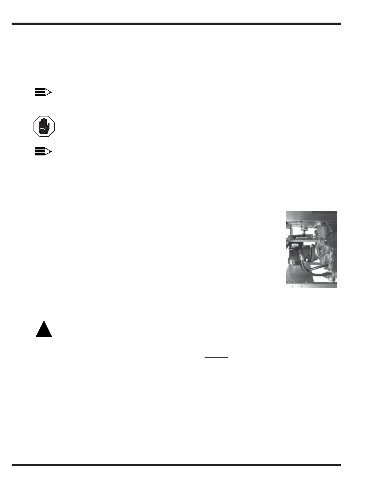
2. Motor rotation is set at the factory. Ensure proper rotation of the conveyor drive
shaft (red arrow on side of motor shows direction of rotation). Single phase
drive motor (208-240V only) rotation must be changed at the drive motor
junction box. Three phase drive motor (480-575V) rotation must be reversed
in the control cabinet. Reversing the pump motor(s) direction is done in the
control cabinet by reversing the wires L1 and L2 on the disconnect switch side
of the main electrical connection terminal block (refer to the electrical diagrams
in the back of this manual).
3. A knock-out plug is provided at the rear of the control cabinet for electrical
service connections.
Ventilation
CAUTION:
!
Exhaust air should never be vented into a wall, ceiling, or concealed space if a building
as condensation will cause damage.
1. Stainless steel watertight ducting should be installed
407mm] vent stacks at the load and unload ends. A minimum of 6 air changes per hour
of kitchen air is recommended. The typical exhaust ventilation requirements for a rack
machine using a 180°F/82°C final rinse are:
• The load end requires 150 CFM @ 1/4" (SP), [71 Liters/Sec] with prewash.
INSIDE the 4" x 16" [102mm x
Figure 1- Motor
Rotation
• The load end requires 200 CFM @ 1/4" (SP), [95 Liters/Sec] without prewash.
• The unload end requires 400 CFM @ 1/4" (SP), [189 Liters/Sec].
2. An adjustable damper is supplied with the optional vent stacks for regulating the
exhaust volume.
PDF compression, OCR, web optimization using a watermarked evaluation copy of CVISION PDFCompressorPDF compression, OCR, web optimization using a watermarked evaluation copy of CVISION PDFCompressor
4
INSTALLATION (CONT.)
Chemical Connections
1. Use a qualified detergent/chemical supplier for detergent/chemical and dispensing
equipment needs.
2. Labeled detergent control circuit connection terminals are provided in
the control cabinet for detergent and rinse agent/sanitizer dispensing
equipment (supplied by others).
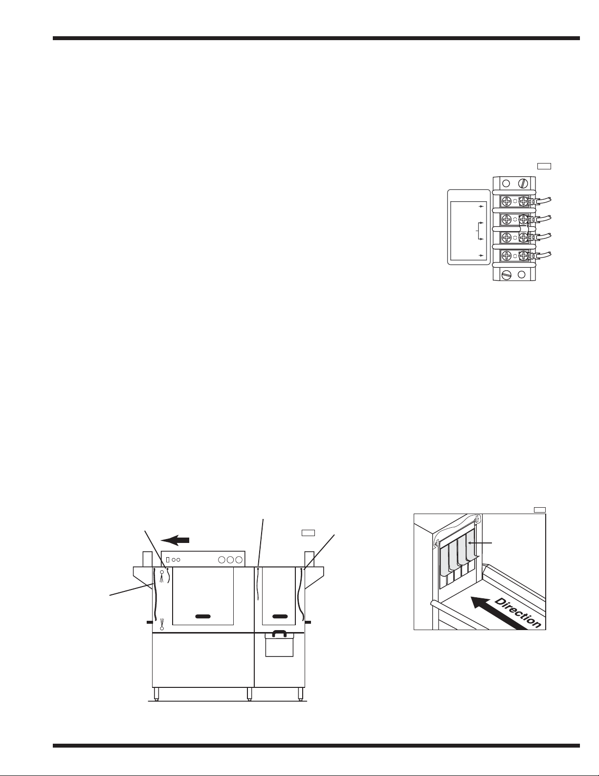
3. The illustration on the right, shows the terminal board for the current
production machines . The signal connection points include:
• Detergent signal 120VAC, 1Amp max amp load
• Rinse aid/Sanitizer signal 120VAC, 1Amp max amp load
SIGNAL ONLY
120V
RINSE AID/
SANI
COMMON
DETERGENT
120V
INSTALLATION
1R001
4. A removable black plug is provided in the load end side of the wash
tank (behind the drive motor) for installation of the detergent
conductivity cell.
Chemical Connection
Terminal Board
Curtain Locations
1. Refer to the illustrations below and hang the curtains as shown.
J-hooks are located in the corners of each section to accept the curtain rods.
• Standard long curtains 24" x 20-1/4" [610mm x 515mm]
• High hood long curtains 24" x 22-3/4" [610mm x 578mm]
• Standard short curtains 24" x 13-/14" [610mm x 337mm]
• High hood short curtains 24" x 20-1/4" [610mm x 515mm]
• Final rinse curtain 24" x 6-1/4" [610mm x 159mm]
2. Make sure the that the short flaps of the curtains face the load end of the dishwasher.
The longest curtains always go on each end of the dishwasher.
Final rinse
curtain
R-L Direction
Center Curtain
Long curtain
1R002
Short Row
1R003
Long curtain
Load End
Short row of curtains face out to
the load end (or unload
WASH
PRE
WASH
Curtain Locations
(machine with prewash shown)
PDF compression, OCR, web optimization using a watermarked evaluation copy of CVISION PDFCompressorPDF compression, OCR, web optimization using a watermarked evaluation copy of CVISION PDFCompressor
depending the location of the
curtain) of the dishwasher.
5

INSTALLATION
INSTALLATION (CONT’)
Completing Installation
!
1. Remove any foreign material from inside of the machine.
2. Check to insure that the drains/overflow pipes are operational and sealed.
3. Position scrap screens on the supports above the tanks.
4. After all plumbing and electrical connections are completed, fill the tank and wait 10
5. Drain the tank and check the drain lines for leaks.
6. The formed down lip of the dishtable should be placed inside of the machine. The
WARNING:
Do not insert racks into the machine before the tanks fill with water and have reached
the proper temperatures. Operating the pumps dry will cause pump seal damage and
leakage that can result in a motor failure.
minutes.
Check all plumbing connections for leaks.
dishtable should be pitched toward the dishwasher for proper draining by adjusting its
leveling feet. The dishtable should be sealed to the dishwasher.
PDF compression, OCR, web optimization using a watermarked evaluation copy of CVISION PDFCompressorPDF compression, OCR, web optimization using a watermarked evaluation copy of CVISION PDFCompressor
6

OPERATION
Follow the procedure below to operate your dishwasher properly.
1. Verify that the spray pipes, curtains, and scrap screens are in place and clean.
2. Verify that the overflow drains are closed.
3. Turn on the detergent dispenser switches and check the detergent supply.
4. Turn on the exhaust vent system (if applicable), and make sure it is operating.
5. Close the door(s). Push the power switch ON, light will illuminate. Machine will begin
to fill (with or without a booster, machine fills thru the fill valve and through the final
rinse).
6. When the tanks are full, wait until the wash tank has reached the proper temperature.
Check the wash tank temperature gauges located on the control cabinet. Minimum wash
temperatures are:
• 44 LT, 66 LT PW - 140°F/60°C
• 44, 54, 44 WS - 150°/66°C
OPERATION
• 66 PW, 76 PW, 66 WS PW - 160°/71°C
7. Press the Green Lighted START Pushbutton on the control cabinet. This will activate the
automatic operation for the drive motor and the pumps. The green light will come on.
No other noticeable action will happen until the first rack is loaded into the machine.
8. Scrap and pre-flush all items to be placed and load items into racks.
NOTE:
DO NOT OVERLOAD RACKS.
Pegged racks are for plates and/or trays. Flat racks are for bowls and/or silverware.
Spread silverware evenly in a single layer in a flat rack or upright (loosely packed) in a
cutlery rack/cylinder.
9. Push the rack into the machine, the conveyor and drive system will grab the rack and
pull it into the machine. The rack start lever (idle pump switch) will start the pumps and
the system will run a cycle for 90 seconds. When another rack is inserted it resets the
pumps for another 90 second cycle.
10. Check the final rinse pressure and temperature as the racks pass through the final rinse.
This final rinse pressure MUST be 20-22 psi [138-151 kPa] and the final rinse temperature MUST be a minimum of 180°F/82°C .
11. The pumps and the conveyor drive will automatically stop after the last rack leaves the
machine and the 90 second cycle time has completed.
12. The machine may be stopped at any time during the cycle by pressing the red STOP
pushbutton on the control cabinet. The green light will go off on the green START
pushbutton, the power is removed from the idle pump circuit but the heaters and fill
remain on. To restart, push the green START pushbutton to reset the automatic cycle.
Insert another loaded rack to start the idle pump switches. When the rack that was inside
of machine has exited, reinsert that rack back into machine to make sure that the complete sanitation cycle of the original rack has been completed.
PDF compression, OCR, web optimization using a watermarked evaluation copy of CVISION PDFCompressorPDF compression, OCR, web optimization using a watermarked evaluation copy of CVISION PDFCompressor
7

OPERATION
OPERATION (CONT’)
13. The machine may also be stopped at any time during the cycle if the door(s) are raised.
14. CLEAN the scrap screens and scrap baskets (if necessary) and REPLACE the tank water
!
When the door is raised the light on the green START pushbutton goes off. The power is
removed from the idle pump switch and the heat circuit. To reset the unit, close the
door(s) follow the same procedure as in step 12. Push the green START pushbutton to
reset the automatic cycle. Insert another loaded rack to start the idle pump switches.
When the rack that was inside of machine has exited, reinsert that rack back into machine to make sure that the complete sanitation cycle of the original rack has been
completed.
after each meal period or every 2 hours of operation. Check the chemical supply.
CAUTION:
DO NOT allow racks to remain on unload dishtable. This could cause the conveyor to
jam and may damage the machine. The installation of a table limit switch is highly
recommended and will reduce the risk of damage.
CAUTION:
!
DO NOT leave water in the tanks over night.
PDF compression, OCR, web optimization using a watermarked evaluation copy of CVISION PDFCompressorPDF compression, OCR, web optimization using a watermarked evaluation copy of CVISION PDFCompressor
8
MAINTENANCE
MAINTENANCE
The efficiency and life of your machine is increased by regularly scheduled preventive
maintenance. A well maintained machine gives better results and service.
The best maintenance you can provide is to keep your machine clean. Components that are
not regularly cleaned and flushed will clog and become inoperative.
Intervals shown in the following schedules represent an average length of time between
necessary maintenance. Maintenance intervals should be shortened whenever your machine
is faced with abnormal working conditions, hard water, or multiple shift operations.
Ma int e na nc e Sc he dule
Cleaning
• Daily/Every 2 Hours of Operation
1. Turn power switch to OFF.
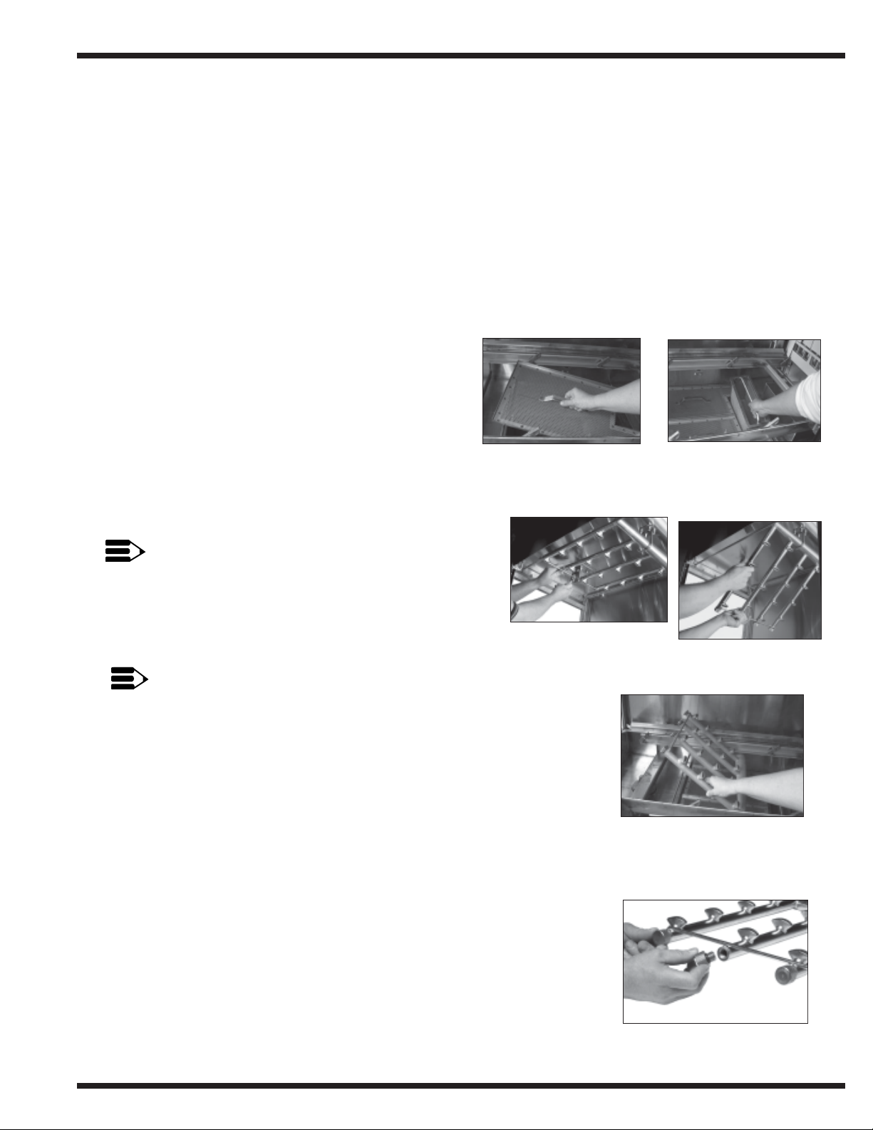
2. Pull drain lever(s) to drain water. Remove scrap
screens and scrap baskets (internal and
external ,if applicable). Clean inside of the
tanks and flush with clean water. Back flush the
scrap screens until clean. (See Figs 2 & 3)
Figure 2-
Scrap Screen Removal
Figure 3-
Scrap Basket Removal
NOTE:
DO NOT strike or bang screens or baskets against
solid objects
3. Remove the spray pipes (Figs. 4-6) Remove the
end cap from each spray pipe (Fig. 7). Flush the
pipes and nozzles until clean.
NOTE:
DO NOT strike or bang wash pipes against solid objects
Replace the end caps and verify the rubber o-rings are in place.
Reinstall the spray pipes.
4. Remove and clean the curtains. Hang them off the dishtable and
allow them to dry at the end of the day.
5. Leave the doors open between operations, allowing the machine to
dry.
6. Verify that the final rinse nozzles are clean and free of any internal
hard water deposits. If necessary, clean the nozzle orifices with a
small paper clip. Consult your chemical supplier for proper use
and the kind of deliming chemicals needed.
7. Report any unusual conditions to your supervisor.
Figure 4-
Unhooking Upper Arm
Figure 5-
Upper Wash Arm
Removal
Figure 6-
Lower Wash Arm Removal
• As Required
1. Check the temperature and pressure gauge readings
2. Inspect the machine and check the pump motor for any leaks
around the shaft
3. Check the chemical supplies and refill as necessary.
PDF compression, OCR, web optimization using a watermarked evaluation copy of CVISION PDFCompressorPDF compression, OCR, web optimization using a watermarked evaluation copy of CVISION PDFCompressor
Figure 7-
End Cap Removal
9

MAINTENANCE
MAINTENANCE (CONT’)
• Weekly
1. Inspect all water lines for leaks and tighten at joints if required.
2. Clean all of the detergent residue from the exterior of the machine.
3. Check the drain/overflow tube for any leaks,
4. Clean the accumulated scale from the heating element.
5. Remove and closely inspect each spray arm for blockage.
6. Straighten a small paper clip to clear each final rinse nozzle.
7. Inspect the pawl bar and drive assembly for wear and freedom of travel.
8. Check the float switch(es) in the tank(s) for freedom of travel.
9. Check the idle pump(s) and final rinse lever for freedom of travel.
Deliming
Your dishwasher should be delimed regularly as required. This will depend on the mineral
content of your water.
Inspect your machines interior for lime deposits. If required, consult your chemical supplier
for the proper type and procedures on deliming agents.
If you have a chemical sanitizing model 44 LT or 66 LT PW, CAREFULLY follow the
procedure below before deliming:
DANGER:
!
Deliming solution, rinse agents or other acids must not come in contact with
household bleach (sodium hypochlorite) or any chemicals containing chlorine,
iodine, bromine, or fluorine. Mixing may cause hazardous gases to form. Consult
your chemical supplier.
1. Remove the suction tube assembly from the bleach container and place it as close as
possible to the floor. Place a catch pan underneath it.
2. Cycle the machine approximately six times to purge the lines of the bleach.
3. Proceed with the deliming procedures.
PDF compression, OCR, web optimization using a watermarked evaluation copy of CVISION PDFCompressorPDF compression, OCR, web optimization using a watermarked evaluation copy of CVISION PDFCompressor
10
ELECTRICAL SERVICE
ELECTRICAL SERVICE
Fuse Blocks - 12OVAC Control Voltage
Fuse Blocks - 120VAC Control Voltage
Two fuse blocks, located in the center of the front of the main control cabinet,
Two fuse blocks, located in the center of the front of the main control cabinet,
protect the main control transformer. Each fuse block holds one fuse. The fuses
protect the main control transformer. Each fuse block holds one fuse. The fuses
are marked 1FU and 2FU on the electrical schematic.
are marked 1FU and 2FU on the electrical schematic.
To replace the fuse:
To re pla c e t he fuse :
Disconnect the power to the machine at the main service switch.
• Disconnect the power to the machine at the main service switch.
• Remove the fuse and replace it.
Remove the fuse and replace it.
• Turn the main power on.
Turn the main power on.
• If the fuse blows again, DO NOT INCREASE THE FUSE SIZE.
If the fuse blows again, DO NOT INCREASE THE FUSE SIZE.
• DETERMINE THE CAUSE OF THE OVERLOAD.
DETERMINE THE CAUSE OF THE OVERLOAD.
Fig. 5 shows the fuses and fuse blocks.
Fig. 5 shows the fuses and fuse blocks.
ELECTRICAL SERVICE
ELECTRICAL SERVICE
Figure 8-
Figure 8-
Fuse Blocks
Fuse Blocks
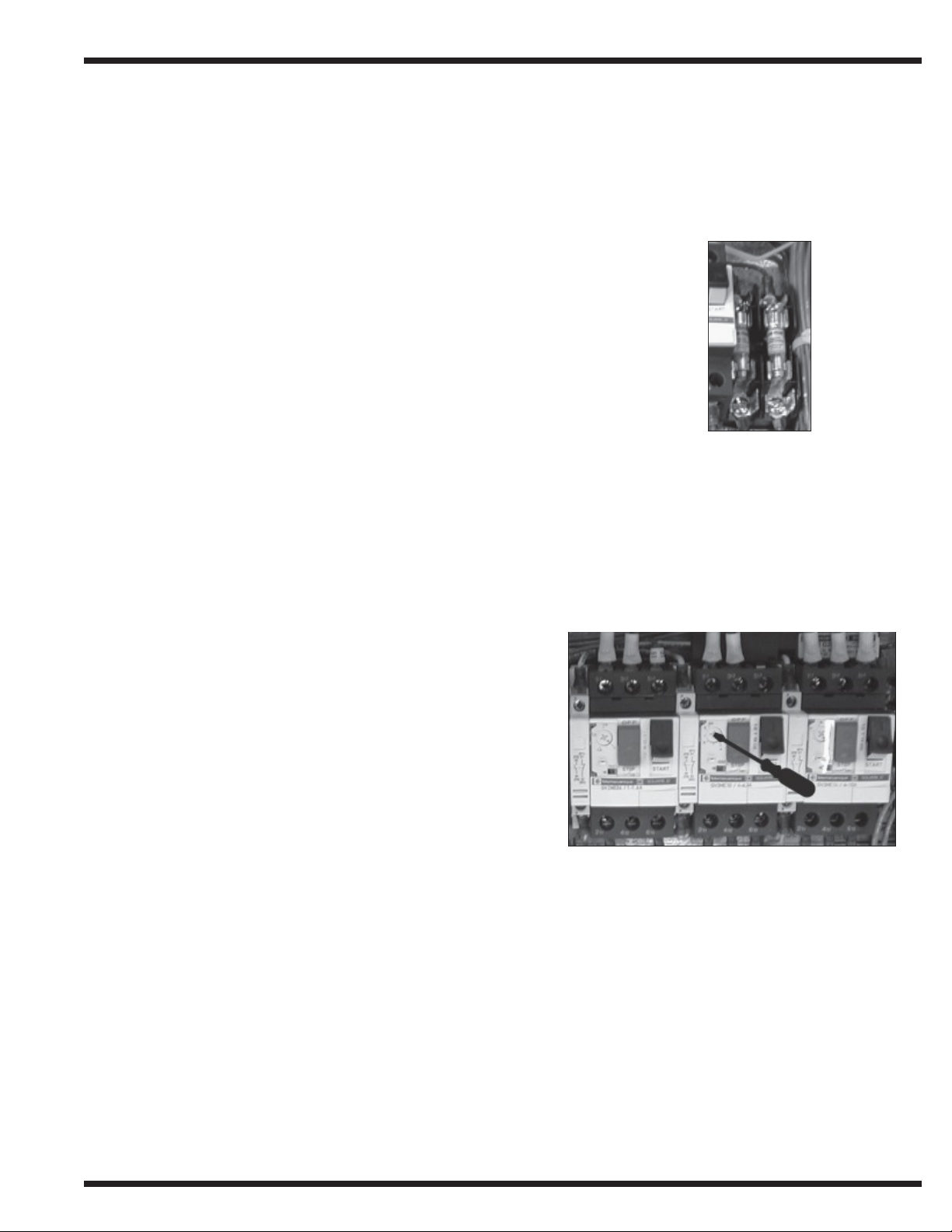
Motor Overloads
Motor Overloads
Motor overloads are located to the left of the fuse block inside the control cabinet. Each
Motor overloads are located to the left of the fuse block inside the control cabinet. Each
motor has
motor has
one overload to protect it from line voltage electrical overloads. In addition, an auxiliary set
one overload to protect it from line voltage electrical overloads. In addition, an auxiliary set
of switch contacts is attaches to the overload. The switch contacts disconnect 12OVAC
of switch contacts is attaches to the overload. The switch contacts disconnect 120VAC
power to the motor contactor coils in the event of an overload condition. Refer to Fig.6.
power to the motor contactor coils in the event of an overload condition. Refer to Fig.6.
Note the Switch Lever on the Overload
Not e t he Sw it c h Lever on t he Ove r load
• If the red OFF switch lever is down with the
If the red OFF switch lever is down with the
"OFF" showing then the overload has tripped
“OFF” showing then the overload has tripped
on an overload.
on an overload.
To Reset the Motor Overload:
To Rese t t he Motor Ove r loa d:
Push the start switch down with "ON" showing.
• Push the start switch down with “ON” showing.
• Run the dishwasher and test the AMP draw of the
Run the dishwasher and test the AMP draw of the
motor in question. If the motor checks ok then there
motor in question. If the motor checks ok then there
may be a wiring problem or the overload may be
may be a wiring problem or the overload may be
defective.
defective.
To Replace a Motor Overload:
To Repla c e a M otor Over loa d:
• Disconnect the wires to the overload.
Disconnect the wires to the overload.
Figure 9-
Figure 9-
Motor Overload
Motor Overload
• Pull forward and lift out.
Pull forward and lift out.
• Snap the new overload into place and reconnect the wires.
Snap the new overload into place and reconnect the wires.
To Adjust the Overload Setting:
To Adjust the Ove r loa d Set t ing:
The screwdriver in Fig. 6 is positioned to adjust the motor overload AMP setting.
The screwdriver in Fig. 6 is positioned to adjust the motor overload AMP setting.
• Read the FLA motor amps that applies for the machine voltage
Read the FLA motor amps that applies for the machine voltage
on the Motor Nameplate.
on the Motor Nameplate.
• Flip up the plastic cover. Turn the setting to match the nameplate FLA.
Flip up the plastic cover. Turn the setting to match the nameplate FLA.
PDF compression, OCR, web optimization using a watermarked evaluation copy of CVISION PDFCompressorPDF compression, OCR, web optimization using a watermarked evaluation copy of CVISION PDFCompressor
11

ELECTRICAL SERVICE
ELECTRICAL SERVICE
ELECTRICAL SERVICE (CONT')
ELECTRICAL SERVICE (CONT’)
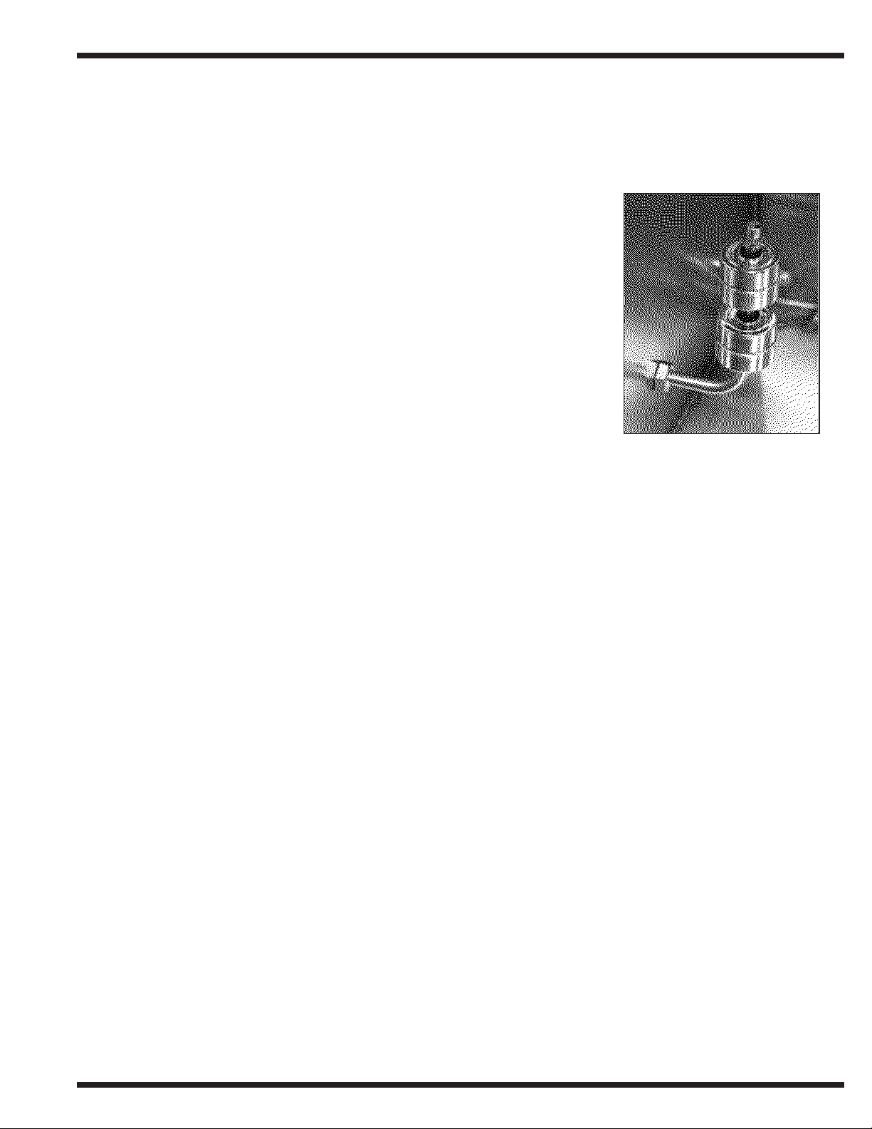
Pump Timer
Pump Timer
The automatic timer located in the left center of the control cabinet
The automatic timer located in the left center of the control cabinet
is preset at the manufacturer.
is preset at the manufacturer.
The Pump Timer controls the amount of time that the pump(s) and the
The Pump Timer controls the amount of time that the pump(s) and the
drive motor will run after the last rack enters the load end of the
drive motor will run after the last rack enters the load end of the
dishwasher tunnel.
dishwasher tunnel.
The Pump Timer is an OFF DELAY timer. One timer controls all
The Pump Timer is an OFF DELAY timer. One timer controls all
pumps no matter what the model it may be. Cycle time is 90 seconds.
pumps no matter what the model it may be. Cycle time is 90 seconds.
To Replace a Timer:
To Replace a Timer:
Disconnect the power to the machine at the main service switch.
• Disconnect the power to the machine at the main service switch.
Remove the wires connected to the timer. Remove the screw in
• Remove the wires connected to the timer. Remove the screw in
the center of the timer.
the center of the timer.
Figure 10-
Figure 10-
Pump Timer
Pump Timer
Remove the defective timer and install the replacement.
• Remove the defective timer and install the replacement.
Reinstall the screw and reinsert the wires.
• Reinstall the screw and reinsert the wires.
Operation Sequence:
Operation Sequence:
• A dishrack entering the machine contacts the idle pump switch lever.
A dishrack entering the machine contacts the idle pump switch lever.
• The contacts of the idle pump switch open, de-energizing control relay 1CR.
The contacts of the idle pump switch open, dc-energizing control relay 1CR.
• Normally closed contacts of 1CR close and apply a signal to pump timer. The timer
Normally closed contacts of 1CR close and apply a signal to pump timer. The timer
contacts close turning on the pump(s) and drive motor.
contacts close turning on the pump(s) and drive motor.
• The dishrack moves off the idle pump switch lever and the switch contacts close.
The dishrack moves off the idle pump switch lever and the switch contacts close.
• 1CR energizes and the notmally closed contacts open removing the signal from the
1CR energizes and the notmally closed contacts open removing the signal from the
pump timer.
pump timer.
• The pump timer begins to time down for its 90 seconds time setting.
The pump timer begins to time down for its 90 seconds time setting.
• The timer is reset each time the idle pump switch is activated. If the timer is reset only
The timer is reset each time the idle pump switch is activated. If the timer is reset only
once it will time out and shut the pump(s) and drive motor off after the time delay.
once it will time out and shut the pump(s) and drive motor off after the time delay.
To Check the Pump Timer Setting:
To Check the Pump Timer Setting:
Use a stop watch to check the timing cycle.
Use a stop watch to check the timing cycle.
Turn the power on.
• Turn the power on.
Press the green lighted START pushbutton.
• Press the green lighted START pushbutton.
Place a rack in to the conveyor.
• Place a rack in to the conveyor.
When the rack enters the load end, the pump(s) and the drive motor will start.
• When the rack enters the load end, the pump(s) and the drive motor will start.
Start the stop watch when the rack clears the idle pump switch. Stop the stop watch
• Start the stop watch when the rack clears the idle pump switch. Stop the stop watch
when the machine stops. The lengthof the cycle should be 90 seconds +I 2 seconds.
when the machine stops. The lengthof the cycle should be 90 seconds +/- 2 seconds.
If the timer is not within this range replae the timer.
If the timer is not within this range replae the timer.
PDF compression, OCR, web optimization using a watermarked evaluation copy of CVISION PDFCompressorPDF compression, OCR, web optimization using a watermarked evaluation copy of CVISION PDFCompressor
12
ELECTRICAL SERVICE (CONT')
ELECTRICAL SERVICE (CONT’)
Automatic Fill/Low Water Heat Protection
Automatic Fill/Low Water Heat Protection
Dual Float Switches
Dua l Floa t Sw it c he s
Each tank contains a dual float switch (see Fig.8). The device consists
Each tank contains a dual float switch (see Fig.8). The device consists
of an angled stem containing two reed switches. Two stainless steel
of an angled stem containing two reed switches. Two stainless steel
ball floats, containing magnets, slide over the stem and are free to move
ball floats, containing magnets, slide over the stem and are free to move
up and down. When the float moves on the stem, it opens and closes the
up and down. When the float moves on the stem, it opens and closes the
associated reed switch inside the stem. The reed switches control
associated reed switch inside the stem. The reed switches control relays.
The relays control the automatic fill and heat for different parts of the
The relays control the automatic fill and heat for different parts of the
machine. The float switch(es) and their relay(s) operate on a 120V circuit.
machine. The float switch(es) and their relay(s) operate on a 120V circuit.
Circuit Explanation
Circ uit Ex plana t ion
Refer to the electrical schematic on your machine for a detailed
Refer to the electrical schematic on your machine for a detailed
description of the individual float(s), relay(s) and wiring.
description of the individual float(s), relay(s) and wiring.
Bottom Float and Reed Switch
Bot t om Floa t and Re e d Sw it c h
The bottom float controls the heat.
• The bottom float controls the heat.
When the bottom float is down, the bottom reed switch contacts are open.
• When the bottom float is down, the bottom reed switch contacts are open.
When the bottom float is up, the bottom reed switch contacts are closed.
• When the bottom float is up, the bottom reed switch contacts are closed.
relays.
ELECTRICAL SERVICE
ELECTRICAL SERVICE
Figure 11-
Figure 11-
Dual Float Switch
Dual Float Switch
Top Float and Reed Switch
Top Float a nd Re e d Sw it ch
The top float controls a fill valve, which controls the water level.
• The top float controls a fill valve, which controls the water level.
When the top float is down, the top reed switch contacts are open.
• When the top float is down, the top reed switch contacts are open.
When the top float is up, the top reed switch contacts are closed.
• When the top float is up, the top reed switch contacts are closed.
Initial Fill
Init ia l Fill
• When the tank is completely empty, both floats are down and their reed switch contacts
When the tank is completely empty, both floats are down and their reed switch contacts
are open.
are open.
The control relay for the float switch is dc-energized.
• The control relay for the float switch is de-energized.
The fill valve for the tank is energized and the tank begins to fill with water.
• The fill valve for the tank is energized and the tank begins to fill with water.
As the water level in the tank rises, the bottom float begins to move up.
• As the water level in the tank rises, the bottom float begins to move up.
When the bottom float is completely up, its reed switch contacts close.
• When the bottom float is completely up, its reed switch contacts close.
This prepares the heat circuit, but the heat DOES NOT energize at this time.
• This prepares the heat circuit, but the heat DOES NOT energize at this time.
The tank continues to fill until the top float is completely up.
• The tank continues to fill until the top float is completely up.
The top float's reed switch contacts close. Its control relay energizes.
• The top float’s reed switch contacts close. Its control relay energizes.
The fill valve dc-energizes.
• The fill valve de-energizes.
The heat circuit energizes through the contacts of the control relay.
• The heat circuit energizes through the contacts of the control relay.
During Normal Operation
During N or mal Ope ra t ion
If the water level in a tank falls below the level of the top float, the top float moves down
• If the water level in a tank falls below the level of the top float, the top float moves down
and its reed switch contacts open.
and its reed switch contacts open.
When the water level falls below the level of the bottom float, the bottom float moves
• When the water level falls below the level of the bottom float, the bottom float moves
down and its reed switch opens.
down and its reed switch opens.
The control relay dc-energizes. The fill and rinse valve energizes and refills the tank.
• The control relay de-energizes. The fill and rinse valve energizes and refills the tank.
The heat circuit will dc-energize until the water level in the tank raises the top float
• The heat circuit will de-energize until the water level in the tank raises the top float
again.
again.
The bottom float keeps the heat circuit ready as long as the water level is above the level
• The bottom float keeps the heat circuit ready as long as the water level is above the level
of the bottom float.
of the bottom float.
PDF compression, OCR, web optimization using a watermarked evaluation copy of CVISION PDFCompressorPDF compression, OCR, web optimization using a watermarked evaluation copy of CVISION PDFCompressor
13
ELECTRICAL SERVICE
ELECTRICAL SERVICE
ELECTRICAL SERVICE (CONT')
ELECTRICAL SERVICE (CONT’)
Thermostat Locations and Adjustments
Thermostat Locations and Adjustments
Electric tank heat is controlled by two thermostats.
Electric tank heat is controlled by two thermostats.
The control thermostat which regulates the electric tank heat
1. The control thermostat which regulates the electric tank heat
temperature.
temperature.
The high limit thermostat which protects the tank from
2. The high limit thermostat which protects the tank from
overheating.
overheating.
Location
Loc a t ion
Both thermostats are located on the front of the tank, inside of a
Both thermostats are located on the front of the tank, inside of a
heater box enclosed in a stainless steel panel, behind the front
heater box enclosed in a stainless steel panel, behind the front
access panel.
access panel.
Adjust m e nt
Adjustment
The Control Thermostat has an adjustment screw.
The Control Thermostat has an adjustment screw.
High Limit
Thermostat
Figure 12-
Figure 12-
Tank Heat Thermostats
Tank Heat Thermostats
The thermostat is wire Normally Closed.
• The thermostat is wire Normally Closed.
Turn the adjustment screw clockwise to increase the
• Turn the adjustment screw clockwise to increase the
temperature in the tank and counterclockwise to decrease
temperature in the tank and counterclockwise to decrease
the temperature in the tank.
the temperature in the tank.
The High Limit Thermostat is not adjustable. It contains a red
The High Limit Thermostat is not adjustable. It contains a red
reset button on its center.
reset button on its center.
The red button pops out if the temperature in the tank
• The red button pops out if the temperature in the tank
exceeds 210°F/99°C.
exceeds 210°F/99°C.
Press the red button in to reset the high limit
• Press the red button in to reset the high limit.
DETERMINE THE CAUSE OF THE HIGH
DETERMINE THE CAUSE OF THE HIGH
TEMPERATURE CONDITION.
TEMPERATURE CONDITION.
Refer to Fig 13 & Fig 14
Refer to Fig 13 & Fig 14
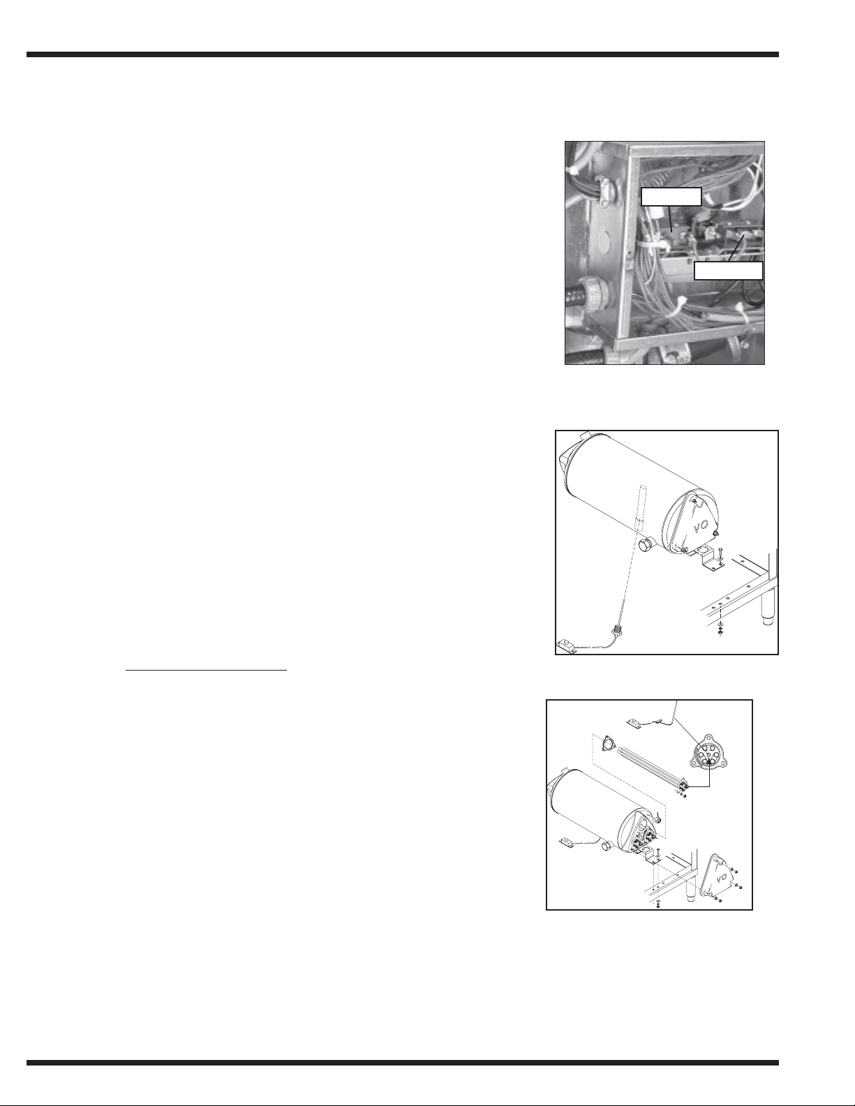
Electric Booster Heat is controlled by two thermostats.
Electric Booster Heat is controlled by two thermostats.
The control thermostat regulates the temperature.
1. The control thermostat regulates the temperature.
The high limit thermostat protects the booster from
2. The high limit thermostat protects the booster from
overheating.
overheating.
Each tank has a control and a high limit thermostat.
3. Each tank has a control and a high limit thermostat.
Loc a t ion:
Location:
The control thermostat is in the junction box on the wash tank.
The control thermostat is in the junction box on the wash tank.
Figure 13-
Figure 13-
Booster Thermostat Location
Booster Thermostat Location
Insert thermostat probe
into tube in center
of element
The thermostat is wire Normally Closed.
• The thermostat is wire Normally Closed.
Turn the adjustment screw clockwise to increase the
• Turn the adjustment screw clockwise to increase the
booster tank temperature and counterclockwise to
booster tank temperature and counterclockwise to
decrease the booster tank temperature.
decrease the booster tank temperature.
The high limit thermostat is also in the junction box on the
The high limit thermostat is also in the junction box on the
wash tank.
wash tank.
A red button that pops out when the temperature exceeds 210°F199°C.
• A red button that pops out when the temperature exceeds 210°F/99°C.
Press the red reset button to reset the high limit
• Press the red reset button to reset the high limit.
Determine the cause of the high limit temperature condition.
Determine the cause of the high limit temperature condition.
PDF compression, OCR, web optimization using a watermarked evaluation copy of CVISION PDFCompressorPDF compression, OCR, web optimization using a watermarked evaluation copy of CVISION PDFCompressor
14
Booster High Limit Thermostat
Booster High Limit Thermostat
Figure 14-
Figure 14-

ELECTRICAL SERVICE
ELECTRICAL SERVICE (CONT’)
Heater Element Wiring-Booster Tank and Wash Tank Heater
Elements
Refer to the illustrations and follow the steps below to properly install terminal jumpers and to
make line power connections to a replacement element.
Step 1. Hold the element assembly with the calrod coils facing toward you.
Step 2. Match your element coils to Configuration A or B
Step 3. Rotate your element coils to match the correct configuration.
Step 4. Flip the element over and match your element to the correct terminal configuration.
Step 5. Install the terminal jumpers according to the illustrations for your voltage requirement.
Step 6. Install the element and make your line connections 1L1, 1L2 or 1L3 per the
illustration.
Step 7. If installing a booster element (that requires the limiting thermostat), the limiting
thermostat should be inserted into the center of element. Thermostat should bottom
out in the tube approximately 12" deep. The exposed capillary leads should be routed
under the booster cover and fastened to the stud in the upper right side of the booster
can with the clip and nut. See Figure 43 Electric Booster in Replacement Parts section.
Configuration A
Booster tank element
View of calrod coils
Configuration B
Wash tank element
View of calrod coils
1L1
1L2
208V/1 Phase
1L1
1L2
208V/1 Phase
Terminal Connections
1L1
1L3
1L2
208-240V/3 Phase
Delta Connection
1L1
1L2
480V/3 Phase
575V/3 Phase
Delta Connection
Terminal Connections
1L1
1L2
1L3
208-240V/3 Phase
Delta Connection
1L1
1L2
1L3
480V/3 Phase
575V/3 Phase
Delta Connection
view of element
1L3
view of element
1L2
1L1
1L3
208-240V/3 Phase
Wye Connection for
380-415V/3 Phase
1L3
1L1
1L2
208-240V/3 Phase
Wye Connection for
380-415V/3 Phase
PDF compression, OCR, web optimization using a watermarked evaluation copy of CVISION PDFCompressorPDF compression, OCR, web optimization using a watermarked evaluation copy of CVISION PDFCompressor
15

ELECTRICAL SERVICE
ELECTRICAL SERVICE (CONT’)
Electric Booster Heater- Element Installation
Champion built-in boosters are constructed of stainless steel and have locations for three
electric booster heater elements. There are three booster configurations for the rack conveyor models:
40°F/22°C rise booster (minimum of 140°F/60°C incoming water)
60°F/34°C rise booster (minimum of 120°F/49°C to 140°F/60° incoming water)
70°F/39°C rise booster (minimum of 110°F/43°C incoming water)
The canisters and total Kw ratings of the booster assemblies are determined by the model
number of the machine and the minimum temperature of the incoming water supply that the
end user is able to supply to the machine. Machines can be supplied with 40°F/22°C rise
booster or 60°F/34°C rise booster which use only one canister (nested boosted) with separate electrical connections. The 70°F/39°C rise models use two canisters in the booster
assemblies, these also have separate electrical connections.
Water Saver (44 WS and 66 WS PW) models are supplied in only 40°F/22°C or 70°/39°c
rise booster assemblies. These are single canister units in either option and are not separate
electrical connections.
PDF compression, OCR, web optimization using a watermarked evaluation copy of CVISION PDFCompressorPDF compression, OCR, web optimization using a watermarked evaluation copy of CVISION PDFCompressor
16

ELECTRICAL SERVICE (CONT’)
Motors-Pump
Voltage: Standard motors are multi-voltage
Low voltage: 208-230VAC
High voltage: 460VAC or 575VAC
Phase: Motors may be single or three phase.
Wiring Conne c t ions
Refer to the diagrams below for three phase motor lead wiring.
ELECTRICAL SERVICE
Low voltage
208-230V/3PH
654
High voltage
460V/3PH
654
575V/3PH
Only
321
987
321
LINE
Refer to diagram at right for single phase motor lead wiring.
987
321
LINE
Low voltage
LINE
L1
3
4
J
2
8
208-230V/1PH
Only
Troubleshooting
Mot or w ill not r un
1. Check incoming power to control cabinet.
2. Check for tripped manual motor starter (overload) in control cabinet.
(Refer to Motor Overload service section for proper settings).
3. Check power at motor contactor.
Mot or runs hot a nd t rips m ot or st a r t e r over loa d
1. Check for proper voltage between L1-L2 or (L1-l2, L2-L3, L1-L3 for 3 phase).
2. Check FLA on motor leads L1, L2, (also L3 for 3 phase) using amp tester.
(Motor full load amp (FLA) ratings are stamped on motor nameplate).
Mot or Re place m e nt
1. Disconnect the power to the machine.
2. Disconnect the wires to the motor junction box.
3. Make note of the motor connections in order to phase the replacement correctly.
4. Install the new motor and check for proper rotation.
(Proper rotation is clockwise looking from at the rear of the motor).
5. Motor rotation can be reversed by switching L1 and L2 on three phase motors.
Single phase motor rotation cannot be reversed.
L2
LINE
LINE
PDF compression, OCR, web optimization using a watermarked evaluation copy of CVISION PDFCompressorPDF compression, OCR, web optimization using a watermarked evaluation copy of CVISION PDFCompressor
17
V
V
ELECTRICAL SERVICE
ELECTRICAL SERVICE (CONT’)
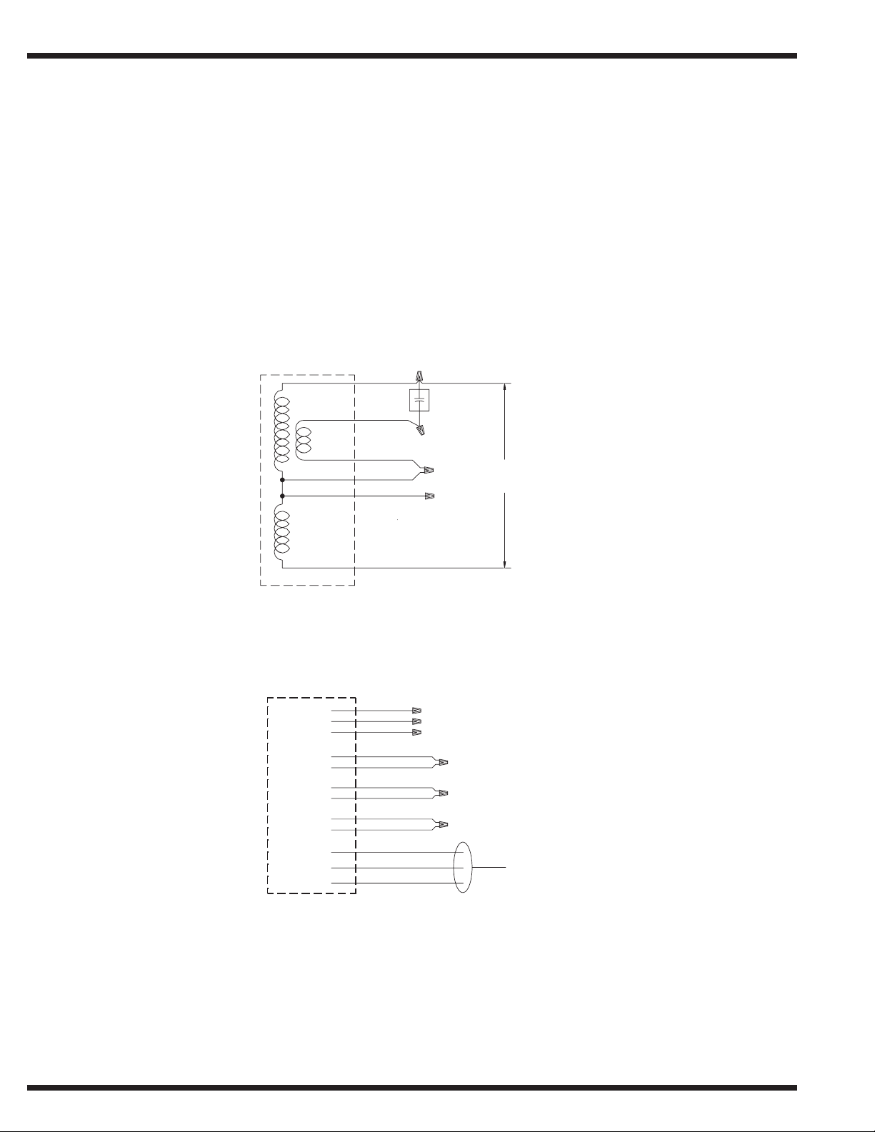
Motors-Drive
Voltage: Standard motors are multi-voltage
208-240V 1Phase Wiring Diagram
To reverse motor rotation interchange yellow and orange leads.
Low Voltage: 208-240VAC 1 Phase Only
High Voltage: 380/480/575VAC 3 Phase Only
Motor 1/6 HP
208/240V
Run
Winding
Start
Winding
White Wire
Orange Wire
Yellow WIre
Brown Wire
Black Wire
Capacitor
10MFD
370VAC
Connect 208/240
Power Here
Run X
Winding
Red Wire
380/480/575/V 3Phase Wiring Diagram
To reverse motor rotation interchange any two external connections.
Motor 1/6HP
380/480/575 Volt
P6 Orange Wire
P5 Tan Wire
P4 Blue Wire
T6 Purple Wire
T9 Brown Wire
T4 Yellow Wire
T7 Pink Wire
T5 Black Wire
T8 Red Wire
T3 Orange Wire
T1 Blue Wire
T2 Tan Wire
Connect 380/480/575
3 Phase
Power Here
Drive Interlock Switch
Drive interlock will activate when a jam has occured in the unit.
• When a jam occurs, the switch opens and the pump(s) and drive motor are then shut off,
similar to the reaction of pushing the red STOP pushbutton (the green light goes out
also).
• The switch will automatically reset when the jam is cleared. To restart/reset the machine
push the green START pushbutton and insert a loaded rack.
PDF compression, OCR, web optimization using a watermarked evaluation copy of CVISION PDFCompressorPDF compression, OCR, web optimization using a watermarked evaluation copy of CVISION PDFCompressor
18

REPLACEMENT PARTS
REPLACEMENT
PA R T S
PDF compression, OCR, web optimization using a watermarked evaluation copy of CVISION PDFCompressorPDF compression, OCR, web optimization using a watermarked evaluation copy of CVISION PDFCompressor
19

REPLACEMENT PARTS
5
6
Prior to S/N R3447
10
8
After S/N R3448
8
7
9
11
12
E
D
11
14
7
C
4
13
13
3
2
D
B
A
1
Figure 15- Prewash Panels, Doors and Miscellaneous
PDF compression, OCR, web optimization using a watermarked evaluation copy of CVISION PDFCompressorPDF compression, OCR, web optimization using a watermarked evaluation copy of CVISION PDFCompressor
20

REPLACEMENT PARTS
PREWASH PANELS, DOORS
AND MISCELLANEOUS
Fig. 15 Part
Item No. No. Part Description Qty
1 328977 Panel, Front Perimeter 22PW ...................................................... 1
1 328978 Panel, Front Perimeter 36PW ...................................................... 1
2 327857 Panel, 25" Prewash Perimeter ..................................................... 1
3 328030 Table Flange Support .................................................................. 1
4 328006 Support, 22 PW Rear Screen ...................................................... 1
5 108250 Rod Curtain 5/16 x 24-5/8......................................................... 1
6 108043 Curtain 24 x 13-1/4 ..................................................................... 1
7 206358 Rod, 22PW Door Catch (Prior to S/N R3447) .......................... 1
7 328909 Door Catch 22PW (After S/N R3448) ....................................... 1
8 327887 Bracket, Door Catch Mounting (Prior to S/N R3447) .............. 2
8 317345 Bracket, Door Catch (After S/N R3448) ................................... 2
9 100734 Bolt, 1/4-20 x 1/2 Hex Head ...................................................... 2
10 100141 Nut, Grip 1/4-20 SST .................................................................. 2
11 113691 Guide, U-channel Door............................................................... 2
12 327952 Door, 22PW .................................................................................. 1
--- 111026 Magnet, Door (Not Shown) ........................................................ 1
--- 113719 Switch, Reed Aleph (Not Shown) .............................................. 1
13 108966 Door Handle ................................................................................. 2
14 313359 Bracket, Door Stop ...................................................................... 1
A Panel Fasteners (Qty per Panel)
100007 Screw 10-32 x 3/8 Truss Head ...................................................... 4
B Table Flange Fasteners
C Screen Support Fasteners
Bolt
Washer
Nut
D Door and Scrap Basket Handle Fasteners (Qty per Handle)
100073 Screw1/4-20 x 1/2 Truss Head ...................................................... 2
E Door Guide Fasteners (Qty per Guide)
113486 Screw 8-32 x 5/8 Flat Head SST ................................................ 6
112431 Rivnut 8/32 Steel Zinc Plated ..................................................... 6
PDF compression, OCR, web optimization using a watermarked evaluation copy of CVISION PDFCompressorPDF compression, OCR, web optimization using a watermarked evaluation copy of CVISION PDFCompressor
21

REPLACEMENT PARTS
Prior to S/N R3447
9
7
4
8
After S/N R3448
7
13
10
12
16
10
B
11
C
5
6
15
3
A
1
2
PDF compression, OCR, web optimization using a watermarked evaluation copy of CVISION PDFCompressorPDF compression, OCR, web optimization using a watermarked evaluation copy of CVISION PDFCompressor
22
A
Figure 16- Single Tank Doors, Panels
and Miscellaneous
 Loading...