

Page 1
Belt Drive Battery Backup Garage Door Opener
HD920EV • 349544 • WD962KEV • WD962KPEV
Write down the following information for
future reference:
Model Number:
Serial Number:
Date of Purchase:
Models
FOR RESIDENTIAL USE ONLY
■ Please read this manual and the enclosed safety materials carefully!
■ Fasten the manual near the garage door after installation.
■ The door WILL NOT CLOSE unless the Protector System
aligned.
■ Periodic checks of the garage door opener are required to ensure safe operation.
■ The model number label is located on the left side panel of your garage door opener.
■ This garage door opener is compatible with MyQ™ and Security✚
■ DO NOT enable the Timer-to-Close feature if you are installing the garage door opener
on a one-piece door. The Timer-to-Close is to be used ONLY with sectional doors.
.
®
is connected and properly
2.0™ accessories.
www.chamberlain.com
The Chamberlain Group, Inc.
Elmhurst, Illinois 60126-1196
845 Larch Avenue
CONTENTS
Preparation . . . . . . . . . . . . . . . .2-5
Assembly . . . . . . . . . . . . . . . . 6-10
Installation . . . . . . . . . . . . . . 11-20
Install the Door Control. . . . . . 21-23
Install the Protector System
Power. . . . . . . . . . . . . . . . . . 27-28
Adjustments . . . . . . . . . . . . . 29-31
Battery Backup. . . . . . . . . . . . 32-33
Operation . . . . . . . . . . . . . . . . . 34
Features . . . . . . . . . . . . . . . . . . 35
Door Control . . . . . . . . . . . . . 36-38
Remote Control . . . . . . . . . . . 39-40
To Erase the Memory . . . . . . . . . 40
To Open the Door Manually . . . . . 41
Maintenance . . . . . . . . . . . . . . . 42
Troubleshooting. . . . . . . . . . . 43-44
Repair Parts . . . . . . . . . . . . . 45-46
Accessories. . . . . . . . . . . . . . . . 47
Warranty. . . . . . . . . . . . . . . . . . 48
®
. . 23-26
Page 2
Torsion Spring
Extensi
on Spring
OR
Preparation
Safety Symbol and Signal Word Review
Thisgarage door opener has been designed and
tested tooffersafeservice provided it is installed,
operated, maintained and tested in strict
accordance with the instructionsand warnings
contained in thismanual.
When you see these Safety Symbols and Signal
Words on the following pages,they will alert you
to the possibilityof serious injury or death if you
do notcomplywith the warnings that accompany
them.The hazard maycome fromsomething
mechanical or fromelectricshock. Read the
warnings carefully.
Mechanical
Electrical
When you see this Signal Word on the following
pages, it will alertyou to the possibilityofdamage
to your garage door and/or thegarage door
opener if you do not comply with the cautionary
statementsthataccompanyit.Read them
carefully.
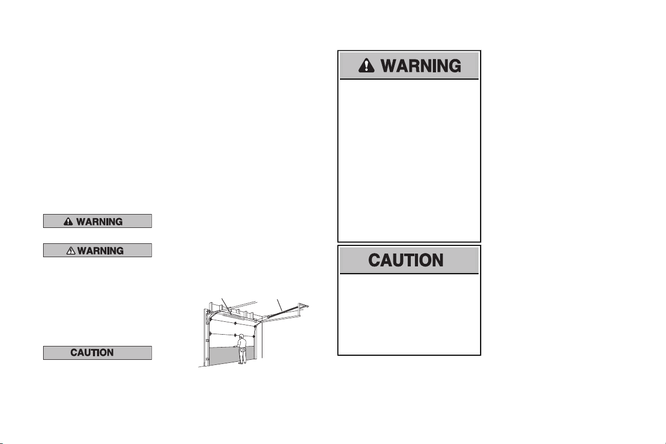
Check the Door
1. Disable locksand removeany ropes
connected to the garage door.
2. Liftthe door halfwayup. Release the
door. If balanced, it should stayin
place, supported entirelyby itssprings.
3. Raise and lower the door to check for
binding or sticking.Ifyour door binds,
sticks,or is out ofbalance, call a trained
door systemstechnician.
4. Checkthe seal on the bottom of the
door. Anygap between the floor and
the bottom of the door mustnot exceed
1/4 inch (6 mm).Otherwise,the safety
reversal system may not workproperly.
5. The opener should be installed above
the center of thedoor. If there isa
torsion spring or center bearing plate
in the wayofthe header bracket,itmay
be installed within 4 feet(1.2 m) to the
leftor rightofthe door center.
See page 13.
To prevent possible SERIOUS NJURYor
DEATH:
• ALWAYS call a trained door systems
technician if garage door binds, sticks,or
is out of balance.An unbalanced garage
door mayNOTreverse when required.
• NEVER try to loosen, move or adjust
garage door, door springs, cables,
pulleys,bracketsor their hardware,
ALLof which are under
EXTREMEtension.
• Disable ALLlocksand removeALLropes
connected to garage door BEFORE
installation and operating garage door
opener to avoid entanglement.
To prevent damage to garage door and
opener:
• ALWAYS disable locks BEFORE
installing and operating the opener.
• ONLY operate garage door opener at
120 V,60 Hz to avoidmalfunction and
damage.
2
Page 3

2
1
3/16
7/16
1/2
5/32
5/16
5/8
9/16
1/4
7/16
Preparation
üAdditional items you may need:
Survey your garage area to see ifyou will need
any of the following items:
(2) 2X4 PIECES OFWOOD
q
Maybe usedto fastenthe header bracketto
the structural supports.Alsoused to position
the garage door opener during installation
and fortesting thesafety reversing sensors.
SUPPORT BRACKET AND FASTENING
q
HARDWARE
Mustbe used ifyou have a finished ceiling in
your garage.
EXTENSION BRACKETS (MODEL
q
41A5281) OR WOOD BLOCKS
Depending upon garage construction,
extension bracketsor wood blocksmaybe
needed to install the safety reversing sensor.
FASTENING HARDWARE
q
Alternate floor mounting of the safety
reversing sensor will require hardware not
provided.
OUTSIDEQUICKRELEASE
q
(MODEL7702CB)
Required fora garage with NO access door.
DOOR REINFORCEMENT
q
Required ifyou have a lightweight steel,
aluminum, fiberglass or glasspanel door.
RAIL EXTENSION KIT
q
Required ifyour garage door is more than 7
feet(2.13 m) high.
Tools Needed
3
Page 4
N
A
B
C
H
K
J
O
I
D
E
F
G
L
M
P
OR
Preparation
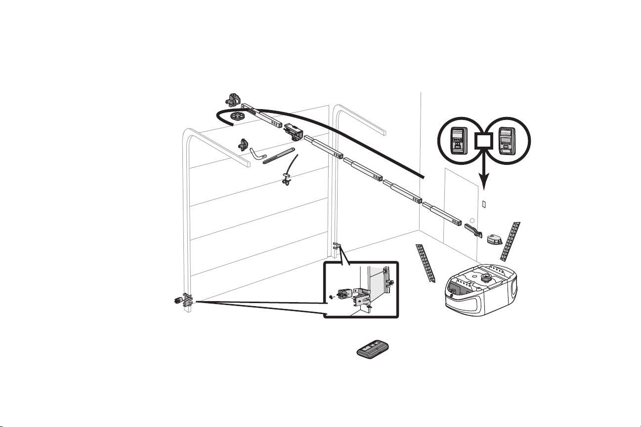
Carton Inventory
Your garage door opener is packaged in one carton which contains the motor unit and all parts illustrated below.Accessories vary depending on the garage door opener model purchased.Depending on your
model, other accessories may be included with your garage door opener. Instructions for these accessorieswill be attached tothe accessory and are not included in this manual. If anything ismissing, carefully
checkthe packing material. Parts may be stuck in the foam.Hardware for assembly and installation is shown on the next page.Save the carton and packing material until the installation and adjustmentis
complete.The images throughoutthismanual are for reference only and your productmay lookdifferent.
A. Header bracket
B. Pulley
C. Door bracket
D. Curved door arm
E. Straight door arm
(Packaged inside rail section)
F. Trolley
NOTE: Be sure to assemble the trolley
before sliding onto rail.
G. Emergency release ropeand handle
H. Rail (1front and4 center sections)
I. Hanging brackets (2)
(Packaged inside rail section)
J. Garage door opener
K. Sprocket cover and screws
L. “U” bracket
M. Belt
N. Door control (Motion-Detecting Control
Panel or Smart Control Panel®)
O. Remote control
P. The Protector System
Safetyreversingsensors with2 conductor
white and white/black wire attached:
SendingSensor (1), Receiving Sensor (1),
andSafety Sensor Brackets (2)
NOTSHOWN
White andred/white wire
Owner's manual
®
4
Page 5
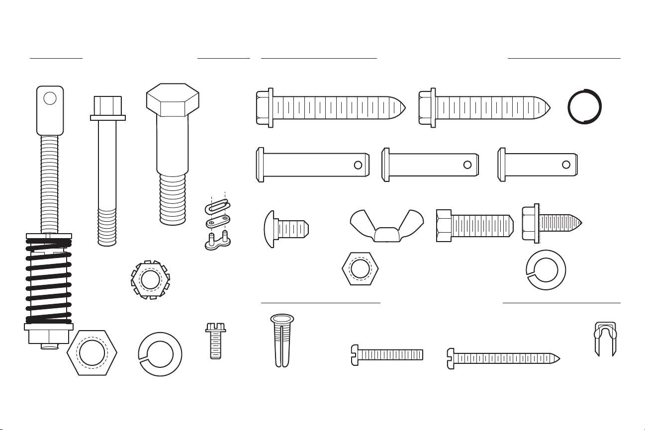
Carton Inventory
H9
Hex Screw #8x3/8" (3)
(packed with the
sprocket cover)
H2
Bolt
1/4"-20x1-3/4" (2)
H4
Lock Nut 1/4"-20 (2)
H3
Bolt
H6
Nut 3/8"
H7
Lock Washer 3/8"
H5
Master Link
H8
Spring
Trolley Nut
H12
Clevis Pin 5/16"x1-1/2"
H19
Ring Fastener (3)
H15
Hex Bolt 5/16"-18x7/8" (4)
H21
Lock Washer 5/16"-18 (7)
H20
Nut 5/16"-18 (8)
H16
Self-Threading Screw
1/4"-14x5/8" (2)
H14
Clevis Pin 5/16"x1"
H13
Clevis Pin 5/16"x1-1/4"
H17
Carriage Bolt 1/4"-20x1/2" (2)
H18
Wing Nut 1/4"-20 (2)
ASSEMBLY HARDWARE INSTALLATION HARDWARE
Screw 6ABx1-1/2" (2)
Drywall Anchors (2)
Screw 6-32x1" (2)
DOOR CONTROL HARDWARE
Insulated
Staples
H11
Lag Screw 5/16"-9x1-5/8" (2)
H10
Lag Screw 5/16"-18x1-7/8" (2)
H1
Threaded
Shaft
with
Preparation
5
Page 6
Trolley
To garage
door opener
Wear Pads
Inner Trolley
Outer Trolley
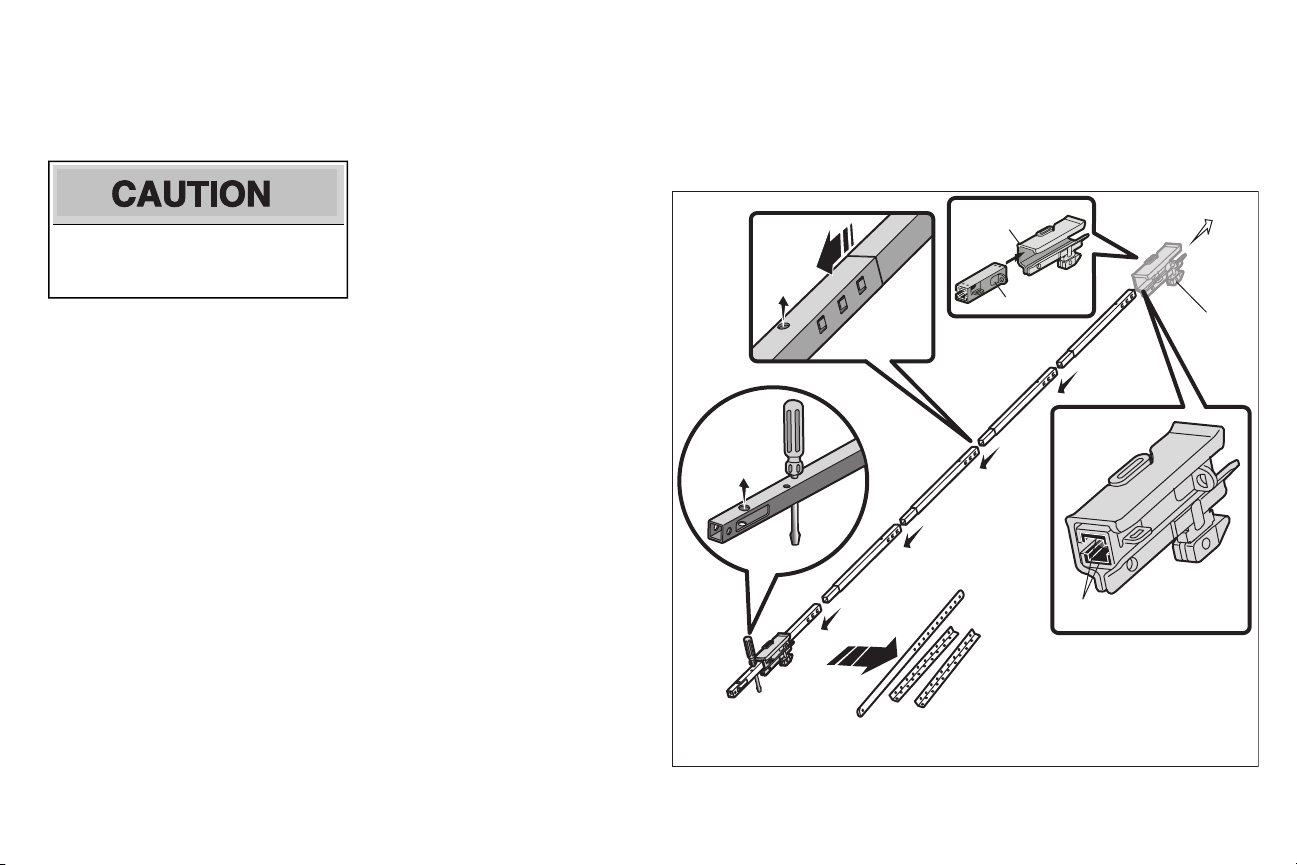
Assembly
1 Assemble the rail and trolley
To prevent NJURY frompinching, keep hands
and fingersawayfrom the joints while assembling
the rail.
To avoidinstallation difficulties, do not run the
garage door openeruntil instructed to do so.
1.1 Assemble the trolley bysliding the inner
trolley into the outer trolley.
1.2 Carefullyremove the straight door arm
and hanging brackets packaged inside the
frontrail.
1.3 Align the rails on a flat surface as shown.
The front rail has a cutout window near
the end. Make sure that the larger hole on
the front rail is facing up.
1.4 Slide the tapered end of each rail section
into the larger end of the rail section in
frontof it.The tabs along the side will lock
in place.All holes in the rail sections
should face up.
1.5 Inserta screwdriver into the hole shown
(thiswill temporarily keep the trolley from
sliding off the end of the rail).
1.6 Checktomake sure that the 4 plastic wear
pads are inside the inner trolley.If they are
missing checkall the packing material and
snap them backinto place.
1.7 Slide the trolley along the railtoward the
screwdriver asshown.
6
Page 7
(Mounted in the
garage door opener)
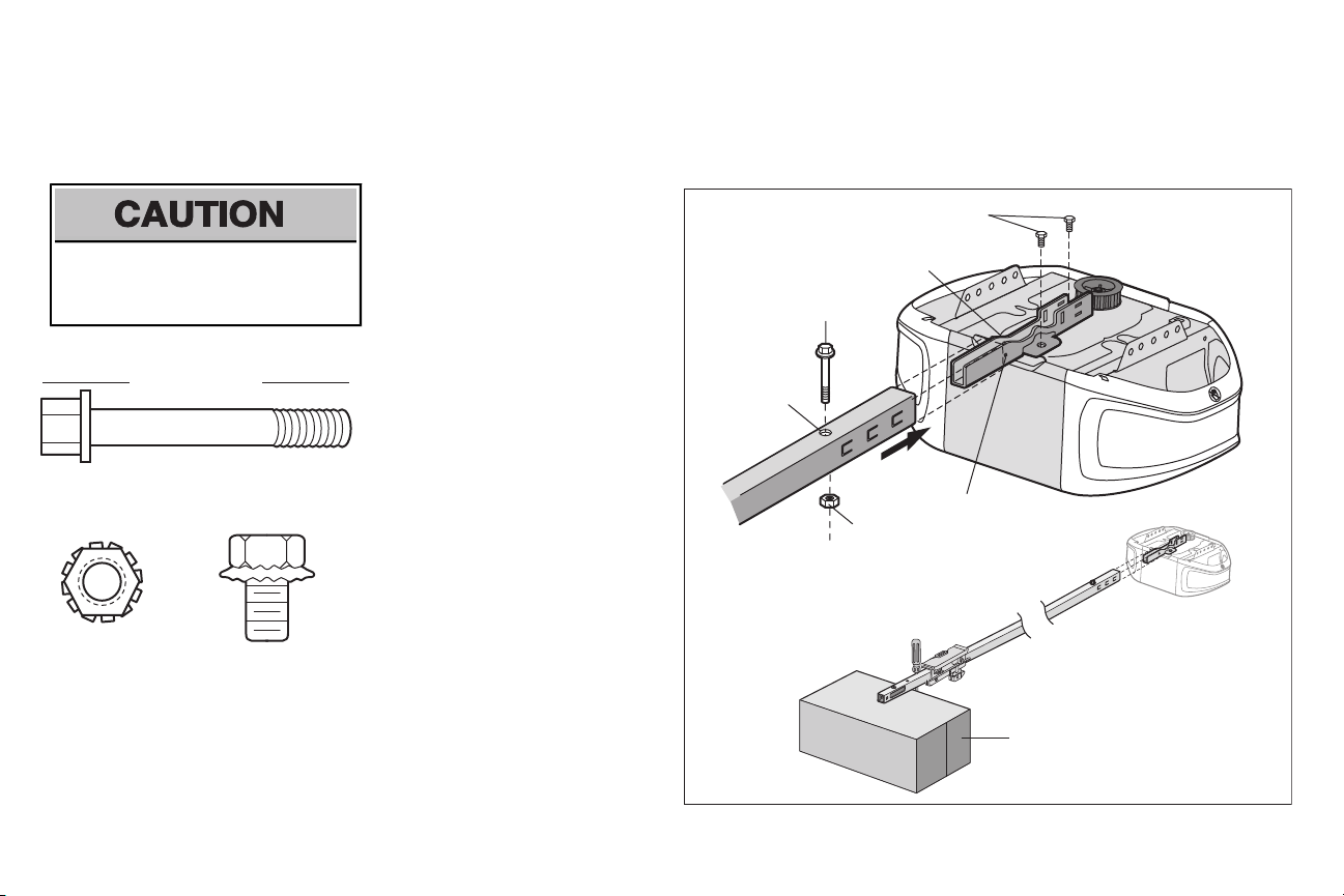
HARDWARE
H2
Bolt 1/4"-20x1-3/4"
H4
Lock Nut 1/4"-20
H2
“U” Bracket
Bolts
H4
SLIDE RAIL TO
STOPS ON TOP AND
SIDES
Cover
Protection
Bolt Hole
Carton
Assembly
2 Fasten the rail to the garage door opener
NOTE: ONLY use the bolts removed from the
garage door opener. Place the garage door
To avoid SERIOUSdamage to garage door
opener, useONLY those bolts/fasteners
mounted in the top of theopener.
opener on the packing material to prevent
scratching.
2.1 Insertthebolt (H2) into the hole on the
backend ofthe rail as shown.Tighten
securelywiththe lock nut (H4). Do not
overtighten.
2.2 Removethe two bolts from the top of the
garage door opener.
2.3 Place the “U” bracket,flatside down onto
the garage door opener and align the
brackethole with the bolt holes. Fasten the
“U” bracket with the previouslyremoved
bolts.
2.4 Prop up the end of the rail on the carton to
help align it with the “U” bracket.
2.5 Slide the rail onto the “U” bracket, until it
reaches all the stopson the top and sides
of the “U” bracket.
7
Page 8
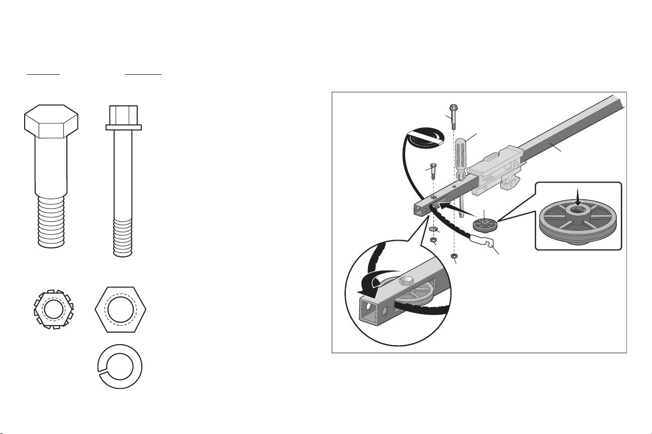
HARDWARE
H3
Bolt
H2
Bolt 1/4"-20x1-3/4"
H4
Lock Nut 1/4"-20
H6
Nut 3/8"
H7
Lock Washer 3/8"
H6
H7
H4
Screwdriver
Rail
Pulley
Trolley
Connector
H2
H3
Assembly
3 Install the pulley
3.1 Lay the beltbeside the rail, as shown.
Grasp the end with the hooked trolley
connector and passapproximately12" (30
cm)of belt through the window. Keep the
ribbed side toward the rail, and allow it to
hang.
3.2 Removethe tape fromthepulley. The
center should be greased,ifnot,regrease
the center of thepulley.
3.3 Insertthepulley into thewindow of the
frontrail.
3.4 Insertthebolt (H3) into the rail and pulley.
Tighten securely with the lockwasher (H7)
and nut(H6).
3.5 Rotate thepulley to be sure itspinsfreely.
3.6 Insertthebolt (H2) into the hole shown
and fasten with the locknut(H4).
8
Page 9
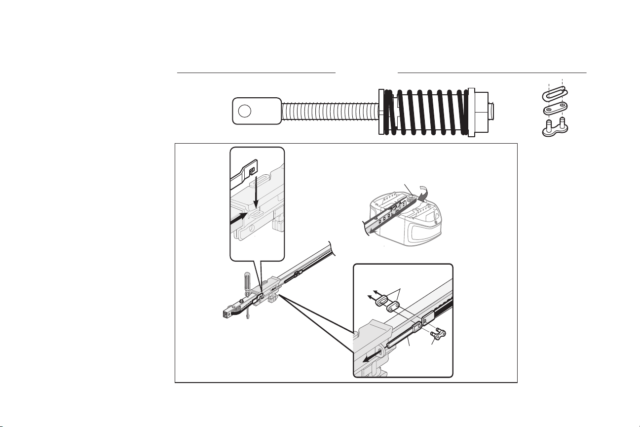
HARDWARE
H5
Master Link
H8
Spring
Trolley Nut
H1
Threaded Shaft
with
H5
H1
H5
Sprocket
Assembly
4 Install the belt
4.1 Pull thebelt around the pulleyand toward
the trolley. The ribbed side must contact
the pulley.
4.2 Hook the trolley connector into the
retaining sloton the trolley asshown.
4.3 Withthe trolley againstthescrewdriver,
dispense the remainder ofthebelt along
the rail length toward themotor unit and
around the sprocket.The sprocketteeth
mustengage thebelt.
4.4 Checktomake sure the belt is not twisted.
Connectthe trolley threaded shaft(H1)
withthe master link (H5).
• Push pinsofmaster linkbar through
holes in end ofbelt and trolley threaded
shaft(H1).
• Push master link cap over pins and past
pin notches.
• Slide clip-on spring over cap and onto
pin notches until both pins are securely
locked in place.
4.5 Removethe spring trolleynut (H8) from
the threaded shaft(H1).
4.6 Insertthetrolley threaded shaft(H1)
through the hole in the trolley.
9
Page 10
H8
Spring Trolley Nut
H9 (3)
Hex Screw #8x3/8"
(Packed with the
sprocket cover)
HARDWARE
H8
(to motor unit)
Nut ring slot
Nut Ring
BEFORE
1"
(2.5 cm)
Nut Ring
AFTER
1-1/4"
(3.18 cm)
H9
Assembly
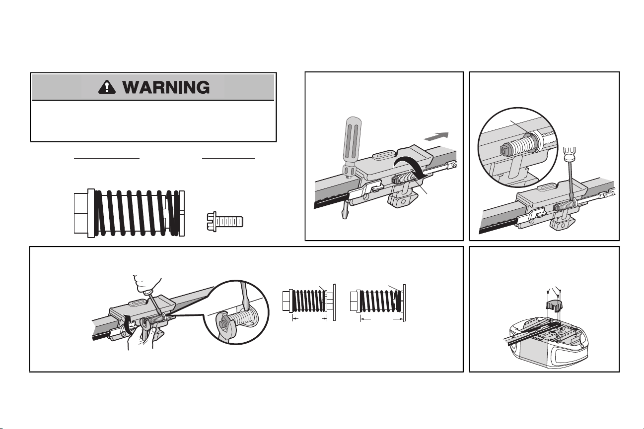
5 Tighten the belt and install the sprocket cover
5.1 By hand,thread the spring trolley nut on the
threaded shaft(H8) until it is finger tight
To avoid possible SERIOUS NJURY to finger from moving garage door opener:
• ALWAYS keep hand clear of sprocket while operating opener.
• Securely attach sprocketcoverBEFORE operating.
against the trolley. Do notuse any tools.
Removethe screwdriver.
5.3 Tighten the spring trolley nut with an adjustable wrench or a 7/16" open end wrenchabout a quarter turnuntil the spring releases and snaps the
nut ring against the trolley. This sets the spring to optimum belt tension.
10
5.2 Inserta flathead screwdriver tip intoone
of the nutring slots and brace it firmly
against the trolley.
5.4 Position the sprocket cover over thegarage
door opener sprocket and attach with hex
screws(H9).
Page 11
Installation
IMPORTANT INSTALLATION INSTRUCTIONS
To reduce the risk of SEVERE INJURY or DEATH:
1. READ AND FOLLOW ALL INSTALLATIONWARNINGS AND INSTRUCTIONS.
2. Install garage door opener ONLY on properlybalanced and lubricated garage door. An
improperly balanced door mayNOT reverse when required and could result in SEVERE
INJURY or DEATH.
3. ALL repairs to cables, spring assembliesand other hardware MUST be made bya trained
door systemstechnician BEFORE installing opener.
4. Disable ALL locksand remove ALL ropesconnectedto garage door BEFORE installing
opener to avoid entanglement.
5. Install garage door opener 7 feet(2.13 m) or more abovefloor.
6. Mount the emergencyrelease within reach, butatleast6 feet (1.83 m)above the floor and
avoiding contact with vehicles to avoid accidental release.
7. NEVER connect garage door opener to power source until instructedto do so.
8. NEVERwearwatches, rings or loose clothing while installing or servicing opener.Theycould
be caughtin garage door or opener mechanisms.
9. Install wall-mounted garage door control:
• within sight of the garage door.
• out of reachof children atminimumheight of5 feet (1.5 m).
• away from ALL moving parts of the door.
10. Placeentrapment warning label on wall nextto garage door control.
11. Placemanual release/safetyreversetestlabel in plain viewon inside of garage door.
12. Upon completion ofinstallation,testsafetyreversal system.Door MUST reverse on contact
witha 1-1/2"(3.8 cm) high object (or a 2x4 laid flat) on thefloor.
13. To avoid SERIOUS PERSONAL NJURY or DEATHfrom electrocution,disconnectALL
electricand battery power BEFORE performing any serviceor maintenance.
14. DO NOT enable the Timer-to-Close functionalityif operating either one-piece or swinging
garage doors. To be enabled ONLY when operating a sectional door.
11
Page 12
Installation
Sectional door with
curved track
Header Wall
Track
2" (5 cm)
Highest Point
of Travel
Door
One-piece door with
horizontal track
Header Wall
Track
2" (5 cm)
Highest Point
of Travel
Door
One-piece door without track:
jamb hardware
Header Wall
8" (20 cm)
Highest
Point of
Travel
Door
Jamb
Hardware
Header Wall
Unfinished
Ceiling
Vertical Centerline
of Garage Door
2x4
2x4
Structural
Supports
Level
(Optional)
OPTIONAL
CEILING
MOUNT FOR
HEADER
BRACKET
One-piece door without track:
pivot hardware
Header Wall
8" (20 cm)
Highest
Point of
Travel
Door
Pivot
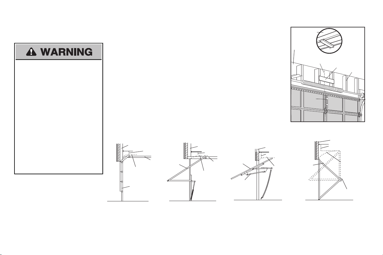
1 Determine the header bracket
location
To prevent possible SERIOUS INJURY or
DEATH:
• Header bracket MUST be RIGIDLY
fastened to structural support on header
wall or ceiling, otherwise garage door might
NOTreverse when required. DO NOT
install header bracketover drywall.
• Concreteanchors MUST be used if
mounting header bracket or 2x4 into
masonry.
• NEVER try to loosen, move or adjust
garage door, springs, cables, pulleys,
brackets, or their hardware, ALL of which
are under EXTREME tension.
• ALWAYS call a trained door systems
technician if garage door binds, sticks,or is
out of balance.An unbalanced garage
door mightNOTreverse when required.
Installation procedures vary according togarage door types.Follow the instructionswhichapply to your
door.
1.1 Close the door and markthe inside vertical centerline of the garage door.
1.2 Extend the line onto the header wall above the door.
You can fasten the header bracket within 4 feet (1.22 m) of the left orright of the door
center only if a torsionspringorcenterbearing plate is in the way; or you can attachit to
the ceiling when clearance is minimal.(Itmay be mounted on the wallupside down if
necessary, to gain approximately 1/2" (1 cm).
Ifyou need to install the header bracketon a 2x4 (on wall or ceiling), use lag screws(not
provided) tosecurelyfasten the2x4 to structural supports.
1.3 Open your door to the highestpoint of travel as shown.Drawan intersecting horizontal line on
the header wall 2"(5 cm) abovethe high point.
• 2" (5 cm)above the high pointfor sectional door and one-piece door with track.
• 8" (20 cm) above the high point for one-piece door withouttrack. Thisheight will provide travel
clearance for thetop edge of the door.NOTE:If the total number of inches exceeds the height
available in your garage, use the maximumheight possible, or refer to page 13 for ceiling
installation.
12
Page 13
HARDWARE
H11 (2)
Lag Screw
5/16"-9x1-5/8"
UP
Wall Mount
Optional
Mounting
Holes
H11
Vertical
Centerline of
Garage Door
(Header Wall)
Header
Bracket
2x4 Structural
Support
Door Spring
(Garage Door)
Highest Point of
Garage Door
Travel
Horizontal
Line
UP
(Header Wall)
Ceiling Mounting Holes
(Finished Ceiling)
Vertical
Centerline of
Garage Door
Header
Bracket
6" (15 cm)
Maximum
Door Spring
(Garage Door)
H11
Installation
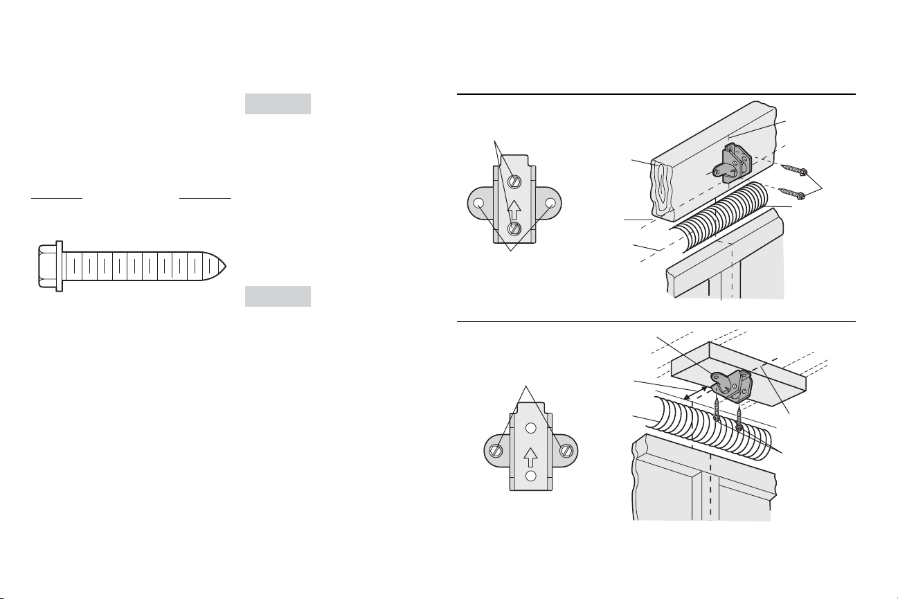
2 Install the Header Bracket
You can attachthe headerbracketeither to the
wall above thegarage door, or to the ceiling.
Follow the instructionswhich will work bestfor
your particular requirements.Donot install the
header bracket over drywall.If installing into
masonry,use concrete anchors (not provided).
OPTION A WALL INSTALLATION
2.1A Center the bracket on the vertical
centerline with the bottom edge of the
bracketon the horizontal line as shown
(with the arrowpointing toward the
ceiling).
2.2A Markthe vertical set of bracket holes (do
not use the holes designated forceiling
mount).Drill 3/16" pilotholes and fasten
the bracket securely to a structural
support with the hardware provided
(H11).
OPTION B CEILING INSTALLATION
2.1B Extend the vertical centerline onto the
ceiling asshown.
2.2B Center the bracket on the verticalmark,
no more than 6" (15 cm) from the wall.
Make sure the arrow is pointing away
fromthe wall. The bracketcanbe
mounted flush againstthe ceiling when
clearance is minimal.
2.3B Markthe side holes.Drill 3/16" pilotholes
and fasten bracket securely to a structural
support with the hardware
provided (H11).
13
Page 14
H12
H19
HARDWARE
H12
Clevis Pin 5/16"x1-1/2"
H19
Ring Fastener
Connected Disconnected
One-piece
door
without
tracks
All other
door types
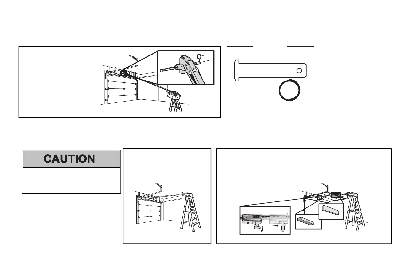
Installation
3 Attach the rail to the header bracket
3.1 Align the rail withthe header
bracket.Insert the clevis pin
(H12) through the holesin the
header bracketand rail.Secure
withthe ring fastener (H19).
NOTE: Use the packing material as a
protective base for the garage door
opener.
4 Position the garage door opener
To prevent damage to garage door, restgarage
door opener rail on 2x4 placed on top section of
door.
4.1 Removethe packing material and liftthe
garage door opener onto a ladder.
NOTE: A 2x4 is ideal for setting the distance
between the rail and the door. Ifthe ladder is
not tall enough you will need help at this point.
14
4.2 Fullyopen the door and placea 2x4 (laid flat) under the rail.For one-piecedoors without
tracks,lay the 2x4 on it's side.
NOTE: Ifthe door hitsthe trolley when itis raised, pull the trolley release arm down to
disconnectthe inner and outer trolley. Slide the outer trolley toward the garage door opener.
The trolley can remain disconnected until instructed.
Page 15
HARDWARE
H10 (2)
Lag Screw 5/16"- 18x1-7/8"
H15 (2)
Hex Bolt 5/16"- 18x7/8"
H21 (2)
Nut 5/16"-18
H20 (2)
Lock Washer
5/16"-18
Finished Ceiling
Unfinished Ceiling
Finished
Ceiling
H10
(not provided)
H10
(not provided)
H15
H20
H21
Installation
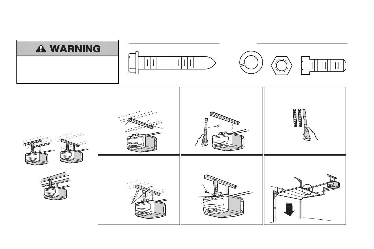
5 Hang the garage door opener
To avoid possible SERIOUS NJURY from a
falling garage door opener,fasten it SECURELY to
structural supportsofthegarage. Concrete anchorsMUST
be usedif installing ANY bracketsintomasonry.
Hanging thegarage door opener will vary
depending on your garage.Below are three
example installations.Your installation maybe
different.ForALL installations the garage door
opener MUSTbe connected to structural
supports.Theinstructions illustrate one of the
examples below.
5.1 On finished ceilings,use the lag screws
(H10) to attach a support bracket (not
provided) tothe structural supports
before installing the garage door opener.
5.4 Attach the end ofeach hanging bracketto
the support bracket with appropriate
hardware (not provided).
5.2 Makesure the garage door opener is
aligned withthe header bracket.Measure
the distance from each side of the garage
door opener tothe support bracket.
5.5 Attach the garage door opener to the
hanging bracketswith the bolts(H21),
lockwashers(H15) and nuts (H20).
15
5.3 Cutboth pieces of the hanging bracket
(not provided) to required lengths.
5.6 Removethe 2x4 and manually close the
door. If the door hits the rail,raise the
header bracket.
Page 16

or
or
NOT CE
Installation
6 Install the light bulbs
To prevent possible OVERHEATNG of the end panel or light socket:
• UseONLY A19 incandescent or compact fluorescent light bulbs.
• DO NOT use incandescentbulbs larger than 100W.
• DO NOT use compact fluorescentlight bulbslarger than 26W (100W) equivalent.
• DO NOT use halogen bulbs.
• DO NOT use shortneckor specialtylight bulbs.
7 Attach the emergency release rope and handle
To prevent possible SERIOUS INJURY or DEATH from a falling garage door:
• Ifpossible,use emergency releasehandle todisengage trolley ONLY when garage door is
CLOSED. Weak or broken springs or unbalanced door could result in an open door falling
rapidly and/or unexpectedly.
• NEVER use emergencyrelease handle unless garage doorwayisclear of personsand
obstructions.
• NEVER use handle to pull door open or closed. If rope knotbecomesuntied, you could fall.
6.1 Pull on the topsides of the lightlens and
rotate the lightlens down.
6.2 Insertan A19 incandescent or compact
fluorescentlight bulb (100 watt maximum),
into the lightsocket.
6.3 Rotatethe lens up to close.
NOTE: The use ofshort neck or speciality light
bulbs may overheatthe end panel or light socket.
7.1 Insertone end of the emergencyrelease
rope through the handle. Make sure that
“NOTICE” isright side up.Tiea knot at
least1 inch(2.5 cm) from the end of the
emergency release rope.
7.2 Insertthe other end of the emergency
release rope through the hole in the
trolley release arm.Makesure the
handle is 6 feet (1.83m) above the floor
and secure with a knot.
NOTE: Ifit is necessaryto cut the emergency
release rope, seal the cutend with a match or
lighter to prevent unraveling. Ensure the
emergency release rope and handle are
above the top of all vehicles to avoid
entanglement.
16
Page 17

H16 (2)
Self-Threading Screw
1/4˝-14x5/8˝
HARDWARE
A horizontal and vertical reinforcement
is needed for lightweight garage doors
(fi berglass, aluminum, steel, doors
with glass panel, etc.) (not provided).
A horizontal reinforcement brace
should be long enough to be secured
to two or three vertical supports.
A vertical reinforcement brace should
cover the height of the top panel.
FIGURE 1
FIGURE 2
FIGURE 4
FIGURE 5
FIGURE 3
Vertical Reinforcement
Vertical Centerline
of Garage Door
UP
Door Bracket
H16
Vertical Reinforcement
Vertical Centerline
of Garage Door
Bolt 5/16"-18x2"
(not provided)
Lock Washer 5/16"
Nut 5/16"-18
Door Bracket
UP
Vertical Centerline
of Garage Door
UP
H16
Vertical
Centerline of
Garage Door
Bolt 5/16"-18x2"
(not provided)
UP
Inside Edge of Door or
Reinforcement Board
Installation
8 Install the door bracket
Fiberglass,aluminum or lightweight steel garage doors WILLREQUIREreinforcementBEFORE
installation of door bracket.Contact your door manufacturer for reinforcement kit.
Figure 1 showsone pieceof angle iron asthe horizontal brace.
For the vertical brace,2 pieces of angle iron are used to create a
U-shaped support. The bestsolution is to check with your garage
door manufacturer for an opener installation door reinforcement
kit.
NOTE: Many door reinforcement kitsprovide for directattachment
of the clevis pin and door arm. In this case you will not need the
door bracket; proceed to the next step.
OPTION A SECTIONALDOORS
8.1A Center the door bracketon the previouslymarkedvertical centerline used forthe header bracket
installation.NotecorrectUP placement,as stamped inside thebracket.
8.2A Position the top edge of the bracket 2"-4" (5-10 cm) belowthe top edge of the door, OR directly
below anystructural support across the top of the door.
8.3A Mark,drill holesand install asfollows,depending on your door’s construction:
Metal or light weight doors usinga vertical angle iron brace between the door panelsupport
and the doorbracket:
• Drill 3/16" fastening holes.Secure the door bracket using thetwoselfthreading screws (H16).
(Figure 2)
• Alternately,use two 5/16" bolts,lockwashersand nuts(not provided). (Figure 3)
Metal,insulated or light weight factory reinforced doors:
• Drill 3/16" fastening holes.Secure the door bracket using theself-threading screws(H16).
(Figure 4)
Wood Doors:
• Usetop and bottomor side toside door bracketholes. Drill 5/16” holes through the door and
secure bracket with 5/16"x2" carriage bolts,lockwashers and nuts (not provided).(Figure 5)
NOTE: The 1/4"-14x5/8" self-threading screws are not intended for use on wood doors.
17
Page 18

For a door with no exposed framing, or for the
optional installation, use lag screws 5/16"x1-1/2"
(not provided) to fasten the door bracket.
Vertical
Centerline
of Garage
Door
Optional
Placement
of Door
Bracket
Door Bracket
Header Bracket
Header Wall
2x4 Support
(Finished Ceiling)
H16
Door
Bracket
Top of Door
(Inside Garage)
Top Edge of
Door
Optional
Placement
Optional
Placement
Top Edge
of Door
Top of Door
(Inside Garage)
Door
Bracket
Carriage Bolt 5/16"x2"
(not provided)
Nut 5/16"-18
Lock Washer 5/16"
Metal Door
Wood Door
Installation
8 Install the door bracket
OPTION B ONE-PIECEDOORS
8.1B Center the door bracketon the top of the
door, in line with the header bracketas
shown.
8.2B Mark either theleftand right,or the top
and bottom holes.
Metal Doors:
• Drill 3/16"pilot holesand fasten the bracket
withthe self-threading screws (H16)
provided.
Wood Doors:
• Drill 5/16"holes and use 5/16"x2" carriage
bolts,lockwashers and nuts (not provided)
or 5/16"x1-1/2" lag screws(notprovided)
depending on your installation needs.
NOTE: The door bracket may be installed on the
top edge of the door if required for your
installation.(Refer to the dotted line optional
placement drawing.)
18
Page 19

H20
H21
H15
H13
H19
H19
H14
H20
H13
H19
H15
H21
H14
H19
One-Piece Door without Track
One-Piece Door with Track
Straight
Door Arm
Curved
Door
Arm
(Groove
facing out)
CORRECT
FIGURE 1
INCORRECT
Straight
Door
Arm
Curved
Door
Arm
HARDWARE
H15
Hex Bolt 5/16"-18x7/8"
H20
Nut
5/16"-18
H21
Lock
Washer
5/16" -18
H14
Clevis Pin 5/16"x1"
H13
Clevis Pin 5/16"x1-1/4"
H19
Ring Fastener
Installation
9 Connect the door arm to the trolley
Installation willvaryaccording to thegarage door type. Follow the instructions which applytoyour door.
IMPORTANT: The groove on the straight door arm MUST face away from the curved door arm (Figure 1).
OPTION A ONE-PIECE DOORS
9.1A Close the door.Disconnect the trolley
by pulling the emergencyrelease
handle.
9.2A Fastenthe straight door arm and the
curved door arm together tothe
longest possible length (with a 2 or 3
hole overlap) using the bolts (H15),
nuts(H20) and lock washers (H21).
9.3A Attachthe straight door arm to the door
bracketusing the clevis pin (H13).
Secure with the ring fastener (H19).
9.4A Attachthe curved door arm to the
trolley using the clevispin (H14).
Secure with the ring fastener (H19).
9.5A Pull the emergency releasehandle
toward the garage door opener until
the trolley releasearm is horizontal.
19
Page 20

H14
H13
H19
H19
H15
H20
H21
Straight
Door Arm
Curved
Door
Arm
(Groove
facing out)
CORRECT INCORRECT
FIGURE 1
Straight
Door
Arm
Curved
Door
Arm
HARDWARE
H15
Hex Bolt 5/16"-18x7/8"
H20
Nut
5/16"-18
H21
Lock
Washer
5/16" -18
H14
Clevis Pin 5/16"x1"
H13
Clevis Pin 5/16"x1-1/4"
H19
Ring Fastener
Installation
9 Connect the door arm to the trolley
OPTION B SECTIONAL DOORS
IMPORTANT: The groove on the straight door arm
MUSTface awayfrom the curved door arm (Figure 1).
9.1B Close the door.Disconnect the trolley by
pulling the emergency releasehandle.
9.2B Attachthe straight door arm to the outer
trolley using the clevispin (H14). Secure with
the ring fastener (H19).
9.3B Attachthe curved door arm to thedoor
bracketusing the clevis pin (H13). Secure
withthe ring fastener (H19).
9.4B Bring arm sectionstogether.Find two pairsof
9.5B Pull the emergency releasehandle toward
NOTE: Ifthe holes in the curved door arm and the
straight door arm do notalign, reverse the straight
door arm,selecttwo holes(as far apartas possible)
and attach using bolts (H15), nuts (H20), and lock
washers (H21). If the straight door arm is hanging
down too far,you may cut 6 inches (15 cm) from the
solid end.
holes that line up and join sections. Select
holes as farapart as possible toincrease
door arm rigidity and attachusing the bolts
(H15), nuts (H20) and lock washers (H21).
the garage door opener until the trolley
release armis horizontal. The trolley will reengage automaticallywhen the garage door
opener is activated.
20
Page 21

Install the Door Control
HARDWARE
Screw
6ABx1-1/2" (2)
Drywall
Anchors (2)
Screw
6-32x1" (2)
7/16"
(11 mm)
Wall
DRYWALL
GANG BOX
6ABx1-1-1/2"
6-32x1"
Drywall Anchor
1 Install the door control
INTRODUCTION
Compatible with MyQ™ enabled accessories,
To prevent possible SERIOUS INJURY or DEATH from electrocution:
• Be sure power is NOTconnectedBEFORE installing door control.
• ConnectONLY to 12 VOLTlow voltage wires.
To prevent possible SERIOUS INJURY or DEATH from a closinggarage door:
• Install door control within sightofgarage door, out ofreach of children at a minimumheight of 5 feet
(1 5 m),and awayfromALL moving partsof door.
• NEVER permit children to operateor playwith door control pushbuttonsor remote control
transmitters.
• Activate door ONLY when it can be seen clearly,is properly adjusted,and there are no
obstructions to door travel.
• ALWAYS keep garage door in sight untilcompletelyclosed. NEVER permitanyone to crosspathof
closing garage door.
NOTE: For gang box installations it is not necessaryto drill holesor install the drywall anchors. Use the existing holes in the gang box.
1.1 Strip 7/16 inch (11 mm)of insulation from
one end of the wire and separate the wires.
1.2 Connectone wire to each ofthe two screws
on the backof the door control.The wires
can be connected to either screw.
PRE-WIREDINSTALLATIONS:Choose
any two wires to connect, note which wires
are used so the correct wires are connected
to the garage door opener in a later step.
see page 47. Your garage door opener is
compatible with up to2 MyQ™ door controls.
NOTE: Older Chamberlain door controls and
third party products are not compatible.
Install thedoor controlwithin sight of the door at
a minimum heightof 5 feet(1.5m) where small
children cannotreach, and awayfromthe
moving parts of the door.
NOTE: Your product may look different than the
illustrations.
1.3 Mark the location ofthe bottom mounting
hole and drill a 5/32 inch (4 mm)hole.
1.4 Install the bottom screw,allowing 1/8 inch
(3 mm) to protrude from the wall.
21
Page 22

Install the Door Control
DRYWALL
6ABx1-1/2"
Drywall Anchor
6-32x1"
GANG BOX
HARDWARE
Insulated Staple
Staple
7/16"
(11 mm)
RED
WHITE
WHITE
GREY
1.5 Position the bottom hole of the door
control over the screwand slide
down into place.
1.6 Liftthe push bar up and mark the top hole. 1.7 Removethe door control from the wall
2 Wire the door control to the garage door opener
2.1
Run the white and red/white wire fromthe door control to
the garage door opener. Attachthe wire to thewall and
ceiling with the staple (not applicable for gang box or prewired installations). Do not pierce the wire withthe staple
as this may cause a shortor an open circuit.
PRE-WIRED INSTALLATIONS: When wiring
the door control to the garage door opener
make sure you use the same wires thatare
connected to the door control.
and drill a 5/32 inch (4 mm) hole for
the top screw.
2.2
Strip 7/16 inch (11 mm)of insulation
fromthe end of the wire near the
garage door opener.
22
door controlover the screw and
slide down into place. Attach the
top screw.
2.3
Connectthe wire to the red and
white terminals on thegarage
door opener. To insertor
release wires fromthe terminal,
push in the tab with screwdriver
tip.
1.8 Position the bottom hole of the
Page 23

Install the Door Control
Safety Reversing Sensor
6" (15 cm) max. above floor
Invisible Light
Beam Protection
Area
3 Attach the warning labels
3.1 Attach theentrapment warning label on the wall near thedoor controlwithtacks or staples.
3.2 Attach themanual release/safetyreverse testlabel in a visible locationon the inside of the garage
door.
Install the Protector System
Introduction
Be sure power is NOTconnectedto the garage
door opener BEFORE installing the safety
reversing sensor.
To prevent SERIOUS INJURY or DEATHfrom
closing garage door:
• Correctlyconnectand align the safetyreversing
sensor.Thisrequired safety device MUST NOT
be disabled.
• Install thesafety reversing sensorso beam is
NO HIGHERthan 6" (15 cm) abovegarage
floor.
®
IMPORTANTINFORMATIONABOUTTHESAFETYREVERSINGSENSORS
The safety reversing sensors must be connected andalignedcorrectly beforethe garage door
openerwill move in the down direction.
The sending sensor (with an amber LED)transmits an invisible light beam to the receiving sensor (with a
green LED).Ifan obstruction breaks the light beam while the door is closing, the door will stop and reverse
to the full open position, and the garage door opener lights will flash 10 times.
NOTE: For energyefficiency the garage door opener will enter sleep mode when the door is fully closed.
The sleep mode shuts the garage door opener down until activated. The sleep mode is sequenced with the
garage door opener light bulb; as the light bulb turns off the sensor LEDswill turn off and whenever the
garage door opener lightsturn on the sensor LEDs will light.The garage door opener will not go into the
sleep mode until the garage door opener has completed 5 cycles upon power up.
Wheninstalling the safety reversingsensors check the following:
• Sensorsare installed inside the garage, one on either side of the door.
• Sensorsare facing eachother with the lensesaligned and thereceiving sensor lensdoes not receive
direct sunlight.
• Sensorsare no more than 6 inches (15 cm) above thefloor and the lightbeam is unobstructed.
23
Page 24

Install the Protector System
HARDWARE
H17 (2)
Carriage Bolt
1/4"-20x1/2"
H18 (2)
Wing Nut
1/4"-20
no more
than
6 inches
(15 cm)
H17
H18
(not provided)
no more
than
6 inches
(15 cm)
In
side
G
a
rage
Wa
l
(not provided)
H17
Lens
H18
®
1 Install the Safety Reversing Sensors
The safetyreversing sensors can be attached to the door track,the wall,or the floor.The sensors should be no more than 6 inches (15 cm) above the floor.Ifthe door trackwill not support the sensor
bracketa wall installation isrecommended. Choose one of the following installations.
OPTION A
1.1A Slide the curved armsofthe sensor
OPTION B WALLINSTALLATION
Ifadditional clearanceis needed an extension bracket(notprovided) or wood blockscanbe used. Make sure each bracket has the sameamount of clearance so they will align correctly.
1.1B Position the sensor bracketagainstthe
wall with the curved armsfacing the
door. Make sure there is enough
clearance for thebeam to be
unobstructed.Markholes.
1.2B Drill 3/16 inch pilot holesfor each
DOOR TRACK INSTALLATION
bracketaround the edge of the door
track. Snap into placeso thatthe
sensor bracket is flush againstthe
track.
sensor bracket and attach the sensor
bracketsto thewall using lag screws
(not provided).
1.2A Slide the carriage bolt (H17)
into the slot on each sensor.
1.3B Slide the carriage bolt (H17) into
the slot on each sensor.
1.3A Insertthebolt through the hole in the sensor
bracketand attach with the wing nut (H18). The
lenses on both sensors should point toward
each other. Make sure the lens isnot obstructed
by the sensor bracket.
1.4B
Insertthebolt through the hole in the sensor
bracketand attach with the wing nut (H18). The
lenses on both sensors should point toward
each other. Make sure the lens isnot
obstructed bythe sensor bracket.
24
Page 25

Install the Protector System
nsi
d
e
G
arage
Wa
l
(not provided)
H17
H18
HARDWARE
Insulated Staple
Staple
7/16"
(11 mm)
RED
WHTE
WHTE
GREY
1 Install the Safety Reversing Sensors
®
OPTION C
FLOOR INSTALLATION
Usean extension bracket(not provided) or wood black to raise the sensor bracket if needed.
1.1C Carefullymeasure the position ofboth
sensor bracketsso they will be the same
distancefromthe wall and unobstructed.
1.2C
Attach thesensor bracketstothe floor
using concrete anchors (not
provided).
2 Wire the Safety Reversing
Sensors
PRE-WIRED INSTALLATIONS: If your garage
already haswiresinstalled for the safety
reversing sensors,proceed topage 26.
OPTION A
2.1A Run the wire from both sensors to the
INSTALLATION WITHOUT PRE-WIRING
garage door opener. Attach the wire to
the wall and ceiling withthe staples.
1.3C
Slide the carriage bolt (H17)
into the slot on each sensor.
2.2A Strip 7/16 inch (11 mm)of
insulation from eachsetof
wires.Separate the wires.Twist
the white wires together. Twist
the white/blackwirestogether.
25
1.4C
Insertthebolt through the hole in the sensor
bracketand attach with the wing nut (H18). The
lenses on both sensors should point toward
each other. Make sure the lens isnot obstructed
by the sensor bracket.
2.3A Insertthewhite wires into the whiteterminal on
the garage door opener. Insert the white/black
wires into the grey terminal on the garage door
opener. To insertor remove thewires from the
terminal,push in the tab with a screwdrivertip.
Page 26

Install the Protector System
7/16"
(11 mm)
7/16"
(11 mm)
Safety reversing sensor wires
Pre-installed
wires
White
White/Black
Yellow
(for example)
Purple
(for example)
Not Provided
Pre-installed
wires
Safety reversing sensor wires
7/16"
(11 mm)
Yellow
Purple
RED
WH TE
WH TE
DREDRE
GREY
Purple
(for
example)
Yellow
(for example)
To insert or remove
the wires from the
terminal, push in the
tab with a screwdriver tip.
OPTION B PRE-WIRED INSTALLATION
®
2.1B Cutthe end of the safety
reversing sensor wire, making
sure there isenough wire to
reach the pre-installed wires
2.2B Separate thesafetyreversing sensorwires and strip 7/16 inch (11 mm) of
insulation from eachend. Choose two of thepre-installed wires and strip 7/16
inch (11 mm) of insulation fromeach end. Make sure that you choose the
same color pre-installed wires for eachsensor.
fromthe wall.
2.4B At the garage door opener, strip 7/16inch (11 mm)of insulation fromeach end of the wires previouslychosen for the
safety reversing sensors. Twistthe like-colored wires together.
26
2.3B Connectthe pre-installed wires to the sensor wires with wire nuts
making sure the colors correspond foreach sensor. For example,
the white wire would connect to the yellowwire and the white/black
wire would connecttothe purple wire.
2.5B Insertthewires connected to the whitesafety sensor wires to the
white terminal on the garage door opener. Insert the wiresthatare
connected to the white/black safetysensor wiresto the grey
terminal on the garage door opener.
Page 27

Ground Tab
Green Ground
Screw
Ground Wire
Black
Wire
White Wire
PERMANENT WIRING
Wire Nuts
TYPICAL WIRING
Power
1 Connect Power
To prevent possible SERIOUS INJURY or
DEATHfromelectrocution or fire:
• Be sure power is NOTconnectedto the
opener, and disconnect power to circuit
BEFORE removing coverto establish
permanent wiring connection.
• Garage door installation and wiring MUST
be in compliance with ALL local electrical
and building codes.
• NEVER use an extension cord, 2-wire
adapter, or change plug in any way to make
it fitoutlet.Be sure the opener is grounded.
To avoidinstallation difficulties, do not activate the garage door openerat this time.
To reduce the risk of electric shock,yourgarage door opener has a grounding type plug with a third
grounding pin. This plug will onlyfitintoa grounding type outlet. Ifthe plug doesn’t fit into your outlet,
contacta qualified electrician to install the proper outlet.
THERE ARE TWO OPTIONS FOR CONNECTINGPOWER:
OPTION A
TYPICAL WIRING
1.1A Plug in the garage door opener into a grounded outlet.
1.2A DO NOT run garage door opener atthistime.
OPTION B
If permanent wiring is required by your localcode, refer to the followingprocedure. To make a
permanent connection throughthe 7/8 inch hole in the topof the motor unit (accordingtolocal
code):
PERMANENT WIRING
1.1B Be sure power is NOTconnectedto the opener,and disconnect power to circuit.
1.2B Removethe garage door opener coverand setaside.
1.3B Removethe attached green ground terminal.
1.4B Cutblackand whitewiresand strip away1/2inch (1 cm)ofinsulation, 3 inch(7 5 cm) before
spade terminals.
1.5B Removethe power cord from opener.
1.6B Install a conduit or flexcable adapterto the 7/8 inch hole.
1.7B Run wires through conduit, cutto proper length and strip insulation.
1.8B Attach with wire nutsprovided. Attach the ground wire tothe green ground screw.The opener
must be grounded.
1.9B Properly secure wire under plastictiesso that wire doesnot come in contact with moving parts.
1.10B Reinstall the cover. DO NOT run garage door opener at thistime.
27
Page 28

Green LED
ROSNES GNIVIECERROSNES GNIDNES
Amber LED
If the receiving sensor is in
direct sunlight, switch it with
sending sensor so it is on the
opposite side of the door.
(invisible light beam)
Make sure there is
power to the garage
door opener.
Make sure the
sensor wire is not
shorted/broken.
RED
WHITE
WHITE
GREY
Make sure the sensor has been wired
correctly: white wires to white terminal
and white/black wires to grey terminal.
Make sure the sensors are aligned.Make sure the sensor wire is
not shorted/broken.
Power
2 Ensure the Safety Reversing Sensors are aligned
The door willnot close if the sensors have not been
installedandaligned correctly.
When the light beam isobstructed or misaligned while
the door is closing, the door will reverse and the
garage door opener lightswill flash ten times.Ifthe
door isalready open,it will notclose. The sensorscan
be aligned by loosening the wing nuts,aligning the
sensors,and tightening the wing nuts.
.
IFTHE AMBER LED ON THE SENDING SENSOR IS NOT GLOWING: IFTHE GREEN LED ON THE RECEIVING SENSOR IS NOT GLOWING:
2.1 Checkto make sure the LEDsin bothsensorsare glowing steadily.TheLEDs in both sensorswill glow steadily if theyare aligned and
wired correctly.
3 Ensure the Door Control is wired correctly
Ifthe door control has been installed and wired correctly,a message will displayon the SmartControl Panel screen or thecommand LED on the Motion-DetectingControl Panel will blink.
28
Page 29

UP (Open)
DOWN (Close)
CORRECT
INCORRECT
UP Button
Adjustment
Button
DOWN Button
PROGRAMMING BUTTONS
Adjustments
Withouta properly installed safetyreversal
system,persons(particularly small children)
could be SERIOUSLY INJURED or K LLEDby a
closing garage door.
• Incorrectadjustment of garage door travel
limitswillinterfere with proper operation of
safety reversal system.
• AfterANY adjustmentsare made, thesafety
reversal system MUST be tested. Door
MUSTreverse on contact with 1-1/2" (3.8
cm)high object(or 2x4 laid flat) on floor.
To prevent damage to vehicles,be sure fully
open door providesadequate clearance.
To watcha short instructional video on how to
program thetravel on your new garage door
opener use your smartphone to read the QR Code
below:
INTRODUCTION
Your garage door opener is designed with
electronic controlsto make setup and
adjustmentseasy. The adjustmentsallow you to
program where the door will stop in the open
(UP) and close (DOWN) position. The
electronic controlssense the amountofforce
required to open and closethe door. The force
is adjusted automaticallywhen you program
the travel.
NOTE: Ifanything interferes with the door’s
upward travel it will stop. Ifanything interferes
with the door’sdownward travel, it will reverse.
ONE-PIECE DOORS ONLY
When setting the UP travel for a one-piece
door ensure that the door does not slant
backwardswhen fully open (UP). Ifthe door is
slanted backwardsthiswill cause unnecessary
bucking and/or jerking when the door is
opening or closing.
PROGRAMMING BUTTONS
The programmingbuttonsare located on the
leftside panel of the garage door opener and
are used to programthe travel.
29
Page 30

Adjustments
1 Program the
Travel
Withouta properly installed safetyreversal system,persons (particularly small children) could be SERIOUSLY INJURED or K LLEDby a closing garage door.
• Incorrectadjustmentofgarage door travel limitswill interfere with proper operation of safetyreversal system.
• After ANY adjustments are made, the safetyreversal system MUSTbe tested. Door MUST reverse on contactwith 1-1/2"(3.8 cm) high object (or 2x4 laid flat) on
floor.
1.1 Press and hold the
AdjustmentButtonuntil
the UP Button begins to
flash and/or a beep is
heard.
1.5 Once the door isin the
desired DOWN position
press and release the
AdjustmentButton.The
garage door opener
lights will flash twice
and theUP Button will
begin toflash.
1.2 Press and hold theUP Button until thedoor isin
the desired UP position.
NOTE: The UPand DOWNButtons can be
used to move the door up and down asneeded.
1.6 Press and release the UP Button.When the
door travelsto theprogrammed UPposition,the
DOWNButton will begin to flash.
1.3 Once the door isin the desired UP position
press and release the Adjustment Button. The
garage door opener lightswill flash twiceand
the DOWN Button will begin to flash.
1.7 Press and release the DOWNButton.Thedoor
will travel to the programmed DOWN position.
Programming iscomplete.
30
1.4 Press and hold theDOWNButton until the door
is in thedesired DOWNposition.
NOTE: The UPand DOWNButtons can be
used to move the door up and down asneeded.
*
Ifthe garage door opener lightsare flashing 5
timesduring thestepsforProgram theTravel,the
programming has timed out. Ifthe garage door
opener lights are flashing 10 times during the steps
for Programthe Travel, the safetyreversing
sensorsare misaligned or obstructed (refer to
page 28). When thesensorsare aligned and
unobstructed,cycle the door through a complete
up and down cycle using the remote control or the
UP and DOWNbuttons.Programming is complete.
Ifyou are unable tooperate the door up and down,
repeat the steps for Programming the Travel.
Page 31

Adjustments
2 Test the Safety Reversal System
Withouta properly installed safetyreversal system,
persons (particularly small children) could be
SERIOUSLY INJURED or K LLEDbya closing
garage door.
• Safetyreversal system MUSTbe tested every
month.
• AfterANY adjustmentsare made, thesafety
reversal system MUST be tested. Door MUST
reverse on contact with 1-1/2" (3.8cm)high
object (or 2x4 laid flat)on the floor.
3 Test the Protector System
Without a properly installed safety reversing
sensor, persons (particularly small children) could
be SERIOUSLY INJUREDor KILLED bya closing
garage door.
®
2.1 With the door fully open, placea 1-1/2
inch (3.8 cm) board (or a 2x4 laid flat) on
the floor, centered under the garage
door.
3.1 Open the door. Place the garage door
opener carton in thepath of the door.
2.2 Press the remote control push button to
close the door.The door MUSTreverse
when it makes contactwiththe board.
3.2 Press the remote control push button to
close the door.The door will not move
more than an inch (2 5 cm),and the
garage door opener lightswill flash 10
times.
Ifthe door stops and does notreverseon
the obstruction,the travel needs tobe
adjusted (refer toAdjustmentStep 1).
Repeat the test.When the door reverses
upon contact with the 1-1/2inch board,
remove the board and open/close the
door 3 or 4 times to testthe adjustment.
Ifthe testcontinues to fail,call a trained
door systemstechnician.
The garage door opener will not close
froma remote control ifthe LED in either
safety reversing sensoris off(alerting you
to the fact thatthe sensor is misaligned or
obstructed).
Ifthe garage door opener closesthe door
when the safety reversing sensor is
obstructed (and the sensorsare no more
than 6 inches [15 cm]above the floor),call
for a trained door systemstechnician.
31
Page 32

Battery
Status LED
Battery Backup
To reduce the risk of FIREor INJURY topersons:
• Disconnect ALL electricand battery power
BEFORE performing ANY service or
maintenance.
• UseONLY Chamberlain part # 41A6357-1
for replacement battery.
• DO NOT dispose ofbatteryin fire. Battery may
explode. Check with local codes fordisposal
instructions.
1 Install the battery
1.1 Unplug thegarage door opener.
1.2 Open the light lenson the right side panel of the garage door opener. Use a Phillips
head screwdriver to removethe battery cover on the garage door opener.
1.3 Partially insert the batteryintothe battery compartmentwith theterminalsfacing out.
1.4 Connectred (+) and black(-) wires fromthegarage door opener tothe
corresponding terminalson the battery.
1.5 Replace the battery cover.
1.6 Plug in the garage door opener.
1.7 Wait for the green Battery StatusLED to start flashing before proceeding totestthe
battery.
2 Test the battery
ALWAYS wear protectivegloves and eye
protection when changing the batteryor working
around the battery compartment.
2.1
Unplug the garage door
opener. The batterystatus LED
will either glow solid orange
indicating opener is operating
on battery power or will flash
indicating low batterypower.
NOTE: Make sure the garage
door opener is unplugged.
2.2
Open and close thedoor using the
remote control or door control.
NOTE: The garage door opener may
run slower if the battery is not fully
charged. The battery will take 24 hours
to fully charge.
32
2.3 Plug in the garage door opener.Verify
the battery status LEDflashing green,
indicating the battery is charging.
Page 33

Battery Status LED
Battery Backup
Charge the Battery
The battery charges when the garage door opener
is plugged into a 110Vac electrical outletthat has
power and requires24 hourstofullycharge. A fully
charged battery supplies12Vdc to the garage door
opener for one to two days of normal operation
during an electrical power outage. After the
electricalpower hasbeen restored, the batterywill
recharge within 24 hours.The batterywill last
approximately 1 to 2 years with normalusage.
Instructionsfor replacement are provided with the
battery.To obtain maximum batterylife and prevent
damage, disconnect the battery when the garage
door opener isunplugged for an extended period
of time,suchas a summer or winter home.
NOTE: When the garage door opener is in battery
backup mode the garage door opener lights,
Timer-to-Close, and Remote Close features are
unavailable.
Battery status LED
GREEN LED:
All systemsare normal.
• A solid green LED light indicatesthe batteryis
fullycharged.
• A flashing green LED indicates the battery is
being charged.
ORANGE LED:
The garage door opener has lost power and is in
batterybackup mode.
• A solid orange LED with beep,sounding
approximately every 2 seconds, indicates the
garage door opener isoperating on battery
power.
• A flashing orange LED with beep, sounding
every 30 seconds, indicates the battery is low.
RED LED:
The garage door opener's12V battery needstobe
replaced.
• A solid red LEDwithbeep, sounding every 30
seconds,indicatesthe12V battery will no
longer hold a charge and needsto be
replaced. Replace the batterybackup to
maintain the battery backup feature.
NOTE: The Battery Status LED is most visible with
the garage door opener light off. Batterydoes not
have to be fully charged to operate the garage
door opener.
33
Page 34

Operation
IMPORTANT SAFETYINSTRUCTIONS
To reduce the risk of SEVERE INJURY or DEATH:
1. READ AND FOLLOW ALL WARNINGS AND NSTRUCTIONS.
2. ALWAYS keep remote controls out ofreach of children.NEVER permit children to operateor
play with garage door control push buttons or remote controls.
3. ONLY activate garage door when it can be seen clearly,itisproperly adjusted,and there are
no obstructionsto door travel.
4. ALWAYS keep garage door in sight and away from people and objectsuntil completely
closed. NO ONE SHOULDCROSS THE PATH OF THE MOVING DOOR.
5. NO ONE SHOULDGO UNDER A STOPPED,PARTIALLY OPENED DOOR.
6. Ifpossible,use emergency releasehandle todisengage trolley ONLY when garage door is
CLOSED. Use caution when using the release with the door opener.Weakor brokensprings
or unbalanced door could resultin an open door falling rapidly and/or unexpectedly and
increasing the riskofSEVEREINJURYorDEATH.
7. NEVER use emergencyrelease handle unless garage doorwayisclear of personsand
obstructions.
8. NEVER use handle to pull garage door open or closed. If rope knotbecomesuntied, you
could fall.
9. AfterANY adjustmentsare made, thesafety reversal systemMUST be tested.
10. Safety reversal system MUST be tested every month. Garage door MUSTreverseon
contactwith 1-1/2"(3.8 cm) high object (or a 2x4 laid flat) on the floor. Failure toadjust the
garage door opener properly increases the riskofSEVERE NJURYor DEATH.
11. ALWAYS KEEP GARAGE DOOR PROPERLY BALANCED (see page 2). An improperly
balanced door may NOT reversewhen required and could result in SEVERE INJURYor
DEATH.
12. ALL repairs tocables,spring assemblies and other hardware,ALL of which are under
EXTREME tension, MUSTbe made by a trained door systemstechnician.
13. ALWAYS disconnectelectricpower to garage door opener BEFORE making ANY
repairs or removing covers.
14. This operatorsystemis equipped with an unattended operation feature. The door could
move unexpectedly.NO ONE SHOULD CROSS THE PATHOF THE MOV NG DOOR.
15. DO NOT enable the Timer-to-Close functionalityif operating either one-piece or
swinging garage doors. To be enabled ONLY when operatinga sectional door.
16. SAVE THESE INSTRUCTIONS.
34
Page 35

Features
Your garage door opener is equipped with features to provide you with greater control over your
garage door operation.
Alert2Close
The Alert2Close feature providesa visual and an audible alert that an unattended door is closing.
Timer-to-Close
The Timer-to-Close feature automaticallyclosesthe door aftera specified time period that can be
adjusted using the door control.Prior to the door closing there will be an audible and visual alert.
MyQ™
MyQ™ technology uses a 900MHzsignal to provide two-waycommunication between the garage door
opener and MyQ™ enabled accessories.Your garage door opener is compatible with up to 8 MyQ™
accessories.
REMOTE CONTROLS AND DOOR CONTROLS (MyQ™)
Your garage door opener hasalready been programmed atthe factorytooperate with your remote
control,whichchanges with each use,randomly accessingover 100 billion new codes. Compatible with
MyQ™ enabled accessories, see page 47.
NOTE: Older Chamberlain remote controls, door controls,and third partyproductsare notcompatible.
TM
MyQ
Accessories
Remote Controls Up to 8
Door Controls Up to 2 MyQ™ door controls
Keyless Entries Up to 1
MEMORY CAPACITY
THE PROTECTOR SYSTEM®(SAFETY REVERSING SENSORS)
When properly connected and aligned, thesafety reversing sensorswilldetectan obstruction in the
path of the infrared beam.If an obstruction breaksthe infrared beam while thedoor isclosing,the door
will stop and reverse to full open position, and the opener lights will flash 10 times.Ifthe door isfully
open, and the safetyreversing sensors are not installed, or are misaligned, thedoor will not close from
a remote control. However, you can closethe door if you hold the button on the door control or keyless
entry until the door is fullyclosed. The safety reversing sensors do not effectthe opening cycle.
ENERGY CONSERVATION
For energyefficiency the garage door opener will enter sleep mode when the door is fully closed. The
sleep mode shutsthegarage door opener down until activated.The sleep mode is sequenced with the
garage door opener light bulb; as the light bulb turns off the sensor LEDswillturn off and whenever the
garage door opener lightsturn on the sensor LEDs will light.The garage door opener will not go into
the sleep mode until the garage door opener hascompleted 5 cyclesupon power up.
LIGHTS
The garage door opener light bulbswill turn on when the opener isinitially plugged in; poweris
restored after interruption, or when the garage door opener isactivated.The lights will turn off
automatically after 4-1/2minutes.An incandescent A19 light bulb (100 wattmaximum) or for maximum
energy efficiencya 26W (100W equivalent) compact fluorescent light (CFL) bulb may be used.
Light Feature
The garage door opener is equipped with an added feature;thelights will turn on when someone
enters through the open garage door and the safetyreversing sensor infrared beam isbroken. For
added control over the light bulbs on your garage door opener,see page 37.
USING YOUR GARAGE DOOR OPENER
The garage door opener can be activated through a wall-mounted door control, remote control,
wirelesskeylessentryor MyQ™ accessory.
When the door is closedand thegarage door opener isactivated the door will open. If the door senses
an obstruction or isinterrupted while opening the door will stop. When the door isin any position other
than closed and the garage door opener is activated the door will close.Ifthegarage door opener
sensesan obstruction while closing, the door will reverse.Ifthe obstruction interrupts the sensorbeam
the garage door opener lightswill blink10 times.However, you canclose the door if you hold the button
on the door control or keylessentryuntil the door is fully closed. The safety reversing sensors do not
affect the opening cycle.
The safetyreversing sensor must be connected and aligned correctlybefore the garage door opener
will move in the down direction.
BATTERY BACKUP
The battery backup system allowsaccessin and out of your garage,even when the power is out.When
the garage door opener is operating on batterypower,the garage door opener will run slower,the light
will not function, the BatteryStatusLEDwill glow solid orange,and a beep will sound approximately
every 2 seconds.
35
Page 36

Push Bar
LIGHT
button
Motion
Sensor
Navigation
Buttons
LIGHT
Button
HOLD OPEN
Button(TTC)
Motion
Sensor
Push Bar
1 Minute,
5 Minute
and 10 Minute
TTC LED
SMART CONTROL PANEL
MOTION-DETECTING CONTROL PANEL
Door Control
USING THE DOOR CONTROL
SYNCHRONIZETHEDOORCONTROL
To synchronize the door control to the garage door opener, press the pushbar untilthe garage door
opener activates (it may take up to 3 presses). Testthe door control by pressing the pushbar, each
press of the pushbar will activate the garage door opener.
PUSH BAR
Press the push bar to open or close the door.
NAVIGATION BUTTONS (SMART CONTROL PANEL ONLY)
Usethe navigation buttonstomakeselectionsand program features.
LIGHT BUTTON
Press the LIGHT button to turn the garage door opener lightson or off.When the lightsare turned on
theywill stayon untilthe LIGHTbutton is pressed again, or untilthe garage door opener is activated.
Once the garage door opener is activated thelights will turn offafter the specified period oftime(the
factory setting is 4-1/2 minutes).The LIGHTbuttonwill not control the lights when thedoor isin motion.
The duration of the light timing can be adjusted using the door control.
SCREEN (SMART CONTROL PANEL ONLY)
The screen will display the time and temperature until the menu button is pressed,and then itwill
display the menu options.Ifthere is a problem with the garage door opener the screen will display the
DiagnosticCode.Refer to the Troubleshooting section.
The followingfeatures are accessible through the screen using the navigation buttons onthe
Smart Control Panel or by liftingthe pushbaronthe Motion-Detecting Control Panel:
LEARN A DEVICE
Any compatible remote controls, wireless keylessentry,or MyQ™ accessoriescan be programmed to
the garage door opener by accessing the menu and using thenavigation buttonson the SmartControl
Panel or by pressingthe Learn button on the Motion-Detecting ControlPanel.
LOCK
The LOCK feature is designed to prevent activation of the garage door opener from remote controls
while still allowingactivation from thedoor controland keyless entry.Thisfeature is useful for added
peace of mind when the home is empty (i.e. vacation).
TIMER-TO-CLOSE (TTC)
DO NOT enable TTCifoperating a one-piece door. Factory default is set to off.The garage door
opener will Beep and the lights will Flash before closing the door.
Ifthe door encountersan obstruction while closing,thegarage door opener willmake a second attempt
to close the door.Iftheobstruction has not been cleared after thesecond attempt,the garage door
opener will reverse open,stopand WLL NOT close until the obstruction has been cleared. TTC WILL
NOTwork if the garage door opener is operatingby battery power or if the safetyreversing sensors are
misaligned. This feature is NOTintended to be the primarymethod ofclosing the door.A keyless entry
should be installedinthe event of an accidentallock out whenusing this feature.
AUTOMATIC LIGHT
Motion Sensor
Factory default issettoon. This feature automaticallyturns on thegarage door opener lightswhen
motion is sensed. The lightswill come on for the set period of time,then shut off.Ifusing the garage door
opener light as a work light disable the motion sensor, otherwise the light will turn offautomatically if you
are beyond the range of the sensor.
Light Feature
The lights will turn on when someone entersthrough the open garage door and the safetyreversing
sensor infrared beam is broken.
36
Page 37

ON (TTC)
OFF (TTC)
HOLD OPEN
(TTC)
1 Minute,
5 Minute
and 10
Minute
TTC LED
LOCK
Button
Command
LED
LOCK Button
LIGHT Button
Command LED
Motion Sensor
Switch
Motion
Sensor
Door Control
Motion Detecting Control Panel Setup
TIMER-TO-CLOSE (TTC)
NOTE: DO NOT enable TTC if operating a onepiece door.TTCis to be used ONLY with
sectional doors.
The TTCcan be turned on or offand the time
interval can be adjusted to 1,5, and 10 minute
intervals.Once the TTC has been set and the
door isopen, the selected close intervalwill blink
and begin to countdown to close the door.
Activate: Pressand hold the ON button until
one ofthe TTCLEDslight up.
Then pressthe ON button again to cycle through
the time interval options(the corresponding TTC
LED will light for each time interval).Thegarage
door opener light bulbs will blink as
confirmation.
Deactivate:Press and hold the OFF button until
all TTC LEDs turn offand a beep isheard from
the motor unit.
Temporarily hold door open (suspendTTC):
Press and release the HOLDOPEN button.
Press the HOLD OPEN button again to resume
normal TTC operation.
LOCK
Activate:
Press and hold the
LOCK button for 2
seconds.The
command LED will
flash as long as the
lockfeature is
activated and your
handheld remote
control will notoperate
your door at this time.
Deactivate:
Press and hold the
LOCK button again for
2 seconds. The
command LED will
stopflashing and
normal operation will
resume.
LIGHT
To changethe amount of time the garage door openerlights willstay on:
Press and hold the LOCK button untilthe garage door opener lightsflash.* The time interval isindicated
by the number of flashes.
NUMBER OF T IMES GAR AGE DOOR OPENER
LIGHTS FLASH
1 1 1/2 Minutes
2 2 1/2 Minutes
3 3 1/2 Minutes
4 4 1/2 Minutes
To cyclethrough the timeintervalsrepeat the step above.
LIGHT FEATURE
Deactivate:
Press and hold the LIGHTbutton until the garage door opener lights turn on,then offagain.*
Activate:
Startwiththe garage door opener lights on. Press and hold the LIGHTbutton until the garage door
opener lights turn off,then on again.*
NOTE: Ifthe command LEDis continuously blinking, the LOCKfeature needs to be deactivated.
* Approximately 10 seconds
37
TIME TH E GARAGE DOOR OPENER LIGHT
STAYS ON
MOTIONSENSOR
Activate/Deactivate:
Slide the motion
sensor switch ONor
OFF.
Page 38

Navigation Buttons
Door Control
Smart Control Panel Setup
The features on the door control can be programmed through a seriesof menus on the screen and the navigation buttons. Refer to the descriptionsbelow.
SCREEN
The main screen displaysthe time,temperature,and current
batterycharge (if applicable).
To program a remote control or keyless entry to the garage door opener using the door control see page 39.
FEATURES
Press the navigation button below "MENU" to view the Featuresmenu.
CLOCKSETUP: Set the time, choose 12 or 24 hour clockand
show/hide clock.
TTCSETTINGS (for sectionaldoors ONLY):
Set the Timer-to-Close feature off/on and set the time intervalbefore
door closes. NOTE: DO NOTenable TTC if operating a one-piece
door. TTC is to be used ONLY with sectional doors.
LOCK: Enable/disable lock.
PROGRAM: Add remotecontrols,MyQ™ devices,an extra remote
button to control your garage door opener lights,or a keyless entry.
38
SETTINGS
Press the navigation button below the down arrowtill you see
TEMPERATURE to viewtheSettingsmenu.
TEMPERATURE: Display the temperature in Fahrenheitor
Celsiusand show/hide thetemperature.
LANGUAGE: Select a language. (English, French or
Spanish).
LIGHT SETTINGS: Set duration for garage door opener light
to stayon after operation,selectable range of1-1/2 to 4-1/2
minutes.Turnthe Motion sensor off/on, and turn the entry light
feature off/on.
CONTRAST:Adjustthe contrastofthe screen.
Page 39

The command LED
will flash once.
The command LED will
flash once again.
OR
PIN
? ? ? ?
1
2
A
BC
3
DEF
4
GHI
5
JKL
6
MNO
7
P
RS
8
TUV
9
WXY
0
QZ
*
#
E
NT
E
R
0 QZ
*
#
ENTER
Press to continue.
TO REMOTE
Press to continue.
OR
PIN
? ? ? ?
1
2
A
BC
3
DEF
4
GHI
5
JKL
6
MNO
7
P
RS
8
TUV
9
WXY
0
QZ
*
#
E
NT
E
R
0 QZ
*
#
ENTER
Remote Control
Yourremote control has been programmed at the factoryto operate with yourgarage door opener.
Older Chamberlain remote controls are NOTcompatible, see page 47 forcompatible accessories. Programming can be done through the door control or the learn button the garage door opener.To
program additional accessoriesrefer to the instructions provided withthe accessory or visitwww.chamberlain.com.If your vehicleis equipped with a Homelink®, you may require an external adapter
depending on the make,model, and year of your vehicle.Visitwww.homelink.com for additional information.
TO ADD,REPROGRAM, OR CHANGE A REMOTE CONTROL/KEYLESS ENTRY PIN USING THE MOTION-DETECTING CONTROL PANEL
1 Press the LEARNbuttonon the
door controlto enter
Programming Mode.
TO ADD,REPROGRAM, OR CHANGE A REMOTE CONTROL/KEYLESS ENTRY PIN USING THE SMARTCONTROLPANEL
2 Press the LEARNbutton
again, the LED will flash
once.
3 Remote Control:
Press the button on the remote control thatyou wish to operateyour garage
door.
Keyless Entry:
Enter a 4-digit personal identification number (PIN)of your choice on the
keylessentrykeypad. Then pressthe ENTERbutton.
The garage door opener lights will flash (or two clicks will be heard) when the
code has been programmed.Repeat the steps for programming additional
remote controls or keyless entry devices.
1 Press the navigationbutton
below "MENU" to view the
Featuresmenu.
2 Use the navigation buttons
to scroll to "PROGRAM".
3 Select "REMOTE"or
"KEYPAD" to program from
the programmenu.
4 Remote Control:
Press the button on the remote control thatyou wish to operateyour
garage door.
Keyless Entry:
Enter a 4-digit personal identification number (PIN)of your choice on
the keylessentrykeypad.Then press the ENTERbutton.
The garage door opener lights will flash (or two clicks will be heard) when
the code has been programmed.
Repeat the steps for programming additional remote controls or keyless
entry devices.Ifprogramming is unsuccessful, programthe remote using
the learn button.
39
Page 40

LEARN
LED
LEARN
Button
“click”
“click”
Remote Control
PROGRAM A REMOTE CONTROL USING THE LEARN BUTTON
1 Locate the Learn Button. 2 Press and immediatelyrelease the Learn button. The
Learn LEDwill glow steadyfor 30 seconds.Within 30
seconds...
When replacing the lightlens cover,ensure the antenna wires are handing straight down.
To Erase the Memory
ERASE ALL REMOTE CONTROLS AND KEYLESS ENTRIES
1 Press and hold the learn button on garage door opener until the learn LED goes out
(approximately 6 seconds). All remote control and keylessentrycodesare nowerased.
Reprogram anyaccessory you wish to use.
ERASE ALL DEVICES (Including MyQ™ enabled accessories)
1 Press and hold the learn button on garage door opener until the learn LED goes out
(approximately 6 seconds).
2 Immediatelypressand hold the learn button again until the learn LED goes out.All codes are now
erased.
Reprogram anyaccessory you wish to use.
3 Press and hold the button on the remote control that you
wishto use.
Release the button when the garage door opener lights
blink or twoclicks are heard.
40
Page 41

NOTIC
E
NOT
ICE
To Open the Door Manually
To prevent possible SERIOUS INJURY or DEATH from
a falling garage door:
• Ifpossible,use emergency releasehandle to
disengage trolleyONLY when garage door is
CLOSED. Weak or broken springs or unbalanced
door could result in an open door falling rapidly
and/or unexpectedly.
• NEVER use emergencyrelease handle unless
garage doorway is clear of persons and
obstructions.
• NEVER use handle to pull door open or closed. If
rope knotbecomesuntied,you could fall.
DISCONNECT THE TROLLEY
1 The door should be fullyclosed ifpossible.
2 Pull down on the emergencyrelease handle so the trolleyrelease arm
snaps to the vertical position. The door can now be raised and
lowered asoftenas necessary.
RECONNECT THE TROLLEY
1 Pull the emergency release handle toward the garage door opener
so the trolley release arm snapstothe horizontal position.
The trolley will reconnecton the nextUP or DOWNoperation, either
manually or by using thedoor controlor remote control.
41
Page 42

1
2
3
Maintenance
Maintenance Schedule
EVERY MONTH
• Manually operatedoor. If it is unbalanced or binding, calla trained door systems technician.
• Checktobe sure door opens and closesfully.Adjustifnecessary, see page 29.
• Testthe safety reversal system. Adjust if necessary,see page 29.
EVERY YEAR
• Oil door rollers,bearings and hinges. The garage door opener does notrequire additional
lubrication. Do notgrease the door tracks.
• Testthe batterybackupand consider replacing thebatteryto ensure thegarage door opener will
operate during an electrical power outage,see page 32 to test the battery backup.
NOTICE: To complywithFCC and/or IndustryCanada (IC)rules, adjustment or modifications of this transceiverare prohibited. THERE
ARE NO USER SERVICEABLE PARTS.Any changes ormod fications not expresslyapproved by the party responsib le for compliance
could voidthe user'sau thoritytooperatethe equipment.
Thisdevice complieswth Part 15 of the FCC rules andICRSS-210. Operation issubject to the following two cond tions:(1) this device
may not cause harmful interference, an d (2) this de vice must accept any interference received, including inte rference that may cause
undesired op eration.
ThisClass Bdigital appa ratus compies with Canadian ICES-003.
AVIS: Les règlesd elaFCC et/ou d’Industrie Can ada (IC) interdisent touta justement ou toutemodification de ce récepteur. IL N’EXISTE
AUCUNE PIÈCESUSCEPTIBLE D’ÊTREENTRETENUEPARL’UTILISATEUR. Toutchangementou toute mod fication non
expressément approuvé par lapartie responsabledela confo rmitép eut avoirpour résultat d'annulerl'autoritédel'utiisateurdefaire
fonctionnerl'équ ipement.
Cet appare lestconformeauxdispositions de lapartie15 du règlement dela FCCet de l'normeICRSS-210. Son ut lisationestassujettie
aux deuxconditoinssuivantes :(1)ce dispositf nep eut causer des interférencesnuisib les,et (2) ce dispostif doit acceptertou te
interférencerecue, ycomprisun einterférencepouvant causer un fonctionnementnon souha té.
Cet appare lnumeriqued elaclasseBest conforme a lanormeNMB-003 du Canada.
THE REMOTE CONTROL BATTERY
To prevent possible SERIOUS NJURYor DEATH:
• NEVER allow small children near batteries.
• If batteryis swallowed,immediatelynotifydoctor.
To reduce riskoffire,explosion or chemicalburn:
• Replace ONLY with 3V2032 coin batteries.
• DO NOTrecharge, disassemble,heat above 212°F (100°C) or incinerate.
The 3V2032 lithium battery should produce powerfor up to5
years.Ifthe batteryislow,the remote control’s LEDwill not flash
when the button ispressed.
To replace battery, pry open the case first in themiddle (1),then
at each side (2 and 3) with thevisorclip.
Replace the batteries with only3V2032 coin cell batteries.Insert
batterypositive sideup. Dispose of old batteries properly.
42
Page 43

Troubleshooting
Diagnostic Chart
Your garage door opener is programmed with self-diagnosticcapabilities.The UP and DOWN arrows on the garage door opener flashthe diagnostic codes.
DIAGNOSTICCODE
Up Arrow
Flash(es)
1 1 The garage door opener will not close and the light
1 2 The garage door opener will notclose and the light
1 3 The door control will not function. The wires for thedoor controlare shortedor the door control isfaulty. Inspectsafety sensor wire atall
1 4 The garage door opener will notclose and the light
1 5 Door moves6-8" stopsor reverses. Manually open and closethe door. Checkfor binding or obstructions,such asa broken spring or door
1 6 Door coasts after it has come toa complete stop. Program travel tocoasting position or have door balanced bya trained door systemstechnician.
2 1-5 No movement,or sound. Replace logic board.
3 2 Unable to set the travel or retain position. Checktravelmodule for proper assembly, replace ifnecessary.
3 3 The battery statusLED is constantlyflashing green. Batterybackup charging circuiterror, replace the logic board.
Down Arrow
Flash(es)
SYMPTOM SOLUTION
bulbs flash.
bulbs flash.
bulbs flash.
No movement,only a single click. Manuallyopen and close the door.Checkforbinding or obstructions,such asa broken spring or door
Opener hums for 1-2 secondsno movement. Manually open and closethe door. Checkfor binding or obstructions,such asa broken spring or door
Safetysensorsare not installed, connected, or wires may be cut. Inspectsensorwiresfor a
disconnectedor cut wire.
There is a short or reversed wire for the safetysensors. Inspectsafety sensor wire atall staple and
connection points,replace wireor correct as needed
staple points and connection points and replace wire or correctasneeded.
Safetysensorsare misaligned or were momentarilyobstructed. Realign both sensors to ensureboth
LEDs are steady and not flickering. Make sure nothing is hanging or mounted on the doorthatwould
interrupt the sensor’s pathwhile closing.
lock,correctasneeded. Check wiring connectionsattravelmodule and at the logic board.Replace
travel module ifnecessary.
lock,correctasneeded. Replace logic board if necessary.
lock,correctasneeded. Replace motorif necessary.
43
Page 44

Troubleshooting
DIAGNOSTICCODE
Up Arrow
Flash(es)
4 1-4 Door is moving stops or reverses. Manually open and close thedoor. Check for binding or obstructions, such as a broken spring or door lock,
4 5 Opener runs approximately 6-8", stops and reverses. Communication error to travelmodule. Checktravel module connections, replacetravelmodule if
4 6 The garage door opener will not close and the light
The garage door openercan beep for several reasons:
• Operating on battery power or the 12 Vdc battery needsto be replaced, see page 32.
• Garage door opener has been activated through a device or feature such as Timer-toClose or garage door monitor, see page 35.
My remote control will not activate the garage door:
• Verify the lock feature isnot activated on the door control.
• Reprogram the remote control.
• Ifthe remote control will still notactivate the door check the diagnosticcodes toensure
the garage door opener is working properly.
My doorwill not close and the lightbulbs blink on my motorunit:
The safetyreversing sensor must be connected and aligned correctlybefore the garage
door opener will move in thedown direction.
• Verify the safetysensorsare properly installed, aligned and free of any obstructions.
Down Arrow
Flash(es)
SYMPTOM SOLUTION
correctas needed.Ifthe door isbinding or sticking contact a trained door systemstechnician. If door is not
binding or sticking attemptto reprogram travel (refer to page 29).
necessary.
bulbs flash.
Safetysensorsare misaligned or were momentarilyobstructed. Realign both sensors to ensureboth LEDs
are steadyand notflickering. Make sure nothing ishanging or mounted on the door that would interrupt
the sensor’s path while closing.
My garage dooropener light(s) will not turn off when the door is open:
The garage door opener is equipped with a featurethatturns the light on when the safetyreversing sensors
have been obstructedor when the motion sensor on the door control detectsmovementin the garage. These
featurescan be disabled usingthe door control,see page 35.
My neighbor’s remote controlopens my garage door:
Erase the memoryfromyour garage door opener and reprogram the remotecontrol(s).
The LEDs on the doorcontrolblink:
Ifyou have a Smart Control Panel installed and the TTC is set to a custom time, press the ONbutton on the
Premium Motion-DetectingControl Panel to set the time properly.
My vehicle's Homelink®is not programming to my garage door opener:
Depending on the make,model,and year of your vehicle an external adapter may be required.Visit
www.homelink.com for additional inforamtion.
44
Page 45

1
3
5
2
4
6
1
2
3
NOTICE
1
3
4
2
5
6
7
8
9
10
11
Repair Parts
Rail Assembly Parts
DESCR IPTION PART NU MBER
1 Belt 41A5250
2 Pulley 144C56
3 Master Link 4A1008
4 Rail 41A5665-2
5 Trolley Assembly 41C5141-1
6 "U"Bracket 12D598-1
Not Shown
Wear Pads 183A163
Hardware Bag 41A5257-10
Owner's Manual 114A4242
Accessories
DESCR IPTION PART NU MBER
1 Motion-Detecting
Control Panel
2 Smart Control Panel
3 RemoteControl 953ESTD
®
41A7327-1
41A7305-1
Installation Parts
DESCR IPTION PART NU MBER
1 Curved Door Arm 178B35
2 Door Bracket with Clevis
Pin and Fastener
3 Emergency ReleaseRope
andHandle
4 Header Bracket withClevis
Pin and Fastener
5 Remote Control Visor Clip 29B137
6 Safety Sensor Bracket 41A5266-1
7 Safety Sensor Kit
Receivingand sending
sensors with 3 feet (.9 m)
2-conductor wire
8 StraightDoor Arm 178B34
9 White and Red/White Wire 41B5141-1
10 3V2030LithiumBattery 10A20
11 Hanging Brackets 12B776
41A5047-1
41A2828
41A5047-2
41A5034
45
Page 46
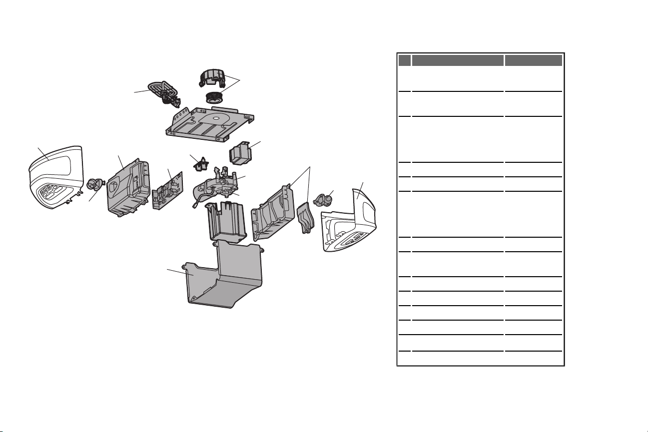
1
7
5
3
4
3
9
10
6
8
2
4
11
12
Repair Parts
Garage Door Opener Parts
DESCRIPTION PART NUMBER
1 Sprocket and Sprocket Cover
41C589-2
withScrews
2 End Panel withlabels, battery
41D7638
cover and light socket
3 LightLens
Model WD962KEV/KPEV
Model HD920EV
Model 349544
41D7570
41D7572
41D7571
4 LightSocket 41C279
5 Transformer 41A7635
6 Cover
Model WD962KEV/KPEV
Model HD920EV
Model 349544
41A7620-6
41A7620-3
41A7620
7 Motor and Travel Module 41D1739-1
8 End Panel withall labels and
light socket
9 Receiver LogicBoard 45DCT
10 Line Cord 41B135-1
11 Filter Board with Screws 41B7611
41D7639
12 Travel Module 41A7114-7
Not Shown
Wire Harness with Screws 41B7418
46
Page 47

Accessories
7702CB Outside Quick Release:
Required fora garage with NO
accessdoor.
8808CB
8810CB 10 Foot (3 m) Rail Extension:
8 Foot (2.4 m) RailExtension:
To allow an 8 foot(2.4 m) door to
open fully.
To allow a 10 foot(3 m) door to
open fully.
41A5281 ExtensionBrackets:
(Optional) For safetyreversing
sensor installation onto the wall or
floor.
PILCEV MyQ™ Remote Light Control:
Control home lighting and garage
doors with one remote.For use with
plug-in lamps.Synchronize to work
withMyQ™ compatible garage
door openers and remote controls.
CLLP1 Laser ParkingAssistant:
Park in the right spot everytime! A
laser beamisactivated byyour
garage door opener and projected
on to the dashboard of your vehicle
to guide perfectparking.
CLSS1 System Surge Protector:
The Garage Door Opener
Surge Protectoris designed to
protectChamberlain garage
door openers againstdamage
fromlightning and power
surges.Easyto install.
AGDMEV MyQ™ Garage Door Monitor:
Monitor open/closed statusfor
up to 4 MyQ™ compatible
garage door openers and
close them from anywhere in
the home.
41A6357-1 Standby Power System
Battery:
Provides backup power to the
garage door opener.
953EV Remote Control:
Workswith ALL Chamberlain openersfrom
1993-present. MyQ™ compatible. Includes
visorclip.
956EV Keychain Remote Control:
Workswith ALL Chamberlain openersfrom
1993-present. MyQ™ compatible. With key
ring.
940EV Wireless Keypad:
For use outside ofthe home toenable
accessto thegarage using a 4-digit PIN.
Workswith ALL Chamberlain openersfrom
1993-present. MyQ™ compatible.
47
Page 48

Warranty
CHAMBERLAIN®FIVE YEARLIMITED WARRANTY
LIFETIME MOTOR ANDBELTLIMITED WARRANTY
ONE YEARLIMITED WARRANTY FOR THEBATTERY BACKUP SYSTEM
The Chamberlain Group, Inc.®(“Seller”) warrants tothefirst retail purchaser of this product, for the residencein whichthis product is originally installed, that it is
free from defects in materials and/or workmanship for a period of five years from the date of purchase, except thatthemotor and belt are warranted to be free from
defects in materials and/or workmanship for thelifetime of the product while you own your residence,andthe Battery Backup Systemis warrantedto be freefrom
defects in materials and/or workmanship for a period of one year from the date of purchase. The proper operation of this productis dependent on your compliance
Contact Information
For installation and serviceinformation call:
1-800-528-9131
Before calling,please have themodel number of the garage
door opener. If you are calling about a Troubleshooting issue,
it is recommended thatyou have accessto your garage door
opener while calling. Ifyou are ordering a repair part please
have the following information:part number, part name, and
model number.
Address repair parts ordersto:
The ChamberlainGroup, Inc.
6050 S. Country ClubRoad
Tucson, AZ 85706
114A4242F All Rights Reserved
with theinstructions regarding installation, operation, andmaintenanceand testing. Failure to comply strictly with those instructions will void this limited warranty
in its entirety.
f, during the limited warranty period, this product appears to contain a defect covered by this limited warranty, call 1-800- 528-9131, toll free,before dismantling
this product. You will beadvisedof disassembly and shipping instructions when you call. Then sendtheproductor component, pre-paid and insured,as directed to
our service center for warranty repair. Please include a brief description of the problem and a dated proof-of-purchase receipt w ith any product returned for
warranty repair. Products returned to Seller for warranty repair, which upon receipt by Seller are confirmed to be defective andcovered by this limitedwarranty,
will be repaired or replaced (atSeller’s sole option) at no cost to you and returned pre-paid. Defective parts will be repaired or replaced with new or factoryrebuilt parts at Seller’s sole option. [You are responsible for any costs incurred inremovingand/or reinstalling the product or any component .]
ALL IMPLIED WARRANTIES FOR THE PROD UCT , INCLUDIN G BU T N OT LIMITED TO ANY IMPLIED WARR ANTIES OF MERC HAN TABILITY AND
FITNESS FOR A PA RTICULAR PUR POSE, ARE LIMITED IN DURATION TO THE APPLICABLE LIMITED WARRA NTY PERIOD SET FORTH ABOVE
FOR THE RELA TED COMPONENT( S), A ND NO IMPLIED WARR ANTIES WILL EXIST OR A PPLY AF TER SUCH PERIOD. Some States do not allow
limitations on how long an implied warranty lasts, so the above limitation may not apply to you. TH IS LIMITED WARRANTY DOES N OT C OVER
NON-DEFECT DAMAGE, DAMAGE CAUSED BY IMPROPER INSTA LLATION, OPERATION OR CAR E (INCLUD ING, BUT NOT LIMITED TO ABUSE,
MISUSE, FAILURE TO PROVIDE REA SONABLE AN D NECESSARY MAINTEN ANC E, UNAUTHORIZED REPAIRS OR ANY ALT ERATION S TO THIS
PRODUCT) , LABOR CHA RGES FOR REINSTALL ING A REPAIRED OR R EPLACED UN IT, REPLACEMENT OF CONSUMABLE ITEMS(E.G.,
BATTERIES IN REMOTE CONT ROL TRANSMITTERS AND LIGHT BU LBS), OR UNITS INSTALLED FOR NON- RESIDENT IAL USE. TH IS LIMITED
WARR ANTY DOES NOT COVER ANY PROBLEMS WITH, OR RELATING T O, THE GARAGE DOOR OR GARAGE DOOR HAR DWARE, INCLUDING
BUT NOT LIMITED TO T HE D OOR SPRINGS, DOOR ROLLERS, DOOR ALIGNMENT OR HINGES. THIS LIMITED WAR RAN TY ALSO DOES NOT
COVER ANY PROBL EMS CAU SED BY INTERFERENC E. UNDER NO C IRCUMSTANCES SHALL SELLER BE LIABLE FOR CONSEQUENTIAL,
INCID ENTAL OR SPECIAL DAMAGES ARISING IN CONNECTION WITH USE, OR INA BILITY TO USE, THIS PRODUCT. IN NO EVENT SHALL
SELLER’S LIABILITY FOR BREACH OF WARR ANTY, BREACH OF CONTRACT , NEGLIGENCE OR STR ICT LIABILITY EXCEED THE COST OF
THE PRODU CT COVERED HEREBY. NO PERSON IS AU THORIZED T O ASSUMEFOR US ANY OTHER LIABILITY IN CONN ECTION WITH THE
SALE OF THIS PROD UCT .
Somestates donotallow the exclusionor limitationofconsequential, incidental or special damages, so the above limitation or exclusion may not apply toyou.This
limited warranty gives youspecific legal rights, and you may also haveother rights, whichvary fromstateto state.
© 2012, The Chamberlain Group, Inc.
 Loading...