

Page 1
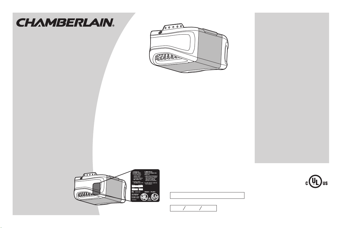
1/2 hp Belt Drive
Garage Door Opener
Models
• WD832KEV
• WD832KEVG
FOR RESIDENTIAL USE ONLY
■ Please read this manual and the enclosed safety materials carefully!
■ Fasten the manual near the garage door after installation.
■ The door WILL NOT CLOSE unless the Protector System
properly aligned.
■ Periodic checks of the garage door opener are required to ensure safe operation.
■ The model number label is located on the left side panel of your garage
door opener.
■ This garage door opener is compatible with MyQ
■ DO NOT install on a one-piece door if using devices or features providing unattended
close. Unattended devices and features are to be used ONLY with sectional doors.
Write down the following information
.
.
for future reference:
Serial Number:
Date of Purchase:
®
®
is connected and
and Security✚ 2.0™ accessories.
CONTENTS
Preparation .............................. 1-4
Assembly ................................. 5-9
Installation ............................ 10-19
Install the Door Control .............20-21
Install the Protector System
Power .................................. 26-27
Adjustments .......................... 28-30
Operation.................................. 31
Features ................................... 32
Door Control ..........................33-34
Remote Control ...................... 34-35
To Erase the Memory .................... 35
To Open the Door Manually ............ 36
Maintenance .............................. 37
Troubleshooting ...................... 38-39
Accessories ............................... 40
Warranty .................................. 41
Repair Parts .......................... 42-43
The Chamberlain Group, Inc.
Elmhurst, Illinois 60126-1196
®
...... 22-25
www.chamberlain.com
845 Larch Avenue
Page 2
Torsion
Spring
Extension
Spring
OR
Preparation
Safety Symbol and Signal Word Review
Thisgarage door opener has been designed and tested to offersafe serviceprovided it is installed,
operated, maintained and tested in strictaccordance with the instructions and warnings contained inthis
manual.
When you see these SafetySymbols and Signal Words on the following pages, theywill alert you to the
possibilityof serious injury or death if you do not complywith the warnings thataccompany them. The
hazard may come from something mechanical or from electricshock.Read the warnings carefully.
Mechanical
Electrical
When you see thisSignal Word on the following pages, it will alert you to the possibility of damage to
your garage door and/or the garage door opener if you do not complywith the cautionary statementsthat
accompanyit. Read them carefully.
Unattended Operation
The Timer-to-Close (TTC)feature, the MyQ®Smartphone Control app, and MyQ®Garage Door and
Gate Monitor are examples of unattended close and are to be used ONLY with sectional doors . Any
device or feature thatallows the door to close withoutbeing in the line of sight of the door is considered
unattended close.The Timer-to-Close (TTC) feature,the MyQ®Smartphone Control, and any other
MyQ®devicesare to be used ONLY with sectional doors.
Check the Door
To prevent possible SERIOUS INJURY or DEATH:
l ALWAYS call a trained door systemstechnician if garage door binds,sticks,or is out of balance.
An unbalanced garage door may NOT reverse when required.
l NEVER tryto loosen, moveor adjustgarage door, door springs, cables,pulleys,bracketsor their
hardware, ALL of which are under EXTREME tension.
l Disable ALL locksand remove ALL ropes connected to garage door BEFOREinstallation and
operating garage door opener to avoid entanglement.
l DO NOTinstall on a one-piece door if using devicesor features providing unattended close.
Unattended devicesand features are to be used ONLY with sectional doors.
To prevent damage to garage door and opener:
l ALWAYS disable locksBEFORE installing and operating the opener.
l ONLY operate garage door opener at120 V, 60 Hz to avoid malfunction and damage.
Before you begin:
1. Disable locks and remove any ropes connected to the garage door.
2. Liftthe door halfwayup. Release the door. Ifbalanced, it should stay
in place, supported entirely by itssprings.
3. Raiseand lower the door to check for binding or sticking. If your door
binds, sticks,or is out of balance,call a trained door systems
technician.
4. Checkthe seal on the bottomof the door. Any gap between the floor
and the bottom of the door mustnot exceed 1/4 inch (6 mm).
Otherwise,the safetyreversal systemmay not work properly.
5. The opener should beinstalled above the center of the door. Ifthere
is a torsion spring or center bearing plate in the way of the header
bracket,it may be installed within 4feet(1.2 m) to the leftor right of
the door center. See page11.
1
Page 3
3/16
7/16
1/2
5/32
5/16
5/8
9/16
1/4
7/16
Preparation
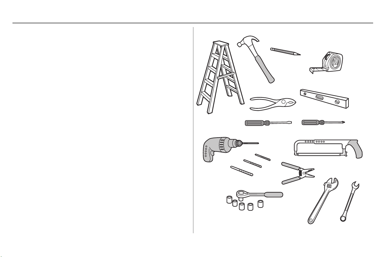
Additional Items You May Need:
Survey your garage area to see if you will need any of the following items:
n (2) 2X4 PIECES OF WOOD
Maybe used to fasten the header bracketto the structural supports.Also used to position the
garage door opener during installation and for testingthe safetyreversing sensors.
n SUPPORT BRACKET AND FASTENING HARDWARE
Mustbe used if you have a finished ceiling in your garage.
n EXTENSION BRACKETS (MODEL 041A5281-1) ORWOOD BLOCKS
Depending upon garage construction, extension bracketsor wood blocks may be needed to
install the safetyreversing sensor.
n FASTENING HARDWARE
Alternate floor mounting of the safety reversing sensor will require hardware notprovided.
n OUTSIDE QUICK RELEASE (MODEL 7702CB)
Required for a garage with NO accessdoor.
n DOOR REINFORCEMENT
Required if you have a lightweightsteel,aluminum,fiberglass or glass panel door.
n RAILEXTENSION KIT
Required if your garage door is more than 7 feet (2.13 m) high.
Tools Needed
2
Page 4
N
A
B
C
H
K
J
O
I
D
E
F
G
L
M
P
Preparation
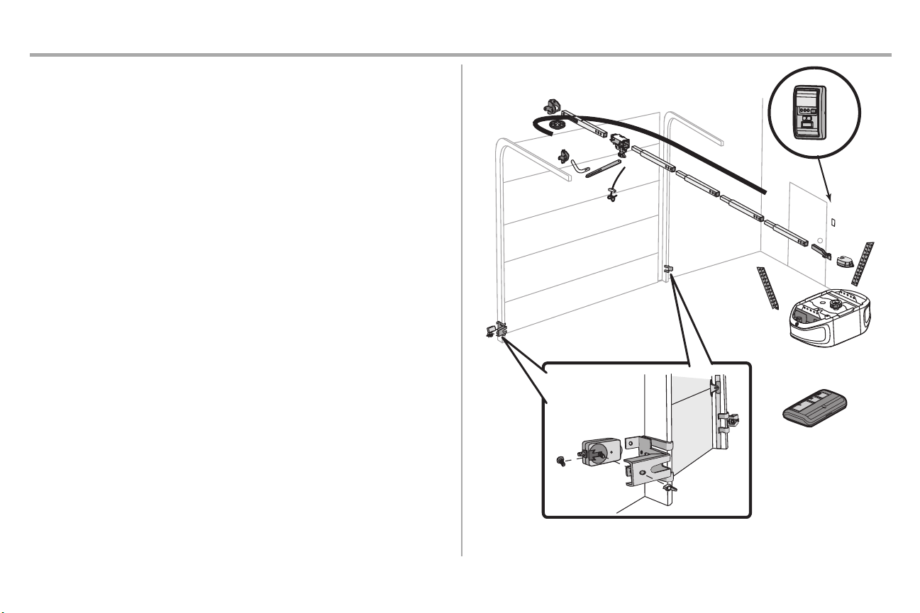
Carton Inventory
Your garage door opener ispackaged in one carton which contains the motor unit and all parts
illustrated below.Accessoriesvary depending on the garage door opener model purchased.Depending
on your model, other accessories may be included with your garage door opener. Instructions for these
accessories will be attached to the accessoryand are notincluded in this manual. Save the carton and
packing material until the installation and adjustmentis complete.The images throughout this manual
are for reference only and your productmay look different.
A. Header bracket
B. Pulley
C. Door bracket
D. Curved door arm
E. Straight door arm
(Packaged inside front rail section)
F. Trolley
NOTE: Be sure to assemble the trolley before sliding ontorail.
G. Emergencyrelease rope and handle
H. Rail (1 front and 4 center sections)
I. Hanging brackets (2)
(Packaged inside the front rail section)
J. Garage door opener (motor unit)
K. Sprocketcover and screws
L. “U” bracket
M. Belt
N. Door control
O. Remote control (2)
P. The Protector System
Safetyreversing sensors with 2 conductor white and white/blackwire attached:Sending Sensor
(1), Receiving Sensor (1), and Safety Sensor Brackets(2)
NOT SHOWN
White and red/white wire
Owner's manual
Hardware
®
3
Page 5
Clevis Pin 5/16"x1-1/2"
Ring Fastener (3)
Hex Bolt 5/16"-18x7/8" (4)
Lock Washer
5/16"-18 (5)
Nut
5/16"-18 (6)
Self-Threading Screw
1/4"-14x5/8" (2)
Clevis Pin 5/16"x1"
Clevis Pin 5/16"x1-1/4"
Carriage Bolt
1/4"-20x1/2" (2)
Wing Nut 1/4"-20 (2)
ASSEMBLY INSTALLATION
Screw 6ABx1" (2)
Drywall Anchors (2)
Screw 6-32x1" (2)
DOOR CONTROL
Insulated
Staples
(
Not Shown)
Lag Screw 5/16"-9x1-5/8" (4)
Hex Screw
#8x3/8" (2)
(packed with the
sprocket cover)
Bolt
1/4"-20x1-3/4"
Lock Nut
1/4"-20
Bolt
Nut 3/8"
Lock Washer 3/8"
Master Link
Spring
Trolley Nut
Threaded
Shaft
with
Preparation
Hardware
4
Page 6
Assembly
To garage
door opener
(TO MOTOR UNIT)
Front Rail
Section
(TO DOOR)
“U” Bracket
Outer Trolley
Inner Trolley
Wear Pads
SLIDE TO STOPS
ON TOP AND
SIDES OF
“U” BRACKET
Trolley
Rail Tab
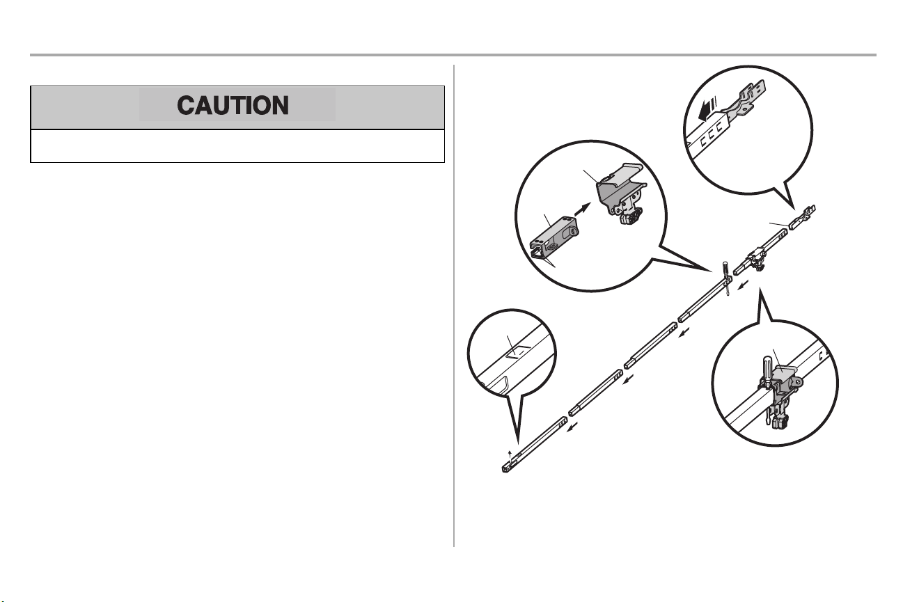
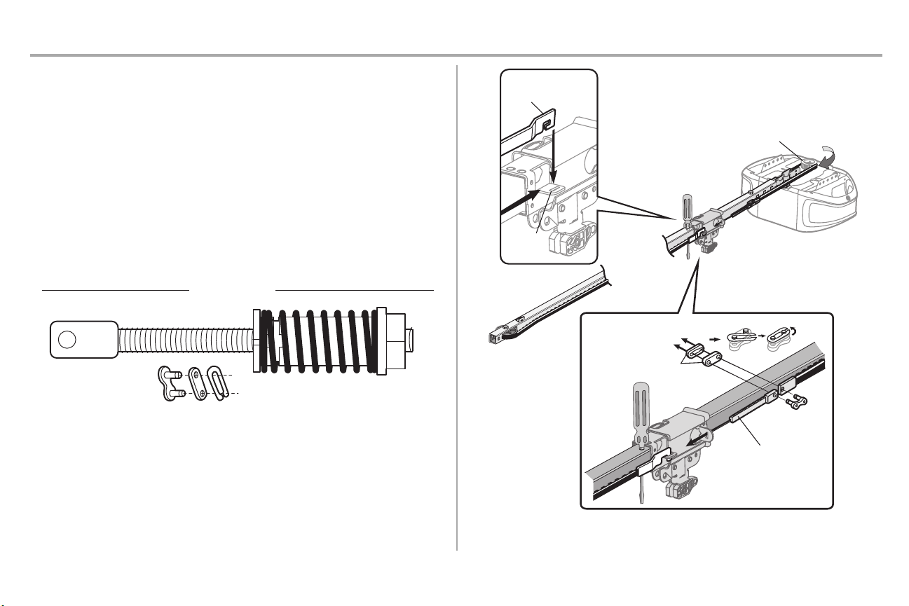
STEP 1 Assemble the rail and install the trolley
To prevent INJURYfrom pinching, keep hands and fingers away from the joints while assembling the
rail.
To avoid installation difficulties, do not run the garage door openeruntilinstructed to do so.
The front rail hasa cut out “window” at the door end. The rail tab MUST be on top of the rail when
assembled.
1. Remove the straightdoor arm and hanging bracketpackaged inside the front rail and set aside
for Installation Step 5 and 9. NOTE: To prevent INJURY while unpacking the rail carefully remove
the straight door arm stored within the rail section.
2. Align the rail sections on aflat surface as shown and slide the tapered ends into the larger ones.
Tabs along the side will lock into place.
3. Place the motor unit on packing material to protectthe cover, and rest the backend ofthe rail on
4. Asa temporary stop,insert a screwdriver into the hole in the second rail section from the motor
5. Checkto be sure there are 4 plastic wear pads inside the inner trolley. Ifthey became loose
6. Slide the trolley assemblytoward the screwdriver as shown.
7. Slide the rail onto the “U” bracket, until it reaches all the stopson the top and sides of the “U”
top.For convenience, put a support under the front end of the rail.
unit,as shown.
during shipping, checkall packing material. Snap them back into position as shown.
bracket.
5
Page 7
Assembly
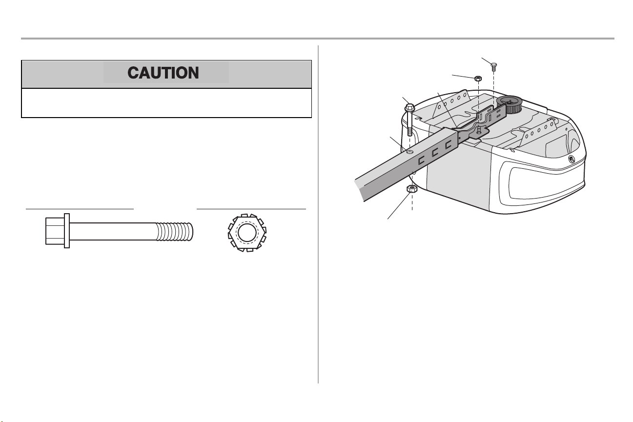
HARDWARE
Bolt 1/4"-20x1-3/4"
Lock Nut 1/4"-20
“U” Bracket
Cover Protection
Bolt
Hole
Bolt 1/4"-20x1-3/4"
Lock Nut 1/4"-20
Lock Nut (Mounted in
the garage door opener)
Bolt (Mounted in the
garage door opener)
STEP 2 Fasten the rail to the motor unit
To avoid SERIOUS damage to garage door opener, use ONLY those bolts/fastenersmounted in the
top of the opener.
1. Insert a 1/4"-20x1-3/4" bolt into the cover protection bolt hole on the back end of the rail as
shown.Tighten securely with a 1/4"-20 lock nut. DO NOT overtighten.
2. Remove the bolt and nut from the top of the motor unit.
3. Use the carton to support the front end of the rail.
4. Place the “U” bracket,flat side down onto the motor unit and align the bracket holes withthe bolt
holes.
5. Fasten the “U” bracketwith the previouslyremoved bolt and lock nut;DO NOT use any power
tools.The use of power tools may permanentlydamage the garage door opener.
6
Page 8
Assembly
HARDWARE
Bolt
Nut 3/8"
Lock Washer 3/8"
Rail
Trolley Connector
Bolt
Lock Washer 3/8"
Nut
3/8"
Rail Tab
CORRECT
INCORRECT
Rail Tab
Idler Pulley
Grease Inside Pulley
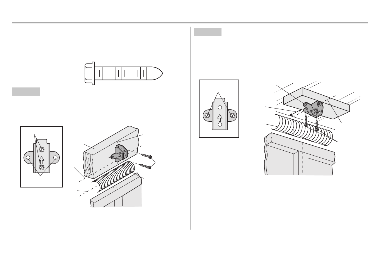
STEP 3 Install the idler pulley
1. Lay the belt beside the rail, as shown. Grasp the end with the hooked trolley connector and pass
approximately 12" (30 cm) of belt through the window. Keep the ribbed side toward the rail, and
allow it to hang until AssemblyStep 4.
2. Remove the tape from the idler pulley. The inside center should be pre-greased. Ifdry, regrease
to ensure proper operation.
3. Place the idler pulley into the window as shown.
4. Insert the idler bolt from the top through the rail and pulley. Tighten with a 3/8" lock washer and
nut underneath the rail until the lock washer is compressed.
5. Rotate the pulley to be sure it spins freely.
6. Locatethe rail tab. The rail tab is between the idler bolt and the trolley in the front rail section.Use
a flathead screwdriverand lift the rail tab until the tab is vertical (90º).
7
Page 9
Assembly
HARDWARE
Master
Link
Threaded Shaft with Spring Trolley Nut
Sprocket
Figure 3
Threaded Shaft
Master Link
Figure 2
Trolley Connector
Figure 1
Retaining
Slot
STEP 4 Install the belt
1. Pull the belt around the idler pulley and toward the trolley.The ribbed side mustcontactthe
pulley.
2. Hookthe trolley connector into the retaining slot on the trolley as shown (Figure 1).
3. With the trolley against the screwdriver, dispense the remainder of the belt along the rail
lengthtowardthe motor unit and around the sprocket(Figure 2). The sprocket teeth mustengage
the belt.
4. Checkto make sure the belt is not twisted.Connect the trolley threaded shaftwith the master link
(Figure 3).
l Push pins of master link bar through holesin end of belt and trolley threaded shaft.
l Push masterlink cap over pins and pastpin notches.
l Slide the closed end of the clip-on spring over one of the pins. Push the open end ofthe
clip-on spring onto the other pin.
5. Remove the spring trolley nut fromthe threaded shaft.
6. Insert the trolley threaded shaftthrough the hole in the trolley.
8
Page 10
Assembly
Nut Ring
BEFORE
1"
(2.5
cm)
Nut Ring
AFTER
1-1/4"
(3.18 cm)
Spring
Trolley Nut
Nut Ring Slot
Hex Screw #8x3/8"
(Packed with the
sprocket cover)
HARDWARE
Hex Screw #8x3/8"
Sprocket Cover
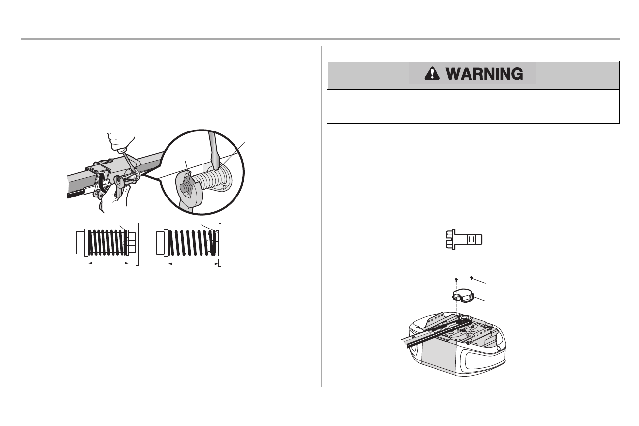
STEP 5 Tighten the belt
1. Byhand, thread the spring trolley nut on the threaded shaft until it is finger tight against the
trolley.Do not use any tools.Remove the screwdriver.
2. Insert a flathead screwdrivertip into one of the nut ring slots and brace it firmlyagainstthe trolley.
3. Tightenthe spring trolley nut with an adjustable wrench or a 7/16" open end wrench about a
quarter turn until the spring releasesand snaps the nut ring againstthe trolley. This setsthe
spring to optimumbelt tension.
STEP 6 Install the sprocket cover
To avoid possible SERIOUS INJURY to finger from moving garage door opener:
l ALWAYS keep hand clear of sprocketwhile operating opener.
l Securely attach sprocketcover BEFORE operating.
1. Position the sprocketcover over the sprocketas shown and fasten to the mounting plate with
8x3/8"hex screwsprovided.
You have now finished assemblingyourgarage dooropener. Please read the following warnings
beforeproceedingto the installationsection.
9
Page 11
Installation
IMPORTANT INSTALLATION INSTRUCTIONS
To reduce the risk of SEVERE INJURY or DEATH:
1. READAND FOLLOW ALL INSTALLATIONWARNINGS AND INSTRUCTIONS.
2. Install garage door opener ONLY on properly balanced and lubricated garage door. An
improperly balanced door may NOTreverse when required and could result in SEVERE
INJURYor DEATH.
3. ALL repairs to cables, spring assembliesand other hardware MUSTbe made bya trained door
systemstechnician BEFORE installing opener.
4. Disable ALL locksand remove ALL ropes connectedto garage door BEFORE installing opener
to avoid entanglement.
5. Install garage door opener 7 feet (2.13 m) or more above floor.
6. Mountthe emergency release within reach, but at least6 feet (1.83 m) above the floor and
avoiding contactwith vehiclesto avoid accidental release.
7. NEVER connect garage door opener to power source until instructed to do so.
8. NEVER wear watches,rings or loose clothing while installing or servicing opener. They could be
caught in garage door or opener mechanisms.
9. Install wall-mounted garage door control:
l within sight of the garage door.
l out of reach of children at minimum height of 5 feet (1.5m).
l away from ALL moving partsof the door.
10. Placeentrapment warning label on wall nextto garage door control.
11. Placemanual release/safetyreverse testlabel in plain view on inside of garage door.
12. Upon completion of installation,testsafetyreversal system.Door MUSTreverse on contact with a
1-1/2" (3.8 cm)high object(or a 2x4 laid flat) on the floor.
13. To avoid SERIOUS PERSONAL INJURY or DEATH from electrocution,disconnectALL electric
power BEFORE performing ANY service or maintenance.
14. DO NOT installon aone-piece door if using devices or features providing unattended close.
Unattended devicesand features are to be used ONLY with sectional doors.
10
Page 12
Installation
Header Wall
Vertical Centerline of Garage Door
2x4
Structural
Supports
Level
(Optional)
Unfinished
Ceiling
2x4
OPTIONAL CEILING MOUNT
FOR HEADER BRACKET
Sectional door with curved track
Header Wall
Track
2" (5 cm)
Highest
Point of
Travel
Door
One-piece door with horizontal track
Header Wall
Track
2" (5 cm)
Highest
Point of
Travel
Door
One-piece door without track:
jamb
hardware
Header Wall
8" (20
cm)
Highest
Point of
Travel
Door
Jamb
Hardware
One-piece door without track:
pivot hardware
Header Wall
8" (20
cm)
Highest
Point of
Travel
Door
Pivot
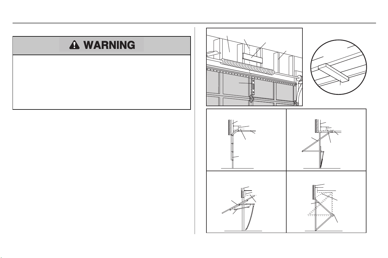
STEP 1 Determine the header bracket location
To prevent possible SERIOUS INJURY or DEATH:
l Header bracket MUST be RIGIDLY fastened to structural support on header wall or ceiling,
otherwise garage door might NOTreverse when required. DO NOT installheader bracket over
drywall.
l Concreteanchors MUST be used if mounting header bracket or 2x4 into masonry.
l NEVER tryto loosen, moveor adjustgarage door, springs,cables, pulleys,brackets,or their
hardware, ALL of which are under EXTREME tension.
l ALWAYS call a trained door systemstechnician if garage door binds,sticks,or is out of balance.
An unbalanced garage door might NOT reverse when required.
Installation procedures vary according to garage door types.Follow the instructionswhich apply to your
door.
1. Closethe door and mark the inside verticalcenterline of the garage door.
2. Extend the line onto the header wall above the door.You can fasten the header bracketwithin 4
feet(1.22 m) of the leftor right of the door center only if a torsion spring or center bearing plate is
in the way;or you can attach it to the ceiling (see page 12) when clearance is minimal. (It maybe
mounted on the wall upside down if necessary,to gain approximately1/2" (1 cm).Ifyou need to
install the header bracketon a 2x4 (on wall or ceiling), use lag screws(not provided) to securely
fasten the 2x4 to structural supportsas shown here and on page 12.
3. Open your door to the highest point of travel as shown. Draw an intersecting horizontal line on
the header wall 2" (5 cm) above the high point :
l 2" (5 cm) above the high point for sectional door and one-piece door with track.
l 8" (20 cm) above the high point for one-piece door without track.
Thisheight will provide travel clearance for the top edge of the door. NOTE: Ifthe total number of inches
exceeds the height available in your garage, use the maximumheight possible, or refer to page 12 for
ceiling installation.
11
Page 13
Installation
HARDWARE
Lag Screw 5/16"-9x1-5/8"
UP
Wall Mount
Optional Mounting
Holes
Vertical
Centerline of
Garage Door
(Header Wall)
Header
Bracket
2x4 Structural
Support
Door Spring
(Garage Door)
Highest Point
of Garage
Door Travel
Horizontal
Line
Lag Screw
5/16"-9x1-5/8"
UP
(Header Wall)
Ceiling Mounting
Holes
(Finished
Ceiling)
Vertical
Centerline of
Garage Door
Header
Bracket
6" (15 cm)
Maximum
Door Spring
(Garage Door)
Lag Screw
5/16"-9x1-5/8"
STEP 2 Install the header bracket
You can attach the header bracketeither to the wall above the garage door,or to the ceiling. Follow the
instructions which will work best for your particular requirements.Do not install the header bracketover
drywall.If installing into masonry, use concrete anchors (not provided).
OPTION A WALL INSTALLATION
1. Centerthe bracket on the verticalcenterline with the bottomedge ofthe bracketon the horizontal
line as shown (with the arrow pointing toward the ceiling).
2. Markthe vertical set of bracketholes. Drill 3/16" pilot holes and fasten the bracketsecurely to a
structural support withthe hardware provided.
OPTION B CEILING INSTALLATION
1. Extend the vertical centerline ontothe ceiling as shown.
2. Centerthe bracket on the verticalmark, no more than 6" (15cm) from the wall. Makesure the
arrow is pointing away fromthe wall. The bracketcan be mounted flush againstthe ceiling when
clearance is minimal.
3. Markthe side holes. Drill 3/16" pilot holes and fasten bracketsecurely to a structural support with
the hardware provided.
12
Page 14
Installation
HARDWARE
Clevis Pin 5/16"x1-1/2"
Ring Fastener
Clevis Pin
5/16"x1-1/2"
Ring Fastener
One-piece
door without
tracks
All other door types
Connected Disconnected
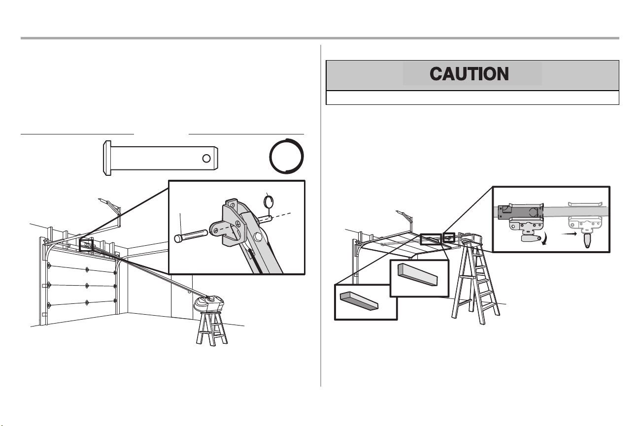
STEP 3 Attach the rail to the header bracket
1. Position the opener on the garage floor below the header bracket.Use packing material as a
protective base.
NOTE: If the door spring is in the way, you will need help. Have someone hold the opener
securely on a temporary support to allow the rail to clear the spring.
2. Position the rail bracket against the header bracket.
3. Align the bracket holes and join with a clevis pin as shown.
4. Insert a ring fastener to secure.
STEP 4 Position the garage door opener
To prevent damage to garage door,rest garage door opener rail on 2x4placed on top sectionof door.
1. Remove the packing material and lift the garage door opener onto a ladder.
2. Fullyopen the door and place a 2x4 (laid flat) under the rail. For one-piece doors withouttracks,
lay the 2x4 on it's side.
NOTE: A 2x4 is ideal for setting the distancebetween the rail and the door. If the ladder is not tall
enough you will need help atthis point. If the door hits the trolley when it is raised, pull the trolley release
arm down to disconnectthe inner and outer trolley. Slide the outer trolley toward the garage door
opener. The trolley can remain disconnected until instructed.
13
Page 15

Installation
Finished
Ceiling
Unfinished
Ceiling
HARDWARE
Hex Bolt 5/16"- 18x7/8"
Nut 5/16"-18
Lock
Washer
5/16"-18
Lag Screw 5/16"-9x1-5/8"
Finished
Ceiling
(not provided)
(not provided)
Lag Screw
5/16"9x1-5/8"
Lag Screw
5/16"9x1-5/8"
1
2
3
(not
provided)
Hex Bolt
5/16"- 18x7/8"
Nut 5/16"-18
Lock
Washer
5/16"-18
4
5
6
STEP 5 Hang the garage door opener
To avoid possible SERIOUS INJURY from a falling garage door opener, fastenit SECURELY to
structural supports of the garage. Concrete anchors MUST be used if installing ANY bracketsinto
masonry.
Hanging the garage door opener will vary depending on your garage. Below are three example
installations.Your installation may be different.For ALL installationsthe garage door opener MUST be
connected to structural supports. The instructions illustrate one of the examples below.
1. On finished ceilings,use the lag screwsto attach a support bracket(not provided) to the structural
supportsbefore installing the garage door opener.
2. Makesure the garage door opener is aligned with the header bracket.Measure the distance
fromeach side of the garage door opener to the support bracket.
3. Cutboth pieces of the hanging bracketto required lengths.
4. Attach the end of each hanging bracket to the support bracketwith appropriate hardware (not
provided).
5. Attach the garage door opener to the hanging bracketswiththe hex bolts,lock washers,and
nuts.
6. Remove the 2x4 and manually close the door. Ifthe door hits the rail, raise the header bracket.
14
Page 16

Installation
or
or
STEP 6 Install the light bulbs
To prevent possible OVERHEATING of the end panel or light socket:
l UseONLY A19 incandescent (100W maximum)or compact fluorescent (26W maximum)light
bulbs.
l DO NOTuse incandescent bulbs larger than 100W.
l DO NOTuse compactfluorescent light bulbs larger than 26W (100W) equivalent.
l DO NOTuse halogen bulbs.
l DO NOTuse short neck or specialtylight bulbs.
1. Pull on the top sides of the light lens and rotate the light lens down.
2. Insert an A19 incandescent(100W maximum) or compactfluorescent(26W,100W equivalent)
light bulb into the light socket.
3. Rotate the lens up to close.
NOTE: Do not use halogen, short neck,or specialty light bulbs as these may overheat the end panel or
light socket. Do not use LED bulbs as they may reduce the range or performance of your remote controls.
STEP 7 Attach the emergency release rope and handle
To prevent possible SERIOUS INJURY or DEATH from a falling garage door:
l Ifpossible, use emergency release handle to disengage trolley ONLY when garage door is
CLOSED. Weak or broken springs or unbalanced door could result in anopen door falling
rapidly and/or unexpectedly.
l NEVER use emergency release handle unlessgarage doorwayis clear of persons and
obstructions.
l NEVER use handle to pull door open or closed. Ifrope knot becomesuntied, you could fall.
1. Insert one end of the emergencyrelease rope through the handle. Make sure that “NOTICE” is
right side up. Tie a knot at least 1 inch (2.5 cm) from the end of the emergency release rope.
2. Insert the other end of the emergency release rope through the hole in the trolley release arm.
Mount the emergencyrelease within reach, but at least 6 feet (1.83 m) above floor, avoiding
contactwith vehicles to preventaccidental release and secure witha knot.
NOTE: If it is necessaryto cutthe emergency release rope, seal the cut end with a match or lighter to
prevent unraveling. Ensure the emergencyrelease rope and handle are above the top of all vehicles to
avoid entanglement.
15
Page 17

Installation
Self-Threading Screw
1/4"-14x5/8"
HARDWARE
FIGURE 1
FIGURE 3
FIGURE 4
FIGURE 2
Vertical
Reinforcement
Vertical Centerline
of Garage Door
UP
Door Bracket
Vertical Reinforcement
Vertical Centerline
of Garage Door
Hardware
(not provided)
Door Bracket
UP
Vertical
Centerline
of Garage
Door
UP
Vertical Centerline of
Garage Door
Hardware
(not provided)
UP
Inside Edge of Door or
Reinforcement Board
Self-Threading Screw
1/4"-14x5/8"
Self-Threading
Screw
1/4"-14x5/8"
STEP 8 Install the door bracket
Fiberglass,aluminum or lightweight steel garage doorsWILLREQUIRE reinforcement BEFORE
installation of door bracket.Contactthe garage door manufacturer or installing dealer for opener
reinforcementinstructionsor reinforcementkit.Failure to reinforce the top section as required
according to the door manufacturer mayvoid the door warranty.
A horizontal and vertical reinforcement is needed for
lightweight garage doors (fiberglass,aluminum, steel,
doors with glasspanel, etc.) (not provided). A horizontal
reinforcementbrace should be long enough to be
secured to two or three vertical supports.A vertical
reinforcementbrace should cover the height of the top
panel. Contactthe garage door manufacturer or installing
dealer for opener reinforcementinstructions or
reinforcementkit.
NOTE: Many door reinforcementkitsprovide for direct attachment of the clevis pin and door arm. In this
case you will not need the door bracket;proceed to the next step.
OPTION A SECTIONAL DOORS
1. Centerthe door bracket on the previously marked vertical centerline used for the header bracket
2. Position the top edge ofthe bracket2"-4" (5-10 cm) below the top edge of the door, OR directly
3. Mark,drill holes and install as follows,depending on your door’s construction.
installation.Note correctUP placement,as stamped inside the bracket.
below any structural support acrossthe top of the door.
Metal or light weight doors using a vertical angle iron brace between the doorpanelsupport and
the door bracket:
l Drill 3/16" fastening holes.Secure the door bracket using the two 1/4"-14x5/8" self threading
screws.(Figure 1)
l Alternately,use two 5/16"-18x2" bolts,lock washers and nuts(not provided). (Figure 2)
Metal,insulated orlight weight factory reinforced doors:
l Drill 3/16" fastening holes.Secure the door bracket using the self-threading screws.(Figure 3)
Wood Doors:
l Usetop and bottomor side to side door bracketholes. Drill 5/16" holes through the door and
secure bracketwith 5/16"-18x2" carriage bolts,lock washersand nuts(not provided). (Figure 4)
NOTE: The 1/4"-14x5/8" self-threading screws are not intended for use on wood doors.
16
Page 18

Installation
For a door with no exposed
framing, or for the optional
installation, use lag screws
5/16"x1-1/2" (not provided)
to fasten the door bracket.
Vertical
Centerline
of Garage
Door
Optional
Placement
of Door
Bracket
Door Bracket
Header Bracket
Header Wall
2x4 Support
(Finished Ceiling)
Door
Bracket
Top
of Door
(Inside Garage)
Top Edge of
Door
Optional
Placement
Optional
Placement
Top Edge
of Door
Top of Door
(Inside Garage)
Door
Bracket
Hardware
(not provided)
Hardware
(not provided)
Metal Door
Wood Door
Self-Threading
Screw 1/4"-14x5/8"
STEP 8 Install the door bracket (continued)
OPTION B ONE-PIECE DOORS
1. Centerthe door bracket on the top of the door, in line with the header bracket as shown.
2. Markeither the left and right, or the top and bottom holes.
Metal Doors:
l Drill 3/16" pilot holes and fasten the bracketwith the self-threading screwsprovided.
Wood Doors:
l Drill 5/16" holes and use 5/16"-18x2" carriage bolts,lock washersand nuts(not provided) or
5/16"x1-1/2"lag screws(not provided) depending on your installation needs.
NOTE: The door bracketmay be installed on the top edge ofthe door if required for your installation.
(Refer to the dotted line optional placement drawing.)
17
Page 19

Installation
HARDWARE
Hex Bolt 5/16"-18x7/8"
Nut 5/16"-18
Lock Washer 5/16" -18
Clevis Pin 5/16"x1" Clevis Pin 5/16"x1-1/4"
Ring
Fastener
Straight
Door Arm
Curved
Door
Arm
(Groove
facing
out)
CORRECT
Straight
Door
Arm
Curved
Door
Arm
INCORRECT
Lock Washer
5/16" -18
Nut
5/16"-18
Hex Bolt 5/16"-18x7/8"
Clevis Pin 5/16"x1-1/4"
Ring Fastener
Clevis Pin
5/16"x1"
STEP 9 Connect the door arm to the trolley
Installation will vary according to the garage door type.Follow the instructions which apply to your door.
OPTION A SECTIONAL DOORS
IMPORTANT: The groove on the straight door arm MUST faceaway from the curved door arm.
1. Closethe door. Disconnectthe trolley by pulling the emergencyrelease handle.
2. Attach the straight door arm to the outer trolley using the clevis pin. Secure with the ring fastener.
3. Attach the curved door arm to the door bracketusing the clevispin. Secure with the ring fastener.
4. Bring arm sectionstogether. Find twopairs of holes that line up and join sections.Select holes as
far apart as possible to increase door arm rigidity and attach using the bolts,nuts,and lock
washers.
5. Pull the emergency release handle toward the garage door opener until the trolley release arm
is horizontal.The trolley will re-engage automaticallywhen the garage door opener is activated.
NOTE: If the holes in the curved door armand the straight door arm do notalign, reverse the straight
door arm, selecttwo holes (as far apart as possible) and attach using bolts , nuts,and lock washers . If the
straight door armis hanging down too far, you may cut 6 inches (15 cm) from the solid end.
18
Page 20

Installation
HARDWARE
Hex Bolt 5/16"-18x7/8"
Nut 5/16"-18
Lock Washer 5/16" -18
Clevis Pin 5/16"x1" Clevis Pin 5/16"x1-1/4"
Ring
Fastener
One-Piece Door without Track
One-Piece Door with Track
Straight
Door Arm
Curved
Door
Arm
(Groove
facing out)
CORRECT
INCORRECT
Straight
Door
Arm
Curved
Door
Arm
Ring
Fastener
Ring Fastener
Nut 5/16"-18
Nut 5/16"-18
Ring
Fastener
Ring Fastener
Lock Washer 5/16" -18
Lock Washer 5/16" -18
Clevis Pin 5/16"x1-1/4"
Clevis Pin
5/16"x1-1/4"
Hex Bolt 5/16"-18x7/8"
Hex Bolt 5/16"-18x7/8"
Clevis Pin
5/16"x1"
Clevis Pin
5/16"x1"
STEP 9 Connect the door arm to the trolley (continued)
OPTION B ONE-PIECE DOORS
IMPORTANT: The groove on the straight door arm MUST faceaway from the curved door arm.
1. Closethe door. Disconnectthe trolley by pulling the emergencyrelease handle.
2. Fasten the straightdoor armand the curved door armtogether to the longest possible length
3. Attach the straight door arm to the door bracket using the clevis pin. Secure with the ring fastener.
4. Attach the curved door arm to the trolley using the clevispin. Secure with the ring fastener.
5. Pull the emergency release handle toward the garage door opener until the trolley release arm
(with a 2 or 3 hole overlap) using the bolts,nuts, and lock washers.
is horizontal.
19
Page 21

Installation
HARDWARE
Screw
6ABx1"
(2)
Drywall
Anchors
(2)
Screw
6-32x1" (2)
7/16" (11 mm)
Wall
1
2 3
DRYWALL
GANG BOX
6ABx1"
6-32x1"
Drywall Anchor
4-5
6
6-32x1"
GANG BOX
8
DRYWALL
6ABx1"
Drywall Anchor
7
STEP 10 Install the door control
To prevent possible SERIOUS INJURY or DEATH from electrocution:
l Be sure power is NOT connected BEFORE installing door control.
l ConnectONLY to 12 VOLT low voltage wires.
To prevent possible SERIOUS INJURY or DEATH from a closing garage door:
l Install door control within sight of garage door, out of reach of children at a minimum height of 5
feet(1.5 m), and away from ALL moving parts of door.
l NEVER permit children to operate or play with door control push buttonsor remote control
transmitters.
l Activate door ONLY when itcan be seen clearly, is properly adjusted, and there are no
obstructions to door travel.
l ALWAYS keep garage door in sight until completelyclosed. NEVER permit anyone to crosspath
of closing garage door.
INTRODUCTION
Compatible with MyQ®enabled accessories, see page 40. Your garage door opener is compatible with
up to 2 MyQ®door controls.NOTE: Older Chamberlain door controls and third party products are not
compatible.
Install the door control within sight of the door at a minimum height of 5 feet (1.5 m) where small children
cannot reach, and away fromthe moving parts of the door. For gang box installations it is not necessary
to drill holes or installthe drywall anchors. Usethe existing holes in the gang box.
NOTE: Your product may look different than the illustrations.
1. Strip 7/16 inch (11 mm) of insulation fromone end of the wire and separate the wires.
2. Connectone wire to each of the two screwson the back of the door control.The wires can be
connected to either screw.If your garage is pre-wired for the door control choose any two wires to
connect,note which wires are used so the correct wires are connected to the garage door
opener in a later step.
3. Markthe location of the bottommounting hole and drill a 5/32 inch (4 mm) hole.
4. Install the bottomscrew,allowing 1/8 inch (3 mm) to protrude from the wall.
5. Position the bottom hole of the door control over the screw and slide down into place.
6. Liftthe push bar up and mark the top hole.
7. Remove the door control from the wall and drill a 5/32 inch (4 mm) hole for the top screw.
8. Position the bottom hole of the door control over the screw and slide down into place. Attachthe
top screw.
20
Page 22

Installation
HARDWARE
Insulated
Staple
(Not Shown)
RED
WHITE
WHITE
GREY
7/16" (11 mm)
2
3
1
Staple
STEP 11 Wire the door control to the garage door opener
1. Run the white and red/whitewire from the door control to the garage door opener. Attach the
wire to the wall and ceiling with the staple (not applicable for gang boxor pre-wired installations).
Do not pierce the wire withthe staple as thismay cause a short or an open circuit.
2. Strip 7/16 inch (11 mm) of insulation fromthe end of the wire near the garage door opener.
3. Connectthe wire to the red and white terminals on the garage door opener. Ifyour garage is prewired make sure you use the same wires that are connected to the door control. To insert or
release wires fromthe terminal, push in the tab with screwdriver tip.
STEP 12 Attach the warning labels
1. Attach the entrapment warning label on the wall near the door control withtacksor staples.
2. Attach the manual release/safetyreverse test label in a visible location on the inside of the
garage door.
21
Page 23

Installation
Safety Reversing Sensor
6" (15
cm) max. above floor
Invisible Light Beam
Protection Area
Facing the door from inside the garage
HARDWARE
Carriage Bolt
1/4"-20x1/2"
Wing Nut
1/4"-20
No more
than 6 inches
(15 cm)
Carriage Bolt
1/4"-20x1/2"
Wing Nut
1/4"-20
1
2
3
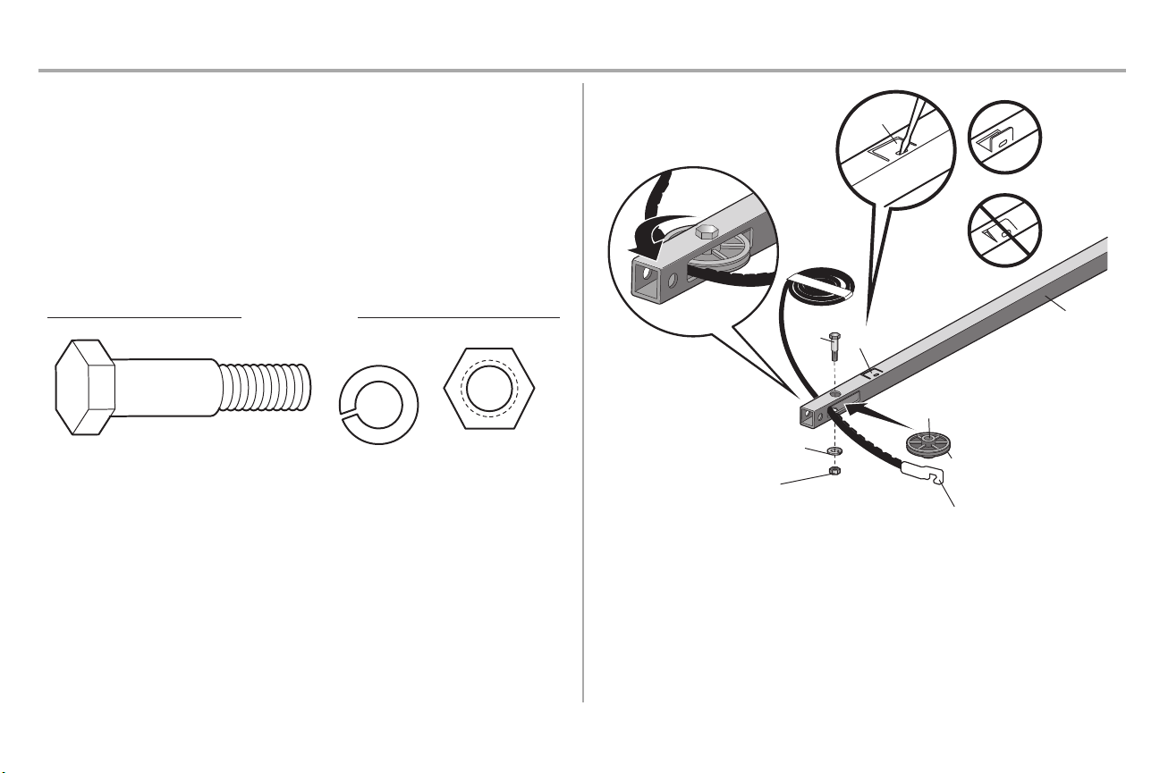
STEP 13 Install the Protector System
®
Be sure power is NOT connected to the garage door opener BEFORE installing the safety reversing
sensor.
To prevent SERIOUS INJURY or DEATH fromclosing garage door:
l Correctlyconnectand align the safetyreversing sensor. Thisrequired safetydevice MUSTNOT
be disabled.
l Install the safetyreversing sensor so beam is NO HIGHER than 6" (15 cm) above garage floor.
IMPORTANTINFORMATION ABOUT THE SAFETY REVERSING SENSORS
The safety reversingsensors must be connected and aligned correctly before the garage door
openerwillmove in the down direction.
The sending sensor (with an amber LED) transmitsan invisible light beam to the receiving sensor (with a
green LED).If an obstruction breaks the light beam while the door is closing, the door will stop and
reverse to the full open position, and the garage door opener lightswill flash 10 times.
NOTE: For energy efficiencythe garage door opener will enter sleep mode when the door is fully
closed. The sleep mode shuts the garage door opener down until activated.The sleep mode is
sequenced with the garage door opener light bulb; as the light bulb turns off the sensor LEDs will turn off
and whenever the garage door opener lights turn on the sensor LEDs will light.The garage door opener
will not go into the sleep mode until the garage door opener has completed 5 cycles upon power up.
When installing the safetyreversing sensorscheck the following:
l Sensors are installed inside the garage, one on either side of the door.
l Sensors are facing each other with the lenses aligned and the receiving sensor lens does not
receive directsunlight.
l Sensors are no more than 6 inches(15 cm) above the floor and the light beam is unobstructed.
The safety reversing sensorscan be attached to the door track,the wall,or the floor. The sensors should
be no more than 6 inches(15 cm) above the floor. If the door trackwill not support the sensor bracketa
wall installation is recommended. Choose one of the following installations.
OPTION A DOOR TRACK INSTALLATION
1. Slide the curved arms of the sensor bracketaround the edge ofthe door track.Snap into place
so that the sensor bracketis flush against the track.
2. Slide the carriage bolt into the slot on each sensor.
3. Insert the bolt through the hole in the sensor bracketand attachwith the wing nut.The lenses on
both sensorsshould point toward each other. Make sure the lens is not obstructed by the sensor
bracket.
22
Page 24

Installation
(Not provided)
No more than
6 inches (15 cm)
1
2
Inside
G
arage
Wall
(Not provided)
Lens
Carriage Bolt
1/4"-20x1/2"
Wing Nut
1/4"-20
3
4
I
nsid
e
G
arage
Wa
l
l
(Not provided)
1 2
Carriage Bolt
1/4"-20x1/2"
Wing Nut
1/4"-20
3
4
STEP 13 Install the Protector System®(continued)
OPTION B WALL INSTALLATION
Ifadditional clearance is needed an extension bracket(not provided) or wood blocks can be used. Make
sure each brackethas the same amount of clearance so they will align correctly.
1. Position the sensor bracket against the wall with the curved armsfacing the door. Make sure
there is enough clearance for the beam to be unobstructed.Mark holes.
2. Drill 3/16 inch pilot holes for each sensor bracketand attach the sensor bracketsto the wall using
lag screws(not provided).
3. Slide the carriage bolt into the slot on each sensor.
4. Insert the bolt through the hole in the sensor bracketand attachwith the wing nut.The lenses on
both sensorsshould point toward each other. Make sure the lens is not obstructed by the sensor
bracket.
OPTION C FLOOR INSTALLATION
Usean extensionbracket(not provided) or wood block to raise the sensor bracketif needed.
1. Carefullymeasure the position of both sensor bracketsso they will be the same distancefrom the
wall and unobstructed.
2. Attach the sensor bracketsto the floor using concrete anchors (not provided).
3. Slide the carriage bolt into the slot on each sensor.
4. Insert the bolt through the hole in the sensor bracketand attachwith the wing nut.The lenses on
both sensorsshould point toward each other. Make sure the lens is not obstructed by the sensor
bracket.
23
Page 25

Installation
HARDWARE
Insulated
Staple
(Not Shown)
Staple
7/16" (11 mm)
WHITE
WHITE
GREY
RED
1
2
3
STEP 14 Wire the Safety Reversing Sensors
Ifyour garage already has wires installed for the safetyreversing sensors,proceed to page 25.
OPTION A INSTALLATION WITHOUT PRE-WIRING
1. Run the wire from both sensors to the garage door opener. Attach the wire to the wall and ceiling
withthe staples.
2. Strip 7/16 inch (11 mm) of insulation fromeach set of wires. Separate the wires. Twistthe white
wires together. Twistthe white/blackwires together.
3. Insert the white wires into the white terminal on the garage door opener. Insertthe white/black
wires into the grey terminal on the garage door opener. To insert or remove the wires from the
terminal,push in the tab witha screwdriver tip.
24
Page 26

Installation
Safety reversing
sensor wires
Pre-installed
wires
White
White/Black
Yellow (for example)
Purple (for example)
Not Provided
Pre-installed wires
Safety reversing
sensor wires
7/16" (11 mm)
Yellow
Purple
1
3
4
7/16"
(11 mm)
2
WHITE
WHITE
RED
GREY
Purple
(for
example)
Yellow
(for example)
To insert or remove the wires from
the terminal, push in the tab with a
screwdriver tip.
5
STEP 14 Wire the Safety Reversing Sensors (continued)
OPTION B PRE-WIRED INSTALLATION
1. Cutthe end of the safetyreversing sensor wire, making sure there is enough wire to reach the
pre-installed wires from the wall.
2. Separate the safetyreversing sensor wires and strip 7/16 inch (11 mm) of insulation fromeach
end. Choose twoof the pre-installed wires and strip 7/16 inch (11 mm) of insulation from each
end. Make sure that you choose the same color pre-installed wires for each sensor.
3. Connectthe pre-installed wires to the sensor wires with wire nuts making sure the colors
correspond for each sensor. For example, the white wire would connect to the yellow wire and
the white/black wire would connect to the purple wire.
4. Atthe garage door opener, strip 7/16 inch (11 mm) of insulation fromeach end of the wires
previously chosen for the safetyreversing sensors.Twistthe like-colored wires together.
5. Insert the wires connected to the white safetysensor wires to the white terminal on the garage
door opener. Insertthe wires that are connectedto the white/blacksafety sensor wires to the grey
terminal on the garage door opener.
25
Page 27

Installation
Ground Tab
Green
Ground
Screw
Ground
Wire
White Wire
Black
Wire
Black
Wire
STEP 15 Connect power
To prevent possible SERIOUS INJURY or DEATH from electrocution or fire:
l Be sure power is NOT connected to the opener, and disconnect power to circuit BEFORE
removing cover to establish permanent wiring connection.
l Garage door installation and wiring MUSTbe incompliance with ALL local electrical and
building codes.
l NEVER use an extension cord, 2-wire adapter, or change plug in ANY way to make it fit outlet.Be
sure the opener is grounded.
To avoid installation difficulties, do not run the openerat this time.
To reduce the risk of electric shock, your garage door opener has a grounding type plug with a third
grounding pin. This plug will only fit into a grounding type outlet.Ifthe plug doesn’t fit into the outlet you
have, contacta qualified electrician to install the proper outlet.
THERE ARE TWO OPTIONS FOR CONNECTING POWER:
OPTION A TYPICAL WIRING
1. Plug in the garage door opener into a grounded outlet.
2. DO NOT run garage door opener at thistime.
OPTION B PERMANENT WIRING
If permanent wiring is requiredby yourlocal code, refer to the following procedure. To make a
permanent connection throughthe 7/8 inch hole in the top of the motor unit (accordingto local
code):
1. Remove the motor unit coverscrewsand set the cover aside.
2. Remove the attached 3-prong cord.
3. Connectthe black (line) wire to the screwon the brassterminal; the white(neutral) wire to the
screwon the silver terminal; and the ground wire to the green ground screw.The opener must
be grounded.
4. Reinstall the cover.
26
Page 28

Installation
Green LED
Amber LED
If the receiving sensor is in direct sunlight,
switch it with sending sensor so it is on the
opposite side of the door.
(invisible light beam)
SENDING SENSOR RECEIVING SENSOR
RED
WHITE
WHITE
GREY
3
2
1
1
2
STEP 16 Aligning the safety reversing sensors
The doorwillnot close if the sensors have not been installed and aligned correctly.
When the light beam is obstructed or misaligned while the door is closing, the door will reverse and the
garage door opener lights will flashten times.Ifthe door isalready open, it will not close.
1. Checkto make sure the LEDs in both sensors are glowing steadily. The LEDsin both sensorswill
glow steadilyif they are aligned and wired correctly.
The sensorscan be aligned by loosening the wing nuts,aligning the sensors,and tightening the wing
nuts.
IFTHE AMBER LED ON THE SENDING SENSOR IS NOT GLOWING:
1. Makesure there is power to the garage door opener.
2. Makesure the sensor wire is not shorted/broken.
3. Makesure the sensor has been wired correctly:white wires to white terminal and white/black
wires to grey terminal.
IFTHE GREEN LED ON THE RECEIVING SENSOR IS NOT GLOWING:
1. Makesure the sensor wire is not shorted/broken.
2. Makesure the sensors are aligned.
STEP 17 Ensure the door control is wired correctly
Ifthe door control has been installed and wired correctly,the command LED on the Motion-Detecting
Control Panel will blink.
27
Page 29

Adjustments
UP (Open)
DOWN (Close)
CORRECT
INCORRECT
UP Button
Adjustment Button
DOWN Button
PROGRAMMING BUTTONS
Introduction
Withouta properly installed safetyreversal system,persons (particularly small children) could be
SERIOUSLY INJUREDor KILLED by a closing garage door.
l Incorrectadjustmentof garage door travel limits will interfere with proper operation of safety
reversal system.
l AfterANY adjustments are made, the safety reversal systemMUSTbe tested.Door MUST reverse
on contactwith 1-1/2" (3.8 cm)high object(or 2x4 laid flat) on floor.
To prevent damage to vehicles,be sure fully open door provides adequate clearance.
Your garage door opener isdesigned with electronic controls to make setup and adjustmentseasy.The
adjustmentsallow you to program where the door will stop in the open (UP) and close (DOWN)position.
The electronic controls sense the amount of force required to open and close the door. The force is
adjusted automatically when you program the travel.
NOTE: If anything interferes with the door’s upward travel it will stop. If anything interferes with the door’s
downward travel, it will reverse.
One-Piece Doors Only
When settingthe UP travel for a one-piece door ensure that the door does not slant backwardswhen
fullyopen (UP). Ifthe door is slanted backwardsthis will cause unnecessarybucking and/or jerking when
the door is opening or closing.
Programming Buttons
The programming buttons are located on the left side panel of the garage door opener and are used to
program the travel. While programming, the UP and DOWN buttonscan be used to move the door as
needed.
To watch a short instructional video on how to program the travel on your
new garage door opener use your smartphone to read the QR Code:
28
Page 30

Adjustments
UP Button
Adjustment Button
DOWN Button
PROGRAMMING BUTTONS
1 2
3
4 5
6 7
STEP 1 Program the Travel
Withouta properly installed safetyreversal system,persons (particularly small children) could be
SERIOUSLY INJUREDor KILLED by a closing garage door.
l Incorrectadjustmentof garage door travel limits will interfere with proper operation of safety
reversal system.
l AfterANY adjustments are made, the safety reversal systemMUSTbe tested.Door MUST reverse
on contactwith 1-1/2" (3.8 cm)high object(or 2x4 laid flat) on floor.
While programming,the UP and DOWN buttonscan be used to move the door as needed.
1. Pressand hold the Adjustment Button until the UP Buttonbegins to flash and/or a beep is heard.
2. Pressand hold the UP Button until the door is in the desired UP position.
3. Once the door is in the desired UP position press and release the AdjustmentButton. The
garage door opener lights will flashtwice and the DOWNButtonwill begin to flash.IMPORTANT
NOTE: For one-piece door installations refer to page 28.
4. Pressand hold the DOWN button until the door is in the desired DOWN position.
5. Once the door is in the desired DOWN position press and release the Adjustment Button.The
garage door opener lights will flashtwice and the UP Button will begin to flash.
6. Pressand release the UP Button.When the door travels to the programmed UP position,the
DOWNButton will begin to flash.
7. Pressand release the DOWN Button.The door will travel to the programmed DOWN position.
Programming is complete.
* If the garage door opener lights are flashing 5 times during the stepsfor Program the Travel,the
programming has timed out. If the garage door opener lights are flashing 10 times during the steps for
Program the Travel, the safetyreversing sensors are misaligned or obstructed(refer to page 27).When
the sensorsare aligned and unobstructed,cyclethe door through a complete up and down cycle using
the remote control or the UP and DOWNbuttons.Programming is complete.Ifyou are unable to operate
the door up and down, repeat the stepsfor Programming the Travel.
29
Page 31

Adjustments
1 2
1
2
STEP 2 Test the Safety Reversal System
STEP 3 Test the Protector System
®
Withouta properly installed safetyreversal system,persons (particularly small children) could be
SERIOUSLY INJUREDor KILLED by a closing garage door.
l Safetyreversal system MUST be testedevery month.
l AfterANY adjustments are made, the safety reversal systemMUSTbe tested.Door MUST reverse
on contactwith 1-1/2" (3.8 cm)high object(or 2x4 laid flat) on the floor.
1. With the door fully open, place a 1-1/2 inch (3.8 cm)board (or a 2x4 laid flat) on the floor,
centered under the garage door.
2. Operate the door in the down direction.The door MUSTreverse on striking the obstruction.
Ifthe door stops and does not reverse on the obstruction,the down travel needs to be increased (refer to
AdjustmentStep 1). Repeat the test.When the door reverses on the 1-1/2" (3.8 cm) board (or 2x4 laid
flat),remove the obstruction and run the opener through 3 or4 complete travel cycles to testadjustment.
Ifthe garage door opener continues to fail the safety reversal test,call a trained door systemstechnician.
Withouta properly installed safetyreversing sensor,persons (particularly small children) could be
SERIOUSLY INJUREDor KILLED by a closing garage door.
1. Open the door. Place the garage door opener carton in the path of the door.
2. Pressthe remote control push button to close the door. The door will not move more than an inch
(2.5 cm),and the garage door opener lightswill flash 10 times.
The garage door opener will not close from a remote control if the LED in either safetyreversing sensor
is off(alerting you to the factthat the sensor is misaligned or obstructed). If the garage door opener
closesthe door when the safetyreversing sensor is obstructed (and the sensors are no more than 6
inches [15 cm] above the floor), call for a trained door systemstechnician.
30
Page 32

Operation
IMPORTANT SAFETY INSTRUCTIONS
To reduce the risk of SEVERE INJURY or DEATH:
1. READAND FOLLOW ALL WARNINGS AND INSTRUCTIONS.
2. ALWAYS keep remote controls out of reach of children. NEVER permit children to operate
or play with garage door control push buttons or remote controls.
3. ONLY activate garage door when it can be seen clearly, it is properly adjusted,and there
are no obstructions to door travel.
4. ALWAYS keep garage door in sight and away frompeople and objects until completely
closed.NO ONE SHOULD CROSS THEPATH OF THE MOVING DOOR.
5. NO ONE SHOULDGO UNDERA STOPPED,PARTIALLY OPENED DOOR.
6. Ifpossible,use emergencyrelease handle to disengage trolley ONLY when garage door is
CLOSED. Use caution when using this release with the door open. Weak or broken
springs or unbalanced door could resultin an open door falling rapidly and/or unexpectedly
and increasing the risk of SEVERE INJURY or DEATH.
7. NEVER use emergencyrelease handle unless garage doorway is clear of persons and
obstructions.
8. NEVER use handle to pull garage door open or closed. If rope knot becomesuntied, you
could fall.
9. After ANY adjustmentsare made, the safetyreversal systemMUST be tested.
10. Safetyreversal system MUST be tested every month. Garage door MUST reverse on contact with
1-1/2" (3.8 cm)high object(or a 2x4 laid flat) on the floor. Failure to adjust the garage door
opener properly increases the riskof SEVERE INJURY or DEATH.
11. ALWAYS KEEP GARAGE DOOR PROPERLY BALANCED(see page 1). An improperly
balanced door may NOT reverse when required and could result in SEVERE INJURYor
DEATH.
12. ALL repairs to cables,spring assemblies and other hardware, ALL of which are under
EXTREME tension, MUSTbe made bya trained door systemstechnician.
13. ALWAYS disconnectelectricpower to garage door opener BEFORE making ANY repairs or
removing covers.
14. This operator system is equipped with an unattended operation feature. The door could move
unexpectedly.NO ONE SHOULD CROSS THE PATH OF THEMOVING DOOR.
15. DO NOT installon aone-piece door if using devices or features providing unattended close.
Unattended devicesand features are to be used ONLY with sectional doors.
16. SAVE THESE INSTRUCTIONS.
31
Page 33

Operation
Features
Your garage door opener isequipped with features to provide you with greater control over your garage
door operation.
®
MyQ
MyQ®technology usesa 900MHzsignal to provide two-way communication between the garage door
opener and MyQ®enabled accessories. Your garage door opener is compatible with up to 8 MyQ
accessories.For Smartphone App control of your garage door opener and other MyQ®accessories,
Chamberlain's MyQ®InternetGateway (model CIGBU) is required.
Alert2Close
The Alert2Close feature provides a visual and an audible alert thatan unattended door is closing.
TIMER-TO-CLOSE (TTC)
The Timer-to-Close feature automaticallyclosesthe garage door aftera specified time period. DO NOT
enable TTC if operating a one-piece door.TTCis to be used ONLY with sectionaldoors.Factory
default is set to off.The garage door opener will beep and the lights will flash before closing the door.
The TTCfeature will deactivate if the garage door encounters an obstruction twice;or the safetyreversing
sensorsare incorrectlyinstalled. The garage door will reverse open and WILL NOTclose until the
obstructions are clear or the safetyreversing sensors are correctlyinstalled. When the obstruction has
been cleared orthe safetyreversing sensors have been aligned, the door will close when the garage
door opener is activated. TTCWILL NOT work if the garage door opener is operating by batterypower or
if the safetyreversing sensors are misaligned. This feature is NOT intended to be the primary method of
closing the door. A keyless entry should be installed in the event of an accidentallock out when
using this feature.
REMOTE CONTROLS AND DOOR CONTROLS (MyQ®)
Your garage door opener hasalready been programmed at the factoryto operate with your remote
control,which changes witheach use, randomly accessing over 100 billion new codes.Compatible with
MyQ®enabled accessories, see page 40.
NOTE: Older Chamberlain remote controls,door controls, and third party products are notcompatible.
MyQ®Accessories MEMORY CAPACITY
RemoteControls Up to 8
®
THE PROTECTOR SYSTEM®(SAFETY REVERSING SENSORS)
When properly connectedand aligned, the safetyreversing sensors will detectan obstruction in the path
of the infrared beam. Ifan obstruction breaks the infrared beamwhile the door is closing,the door will
stopand reverse to full open position, and the opener lights will flash10 times.If the door is fully open,
and the safetyreversing sensors are not installed, or are misaligned, the door will not close from a
remote control. However,you can close the door if you hold the button on the door control or keyless
entry until the door is fullyclosed. The safety reversing sensorsdo not effectthe opening cycle.
ENERGY CONSERVATION
For energy efficiencythe garage door opener will enter sleep mode when the door is fullyclosed. The
sleep mode shutsthe garage door opener down until activated. The sleep mode is sequenced with the
garage door opener light bulb; as the light bulb turns off the sensor LEDs will turn offand whenever the
garage door opener lights turn on the sensor LEDs will light.The garage door opener will not go intothe
sleep mode until the garage door opener has completed 5 cyclesupon power up.
LIGHTS
The garage door opener light bulbs will turn on when the opener is initially plugged in; power is restored
afterinterruption,or when the garage door opener is activated.The lights will turn off automatically after
4-1/2 minutes.An incandescentA19 light bulb (100 wattmaximum) or for maximumenergy efficiencya
26W (100W equivalent) compact fluorescentlight (CFL) bulb may be used. NOTE: Do not use halogen,
short neck,or specialtylight bulbs as these may overheat the end panel or light socket. Do not use LED
bulbs as they may reduce the range or performance of your remote controls.
NOTE: Do not use halogen, short neck,or specialty light bulbs as these may overheat the end panel or
light socket. Do not use LED bulbs as they may reduce the range or performance of your remote controls.
Light Feature
The garage door opener is equipped with an added feature; the lightswill turn on when someone enters
through the open garage door and the safetyreversing sensor infrared beam is broken. For added
control over the light bulbs on your garage door opener, see page 33.
Door Controls Up to 2 MyQ®door controls
KeylessEntries Up to 1
32
Page 34

Operation
ON (TTC)
OFF (TTC)
Command LED
Motion Sensor
Switch
LIGHT
Button
HOLD OPEN
Button(TTC)
Motion
Sensor
Push Bar
1, 5, and
10 Minute
TTC LED
LEARN Button
LOCK Button
Using your Garage Door Opener
The garage door opener can be activated through a wall-mounted door control,remote control, wireless
keylessentryor MyQ®accessory.
When the door is closed and the garage door opener is activated the door will open. If the door senses
an obstruction or isinterrupted while opening the door will stop. When the door is in any position other
than closed and the garage door opener is activatedthe door will close.If the garage door opener
sensesan obstruction while closing, the door will reverse. If the obstruction interrupts the sensor beam
the garage door opener lights will blink 10 times.However,you can close the door if you hold the button
on the door control or keyless entryuntil the door isfully closed. The safety reversing sensorsdo not
affect the opening cycle.
The safety reversing sensor must be connected and aligned correctlybefore the garage door opener will
move in the down direction.
Using the Motion Detecting Control Panel
SYNCHRONIZE THE DOOR CONTROL
To synchronize the door control to the garage door opener, press the push bar until the garage door
opener activates(it may take up to 3 presses).Test the door control by pressing the push bar, each press
of the push bar will activate the garage door opener.
MOTION DETECTING CONTROL PANEL FEATURES
PUSH BAR
Press the push bar to open or close the door.
LIGHTS
Light Button
Press the LIGHT button to turn the garage door opener lightson or off.When the lights are turned on
theywill stayon until the LIGHTbutton is pressed again, or until the garage door opener is activated.
Once the garage door opener is activated the lights will turn offafter the specified period oftime (the
factory setting is 4-1/2 minutes).The LIGHTbutton will not control the lightswhen the door is in motion.
To change the amount of time the garage dooropenerlights willstay on:
Press and hold the LOCK button (approximately 10 seconds) until the garage door opener lights flash.
The timeinterval is indicated by the number timesthe garage door opener flashes:
l 1 flash is 1-1/2 minutes
l 2 flashesis 2-1/2 minutes
l 3 flashesis 3-1/2 minutes
l 4 flashesis 4-1/2 minutes
To cycle through the time intervalsrepeat the step above.
Light Feature
The lights will turn on when someone enters through the open garage door and the safetyreversing
sensor infrared beam is broken.
l Deactivate: Press and hold the LIGHTbutton (approximately 10 seconds) until the garage door
opener lightsturn on, then off again.
l Activate: Start with the garage door opener lightson. Press and hold the LIGHTbutton
(approximately 10 seconds) until the garage door opener lights turn off,then on again.
Ifthe command LED is continuously blinking, the LOCK feature needs to be deactivated.
33
Page 35

Operation
ON (TTC)
OFF (TTC)
Command LED
Motion Sensor
Switch
LIGHT
Button
HOLD OPEN
Button(TTC)
Motion
Sensor
Push Bar
1, 5, and
10 Minute
TTC LED
LEARN Button
LOCK Button
The command LED
will flash once.
The command LED will
flash once again.
1
2
OR
PIN
? ? ? ?
3
Motion Detecting Control Panel (continued)
LOCK
The LOCK feature is designed to prevent activation of the garage door opener from remote controls
while stillallowing activation from the door control and keyless entry.This feature is useful for added
peace of mind when the home is empty(i.e. vacation).
l Activate: Press and hold the LOCK button for 2 seconds.The command LED will flashas long
as the lockfeature is activated and your handheld remote control will not operate your door at
thistime.
l Deactivate: Press and hold the LOCK button again for 2 seconds. The command LED will stop
flashing and normal operation will resume.
TIMER-TO-CLOSE
DO NOT enable TTCif operatinga one-piece door.The TTC can be turned on oroff and the time
interval can be adjusted to 1, 5, and 10 minute intervals.Once the TTC has been set and the door is
open, the selectedclose interval will blink and begin to count down to close the door.
l Activate: Press and hold the ON button until one of the TTCLEDs light up. Then pressthe ON
button again to cyclethrough the time interval options (the corresponding TTC LED will light for
each time interval). The garage door opener light bulbs will blink as confirmation.
l Deactivate: Press and hold the OFF buttonuntil all TTC LEDs turn off and a beep is heard from
the motor unit.
l Temporarily hold door open (suspend TTC): Press and release the HOLD OPEN button. Press
the HOLD OPEN button again to resume normal TTCoperation.
PROGRAM
Any compatible remote controls, wirelesskeylessentry,or MyQ®accessories can be programmed to the
garage door opener by pressing the Learn button.
Remote Control
Yourremote control has been programmed at the factory to operate with yourgarage dooropener.
Older Chamberlain remote controlsare NOT compatible,see page 40 for compatible accessories.
Programming can be done through the door control or the learn button the garage door opener. To
program additional accessories refer to the instructions provided with the accessory or visit
www.chamberlain.com. If your vehicle is equipped with a Homelink®, you may require an external
adapter depending on the make,model, and year of your vehicle. Visit www.homelink.comfor additional
information.
TO ADD, REPROGRAM, OR CHANGE A REMOTE CONTROL/KEYLESS ENTRY PIN
USING THE MOTION-DETECTING CONTROL PANEL
1. Pressthe LEARN button on the door control to enter Programming Mode.
2. Pressthe LEARN button again, the LED will flash once.
3. Remote Control:
Press the buttonon the remote control that you wishto operate your garage door. Keyless
Entry:
Enter a 4-digit personal identification number (PIN) of your choice on the keylessentry keypad.
Then press the ENTERbutton.
The garage door opener lights will flash(or two clickswill be heard) when the code has been
programmed. Repeat the steps for programming additional remote controlsor keyless entrydevices.
34
Page 36

Operation
LEARN LED
LEARN
Button
“click”
“click”
1
3
2
Remote Control (continued)
PROGRAM A REMOTE CONTROL USING THE LEARN BUTTON
1. Locatethe Learn Button.
2. Pressand immediatelyrelease the Learn button. The Learn LED will glow steady for 30 seconds.
Within 30 seconds...
3. Pressand hold the button on the remote control thatyou wish to use.Release the button when
the garage door opener lights blink or two clicksare heard.When replacing the light lens cover,
ensure the antenna wires are hanging straight down.
To Erase the Memory
ERASE ALL REMOTE CONTROLS AND KEYLESS ENTRIES
1. Pressand hold the LEARN button on garage door opener until the learn LED goes out
(approximately 6 seconds).All remote control and keylessentry codes are nowerased.
Reprogram any accessory you wishto use.
ERASE ALL DEVICES (Including MyQ®enabled accessories)
1. Pressand hold the LEARN button on garage door opener until the learn LED goes out
(approximately 6 seconds).
2. Immediately pressand hold the LEARN buttonagain until the learn LED goes out.All codes are
now erased. Reprogram any accessory you wish to use.
35
Page 37

Operation
To Open the Door Manually
To prevent possible SERIOUS INJURY or DEATH from a falling garage door:
l Ifpossible, use emergency release handle to disengage trolley ONLY when garage door is
CLOSED. Weak or broken springs or unbalanced door could result in anopen door falling
rapidly and/or unexpectedly.
l NEVER use emergency release handle unlessgarage doorwayis clear of persons and
obstructions.
l NEVER use handle to pull door open or closed. Ifrope knot becomesuntied, you could fall.
DISCONNECT THE TROLLEY
1. The door should be fully closed if possible.
2. Pull down on the emergencyrelease handle so the trolley release arm snaps to the vertical
position.The door can now be raised and lowered as often as necessary.
TO RECONNECT THE TROLLEY
1. Pull the emergency release handle toward the garage door opener so the trolley release arm
snaps to the horizontal position. The trolley will reconnecton the nextUP or DOWN operation,
either manually or by using the door control or remote control.
36
Page 38

Maintenance
1
2
3
Maintenance Schedule
EVERY MONTH
l Manually operate door. If itis unbalanced or binding, call a trained door systemstechnician.
l Checkto be sure door opensand closes fully. Adjust if necessary,see page28.
l Testthe safety reversal system. Adjust if necessary,see page30.
EVERY YEAR
l Oil door rollers,bearings and hinges. The garage door opener does not require additional
lubrication. Do not grease the door tracks.
The Remote Control Battery
To prevent possible SERIOUS INJURY or DEATH:
l NEVER allow small children near batteries.
l Ifbatteryis swallowed, immediately notifydoctor.
To reduce risk of fire, explosion or chemical burn:
l Replace ONLY with 3V CR2032 coin batteries.
l DO NOTrecharge, disassemble, heat above 212°F (100°C) or incinerate.
The 3V CR2032 lithium batteryshould produce power for up to
3 years.If the battery is low, the remote control’sLED will not
flash when the buttonis pressed.
To replace battery,pry open the case firstin the middle (1),
then at each side (2 and 3) with the visor clip. Replace the
batterieswith only 3V CR2032 coin cell batteries.Insert battery
positiveside up. Dispose of old batteries properly.
NOTICE: To complywith FCC and /or In dustryCanada (IC)rules,adjustment or modificationsof thistransceiverare proh ibited. THERE
ARENO USERSERVICEABLEPARTS.Any changes ormodificationsnot expresslyapp roved bythe party responsiblefor compliance
could void the user'sauthorityto operate the equipment.
Thisdevicecomplieswith Part 15 of the FCC rules and IC RSS-210. Operation issubject to the followingtwo conditions: (1)thisdevice
maynot cause harmfulinterference, and (2) th isdevicemust accept anyinterference received, includinginterference that maycause
undesired operation.
ThisClass Bdigitala pparatu scomplies with Canadian ICES-003.
AVIS: Lesrèglesde laFCC et/ou d’Indu strieCanada (IC) interdisent tout ajustement ou toute modificationde ce récepteur. IL N’EXISTE
AUCUNE PIÈCESUSCEPTIBLED’ÊTREENTRETENUEPARL’UTILISATEUR. Tout changement o u toute modification no n
expressément a pprouvé p ar la pa rtie respon sable de la conformitépeu t avoirpour résultat d'ann uler l'autoritéd e l'utilisateu rde faire
fonctionner l'équipement.
Cet a ppareilestconformeaux dispositions de lapartie 15 du règlement de la FCC e t de l'norme IC RSS-210. Son utilisation estassujettie
aux de ux conditoinssuivantes: (1) ce dispositifne peu t causerdes interférencesnuisibles,et (2)ce dispositifd oit accepter toute
interférence recue, y comprisune interférencepouvant causer un fonctionnement non sou haité.
Cet a ppareilnumerique d e la classeBestconformea la normeNMB-003 du Canada.
37
Page 39

Troubleshooting
Diagnostic Chart
Your garage door opener isprogrammed with self-diagnosticcapabilities. The UP and DOWN arrows on the garage door opener flash the diagnostic codes.
DIAGNOSTICCODE SYMPTOM SOLUTION
Up Arrow
Flash(es)
1 1
1 2
1 3
1 4
1 5
1 6
2 1-5
3 2
Down Arrow
Flash(es)
The garage door opener will not close and the light bulbs flash. Safetysensors are not installed, connected,or wires may be cut.Inspectsensor wires for a
disconnectedor cut wire.
The garage door opener will not close and the light bulbs flash. There is a short or reversed wire for the safety sensors. Inspect safetysensor wire at all staple and
connection points,replace wire or correctas needed.
The door control will not function. The wires for the door control are shorted or the door control is faulty.Inspectdoor control wires at all
staple and connection points,replace wire orcorrect as needed.
The garage door opener will not close and the light bulbs flash. Safetysensors are misaligned or were momentarily obstructed.Realign both sensors to ensure both
LEDs are steadyand notflickering.Make sure nothing is hanging or mounted on the door that would
interrupt the sensor’spath while closing.
Door moves6-8" stops or reverses. Manually open and close the door. Checkfor binding or obstructions,such as a broken spring or door
lock,correctas needed. Check wiring connections at travel module and atthe logic board. Replace
travel module ifnecessary.
No movement, only a single click. Manually open and close the door. Checkfor binding orobstructions,such as a broken spring or door
lock,correctas needed. Replace logic board if necessary.
Opener hums for 1-2 seconds no movement. Manually open and close the door. Checkfor binding or obstructions,such as a broken spring or door
lock,correctas needed. Replace motor if necessary.
Door coastsafterit has come to a complete stop. Program travel to coasting position or havedoor balanced by a trained door systemstechnician.
No movement, or sound. Replace logic board.
Unable to setthe travel or retain position. Checktravel module for proper assembly,replace if necessary.
38
Page 40

Troubleshooting
DIAGNOSTICCODE SYMPTOM SOLUTION
Up Arrow
Flash(es)
4 1-4
4 5
4 6
Down Arrow
Flash(es)
Door is moving stops or reverses.
Opener runs approximately 6-8", stops and reverses. Communication error to travel module. Check travel module connections,replace travel module if
The garage door opener will not close and the light bulbs
flash.
Manually open and close the door. Checkfor binding or obstructions,such as a broken spring or door lock,
correctas needed. If the door is binding or sticking contacta trained door systemstechnician. If door is not
binding or sticking attemptto reprogram travel (refer to page 28).
necessary.
Safetysensors are misaligned or were momentarily obstructed. Realign bothsensors to ensure both LEDs
are steady and not flickering.Make sure nothing is hanging or mounted on the door that would interrupt the
sensor’spath while closing.
The garage door opener can beep for several reasons:
l Garage door opener has been activated through a device or feature such as Timer-to- Close or
garage door monitor, see page 32.
My remote control will not activate the garage door:
l Verify the lock feature is not activated on the door control.
l Reprogram the remote control.
l Ifthe remote control will still not activate the door check the diagnosticcodes to ensure the garage
door opener is working properly.
My door will not close and the light bulbs blink on my motor unit:
The safety reversing sensor must be connected and aligned correctlybefore the garage door opener
will move in the down direction.
l Verify the safetysensors are properly installed,aligned and free of any obstructions.
My garage dooropener light(s) willnot turnoff when the door is open:
The garage door opener is equipped with a feature that turns the light on when the safetyreversing
sensorshave been obstructedor when the motion sensor on the door control detectsmovement in the
garage. These features can be disabled using the door control, see page 33.
My neighbor’sremote control opens my garage door:
Erase the memoryfrom your garage door opener and reprogram the remote control(s).
The LEDs on the doorcontrol blink:
Ifyou have a Smart Control Panel installed and the TTCis setto a customtime,press the ON button on
the Premium Motion-Detecting Control Panel to set the time properly.
My vehicle's Homelink®is not programmingto my garage door opener:
Depending on the make,model, and year ofyour vehicle an external adapter may be required. Visit
www.homelink.com for additional information.
39
Page 41

Accessories
CLOSED
7702CB
8808CB
8810CB
CIGBU
Outside Quick Release:
Required for a garage with NO
access door.
8 Foot (2.4 m) Rail Extension:
To allow an 8 foot (2.4 m) door
to open fully.
10 Foot (3 m) Rail Extension:
To allow a 10 foot (3 m) door
to open fully.
®
MyQ
Internet Gateway:
Internet enabled accessory
which connects to the
computer and allows you to
monitor and control garage
door openers and lighting
accessories enabled by MyQ®
technology.
041A5281-1
Extension Brackets:
(Optional) For safety reversing
sensor installation onto the
wall or fl oor.
PILCEV MyQ® Remote Lamp Control:
Control home lighting and
garage doors with one remote.
For use with plug-in lamps.
Synchronize to work with MyQ®
compatible garage door openers
and remote controls.
CLLP1
Laser Parking Assistant:
Park in the right spot every time!
A laser beam is activated by your
garage door opener and
projected on to the dashboard
of your vehicle to guide perfect
parking.
CLSS1
AGDMEV
BIK01
System Surge Protector:
The Garage Door Opener Surge
Protector is designed to protect
Chamberlain garage door
openers against damage from
lightning and power surges. Easy
to install.
Garage Door and Gate Monitor:
Monitor open/closed status for
up to 4 MyQ
®
compatible garage
door openers or gate operators
and close them from anywhere in
the home.
Installation Upgrade Kit:
The Installation Upgrade Kit
includes all components needed
to hang garage door openers up
to 24" (61 cm) from the ceiling.
953EV
956EV
940EV
Remote Control:
Works with ALL Chamberlain
openers from 1993-present.
®
compatible. Includes visor
MyQ
clip.
Keychain Remote Control:
Works with ALL Chamberlain
openers from 1993-present.
®
MyQ
compatible. With key ring.
Wireless Keypad:
For use outside of the home to
enable access to the garage
using a 4-digit PIN. Works with
ALL Chamberlain openers from
1993-present. MyQ
®
compatible.
40
Page 42

Warranty
Contact Information
For installation and service information call:
1-800-528-9131
Before calling, please have the model number of the garage
door opener. If you are calling about a Troubleshooting issue,
it is recommended that you have access to your garage door
opener while calling. If you are ordering a repair part please
have the following information: part number, part name, and
model number.
Address repair parts orders to:
The Chamberlain Group, Inc.
6050 S. Country Club Road
Tucson, AZ 85706
CHAMBERLAIN® LIMITED WARRANTY
®
The Chamberlain Group, Inc.
in which this product is originally installed, that it is free from defects in materials and/or workmanship for a
specifi c period of time as defi ned below (the “Warranty Period”). The warranty period commences from the date
of purchase.
Parts Motor Accessories Belt
5 Years Lifetime 1 year Lifetime
The proper operation of this product is dependent on your compliance with the instructions regarding
installation, operation, and maintenance and testing. Failure to comply strictly with those instructions will void
this limited warranty in its entirety. If, during the limited warranty period, this product appears to contain a defect
covered by this limited warranty, call 1-800- 528-9131, toll free, before dismantling this product. You will be
advised of disassembly and shipping instructions when you call. Then send the product or component, pre-paid
and insured, as directed to our service center for warranty repair. Please include a brief description of the
problem and a dated proof- of-purchase receipt with any product returned for warranty repair. Products returned
to Seller for warranty repair, which upon receipt by Seller are confi rmed to be defective and covered by this
limited warranty, will be repaired or replaced (at Seller’s sole option) at no cost to you and returned pre-paid.
Defective parts will be repaired or replaced with new or factory rebuilt parts at Seller’s sole option. [You are
responsible for any costs incurred in removing and/or reinstalling the product or any component .]
ALL IMPLIED WARRANTIES FOR THE PRODUCT, INCLUDING BUT NOT LIMITED TO ANY IMPLIED
WARRANTIES OF MERCHANTABILITY AND FITNESS FOR A PARTICULAR PURPOSE, ARE LIMITED
IN DURATION TO THE APPLICABLE LIMITED WARRANTY PERIOD SET FORTH ABOVE FOR THE
RELATED COMPONENT(S), AND NO IMPLIED WARRANTIES WILL EXIST OR APPLY AFTER SUCH
PERIOD. Some States and Provinces do not allow limitations on how long an implied warranty
lasts, so the above limitation may not apply to you. THIS LIMITED WARRANTY DOES NOT COVER
NON-DEFECT DAMAGE, DAMAGE CAUSED BY IMPROPER INSTALLATION, OPERATION OR CARE
(INCLUDING, BUT NOT LIMITED TO ABUSE, MISUSE, FAILURE TO PROVIDE REASONABLE AND
NECESSARY MAINTENANCE, UNAUTHORIZED REPAIRS OR ANY ALTERATIONS TO THIS PRODUCT),
LABOR CHARGES FOR REINSTALLING A REPAIRED OR REPLACED UNIT, REPLACEMENT OF
CONSUMABLE ITEMS (E.G., BATTERIES IN REMOTE CONTROL TRANSMITTERS AND LIGHT BULBS),
OR UNITS INSTALLED FOR NON-RESIDENTIAL USE. THIS LIMITED WARRANTY DOES NOT COVER
ANY PROBLEMS WITH, OR RELATING TO, THE GARAGE DOOR OR GARAGE DOOR HARDWARE,
INCLUDING BUT NOT LIMITED TO THE DOOR SPRINGS, DOOR ROLLERS, DOOR ALIGNMENT
OR HINGES. THIS LIMITED WARRANTY ALSO DOES NOT COVER ANY PROBLEMS CAUSED BY
INTERFERENCE. UNDER NO CIRCUMSTANCES SHALL SELLER BE LIABLE FOR CONSEQUENTIAL,
INCIDENTAL OR SPECIAL DAMAGES ARISING IN CONNECTION WITH USE, OR INABILITY TO USE,
THIS PRODUCT. IN NO EVENT SHALL SELLER’S LIABILITY FOR BREACH OF WARRANTY, BREACH
OF CONTRACT, NEGLIGENCE OR STRICT LIABILITY EXCEED THE COST OF THE PRODUCT COVERED
HEREBY. NO PERSON IS AUTHORIZED TO ASSUME FOR US ANY OTHER LIABILITY IN CONNECTION
WITH THE SALE OF THIS PRODUCT.
Some states and provinces do not allow the exclusion or limitation of consequential, incidental or special
damages, so the above limitation or exclusion may not apply to you. This limited warranty gives you specifi c
legal rights, and you may also have other rights, which vary from state to state and province to province.
(“Seller”) warrants to the fi rst retail purchaser of this product, for the residence
WARRANTY PERIOD
41
Page 43

Repair Parts
Rail Assembly Parts
Description Part Number
1 Belt 41A5250
2 Pulley 144C54
3 Master Link 4A1008
4 Rail 41A5665
5 Trolley Assembly 41C5141-2
6 “U” Bracket 12D598-1
Not Shown
Wear Pads 183A163
Hardware Bag 041A7920-2
Accessories
Description Part Number
1 Motion-Detecting Control
Panel
2 Remote Control 953ESTD
41A7327-1
Installation Parts
2
1
Description Part Number
3
1 Curved Door Arm 178B35
2 Door Bracket with Clevis Pin
and Fastener
3 Emergency Release Rope and
3
Handle
4 Header Bracket with Clevis Pin
41A5047-1
41A2828
41A5047-2
NOTICE
11
and Fastener
5 Remote Control
4
5
6
Visor Clip
6 Safety Sensor Bracket 041A5266-3
7 Safety Sensor Kit Receiving
and sending sensors with wire
29B137
41A5034
8 Straight Door Arm 178B34
9 White and Red/White Wire 41B4494-1
10 3V CR2032 Lithium Battery 10A20
11 Hanging Brackets 12B776
8
Not Shown
Owner’s Manual 114A4309
1
2
2
1
4
7
6
9
5
10
42
Page 44

Repair Parts
Garage Door Opener Parts
13
4
5
11
10
12
9
Description Part Number
1 Belt Cap Retainer 41A4371
2 Gear and Sprocket 41A4885-5
1
2
3
4
5
14
6
8
7
3 End Panel with Light Socket 041A7760
4 Light Socket 41C279
5 Light Lens 41D7570
6 Capacitor 30B532
7 Capacitor Bracket 12A373
8 Travel Module 041D7742-7
9 Cover 041A7620-8
10 Receiver Logic Board 45ACT
11 End Panel for Receiver Logic Board
with Light Socket
12 Motor with Travel Module 041A7442
13 Line Cord 41B4245
14 Terminal Block 41A3150
Not Shown
Wire Harness Kit 041A7948
41D7638
© 2013, The Chamberlain Group, Inc.
114A4309I All Rights Reserved
 Loading...