

Page 1
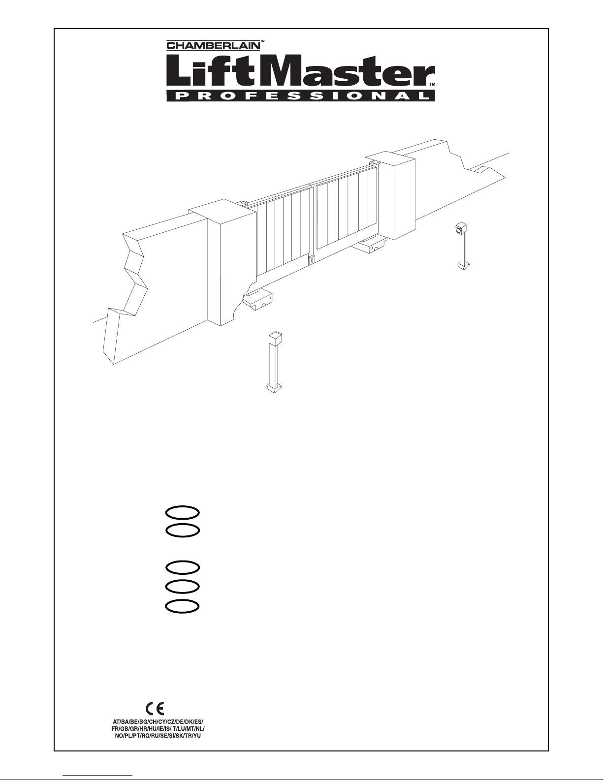
Anleitungen - Unterflurantrieb
Instructions - Automatisme enterré pour
portail à battants
Instructions - Underground gate actuator
Instrukties - Ondergrondse aandrijving
Istruzioni - Apricancello interrato
SUB324M
(24V)
nl
it
de
fr
en
Chamberlain GmbH
Alfred-Nobel-Str. 4
D-66793 Saarwellingen
www.chamberlain.de
Page 2
de-1
BEGINNEN SIE MIT LESEN DIESER WICHTIGEN SICHERHEITSREGELN
Beim Umgang mit Werkzeugen und Kleinteilen
Vorsicht walten lassen und weder Ringe, Uhren
noch lose Kleidungsstücke tragen, wenn Sie
Installations- oder Reparaturarbeiten an einem Tor
vornehmen.
Elektrische Leitungen sind entsprechend den lokalen
Bau- und Elektroinstallationsvorschriften zu verlegen.
Das elektrische Kabel darf nur an ein
ordnungsgemäß geerdetes Netz angeschlossen
werden.
Unterbrechen Sie den Strom zum Torantrieb bevor
Sie Veränderungen daran vornehmen (z.B. bei
Reinigung).
Entfernen Sie bitte alle am Tor angebrachten
Schlösser um Schaden am Tor zu vermeiden.
Es ist wichtig, das Tor immer gut gangbar zu
halten. Tore, die steckenbleiben oder verklemmen,
sind unverzüglich zu reparieren.Versuchen Sie
nicht das Tor selbst zu reparieren. Bestellen Sie
dafür einen Fachmann.
Entfernen Sie Zubehör aus der Nähe von Kindern.
Erlauben Sie Kindern nicht Wandtaster und
Fernbedienungen zu bedienen. Schwere
Verletzungen können durch ein sich schließendes
Tor verursacht werden.
Stellen Sie sicher, daß Personen, die den Antrieb
montieren, warten oder bedienen diesen
Anleitungen folgen.
Bewahren Sie die Anleitung an einem Ort auf, an
dem schnell auf sie zurückgegriffen werden kann.
Solche Warnzeichen bedeuten “Vorsicht!”, eine Aufforderung zur Beachtung, da ihre Missachtung Personenbzw. Sachschäden verursachen kann. Bitte lesen Sie diese Warnungen sorgfältig.
Dieser Antrieb ist so konstruiert und geprüft, daß er bei Installation und Benutzung unter genauer Befolgung der
anschließenden Sicherheitsregeln angemessene Sicherheit bietet.
Die Nichtbeachtung der folgenden Sicherheitsregeln kann ernsthafte Personen- oder Sachschäden
verursachen.
Inhalt:
Sicherheitsregeln: Seite 1
Technische Daten: Seite 1
Garantie: Seite 1
Verpackungsinhalte: Seite 2
Bevor Sie beginnen: Seite 2
Montage des Antriebes: Seite 2, Abbildungen -
Elektrischer Anschluss: Seite 2, Abb.
Sicherheit : Seite 3
Kontrolle: Seite 3
Zum Schluß: Seite 3
Zubehör: Seite 3, Abbildung
11
1
91
TECHNISCHE DATEN
GARANTIE
Chamberlain GmbH garantiert dem ersten Käufer, der das Produkt im Einzelhandel erwirbt (erster
"Einzelhandelskäufer") daß es, ab dem Datum des Erwerbs volle 24 Monate (2 Jahre) lang von jeglichen
Materialschäden bzw. Herstellungsfehlern frei ist. Diese Garantie gilt für den Unterflurantrieb. Bei Empfang
des Produkts obliegt es dem ersten Einzelhandelskäufer, dieses auf sichtbare Schäden zu prüfen.
Bedingungen: Die vorliegende Garantie ist das einzige Rechtsmittel, das dem Käufer gesetzmäßig wegen
Schäden zusteht, die mit einem defekten Teil bzw. Produkt in Verbindung stehen bzw. sich aus einem
solchen ergeben. Die vorliegende Garantie beschränkt sich ausschließlich auf Reparatur bzw. Ersatz der
Teile dieses Produkts, die als schadhaft befunden werden. Die vorliegende Garantie gilt nicht für Schäden,
die nicht auf Defekte sondern auf den unrichtigen Gebrauch zurückzuführen sind (d.h. einschließlich
jedweder Benutzung, die nicht genau den Anleitungen bzw. Anweisungen der Chamberlain GmbH
hinsichtlich Installation, Betrieb und Pflege entspricht, sowie des Versäumnisses, erforderliche
Instandhaltungs- und Justierungsarbeiten rechtzeitig durchzuführen, bzw. der Durchführung von
Adaptierungen oder Veränderungen an diesem Produkt). Sie deckt auch nicht die Arbeitskosten für den
Ausbau bzw. den Wiedereinbau eines reparierten oder ersetzten Geräts oder dessen Ersatzbatterien. Ein
Produkt im Rahmen der Garantie, hinsichtlich dessen entschieden wird, daß es Materialschäden bzw.
Herstellungsfehler aufweist, wird dem Eigentümer ohne Kosten für Reparatur bzw. Ersatzteile nach
Gutdünken der Chamberlain GmbH repariert oder ersetzt. Sollte das Produkt während der Garantiezeit
defekt erscheinen, so wenden Sie sich bitte an die Firma, von der Sie es ursprünglich gekauft haben.
Die Garantie beeinträchtigt nicht die dem Käufer im Rahmen gültiger zutreffender nationaler Gesetze oder
Statuten zustehenden Rechte oder Rechte gegenüber dem Einzelhändler, die sich für den Käufer aus dem
Verkauf/Kaufvertrag ergeben. Bei Nichtbestehen von zutreffenden nationalen bzw. EG-Gesetzen ist diese
Garantie das einzige und exklusive Rechtsmittel, das dem Käufer zur Verfügung steht, und weder
Chamberlain GmbH noch die Filialen oder Händler der Firma sind für irgendwelche Neben- oder
Folgeschäden durch jedwede ausdrückliche oder stillschweigende Garantie bezüglich dieses Produkts haftbar.
Weder Vertreter noch sonstige Personen sind berechtigt, im Namen von Chamberlain GmbH irgendeine
sonstige Verantwortung in Verbindung mit dem Verkauf dieses Produktes zu übernehmen.
Nennspannung
Nennleistung
Nennstrom
Motordrehzahl
Zyklen (Volllast)
Arbeitstemperatur
Schutzklasse
Schutzart
Gewicht (nur Motor)
Steuerung
Handsender
Funkfrequenz
Lichtschranke
Signallampe
Schlüsselschalter
Aussenantenne
Maximale Flügellänge
Max. Flügelgewicht
24V
48
2,0
2500
7min
-25/+75
I
67
10
optional
optional
optional
optional
optional
optional
optional
3,5m
300kg/2,5m
WICHTIGE ANWEISUNGEN FÜR
SICHERE MONTAGE
ACHTUNG - FALSCHE MONTAGE KANN ZU
ERNSTHAFTEN VERLETZUNGEN FÜHREN!
Nach der Installation ist zu überprüfen, dass der
Mechanismus richtig eingestellt ist und dass der
Antrieb das Sicherheitssystem und der Handsender,
falls vorhanden, richtig funktionieren.
Bei Antrieben, die von einem Schalter mit AUS
Voreinstellung gesteuert werden sollen, muss das
Steuerungsbedienteil in direkter Sichtweite vom
angetriebenen Teil, aber entfernt von sich bewegenden
Teilen und mind. in einer Höhe von 1,5m angebracht
werden. Anmerkung: Die Mindesthöhe von 1,5m gilt
nicht für Steuerungsbedienteile mit AUS
Voreinstellung, die durch Schlüssel oder
dergleichen gesteuert werden.
Das angetriebene Teil kann sich unkontrolliert
bewegen, z.B. durch mechanisches Versagen,
wenn der Handsender betrieben wird.
Beim Betreiben einer Steuerung mit AUSVoreinstellung absichern, dass andere Personen
vom Gerät entfernt gehalten werden.
V(DC)
W
A
U/min
ED
°C
IP
kg
Page 3
VERPACKUNGSINHALTE
SUB324M (Motor)
• Motor inkl. Anschlußkabel
SUB300B (Box)
• Box (1x)
• Deckel für Box (1x)
• Blende für Box (1x)
• Schrauben für Deckel (4x)
• Muttern für Motor (4x)
SUB-110 (110º Grad Arm, Standardarm)
• Antriebsarm 110º (1x)
• Motorarm 110º (1x)
• Schraube Motorarm (1x)
• Mutter Motorarm (1x)
• Entriegelungsschlüssel (1x)
• Lagerkugel (1x)
• Endanschlag Box AUF (1x)
• Endanschlag ZU (1x)
• Verbindungsarm
• Schrauben Verbindungsarm (2x)
• Scheiben Verbindungsarm (2x)
SUB-180 (180º Grad Arm)
Öffnet Tore bis zu 180º
SUB-100S (100 Grad Arm mit Schiene)
Wird verwendet, wenn die Box nicht so installiert werden
kann, dass die Drehpunkte untereinander liegen.
BEVOR SIE BEGINNEN
Planung und Präzision ist für die Montage eines
Unterflurantriebs äußerst wichtig, damit die
Funktion später nicht eingeschränkt oder
unmöglich ist.
Es muß eine Entwässerung, Drainage, Ablauf etc.
vorhanden sein, sonst ist eine Fehlfunktion
unvermeidlich.
Torgröße: Die Torgröße ist ein sehr wichtiger Faktor. Wind
kann das Tor bremsen oder es verspannen und den
Kraftbedarf stark erhöhen.
Torgewicht: Die Angabe Torgewicht stellt nur eine
ungefähre Kenngröße dar, die sehr stark vom tatsächlichen
Bedarf abweichen kann. Die Funktion ist wichtig.
Einfluß durch Temperatur: Tiefe Außentemperaturen
können das Anfahren erschweren (Bodenveränderungen
etc.) oder verhindern.
Betriebsfrequenz/Einschaltdauer: Die Antriebe haben
eine maximale Einschaltdauer von ca. 30-50% (z.B. 50%
einer Stunde). Dieser Faktor ist stark abhängig von vielen
Einflussfaktoren. Der Antrieb ist nicht geeignet für Anlagen
mit hoher Zyklenzahl (Dauerbetrieb) und hat das Erlöschen
der Garantie zur Folge.
VORBEREITUNGEN
Überprüfen Sie bitte vor der Montage den Inhalt der Verpackung
auf Vollständigkeit. Bedenken Sie, daß Sie noch Material
benötigen, daß sich verständlicherweise nicht in unserem
Lieferumfang befinden kann (Leerrohr, Kabel, Schrauben, Dübel
etc.). Um störende Pendelbewegungen zu vermeiden,
sollte der Flügel stabil und die Torangeln möglichst spielfrei sein.
Je leichtgängiger der Flügel, desto feinfühliger ist die Kraft
einzustellen. Labile Holztore sollten mit einem Metallrahmen
verstärkt werden.
MONTAGE DES ANTRIEBS -
1. Der Drehpunkt des Tores befindet sich auf der
Montagebox = Drehpunkt des Armes (SUB-110 und
SUB-180) (Abbildungen 5-8).
SUB-110 öffnet Tore bis zu 110º Grad. Montieren Sie
den Arm, der später am Tor angeschweisst wird und
vergessen Sie nicht die Lagerkugel. Details siehe auch
unter Zusammenbau und Einstellung (Abbildungen 2-4).
SUB-180 öffnet Tore bis zu 180º Grad. Eine detaillierte
Beschreibung des Zusammenbaus liegt dem SUB-180
Arm bei.
SUB-100S ist ein spezieller Arm mit Schiene bei dem der
Antrieb nicht genau unter dem Drehpunkt liegen muss.
Das ist ideal für den Nachrüstfall oder speziellen
Pfeilersituationen (max. 300kg/3m). Eine detaillierte
Beschreibung des Zusammenbaus liegt dem SUB-100S
Arm bei.
2. Legen Sie die Maße fest, die Sie benötigen um ein
genügend großes Loch für die Box auszuheben. Wichtig
für die Position der Box ist der Öffnungswinkel des Tores.
Abbildungen 5-7.
Die Box muß einbetoniert werden, achten Sie dabei auf
die Leerrohre für Strom und die Entwässerung
(Abbildung 1). Achtung auf den endgültigen Ausbau der
Anlage (Pflasterung etc.). Die Box sollte minimal höher
liegen als die letzte Schicht.
Der Beton braucht einige Tage bevor er die notwendige
Festigkeit erhält. Sie sollten zumindest Festigkeitsklasse
MG2a nach DIN wählen (normale Festigkeit).
3. Danach kann das Tor darüber positioniert werden.
Zusätzliche Scharniere zur Führung sind in jedem Fall
erforderlich.
4. Der Arm mit der Entriegelung muß am Tor fest verschweißt
werden. Durch Drehen mit dem Spezialschlüssel wird das
Tor entriegelt und kann von Hand geöffnet werden
(Abbildungen 1, 4 und 8).
5. Die Montage von Endanschlägen am Boden für die
Laufbegrenzung des Tores ist unbedingt erforderlich
(Abbildung 9).
6. Nach Abschluß aller Arbeiten ist es von Vorteil die Box mit
Silikon gegen eindringendes Wasser zusätzlich abzusichern.
Tipp:
Wird das Tor gleichzeitig mit dem Antrieb geliefert (keine
Nachrüstung), dann sollte wie folgt vorgegangen werden:
Die Box sollte bereits vor dem Einbau an den Pfeiler des
Tores angeschweisst werden, dadurch wird sichergestellt,
dass sich die Drehpunkte und Abstände nicht verschieben
können. Die Box wird mit dem Pfeiler zusammengebaut.
Achtung: Bei der Montage muss ein Einschließen zwischen
dem angetriebenen Teil und den umgebenden Teilen des
Gebäudes (z.B. eine Wand) aufgrund der Öffnungsbewegung
des angetriebenen Teils berücksichtigt werden.
91
de-2
Page 4
de-3
TIPS ZUR ENTWÄSSERUNG A und B
Sollte ein Anschluss an den Kanal nicht möglich sein, ergibt
sich vielleicht die Möglichkeit einer Sickergrube. Der Boden
muß Wasser versickern lassen können und der Deckel der
Box sollte mit Silikon gegen Sturzwasser gesichert sein.
Heben Sie dazu eine Grube aus, die deutlich tiefer liegt als
der Boden der Box und zumindest die gleiche Größe aufweist.
Füllen Sie das Loch mit grobem Schotter/Kies und schützen
Sie es mit einem Flies vor Schlamm, Wasser von oben und
der Seite. Leiten Sie dort das Wasser einer Box hin.
ZUSAMMENBAU ARM SUB-110
Es wird hier davon ausgegangen, dass der Arm bereits montiert
ist und die Lagerkugel (gefettet) sich an Ihrem Platz befindet.
TIPP: Viele Teile haben extrem enge Passungstoleranzen um
langen dauerhaften Betrieb zu gewährleisten. Es wird
teilweise Kraft benötigt um die Teile zu montieren. Ein PVCHammer und gutes Werkzeug wird vorausgesetzt.
1. Aufstecken des kurzen Motorarms am Motor und
befestigen mit der Schraube und Mutter (Abbildung 2).
2. Montage des Endanschlags Tor ZU. Ziehen Sie die
Schraube noch nicht ganz fest, damit er noch bewegt
werden kann (Abbildung 2).
3. Montage des Anschlags Tor AUF am Torarm. Noch nicht
100% festziehen, aber Bewegung noch zulassen
(Abbildung 4A).
4. Motor in die Box einsetzen. Die Motorwelle zeigt nach
draussen in die Einfahrt. Motor Stromkabel verlegen und
aus der Box nach oben zur Verteilerdose führen. In keinem
Fall in der Box den Strom verteilen; Feuchtigkeit
(Abbildung 3).
5. Motor mit den 4 Schrauben festschrauben (Abbildung 3).
6. Verbindungsarm aufsetzen, mit den Scheiben und Schrauben
sichern. Im Verbindungsarm befinden sich Bronzegleitlager
mit sehr engen Passungen (Abbildung 4A).
Einstellen der Endanschläge:
Die Anschläge können erst eingestellt werden, wenn der
Motor an die Steuerung angeschlossen wurde.
Achtung: Der Motor hat dann Höchstkraft und kann
Zerstörungen an der Box und der Toranlage hervorrufen,
wenn nicht rechtzeitig abgeschaltet wird.
Unbedingt beachten: Bitte die Box nicht berühren,
während der Antrieb in Bewegung ist!
1. Tor schliessen bis zur gewünschten Position bzw. zum
Bodenanschlag. Endanschlag so drehen, dass die
Schraube und der Beschlag genau den Verbindungsarm
trifft. Mittels der Mutter einstellen und ALLE festziehen
(Abbildung 4A).
2. Tor öffnen bis zur gewünschten Position bzw. bis zum
Bodenanschlag. Endanschlag so drehen, dass der
Verbindungsarm genau im rechten Winkel (90º) getroffen
wird. Mittels der Mutter einstellen und ALLE festziehen
(Abbildung 4A).
ELEKTRISCHER ANSCHLUSS
Siehe Steuerung CB124
1
10
OPTIONALES ZUBEHÖR
Siehe auch LiftMaster Produkt Katalog
Aussentorantriebe.
11
SICHERHEIT
Ein automatisches Drehtor ist immer mit
Blinkleuchte, Kontaktleisten, Lichtschranken etc.
zusätzlich abzusichern. Bitte beachten Sie in
jedem Fall, die auf Sie zutreffenden Normen
und Bestimmungen.
ZUM SCHLUß
Planen Sie mit Ihrem Kunden eine Übergabe ein und
vergewissern Sie sich, daß er und alle anderen, die das Tor
später bedienen, alle wichtigen Funktionen kennen und in der
Handhabung sicher sind. Lassen Sie Ihren Kunden alle
Funktionen selbst ausüben, bis er sicher im Umgang mit
unten aufgeführten Funktionen ist.
• Hauptschalter
• Verhaltensweisen (z.B. keine Durchfahrt, wenn das Tor in
Bewegung ist.)
• Zusätzliche Sicherungen (Lichtschranke, Kontaktleiste,
Blinkleuchte etc.)
• Entriegelung bei Stromausfall.
• Übergeben Sie alle Anleitungen und fordern Sie Ihn auf, sie
aufzubewahren und nach Möglichkeit zu lesen.
• Machen Sie ein Übergabe Protokoll, indem Sie alle
Funktionen und auch nicht erledigte Punkte festhalten.
• Weisen Sie Ihren Kunden daraufhin, dass bei der Montage
ein Einschließen zwischen dem angetriebenen Teil und den
umgebenden Teilen des Gebäudes (z.B. einer Wand)
aufgrund der Öffnungsbewegung des angetriebenen Teils
berücksichtigt werden muss.
Konformitätserklärung
Der Unterzeichnete erklärt hiermit, dass die aufgeführten Geräte sowie das gesamte
Zubehör die nachstehend genannten Richtlinien und Normen erfüllt.
Modell:............................................................................................................SUB324M
EN55014, EN61000-3, EN61000-4, ETS 300 683, EN 300 220-3, EN60335-1, und
EN60335-2-103
2004/108/EC
2006/95/EC
1999/5/EC
Herstellererklärung
Sofern der elektrische Torantrieb in Verbindung mit einem Außentor gemäß allen
Herstelleranweisungen installiert bzw. gewartet wird, entspricht er den Bestimmungen
der Maschinen-Richtlinie 2006/42/EC.
Harry Naumann
Manager, Regulatory Affairs
Chamberlain GmbH
Alfred-Nobel-Str.4
D-66793 Saarwellingen
July, 2008
Page 5
fr-1
COMMENCEZ PAR LIRE CES IMPORTANTES CONSIGNES DE SECURITE
Manier les outils et les ferrures de montage
soigneusement et ne pas porter de bagues, de
montres ou de vêtements lâches en posant ou en
réparant un ouvre-porte.
Le montage et le câblage doivent correspondre aux
normes locales de construction et d’électrification.
Branchez le câble électrique uniquement à une
prise correctement reliée à la terre.
Débranchez le courant avant de commencer toute
réparation.
Afin d’éviter toute blessure corporelle par
enchevêtrement, otez toutes les cordes reliées à
la porte .
Gardez la porte bien équilibrée. Des portes qui
bloquent ou qui se tordent doivent être réparées. Ne
tentez pas de les desserrer, de les déplacer ou de
les ajuster. Appelez le réparateur de portes.
ATTENTION: Faites fonctionner la porte
uniquement quand vous voyez la porte
entièrement dégagée et que fois la porte
correctement ajustée. Ne laissez pas les enfants
jouer à proximité de la porte.
Les personnes qui montent, entretiennent ou
utilisent l’automatisme, doivent prendre
connaissance dans la notice de montage.
Déposez la notice dans un endroit connu de tous
les usagers.
Ces signaux de mise en garde signifient "Attention" Danger de blessure corporelle ou de dommage matériel.
Lisez soigneusement les instructions jointes.
Cet ouvre-porte est conçu et testé pour offrir un service raisonnablement sûr, pourvu qu’il soit installé et
utilisé strictement selon les règles de sécurité suivantes.
En cas de non-observation stricte de ces règles de sécurité, de sérieux dommages corporels ou matériels
risquent de survenir.
CARACTERISTIQUES TECHNIQUES
GARANTIE
Chamberlain GmbH garantit au premier acheteur de ce produit chez un détaillant que le produit en
question est exempt de tout défaut de fabrication ou de matériel pendant une période de 24 mois
complets (2 ans) à partir de la date d'achat pour les Automatismes de portails. Dès réception du
produit, le premier acheteur de détail est tenu de vérifier tout défaut apparent de celui-ci.
Conditions: Cette garantie constitue le seul recours disponible pour l'acheteur selon la loi pour tout
dommage en liaison avec ou résultant d'une pièce défectueuse et/ou du produit. La garantie est
strictement limitée à la réparation ou au remplacement des pièces de ce produit qui s'avéreraient
défectueuses.
Cette garantie ne couvre pas les dommages qui ne sont pas causés par un appareil défectueux et qui
résultent d'une utilisation abusive (y compris une utilisation qui n'est pas exactement conforme aux
consignes d'installation, de fonctionnement et d'entretien préconisées par Chamberlain GmbH, un
manque d'entretien et de réglage nécessaires, toute adaptation ou modification des appareils, tous frais
associés au démontage ou à la réinstallation d'une pièce réparée ou changée et au remplacement des
piles.
Un produit sous garantie dont le défaut de fabrication et/ou de matériel est reconnu sera réparé ou
remplacé (au choix de Chamberlain GmbH) sans frais pour le propriétaire en ce qui conceme la
réparation ou le remplacement de la pièce défectueuse ou du produit. Les pièces défectueuses seront
réparées ou remplacées par des pièces neuves ou réusinées, au choix de Chamberlain GmbH.
Cette garantie n'affecte pas les droits statutaires de l'acheteur sous la législation nationale applicable
en vigueur. Cette garantie n'affecte pas non plus les droits de l'acheteur à l'égard du revendeur
conformément aux termes du contrat de vente/achat. En l'absence de législation nationale ou CE
applicable, cette garantie constituera le seul recours exclusif de I'acheteur et, dans le cadre de toute
garantie expresse ou implicite concernant ce produit, ni Chamberlain ni ses associés ou distributeurs ne
seront responsables de tous dommages accidentels ou relationnels.
Aucune personne n'est mandatée ni autorisée par Chamberlain GmbH à assumer quelqu'autre
responsabilité en liaison avec la vente de ce produit.
Tension nominale
Puissance nominale
Courant nominal
Régime moteur
Cycles (pleine charge)
Température de fonctionnement
Classe de protection
Indice de protection
Poids (moteur seulement)
Commande
Emetteur portatif
Fréquence radio
Cellule photo-électrique
Lampe témoin
Interrupteur à clé
Antenne extérieure
Longueur de battant max.
Poids de battant max.
24V
48
2,0
2500
7min
-20/+55
I
67
10
option
option
option
option
option
option
option
3,5m
300kg/2,5m
CONSIGNES IMPORTANTES POUR LA
SECURITE DU MONTAGE
ATTENTION : TOUT MONTAGE INCORRECT
PEUT PROVOQUER DE GRAVES BLESSURES !
Après l'installation, il convient de vérifier le réglage
correct du mécanisme ainsi que le bon
fonctionnement de l'entraînement, du système de
sécurité et de l'émetteur portatif éventuel.
Pour les entraînements commandés par un interrupteur
muni d'un dispositif de préréglage d'ARRÊT, l'élément
de commande doit être placé directement à portée de
vue de l'élément entraîné, mais à distance des pièces
en mouvement et à une hauteur minimale de 1,5 m.
Remarque : la hauteur minimale de 1,5 m ne
s'applique pas aux éléments de commande munis
d'un dispositif de préréglage d'ARRÊT commandés
par clé ou tout autre dispositif semblable.
L'élément entraîné peut fonctionner de manière
incontrôlée, p. ex. à cause d'une défaillance
mécanique lors de l'utilisation de l'émetteur
portatif.
Lors de l'utilisation d'une commande munie d'un
dispositif de préréglage d'ARRÊT, veillez à
maintenir les autres personnes à l'écart de
l'appareil.
V (DC)
W
A
tr/min
ED
°C
IP
kg
Table des matières:
Consigne de Sécurité: Page 1
Caractéristiques techniques: Page 1
Garantie: Page 1
Contenu du coli: Page 2
Avant de commencer: Page 2
Montage de l’Automatisme: Page 2, Figures -
Raccordement électrique: Page 2, Figure
Sécurité: Page 3
Contrôle: Page 3
Fin: Page 3
Accessoires: Page 3, Figure
11
1
91
Page 6
CONTENU DU COLIS
SUB324M (moteur)
• Moteur avec câble de raccordement
SUB300B (boîte)
• 1 boîte
• 1 couvercle de boîte
• 1 panneau de boîte
• 4 vis pour couvercle
• 4 écrous pour moteur
SUB-110 (bras 110° degrés, bras standard)
• 1 bras d'entraînement 110°
• 1 bras moteur 110°
• 1 vis pour bras moteur
• 1 écrou pour bras moteur
• 1 clé de déverrouillage
• 1 bille de roulement
• 1 butée de fin de course boîte OUVERTURE
• 1 butée de fin de course FERMETURE
• bras de liaison
• 2 vis pour bras de liaison
• 2 rondelles pour bras de liaison
SUB-180 (bras 180° degrés)
Ouvre les portails jusqu'à 180°
SUB-100S (bras 100° degrés avec rail)
S'utilise lorsque la boîte ne peut être installée de telle sorte
que les pivots se situent les uns sous les autres.
AVANT DE COMMENCER
Concernant le montage d’un automatisme
enterré, la planification et la précision sont
extrêmement importantes afin de ne pas
perturber ou empêcher ultérieurement le fonctionnement
de l’automatisme.
Un système d’assainissement, de drainage et
d’écoulement doit être prévu pour éviter tout
dysfonctionnement.
Taille de la porte: La taille de la porte constitue un facteur
important. Le vent peut freiner la porte ou la retenir et
augmenter considérablement le besoin de force.
Poids de la porte: Les données relatives au poids de la
porte sont seulement des valeurs approximatives, qui
peuvent sensiblement dévier du besoin réel. Cette
indication est importante.
Température: Les températures extérieures très basses
peuvent rendre difficile ou empêcher la mise en marche
(modifications du sol).
Fréquence de fonctionnement/durée de marche : les
entraînements ont une durée de marche maximale d'env.
30-50 % (p. ex. 50 % d'une heure). Ce facteur dépend
fortement de nombreux facteurs d'influence.
L'entraînement ne convient pas aux installations soumises
à un nombre de cycles élevé (fonctionnement continu), cas
d'exclusion de la garantie.
PREPARATIFS
Il convient de vérifier avant le montage si le coli contient
toutes les pièces nécessaires. Pensez que vous avez encore
besoin de matériel qui n’est pas compris dans le kit de
livraison (tuyau à vide, câble, vis, chevilles, etc.). Pour éviter
tout mouvement pendulaire nuisible, le battant doit être
stable et les gonds de portes doivent avoir le moins de jeu
possible. Plus le battant se déplace facilement, plus la force
est sensible à régler. Les portes en bois non stables doivent
être renforcées avec un cadre en métal.
MONTAGE DE L’AUTOMATISME -
1. Le point pivot du portail se situe sur la boîte de montage =
point pivot du bras (SUB-110 et SUB-180) (figures 5-8).
Le SUB-110 ouvre les portails jusqu'à 110°C. Montez le
bras destiné à être soudé au portail et n'oubliez pas la
bille de roulement. Pour plus de détails, voir aussi sous
Assemblage et Réglage (figures 2-4).
Le SUB-180 ouvre les portails jusqu'à 180°C. Une
description détaillée de l'assemblage est jointe au bras
SUB-180.
Le SUB-100S est un bras spécial avec rail pour lequel
l'entraînement ne doit pas obligatoirement se situer sous
le point pivot. Il est idéal dans le cas d'un rattrapage ou
avec des poteaux spéciaux (max. 300 kg/3 m). Une
description détaillée de l'assemblage est jointe au bras
SUB-100 S.
2. Prenez les mesures dont vous avez besoin pour creuser
un trou suffisamment important pour la boîte. L’angle
d’ouverture du portail détermine la position de la boîte
(figures 5-7).
La boîte doit être scellée dans le béton. Faites attention au
tuyau vide pour le courant et l’assainissement (figure 1).
Attention au soutènement final de l’installation (pavage,
etc.). La boîte doit dépasser au minimum la dernière
couche.
Le béton doit reposer quelques jours avant d’atteindre la
résistance nécessaire. Vous devez au moins choisir la
classe de résistance MG2a conformément à la norme DIN
(résistance normale).
3. Vous pouvez maintenant mettre le portail en place. Des
charnières supplémentaires sont, dans tous les cas,
nécessaires pour servir de guide.
4. Le bras équipé du système de déverrouillage doit être
soudé au portail. Le portail est déverrouillé en tournant la
clé de déverrouillage, et peut être ouvert manuellement
(figures 1, 4 et 8).
5. Le montage des butées de fin de course au sol est
absolument indispensable pour limiter la course du portail
(figure 9).
6. Après avoir effectué toutes ces opérations, il est
préférable de protéger la boîte contre les infiltrations d’eau,
à l’aide de silicone.
Conseil :
Si le portail est livré en même temps que l'entraînement
(pas de rattrapage), il convient de procéder comme suit.
Avant même l'installation, la boîte devrait être soudée au
poteau du portail. Cela permet d'éviter que les points pivots
et les espacements ne se déplacent. La boîte est assemblée
avec le poteau.
Attention : lors du montage, une isolation entre l'élément
entraîné et les parties environnantes du bâtiment (p. ex. un
mur) doit être considérée du fait du mouvement d'ouverture
de l'élément entraîné.
91
fr-2
Page 7
fr-3
CONSEILS RELATIFS AU DRAINAGE A et B
Si un raccordement au canal n’est pas possible, une fosse
perdue est une autre possibilité. Le sol doit pouvoir laisser
l’eau s’infiltrer et le couvercle de la boîte doit être protégé
contre les infiltrations d’eau, avec du silicone.
Creusez une fosse plus profonde que le fond de la boîte et au
moins de la même taille. Remplissez le trou de gros
cailloux/graviers et protégez-le avec un système d’écoulement
des boues et de l’eau provenant de dessus et de côté.
Laissez l’eau s’écouler de la boîte.
ASSEMBLAGE DU BRAS SUB-110
On suppose que le bras est déjà monté et que la bille de
roulement (graissée) est à sa place.
CONSEIL : de nombreuses pièces ont des tolérances
d'ajustement extrêmement réduites afin de garantir une
longue durée de fonctionnement. Il faut parfois employer la
force pour monter les pièces. Un marteau en PVC et un bon
outillage font partie du nécessaire de départ.
1. Pose du bras moteur court sur le moteur et fixation avec la
vis et l'écrou (figure 2).
2. Montage de la butée de fin de course FERMETURE du
portail. Ne serrez pas encore la vis à fond afin de
permettre encore son déplacement (figure 2).
3. Montage de la butée OUVERTURE du portail sur le bras
du portail. Ne serrez pas encore à fond afin de permettre
encore son mouvement (figure 4A).
4. Mettez le moteur dans la boîte. L'arbre du moteur est
dirigé vers l'extérieur, vers l'entrée. Posez le câble
électrique du moteur et faites-le sortir de la boîte par le
haut jusqu'au distributeur. Ne distribuez en aucun cas le
courant dans la boîte : humidité (figure 3).
5. Vissez le moteur à l'aide des 4 vis (figure 3).
6. Posez le bras de liaison, fixez-le avec les rondelles et les
vis. Le bras de liaison contient des paliers lisses en bronze
avec des ajustements très réduits (figure 4A).
Réglage des butées de fin de course :
Les butées ne peuvent être réglées que lorsque le moteur a
été raccordé à la commande. Attention : le moteur
développant alors une force maximale, il peut provoquer
des destructions au niveau de la boîte et de l'installation
du portail s'il n'est pas arrêté à temps.
A observer impérativement : ne touchez pas la boîte
pendant que l'entraînement est en mouvement !
1. Fermez le portail à la position souhaitée ou jusqu'à la
butée de fond. Tournez la butée de fin de course de
manière à ce que la vis et la ferrure touchent précisément
le bras de liaison. Réglez au moyen des écrous et serrezles TOUS à fond (figure 4A).
2. Ouvrez le portail à la position souhaitée ou jusqu'à la
butée de fond. Tournez la butée de fin de course de
manière à toucher le bras de liaison exactement dans
l'angle droit (90°). Réglez au moyen des écrous et serrezles TOUS à fond (figure 4A).
RACCORDEMENT ÉLECTRIQUE
Voir l’instructions CB124
1
10
ACCESSOIRES EN OPTION
Voir également le catalogue de produits LiftMaster
"Automatismes de portails extérieurs"
11
SÉCURITÉ
Un portail à battants automatique doit toujours être
équipé de lampes clignotantes, de barrettes de
contact, de photocellules. Assurez-vous dans
tous les cas que ces équipements
supplémentaires sont conformes aux normes et
règlements en vigueur.
FIN
Prévoyez une date de mise en service avec votre client et
assurez-vous que celui-ci ainsi que toutes les personnes
susceptibles d’utiliser le portail, connaissent toutes les
fonctions importantes et savent le manipuler. Laissez votre
client utiliser lui-même toutes les fonctions essentielles
jusqu’à ce qu’il se soit familiarisé avec les fonctions
présentées ci-dessous :
• Interrupteur de fin de course
• Comportement (ex : pas de passage lorsque le portail est
en mouvement)
• Sécurités supplémentaires (photocellules, barrettes de
contact, lampes clignotantes, etc.)
• Déverrouillage en cas de panne de courant.
• Donnez-lui toutes les consignes d’utilisation et invitez-le à
les observer et à les lire si possible.
• Etablissez un protocole de mise en service dans lequel
vous stipulez toutes les fonctions, ainsi que les points non
autorisés.
Déclaration de conformité
Je soussigné déclare par la présente que l'appareil spécifié ainsi que tous les
accessoires satisfont aux directives et normes indiquées.
Modèle:..............................................................................................................SUB324M
EN55014, EN61000-3, EN61000-4, ETS 300 683, EN 300 220-3, EN60335-1, et
EN60335-2-103
2004/108/EC
2006/95/EC
1999/5/EC
Déclaration d'intégration
Lorsqu'il est associé à une porte, un automatisme pour portail doit être installé et
entretenu conformément aux indications du fabricant afin de satisfaire aux dispositions
de la directive communautaire 2006/42/EC relative aux mécanismes.
Harry Naumann
Manager, Regulatory Affairs
Chamberlain GmbH
Alfred-Nobel-Str. 4
D-66793 Saarwellingen
July, 2008
Page 8
en-1
Start by Reading These Important Safety Rules
Handle tools and hardware carefully and do not
wear rings, watches or loose clothing while
installing or servicing a gate opener.
Installation and wiring must be in compliance with
your local building and electrical codes. Connect
the power cord only to properly earthed mains.
Disconnect electric power to the gate opener
before making repairs.
Disengage all existing gate locks to avoid
damage to gate opener.
Keep gate balanced. Sticking or binding gates must
be repaired. Do not attempt to repair the gates
yourself. Call for service.
Keep additional accessories out of the reach of
children. Do not allow children to operate push
button(s) or remote control(s). Serious personal
injury from a closing gate may result from misuse of
the opener.
Ensure that persons who install, maintain or
operate the gate opener follow these
instructions.
Keep this manual where it can be readily
referenced during maintenance.
These safety alert symbols mean Caution – a personal safety or property damage instruction. Read these
instructions carefully.
This gate opener is designed and tested to offer reasonable safe service provided it is installed and operated
in strict accordance with the following safety rules.
Failure to comply with the following instructions may result in serious personal injury or property damage.
TECHNICAL DATA
WARRANTY
Chamberlain GmbH warrants to the first retail purchaser of this product that the product shall be
free from any defect in materials and/or workmanship for a period of 24 full months (2 years)
from the date of purchase for the Wing Gate Openers. Upon receipt of the product, the first retail
purchaser is under obligation to check the product for any visible defects.
Conditions: The warranty is strictly limited to the reparation or replacement of the parts of this
product which are found to be defective and does not cover the costs or risks of transportation
of the defective parts or product.
This warranty does not cover non-defect damage caused by unreasonable use (including use
not in complete accordance with Chamberlain's instructions for installation, operation and care;
failure to provide necessary maintenance and adjustment, or any adaptations of or alterations to
the products), labor charges for dismantling or reinstalling of a repaired or replaced unit or
replacement batteries.
A product under warranty which is determined to be defective in materials and/or workmanship
will be repaired or replaced (at Chamberlain's option) at no cost to the owner for the repair
and/or replacement parts and/or product. Defective parts will be repaired or replaced with new or
factory rebuilt parts at Chamberlain's option.
This warranty does not affect the purchaser's statutory rights under applicable national
legislation in force nor the purchaser's rights against the retailer arising from their
sales/purchase contract. In the absence of applicable national or EC legislation, this warranty
will be the purchaser's sole and exclusive remedy and neither Chamberlain GmbH nor its
affiliates or distributors shall be liable for any incidental or consequential damages for any
express or implied warranty relating to this product.
No representative or person is authorized to assume for Chamberlain GmbH any other liability in
connection with the sale of this product.
Nominal voltage
Nominal power
Nominal current
Motor speed
Duty Rating
Operating temperature
Protection class
Degree of protection
Weight (only motor)
Controller
Transmitter
Radio frequency
Infrared Sensor
Signal lamp
Key switch
Antenna
Maximum wing length
Max. wing weight
24V
48
2,0
2500
7min
-25/+75
I
67
10
optional
optional
optional
optional
optional
optional
optional
3,5m
300kg/2,5m
IMPORTANT INSTRUCTIONS FOR
SAFER MOUNTING
CAUTION: INCORRECT MOUNTING CAN LEAD
TO SERIOUS INJURIES
After installation you must check that the
mechanism is correctly adjusted and that the drive,
the safety system and the hand-held transmitter if
provided, function correctly.
In the case of drives, which are controlled from a
switch unit with a preset OFF, it is essential that the
control terminal is fitted within the direct visual range
of the driven component, but is at a suitable distance
from moving parts and at a minimum height of 1.5 m.
Note: The minimum height of 1.5 m does not
apply to control terminals with a preset OFF,
which are controlled by a key or similar.
The driven component can move in an
uncontrolled way, e.g. due to mechanical failure,
when the transmitter is operated.
When operating a controller with a preset OFF
position, always make sure that other people are
kept away from the device.
V (DC)
W
A
rpm
ED
°C
IP
kg
Contents:
Safety Rules: Page 1
Technical data: Page 1
Warranty: Page 1
Contents of the carton: Page 2
Before you begin: Page 2
Installation of the unit: Page 2, Figure -
Electrical connections: Page 2, Figure
Safety: Page 3
Check on operation: Page 3
Final remarks: Page 3
Accessories: Page 3, Figure
11
1
91
Page 9
PACKAGE CONTENTS
SUB324M (motor)
• Motor incl. connecting cable
SUB300B (box)
• Box (1x)
• Lid for box (1x)
• Front plate for box (1x)
• Bolts for lid (4x)
• Nuts for motor (4x)
SUB-110 (110º arm, standard arm)
• Drive arm 110º (1x)
• Motor arm 110º (1x)
• Bolt for motor arm (1x)
• Nut for motor arm (1x)
• Interlock deactivating key (1x)
• Bearing ball (1x)
• End stop – box OPEN (1x)
• End stop CLOSED (1x)
• Connecting arm
• Connecting arm bolts (2x)
• Connecting arm washers (2x)
SUB-180 (180º arm)
Opens gate up to 180 degrees
SUB-100S (100º arm with rails)
Can be used if the box cannot be installed so that the pivot
points are below one another.
BEFORE YOU BEGIN
Planning and precision are vital for the
mounting of an underground opener, in order to
ensure that unforeseen circumstances do not
limit or prevent proper operation later.
Adequate drainage facilities are essential to avoid
malfunction.
Size of gate: The size of the gate is one very important
factor.
Wind can slow the gate down or distort it, causing a marked
increase in the force required to move it.
Weight of gate: The specified weight of the gate only
gives a rough indication of the output required from the
drive. The function which the gate is expected to perform is
also important in this connection.
Temperature: Low outdoor temperatures can make it
more difficult or impossible to set the gate into motion (e.g.
because of soil changes).
Operating frequency/duty factor: The drives have a
maximum duty factor of around 30-50% (e.g. 50% of one
hour). This factor depends heavily on many influencing
factors. The drive is not suitable for systems with a high
cycling rate (continuous operation) and such use would
mean that the guarantee becomes invalid.
PREPARATIONS
Before installation, please check contents of packaging.
Please remember that you will require some additional
material not included in the assembly kit delivered, such as
empty piping, cables, screws, plugs, etc. In order to avoid
undesirable oscillation, the wing should be stable and the
hinges should have as little play as possible. The more easily
the gate moves, the finer should the force adjustment be
made. Low-rigidity wooden gates should be reinforced with a
metal frame.
INSTALLATION OF THE UNIT -
1. The pivot point of the gate can be found on the mounting
box = pivotal point of the arm (SUB 110 and SUB 180)
(figure 5-8).
SUB 110 opens gates up to 110º. Mount the arm which
will later be welded to the gate and don’t forget the
bearing ball. For details see also under assembly and
adjustment (figure 2-4).
SUB 180 opens gates by up to 180°. A detailed
description of the assembly is included with the SUB 180
arm.
SUB 100S is a special arm with rails with which the drive
does not have to be positioned directly beneath the pivot
point. This is ideal for retrofitting or for special pillar
situations (max. 300 kg/3m). A detailed description of the
assembly is included with the SUB 100S arm.
2. Check the overall dimensions to ensure that you will have
enough room to dig out a hole for the motor housing. The
opening angle of the gate has an important influence on
the position of the motor housing (figures 5-7).
The motor housing must be set in concrete. The piping for
the electrical wiring and the drainage should be borne in
mind in this connection (figure 1). Remember that the final
dimensions of the installation (including plaster layer etc.)
determine the room available. The top of the motor
housing should be slightly higher than the concrete
surrounding it.
The concrete takes a couple of days to set completely.
You should aim at a strength rating of at least MG2a
according to DIN standards (normal strength).
3. Once the motor housing has been set in place, the gate
can be mounted on top of it. Additional hinges will certainly
be needed to ensure proper guidance.
4. The arm with the facilities for switching to manual
operation must be welded on to the gate. Turning the
special key in the hole provided for it switches the system
to manual operation so that the gate can be opened by
hand if necessary (figures 1, 4 and 8).
5. Stops must be mounted on the floor to limit the limit the
motion of the gate (figure 9).
6. After all assembly work has been completed, it is advisable
to protect the motor housing against seepage of water with
the aid of a layer of silicone sealant.
Tip:
If the gate is delivered at the same time as the drive (no
retrofitting), you should proceed as follows:
The box should be welded onto the gate pillar first before
installation. This ensures that the pivot points and spacings
cannot become displaced. The box is assembled with the
pillar.
Caution: During installation there is a risk fo becoming
trapped between the driven component and the surrounding
parts of the building (e.g. a wall) due to the opening
movement of the driven component.
91
en-2
Page 10
en-3
TIPS FOR DRAINAGE A and B
If the drainage of the installation cannot be connected up to
the main drains, it may be possible to make use of a drainage
pit. The floor must be permeable to water, and the cover of
the motor housing should be protected against heavy rainfall
or surface water with silicone sealant. The drainage pit should
be dug out so as to be appreciably lower than the bottom of
the motor housing, and its capacity should exceed that of the
motor housing. The pit should be filled with coarse rubble or
gravel, and should be tiled to keep out sediment and water
from the top and sides. Facilities should be provided to lead
any water getting into the motor housing to this drainage pit.
ASSEMBLY OF THE SUB-110 ARM
We will assume here that the arm is already mounted and the
bearing ball (greased) is in its proper location.
TIP: Many parts have extremely small fitting tolerances in
order to ensure long, continuous operation. Some strength
will be needed to mount the parts. A PVC hammer and good
tools are essential.
1. Plug the short motor arm onto the motor and fix it with bolt
and nut (figure 2).
2. Mount the gate CLOSED end stop. Don’t completely tighten
the bolts yet so that the gate can still move (figure 2).
3. Mount the gate OPEN end stop. Don’t tighten the bolts to
100% yet but allow some movement (figure 4A).
4. Place motor in box. The motor shaft should point outwards
in the entrance. Install motor power cable and lead it
upwards and out of the box to the distribution box. Do not
distribute power in this box; moisture! (figure 10A&B).
5. Tighten motor with the four bolts (figure 3).
6. Position connecting arm, secure with bolts and washers. In
the connecting arm are plain bronze bearings with very
tight fits (figure 4A).
Setting of the end stops:
The stops cannot be set until the motor has been connected
to the control board.
Caution: The motor is very powerful and can cause
damage to the box and the gate system if it is not
switched off at the correct time.
IT IS ESSENTIAL TO NEVER TOUCH THE BOX WHILE
THE DRIVE IS IN MOTION.
1. Close the gate as far as the required position or to the
floor stop. Turn the end stop so that the bolt and the fitting
meet the connecting arm accurately. Set with the nut and
then tighten ALL parts (figure 4A).
2. Open the gate as far as the required position or to the floor
stop. Turn the end stop so that the connecting arm is
accurately met at right angles (90°). Set with the nut and
then tighten ALL parts (figure 4A).
ELECTRICAL CONNECTIONS
See instructions CB124!
1
10
OPTIONAL ACCESSORIES
See also the LiftMaster product catalogue:
Gate Opener Catalog
11
SAFETY MEASURES
An automatically operated wing gate should always
be further protected with the aid of flashing lights,
contact strips and photoelectric barriers. In any
case, take care to comply with the relevant
standards and regulations.
FINAL REMARKS
Arrange the handover of the wing gate opener with your
customer Make sure that persons will operate the gate are
familiar with its functions and can operate them without
problems. Have your customer practice operating the gate
until they are fully acquainted with all the following:
• Main switch.
• Rules of operation (e.g. do not drive through while the gate
is still opening).
• Additional safety features (photoelectric barrier, contact
strip, flashing lights, etc.).
• Switch to manual operation in case of power failure.
• Provide the customer with a full set of instructions. Inform
him to keep them in a safe place and read them when
possible.
• Reference a checklist, so that you have a record of
which functions have been explained and of any points not
dealt with.
Declaration of Conformity
The undersigned, hereby declare that the equipment specified, and all accessories,
conforms to the Directives and Standards stated.
Model: ..............................................................................................................SUB324M
EN55014, EN61000-3, EN61000-4, ETS 300 683, EN 300 220-3, EN60335-1, and
EN60335-2-103
2004/108/EC
2006/95/EC
1999/5/EC
Declaration of Incorporation
A power door operator, in combination with a door must be installed and maintained
according to all the Manufacturer’s instructions, to meet the provisions of Machinery
Directive, 2006/42/EC.
Harry Naumann
Manager, Regulatory Affairs
Chamberlain GmbH
Alfred-Nobel-Str. 4
D-66793 Saarwellingen
July, 2008
Page 11
nl-1
LEES EERST DEZE BELANGRIJKE VEILIGHEIDSVOORSCHRIFTEN
Draag geen ringen, horloge of losse kleding
tijdens de installatie of het onderhoud van de
hekopener.
Installatie en bedrading moeten overeenkomen met
de plaatselijk geldende bouw- en
elektriciteitsvoorschriften. Sluit het
elektriciteitssnoer uitsluitend aan op een goed
geaard net.
Zorg dat het hek goed uitgebalanceerd is.
Klemmenhet heken moeten gerepareerd worden.
Probeer niet deze onderdelen zelf los te maken,
te verplaatsen of bij te stellen. Laat dit door een
hekspecialist doen.
Personen die de aandrijving monteren,
onderhouden of bedienen, moeten deze
instructies opvolgen.
Bewaar deze montage-instructie op een goed
bereikbare plaats, zodat snel raadplegen ervan
mogelijk is.
Deze waarschuwingstekens betekenen Opgepast! en staan voor voorschriften betreffende persoonlijke veiligheid
of materiële schade. Lees deze voorschriften aandachtig.
Deze hekopener is ontworpen en getest om veilig te functioneren mits hij geïnstalleerd en bediend wordt met
strikte inachtneming van onderstaande veiligheidsvoorschriften.
Het niet opvolgen van onderstaande instructies kan ernstig lichamelijk letsel of materiële schade tot gevolg
hebben.
TECHNISCHE GEGEVENS
GARANTIE
Chamberlain GmbH garandeert de eerste koper die het product in de detailhandel aankoopt (eerste
"detailhandelklant") dat het, gerekend vanaf de datum van aankoop een gehele periode van 24
maanden (2 jaren) lang vrij is van iedere materiaalschade resp. fabricagefouten. Deze garantie geldt
voor het besturingselectronica. Bij ontvangst van het product heeft de eerste detailhandelklant de
plicht, dit op zichtbare beschadigingen te controleren.
Voorwaarden: De onderhavige garantie is het enige rechtsmiddel waarop de koper zich juridisch bij
schade die verband houdt met een defect onderdeel resp. product resp. daaruit voortvloeit, kan beroepen.
De onderhavige garantie is uitsluitend beperkt tot reparatie resp. vervanging van de onderdelen van dit
product waarvan beschadiging wordt geconstateerd.
De onderhavige garantie geldt niet voor schade die niet aan gebreken maar aan het onjuist gebruik
toegeschreven moeten worden (d.w.z. met inbegrip van ieder gebruik dat niet nauwkeurig overeenstemt
met de instructies resp. aanwijzingen van de firma Chamberlain GmbH met betrekking tot de installatie,
het gebruik en de verzorging, alsmede het verzuim om tijdig de vereiste reparatie- en
afstelwerkzaamheden uit te voeren, resp. de uitvoering van aanpassingen of wijzigingen aan dit product).
De garantie dekt ook niet de arbeidskosten voor het uitbouwen resp. het weer inbouwen van een
gerepareerd resp. vervangen apparaat of de vervangende accu's daarvan. Een product in het kader van de
garantie waarvan wordt vastgesteld dat het materiaalschade resp. fabricagefouten vertoont, wordt voor de
eigenaar zonder kosten van reparatie resp. vervangende onderdelen gerepareerd resp. vervangen, zulks ter
beoordeling aan Chamberlain GmbH. Mocht het product tijdens de garantietermijn defect blijken te zijn,
neemt u dan contact op met het bedrijf waar u het oorspronkelijk heeft gekocht.
De garantie laat onverlet de rechten die de koper heeft in het kader van nationale wetten of bepalingen die
van toepassing zijn of de rechten tegenover de detailhandelaar, welke voor de koper voortvloeien uit de
verkoop/koopovereenkomst. Indien er geen nationale wetten resp. EU-wetten bestaan die van toepassing
zijn, is deze garantie het enige, exclusieve rechtsmiddel dat de koper ter beschikking staat en noch
Chamberlain GmbH noch de filialen of handelaren van deze firma zijn aansprakelijk voor enigerlei nevenof gevolgschade op grond van welke expliciete of stilzwijgende garantie met betrekking tot dit product ook.
Noch vertegenwoordigers noch enige andere personen zijn gerechtigd, namens Chamberlain GmbH
enige andersluidende verantwoording in verbinding met de verkoop van dit product op zich te nemen.
Nominale spanning
Nominaal vermogen
Nominale stroom
Motortoerental
Cycli (vollast)
Bedrijfstemperatuur
Beschermklasse
Beschermingsklasse
Gewicht (alleen motor)
Besturing
Handzender
Zendfrequentie
Fotocel
Signaallamp
Sleutelschakelaar
Buitenantenne
Maximale vleugellengte
Max. vleugelgewicht
24V
48
2,0
2500
7min
-25/+75
I
67
10
optioneel
optioneel
optioneel
optioneel
optioneel
optioneel
optioneel
3,5m
300kg/2,5m
BELANGRIJKE AANWIJZINGEN VOOR
VEILIGE MONTAGE
LET OP - VERKEERDE MONTAGE KAN
ERNSTIG LETSEL VEROORZAKEN!
Na de installatie moet worden gecontroleerd, of
het mechanisme op de juiste wijze ingesteld is en
dat de opener, het beveiligingssysteem en de
handzender, indien aanwezig, correct functioneren.
Bij openers die door een schakelaar met UITvoorinstelling moeten worden gestuurd, moet het
besturingsbedieningsgedeelte in het directe zichtveld
van het aangedreven onderdeel, maar op afstand van
bewegende delen en op een hoogte van min. 1,5 m
worden gemonteerd. Opmerking: De minimumhoogte
van 1,5 m geldt niet voor besturingsbedieningselementen met UIT-voorinstelling die door een
sleutel of iets dergelijks worden bestuurd.
Het aangedreven deel kan zich ongecontroleerd
bewegen, bijv. door een mechanisch defect,
wanneer de handzender wordt gebruikt
Tijdens de bediening van een besturing met UITvoorinstelling dient u ervoor te zorgen dat andere
personen uit de buurt van het apparaat worden
gehouden.
V (DC)
W
A
tpm
ED
°C
IP
kg
Inhoud:
Veiligheidsvoorschriften: pagina 1
Technische gegevens: pagina 1
Garantie: pagina 1
Inhoud van de verpakking: pagina 2
Voor u begint: pagina 2
Montage van de opener: pagina 2, afbeeldingen -
Elektrische Aansluiting: pagina 2, afbeelding
Veiligheid: pagina 3
Bediening: pagina 3
Tot slot: pagina 3
Toebehoren: pagina 3, afbeelding
11
1
91
OPGEPAST! Stel de opener uitsluitend in werking
als het hek volledig in het zicht is, vrij van
obstakels en als de opener goed is afgesteld.
Laat kinderen niet in de buurt van het hek spelen.
Schakel de electriciteit naar de hekopener uit
voordat u reparaties uitvoert of beschermingen
verwijdert.
Verwijder alle aan het hek bevestigde touwen
voordat u de hekopener installeert, om ernstig
lichamelijk letsel door verstrikt raken te voorkomen.
Page 12
VERPAKKINGSINHOUD
SUB324M (motor)
• Motor incl. aansluitkabel
SUB300B (box)
• Box (1x)
• Deksel voor box (1x)
• Paneel voor box (1x)
• Schroeven voor deksel (4x)
• Moeren voor motor (4x)
SUB-110 (110º-arm, standaardarm)
• Openerarm 110º (1x)
• Motorarm 110º (1x)
• Schroef motorarm (1x)
• Moer motorarm (1x)
• Ontgrendelingssleutel (1x)
• Lagerkogel (1x)
• Eindaanslag box OPEN (1x)
• Eindaanslag DICHT (1x)
• Verbindingsarm
• Schroeven verbindingsarm (2x)
• Schijven verbindingsarm (2x)
SUB-180 (180º-arm)
Opent deuren tot 180º
SUB-100S (100º-arm met rails)
Wordt gebruikt wanneer de box niet dusdanig kan worden
geïnstalleerd dat de draaipunten onder elkaar liggen.
VOOR U BEGINT
Bij de installatie van een ondergrondse opener
is planning en precisie van groot belang. Dit
garandeert dat de werking van de opener later
niet beperkt of onmogelijk is.
Afwatering, drainage of afvoer moet aanwezig zijn,
anders is een foutieve werking onvermijdelijk.
Heklengte: De heklengte speelt een grote rol. Wind kan
een remmende werking hebben of het hek zelfs stilzetten,
waardoor er beduidend meer kracht geleverd moet
worden.
Hekgewicht: De informatie bij het hekgewicht is slechts
een richtgrootheid, die zeer sterk van de daadwerkelijke
behoefte kan afwijken. Van belang is ook de functie.
Temperatuur: Lage buitentemperaturen kunnen het in
gang zetten bemoeilijken (bodemveranderingen e.d.) of
onmogelijk maken.
Bedrijfsfrequentie/Inschakelduur: De openers hebben
een maximale inschakelduur van ca. 30-50% (bijv. 50%
van een uur). Deze factor is sterk afhankelijk van vele
invloedsfactoren. De opener is niet geschikt voor
installaties met hoge cycliwaarde (duurbedrijf) en een
dergelijke toepassing heeft tot gevolg dat de garantie komt
te vervallen.
VOORBEREIDINGEN
Controleer voor de montage de inhoud van de verpakking op
volledigheid. Houd er rekening mee dat u nog materiaal
nodig kunt hebben dat begrijpelijkerwijs niet meegeleverd
wordt (lege buizen, kabels, schroeven, pluggen etc.). Om
ongewenste slingerbewegingen te voorkomen, dient de
vleugel stabiel te zijn en dienen de scharnieren zo weinig
mogelijk speling te hebben. Hoe lichter de vleugel loopt, hoe
fijner de kracht moet worden ingesteld. Instabiele houten
hekken dienen te worden verstevigd met een metalen raam.
MONTAGE VAN DE AANDRIJVING -
1. Het draaipunt van de deur bevindt zich op de montagebox
= draaipunt van de arm (SUB-110 en SUB-180)
(afbeeldingen 5-8).
SUB-110 opent deuren tot 110 graden. Monteer de arm
die later aan de deur wordt gelast en vergeet niet de
lagerkogel. Details vindt u ook onder Samenbouw en
Instelling (afbeeldingen 2-4).
SUB-180 opent deuren tot 180 graden. Een
gedetailleerde beschrijving van de samenbouw is bij de
SUB-180-arm ingesloten.
SUB-100S is een speciale arm met rails waarbij de opener
niet exact onder het draaipunt hoeft te liggen. Dat is ideaal
voor inbouw achteraf of speciale pijlersituaties (max.
300kg/3m). Een gedetailleerde beschrijving van de
samenbouw is bij de SUB-100S-arm ingesloten.
2. Stel vast welke afmetingen het gat moet hebben waarin de
box moet komen. Voor de plaatsing van de box is de
openingshoek van het hek van belang (afbeeldingen 5-7).
De box moet in beton ingebed worden; let daarbij op de
lege buizen voor de stroom en de afwatering
(afbeelding 1). Let ook op de definitieve ondersteuning
van de installatie (plaveiing etc.). De minimale hoogte van
de box is boven de laatste laag.
Het duurt enkele dagen voor het beton de noodzakelijke
hardheid heeft. De minimale hardheidsklasse is MG2a
(volgens DIN - normale hardheid).
3. Hierna kan het hek geplaatst worden. Extra scharnieren
voor de geleiding zijn te allen tijde noodzakelijk.
4. De arm met de ontgrendeling moet aan het hek gelast
worden. Door aan de sleutel voor ontgrendeling te draaien,
wordt het hek ontgrendeld en kan het met de hand
geopend worden (afbeeldingen 1,4 en 8).
5. Het is absoluut noodzakelijk eindaanslagen op de grond te
monteren voor de loopbegrenzing (afbeelding 9).
6. Nadat de montage voltooid is, is het aan te raden de box
met silicone aanvullend tegen binnendringend water te
beschermen.
Tip:
Wordt de deur tegelijkertijd met de opener geleverd (geen
montage achteraf), dan moet als volgt te werk worden
gegaan:
De box moet reeds voor de inbouw op de pijler van de deur
worden gelast, hierdoor wordt gegarandeerd dat de
draaipunten en afstanden niet kunnen verschuiven. De box
wordt met de pijler samengebouwd.
Let op: Tijdens de montage moet rekening worden
gehouden met een insluiting tussen het aangedreven deel en
de omringende delen van het gebouw (bijv. een muur) op
basis van de openingsbeweging van het aangedreven deel.
91
nl-2
Page 13
nl-3
TIPS VOOR AFWATERING A en B
Indien een verbinding met het riool niet mogelijk is, dan biedt
een privaatput wellicht uitkomst. Het water moet door de
bodem van deze put kunnen wegsijpelen en het deksel van
de box dient met silicone tegen doorsijpelend water
beschermd te worden. Hiervoor graaft u een kuil die duidelijk
lager ligt dan de bodem van de box en die tenminste even
groot is. Vul het gat op met grove kiezels/steengruis en dek
het af met een laag zandlöss ter bescherming tegen slib en
water dat van de zij- en bovenkant binnendringt. Laat hier het
water van de box instromen.
SAMENBOUW ARM SUB-110
Hier wordt ervan uitgegaan dat de arm reeds gemonteerd is en
de lagerkogel (ingevet) zich op z'n plaats bevindt. TIP: Veel
onderdelen hebben zeer kleine passingstoleranties om een
lang en duurzaam bedrijf te kunnen garanderen. Er wordt zo nu
en dan kracht vereist om de onderdelen te monteren. Een
kunststofhamer en goed gereedschap zijn noodzakelijk.
1. Korte motorarm op de motor opsteken en bevestigen met
de schroef en de moer (afbeelding 2).
2. Montage van de eindaanslag deur DICHT. Draai de
schroef nog niet helemaal vast, zodat deze nog kan
worden bewogen (afbeelding 2).
3. Montage van de aanslag deur OPEN op de deurarm. Nog
niet 100% vastdraaien, maar beweging nog toelaten
(afbeelding 4A).
4. Motor in de box plaatsen. De motoras wijst naar buiten in
de inrijrichting. Stroomkabel motor aanleggen en vanuit de
box naar boven naar de verdeeldoos leiden. In geen geval
in de box de stroom verdelen (afbeelding 3).
5. Motor met de 4 schroeven vastdraaien (afbeelding 3).
6. Verbindingsarm plaatsen, met de schijven en schroeven
vastzetten. In de verbindingsarm bevindt zich het bronzen
glijlager met zeer nauwkeurige passingen (afbeelding 4A).
Instellen van de eindaanslagen:
De aanslagen kunnen pas worden ingesteld, wanneer de motor
op de besturing aangesloten is.
Let op: De motor heeft dan de grootste kracht en kan
defecten veroorzaken aan de box en de deurinstallatie,
wanneer hij niet tijdig wordt uitgeschakeld.
Absoluut op letten: Niet de box aanraken terwijl de
opener in beweging is!
1. Deur sluiten tot de gewenste positie resp. tot de
vloeraanslag. Eindaanslag dusdanig draaien dat de schroef
en het beslag precies de verbindingsarm raken. Met behulp
van de moer instellen en ALLE vastdraaien (afbeelding 4A).
2. Deur openen tot de gewenste positie resp. tot de
vloeraanslag. Eindaanslag dusdanig draaien dat de
verbindingsarm precies onder een rechte hoek (90º) wordt
geraakt. Met behulp van de moer instellen en ALLE
vastdraaien (afbeelding 4A).
ELEKTRISCHE AANSLUITING
Zie instrukties CB124!
1
10
OPTIONEEL TOEBEHOREN
Zie ook LiftMaster-productcatalogus Deuropeners.
11
VEILIGHEID
Alle hekopeners dienen voor extra veiligheid
voorzien te worden van knipperlichten,
contactlijsten en een foto-elektrische beveiliging.
Neemt u te allen tijde de voor u geldende
voorschriften en bepalingen in acht.
TOT SLOT
Plan de overdracht samen met u klant en zorg ervoor dat de
klant en alle andere mensen die het hek in de toekomst gaan
bedienen, alle belangrijke functies kennen en deze zonder
problemen kunnen gebruiken. Laat uw klant alle functies zelf
oefenen, tot de volgende functies voor hem geen geheimen
meer hebben:
• Hoofdschakelaar
• Regels omtrent het gebruik (bv. niet door het hek rijden als
dit nog niet stilstaat)
• Aanvullende beveiligingen (foto-elektrische beveiligingen,
contactlijsten, knipperlichten etc.)
• Ontgrendeling bij stroomuitval
• Overhandig alle handleidingen aan de klant en geef de
klant opdracht deze goed te bewaren en regelmatig door te
lezen.
• Stel bij de overdracht een checklist op, waarin u vastlegt
welke functies wel en welke punten niet zijn doorgenomen.
Verklaring van overeenstemming
De ondergetekende verklaart hierbij dat de gespecificeerde apparatuur en alle
accessoires voldoen aan de vermelde richtlijnen en normen.
Model: ............................................................................................................SUB324M
EN55014, EN61000-3, EN61000-4, ETS 300 683, EN 300 220-3, EN60335-1, en
EN60335-2-103
2004/108/EC
2006/95/EC
1999/5/EC
Inbouwverklaring
Een elektrische garagedeuropener, in combinatie met een garagedeur, moet worden
geïnstalleerd en onderhouden overeenkomstig alle instructies van de fabrikant, om aan
de bepalingen van de Machinerichtlijn 2006/42/EC te voldoen.
Harry Naumann
Manager, Regulatory Affairs
Chamberlain GmbH
Alfred-Nobel-Str. 4
D-66793 Saarwellingen
July, 2008
Page 14
it-1
LEGGERE INNANZITUTTO QUESTE IMPORTANTI NORME DI SICUREZZA
Maneggiare con circospezione utensili e
accessori di montaggio,evitando di indossare
anelli,orologi o vestiti larghi durante l’installazione
o la riparazione di un apricancello.
Installazione e cablaggio devono essere conformi
alle locali norme edili ed elettriche. Collegare il
cavo di alimentazione solo a prese correttamente
messe a terra.
Prima di effettuare qualsiasi riparazione,
disinserire la corrente elettrica dell ’apricancello.
Disattivare tutte le serrature del cancello
esistenti per evitare danni all ’apricancello.
Mantenere ben equilibrato il cancello .Cancelli
che si bloccano o che si piegano devono essere
riparati. Non cercare di riparare i cancelli da sé,
ma rivolgersi al servizio assistenza.
Tenere gli accessori supplementari fuori dalla portata
dei bambini. Non permettere ai bambini di azionare
pulsanti o telecomandi. Non utilizzare in modo
improprio l’apricancello, perché la chiusura del
cancello può provocare gravi lesioni.
Assicurarsi che le persone che provvedono
all’installazione, alla manutenzione e
all ’azionamento dell’apricancello si attengano
alle presenti istruzioni.
Il presente manuale deve essere conservato in un
luogo in cui possa essere consultato facilmente
in occasione della manutenzione .
Questi segnali di avvertimento significano Attenzione – pericolo di danni a persone o cose.Leggere
attentamente le presenti istruzioni.
Questo apricancello è concepito e testato per offrire un servizio ragionevolmente sicuro,a condizione che sia
installato e utilizzato rispettando fedelmente le seguenti norme di sicurezza.
Il mancato rispetto delle seguenti istruzioni potrebbe provocare gravi lesioni fisiche o danni materiali.
Indice:
Norme di sicurezza: Pag. 1
Dati tecnici: Pag. 1
Garanzia: Pag. 1
Contenuto del cartone: Pag. 2
Prima di incominciare: Pag. 2
Installazione dell ’unità: Pag. 2, figura -
Allacciamenti elettrici: Pag. 2, figura
Sicurezza: Pag. 3
Controllo del funzionamento: Pag. 3
Osservazioni finali: Pag. 3
Accessori: Pag. 3, figura
11
1
91
DATI TECNICI
GARANZIA
Chamberlain GmbH garantisce al primo acquirente al dettaglio del presente prodotto che il prodotto
sarà privo di qualsiasi vizio nei materiali e/o nell’esecuzione per un periodo completo di 24 mesi
(2 anni) apricancello a doppio battente. Al ricevimento del prodotto, il primodalla data di acquisto
degli acquirente al dettaglio è tenuto a controllare che il prodotto non presenti vizi evidenti.
Condizioni: La garanzia è strettamente limitata alla riparazione o sostituzione delle parti del presente
prodotto che siano riscontrate difettose e non copre i costi o rischi di trasporto del prodotto o delle
parti difettose. La presente garanzia non copre il danno non derivato da vizi, ma causato da uso
improprio o eccessivo (compreso l’uso non completamente conforme alle istruzioniChamberlain
GmbH per installazione, funzionamento e manutenzione, la mancata esecuzione della necessaria
manutenzione e regolazione, o qualsiasi adattamento o modifica ai prodotti), spese di manodopera
per smontare o reinstallare un’unità riparata o sostituita o delle batterie di ricambio. Un prodotto in
garanzia che presenta difetti di materiale e/o di manodopera sarà riparato o sostituito (a giudizio di
Chamberlain GmbH) senza costi a carico del proprietario per quanto riguarda la riparazione e/o
sostituzione del prodotto e/o di parti dello stesso. I prodotti difettosi saranno riparati o sostituiti con
parti nuove o ricostruite in fabbrica, a giudizio di Chamberlain GmbHR. La presente garanzia non
pregiudica i diritti statutari dell’acquirente a fronte della legislazione nazionale applicabile vigente, né
i diritti dell’acquirente nei confronti del rivenditore al dettaglio derivanti dal loro contratto di
compravendita. In mancanza di legislazione nazionale o CE, la presente garanzia sarà il solo ed
esclusivo rimedio a disposizione dell’acquirente e né Chamberlain GmbH, né le sue affiliate o i suoi
distributori saranno responsabili per danni accessori o indiretti per una garanzia implicita o esplicita
connessa a questo prodotto.
Nessun rappresentante o persona è autorizzata ad assumere per Chamberlain GmbH qualsiasi
altra responsabilità in relazione alla vendita di questo prodotto.
Tensione nominale
Potenza nominale
Corrente nominale
Numero di giri del motore
Cicli (pieno carico)
Temperatura di lavoro
Classe di protezione
Tipo di protezione
Peso (solo motore)
Comando
Telecomando
Radiofrequenza
Relè fotoelettrico
Lampada spia
Interruttore a chiave
Antenna esterna
Lunghezza max. battente con 300kg
Peso max. battente
24V
48
2,0
2500
7min
-25/+75
I
67
10
opzionale
opzionale
opzionale
opzionale
opzionale
opzionale
opzionale
3,5m
300kg/2,5m
ISTRUZIONI IMPORTANTI PER UN
MONTAGGIO SICURO
ATTENZIONE - UN MONTAGGIO SBAGLIATO
PUÒ ESSERE CAUSA DI GRAVI LESIONI!
Dopo l’installazione bisogna verificare che il
meccanismo sia regolato correttamente e che
l’azionamento, il sistema di sicurezza e il
telecomando, se esistente, funzionino correttamente.
In azionamenti che devono essere comandati da un
interruttore con preregolazione OFF, il dispositivo di
azionamento del comando deve essere collocato a
portata diretta del pezzo azionato, ma lontano da pezzi
mobili e a un’altezza di almeno 1,5 metri. Nota:
L’altezza minima di 1,5m non vale per dispositivi di
azionamento di comandi con preregolazione OFF
che sono comandati tramite chiavi o elementi simili.
Quando il telecomando viene attivato, il pezzo
azionato può muoversi senza controllo, per es. a
causa di un guasto meccanico.
All’azionamento di un comando con
preregolazione OFF accertarsi che le altre
persone siano mantenute a distanza
dall’apparecchio.
V (DC)
W
A
giri/min
ED
°C
IP
kg
Page 15
CONTENUTO DELL’IMBALLO
SUB324M (Motore)
• Motore incl. cavo di collegamento
SUB300B (scatola)
• Scatola (1 pz)
• Coperchio per scatola (1 pz)
• Diaframma per scatola (1 pz)
• Viti per coperchio (4 pz)
• Dadi per motore (4 pz)
SUB-110 (braccio 110º gradi, braccio standard)
• Braccio di azionamento 110º (1 pz)
• Braccio motore 110º (1 pz)
• Vite braccio motore (1 pz)
• Dado braccio motore (1 pz)
• Chiave di sbloccaggio (1 pz)
• Sfera di supporto (1 pz)
• Arresto di finecorsa scatola APERTO (1 pz)
• Arresto di finecorsa CHIUSO (1 pz)
• Braccio di collegamento
• Viti braccio di collegamento (2 pz)
• Rondelle braccio di collegamento (2 pz)
SUB-180 (braccio 180º gradi)
Apre porte fino a 180º
SUB-100S (braccio 100 gradi con guida)
Viene utilizzato quando la scatola non può essere installata in
modo tale che i centri di rotazione siano collocati uno sotto
l’altro.
PRIMA DI COMINCIARE
Pianificazione e precisione sono aspetti vitali
per il montaggio di un apricancello interrato,
per assicurare che eventuali circostanze
impreviste ne limitano o impediscano successivamente il
corretto funzionamento.
Strutture di drenaggio adeguate sono essenziali per
evitare un malfunzionamento.
Dimensione del cancello: La dimensione del cancello è
un fattore molto importante.Il vento può rallentare il
cancello o distorcerlo,provocando un aumento marcato
nella forza necessaria per muoverlo.
Peso del cancello: Il peso specificato del solo cancello
fornisce un ’indicazione di massima della potenza richiesta
dall ’azionamento. A questo riguardo è importante anche la
funzione che il cancello deve svolgere.
Temperatura: Basse temperature esterne possono
rendere più difficile o impossibile l ’azionamento del
cancello (per es.a causa di variazioni del suolo).
Frequenza di esercizio/Rapporto d’inserzione: Gli
azionamenti hanno una durata d’inserzione massima di
circa 30-50% (per es. 50% di un’ora). Questo fattore
dipende fortemente da numerosi fattori d’influenza.
L’azionamento non è adatto per impianti con alto numero
di cicli (funzionamento continuato) e ciò ha come
conseguenza l’estinzione della garanzia.
LAVORI DI PREPARAZIONE
Prima di procedere all ’installazione,controllare il contenuto
dell ’imballaggio. Si ricordi che saranno necessari alcuni
materiali aggiuntivi, non inclusi nel kit in dotazione, come tubi
vuoti, cavi, viti, tappi, ecc. Per evitare un ’oscillazione
indesiderabile,il battente dovrebbe essere stabile e le
cerniere dovrebbero avere meno gioco possibile. Più il
cancello si muove agevolmente, più precisa deve essere la
regolazione della forza.I cancelli di legno a bassa rigidità
devono essere rinforzati con una struttura di metallo.
INSTALLAZIONE DELL ’UNITÀ -
1. Il centro di rotazione della porta si trova sulla scatola di
montaggio = centro di rotazione del braccio (SUB-110 e
SUB-180) (figura 5-8).
SUB-110 apre porte fino a 110º gradi. Montare il braccio,
che successivamente viene saldato alla porta, e non
dimenticare la sfera di supporto. Per i dettagli vedere
anche le sezioni relative ad assemblaggio e regolazione.
(figura 2-4).
SUB-180 apre porte fino a 180º gradi. Una descrizione
dettagliata dell’assemblaggio è allegata al braccio SUB-180.
SUB-100S è un braccio speciale con guida, in cui
l’azionamento non deve trovarsi esattamente sotto il centro
di rotazione. E’ ideale per montaggio successivo oppure per
situazioni particolari dei pilastri (max. 300kg/3m). Una
descrizione dettagliata dell’assemblaggio è allegata al
braccio SUB-100S.
2. Controllare le dimensioni d ’ingombro per accertarsi di
avere spazio sufficiente per praticare un foro per l
’alloggiamento del motore. L’angolo di apertura del
cancello ha un ’influenza importante sulla posizione dell
’alloggiamento del motore (figura 5-7).
L ’alloggiamento del motore deve essere messo nel
calcestruzzo. A questo riguardo occorre tenere presente i
tubi per il cablaggio elettrico e il drenaggio (figura 1). Si
ricordi che le dimensioni finali dell ’installazione (compreso
lo strato di intonaco ecc.)determinano lo spazio
disponibile.La parte superiore dell’alloggiamento del
motore deve essere leggermente più alta del calcestruzzo
che la circonda.
Sono necessari un paio di giorni perché il calcestruzzo si
consolidi completamente. L’obiettivo dovrebbe essere una
resistenza nominale di almeno MG2a secondo le norme
DIN (resistenza normale).
3. Dopo aver collocato in posizione l ’alloggiamento del
motore, il cancello può essere montato sopra di esso.
Saranno certamente necessarie delle cerniere aggiuntive
per assicurare una guida corretta.
4. Il braccio con i dispositivi per commutare al funzionamento
manuale deve essere saldato sul cancello.Ruotando la
chiave speciale nel foro appositamente previsto,esso
commuta il sistema al funzionamento manuale,in modo
che il cancello possa essere aperto manualmente,se
necessario (figura 1, 4 e 8).
5. Sul pavimento devono essere montati degli arresti per
limitare il movimento del cancello (figura 9).
6. Dopo avere completato tutto il lavoro di assemblaggio,è
consigliabile proteggere l ’alloggiamento del motore contro
l’infiltrazione di acqua con uno strato di silicone sigillante.
Consiglio:
Se la porta viene consegnata contemporaneamente
all’azionamento (cioè quando non si tratta di un montaggio
successivo), bisogna procedere come sotto descritto:
La scatola deve già essere saldata al pilastro della porta
prima del montaggio; in tal modo è garantito che le distanze
e i centri di rotazione non possano essere spostati. La
scatola viene assemblata al pilastro.
Attenzione: Durante il montaggio deve essere tenuto conto
della limitazione dello spazio fra la parte azionata e le parti
circostanti dell’edificio (per es. una parete) a causa del
movimento di apertura della parte azionata.
91
it-2
Page 16
it-3
CONSIGLI PER IL DRENAGGIO A e B
Se non fosse possibile collegare il drenaggio dell ’installazione
agli scarichi principali,si potrebbe usare una fossa di scarico.Il
pavimento deve essere permeabile all ’acqua,e la copertura dell
’alloggiamento del motore deve essere protetta contro la
pioggia intensa o l ’acqua di superficie con del silicone
sigillante.La fossa di scarico dovrebbe essere scavata in modo
tale da essere sensibilmente più bassa del fondo dell
’alloggiamento del motore,e la sua capacità deve superare
quella dell ’alloggiamento del motore.La fossa deve essere
colmata con breccia grossolana o ghiaia,e deve essere
piastrellata per tenere lontani sedimenti e acqua dalla parte
superiore e dai fianchi.Devono essere previsti dei mezzi per
scaricare in questa fossa di drenaggio eventuale acqua che
penetri nell ’alloggiamento del motore.
ASSEMBLAGGIO BRACCIO SUB-110
Si presume che il braccio sia già montato e che la sfera di
supporto (ingrassata) sia in posizione.
CONSIGLIO: Molti pezzi hanno delle tolleranze di
accoppiamento estremamente limitate, per garantire un lungo
funzionamento continuato. In parte è necessario esercitare
della forza per montare i pezzi. Strumenti indispensabili sono
un martello in PVC e un buon utensile.
1. Inserire il braccio motore corto sul motore e fissare con la
vite e il dado (figura 2).
2. Montaggio dell’arresto di finecorsa porta CHIUSA. Non
serrare ancora completamente la vite, in modo che possa
ancora muoversi (figura 2).
3. Montaggio dell’arresto di finecorsa porta APERTA sul
braccio porta. Non serrare ancora al 100%, ma permettere
del movimento (figura 4A).
4. Inserire il motore nella scatola. L’albero motore si muove
all’infuori nell’entrata. Posare il cavo di alimentazione del
motore e portarlo dalla scatola verso l’alto alla presa del
distributore. Non distribuire in alcun caso la corrente nella
scatola; umidità (figura 3).
5. Fissare il motore con le 4 viti (figura 3).
6. Montare il braccio di collegamento, fissarlo con le rondelle
e le viti. Nel braccio di collegamento si trovano cuscinetti
radenti di bronzo con tolleranze molto limitate (figura 4A).
Regolazione degli arresti di finecorsa:
Gli arresti possono essere regolati soltanto quando il motore
è stato collegato alla centralina.
Attenzione: In seguito il motore ha la forza massima e
può provocare danni alla scatola e all’impianto della
porta, se non viene disattivato puntualmente.
Precauzione da rispettare assolutamente: non toccare la
scatola mentre l’azionamento è in movimento!
1. Chiudere la porta fino alla posizione desiderata o fino
all’arresto sul pavimento. Ruotare l’arresto di finecorsa
finché la vite e la guarnizione non toccano con precisione
il braccio di collegamento. Regolare con i dadi e serrarli
TUTTI (figura 4A).
2. Aprire la porta fino alla posizione desiderata o fino all’arresto
sul pavimento. Ruotare l’arresto di finecorsa finché il braccio
di collegamento si trova esattamente ad angolo retto (90º).
Regolare con i dadi e serrarli TUTTI (figura 4A).
COLLEGAMENTI ELETTRICI
Vedere istruzioni CB124!
11
10
ACCESSORI OPZIONALI
Vedere anche il Catalogo di prodotti LiftMaster
Azionamenti per porte esterne.
11
MISURE DI SICUREZZA
Un cancello con battente azionato
automaticamente deve sempre essere protetto
ulteriormente con l ’ausilio di luci
lampeggianti,strisce di contatto e barriere
fotoelettriche. In ogni caso,fare attenzione a rispettare le
norme e i regolamento applicabili.
OSSERVAZIONI FINALI
Concordare la consegna dell ’apricancello con il cliente.
Accertarsi che le persone che azioneranno il cancello
abbiano familiarità con le sue funzioni e siano in grado di
azionarlo senza problemi. Lasciare che il cliente faccia
pratica con il funzionamento del cancello,finché non ha preso
dimestichezza con i seguenti aspetti:
• Interruttore principale.
• Norme di funzionamento (per es.non passare attraverso il
cancello mentre si sta ancora aprendo).
• Caratteristiche di sicurezza aggiuntive (barriera fotoelettrica,
striscia di contatto,luci lampeggianti,ecc.).
• Commutazione al funzionamento manuale in caso di
interruzione dell’alimentazione.
• Fornire al cliente una serie completa di istruzioni.Invitarlo a
conservare le istruzioni in un luogo sicuro e leggerle
quando possibile.
• Compilare una lista di controllo,per avere una registrazione
delle funzioni che sono state spiegate e degli eventuali punti
non trattati.
Dichiarazione di Conformità
Io sottoscritto dichiaro con la presente che l'apparecchiatura specificata e tutti gli
accessori soddisfano le Direttive e le Norme indicate.
Modelo: ..........................................................................................................SUB324M
EN55014, EN61000-3, EN61000-4, ETS 300 683, EN 300 220-3, EN60335-1, e
EN60335-2-103
2004/108/EC
2006/95/EC
1999/5/EC
Dichiarazione integrativa
Un sistema di automazione applicato a una Porta Garage deve essere installato e
mantenuto in efficienza secondo tutte le istruzioni fornite dal Produttore, al fine di
soddisfare le disposizioni della Direttiva Macchine 2006/42/EC.
Harry Naumann
Manager, Regulatory Affairs
Chamberlain GmbH
Alfred-Nobel-Str. 4
D-66793 Saarwellingen
July, 2008
Page 17
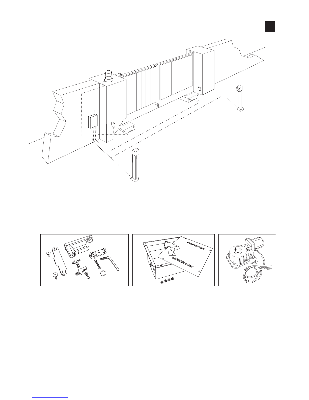
SUB-110
SUB300B
SUB300M-24
1
SUB324M
Page 18
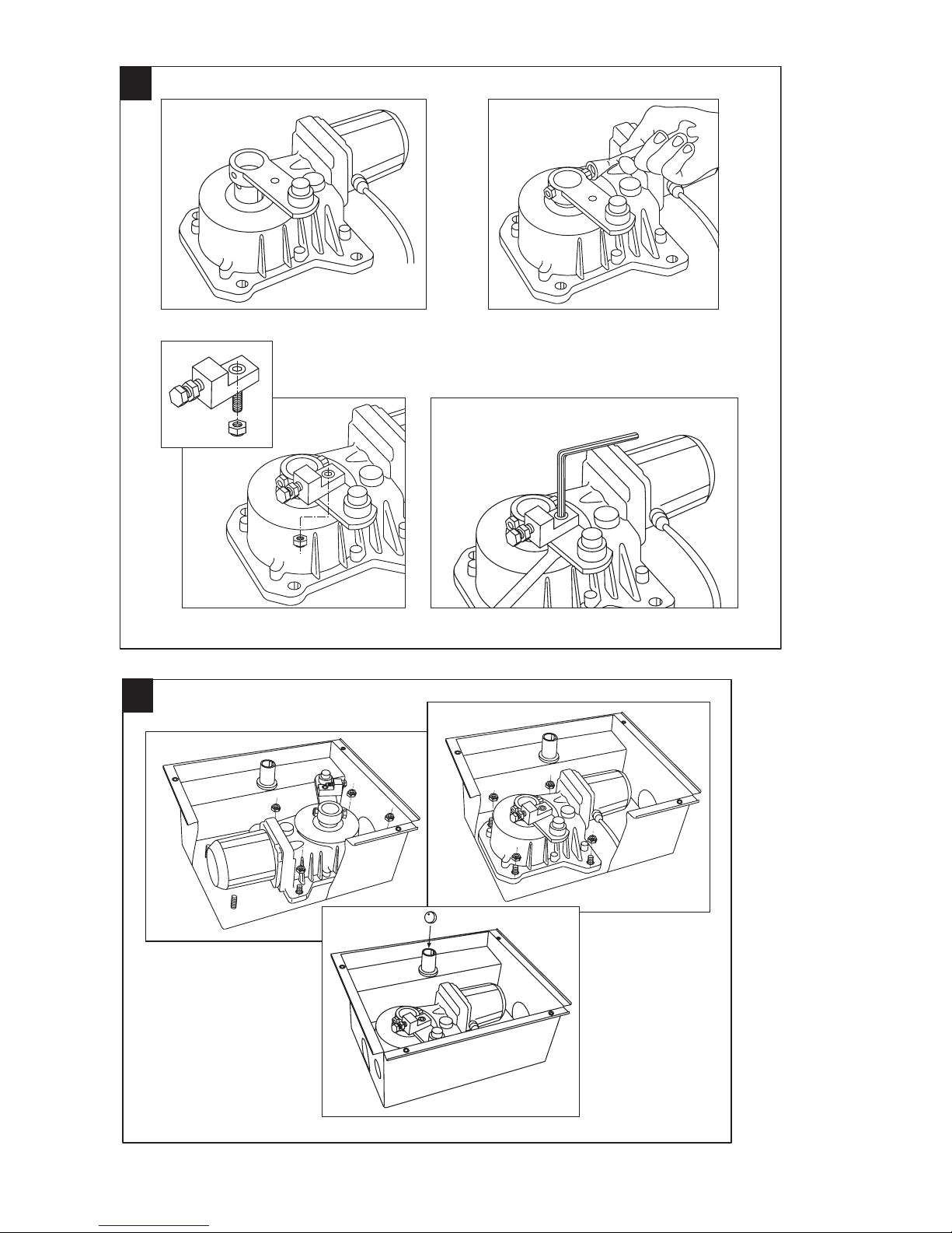
2
3
Page 19
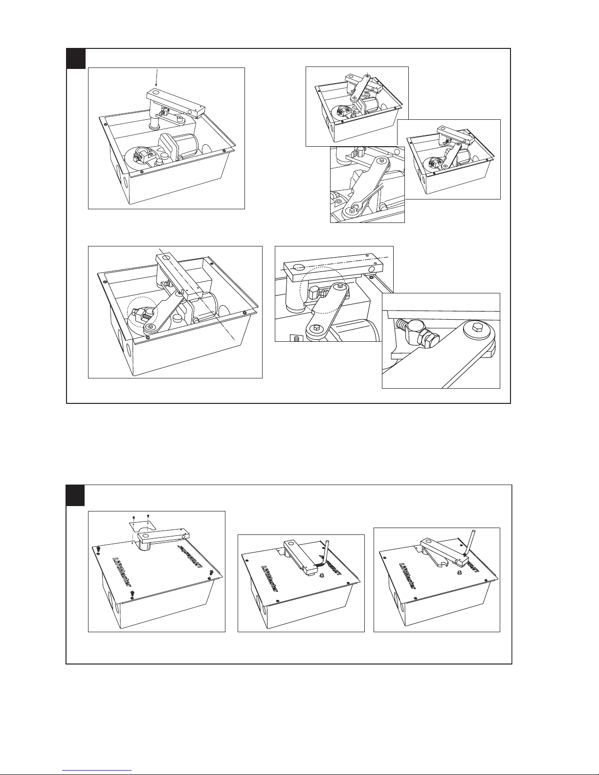
4
4
A
B
Page 20
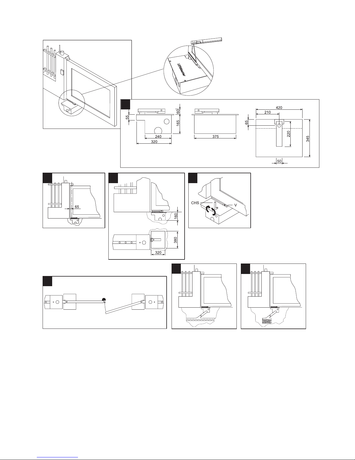
709356B © Chamberlain GmbH, 2008
5
6 7 8
9
10
10
A
B
Page 21
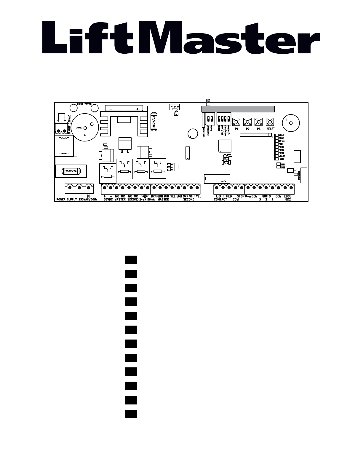
®
Anleitung CB124EV
Instruction CB124EV
Instruction CB124EV
Návody CB124EV
Instrucciones CB124EV
Instruktioner CB124EV
Útmutatók CB124EV
Upute CB124EV
Istruzioni CB124EV
Instruktie CB124EV
Obrázky CB124EV
Instrukcja CB124EV
de
fr
en
cs
es
sv
hu
hr
it
nl
sk
pl
RADIO MODULE
Page 22

THEMA SEITE
SICHERHEITSREGELN . . . . . . . . . . . . . . . . . . . . . . . . . . . . . . . . . . . . . . . . . . . . . . . . . . . . . . . . . . . . . . . . . . . . . . . . . . . . . . . .1
TECHNISCHE DATEN MOTORSTEUERUNG . . . . . . . . . . . . . . . . . . . . . . . . . . . . . . . . . . . . . . . . . . . . . . . . . . . . . . . . . . . . . .2
TYPISCHER AUFBAU EINER ANLAGE . . . . . . . . . . . . . . . . . . . . . . . . . . . . . . . . . . . . . . . . . . . . . . . . . . . . . . . . . . . . . . . . . . .2
INSTALLATION DER STEUERUNG . . . . . . . . . . . . . . . . . . . . . . . . . . . . . . . . . . . . . . . . . . . . . . . . . . . . . . . . . . . . . . . . . . . . . . 2
VORBEREITEN DER STEUERUNG . . . . . . . . . . . . . . . . . . . . . . . . . . . . . . . . . . . . . . . . . . . . . . . . . . . . . . . . . . . . . . . . . . . . . . 2
EMPFOHLENE VORGEHENSWEISE . . . . . . . . . . . . . . . . . . . . . . . . . . . . . . . . . . . . . . . . . . . . . . . . . . . . . . . . . . . . . . . . . . . . . 3
VERKABELUNG DER STEUERUNG . . . . . . . . . . . . . . . . . . . . . . . . . . . . . . . . . . . . . . . . . . . . . . . . . . . . . . . . . . . . . . . . . . . . . 4
ANSCHLUSSDIAGRAMM . . . . . . . . . . . . . . . . . . . . . . . . . . . . . . . . . . . . . . . . . . . . . . . . . . . . . . . . . . . . . . . . . . . . . . . . . . . . . .5
BESCHREIBUNG / FUNCTION DER ANSCHLÜSSE . . . . . . . . . . . . . . . . . . . . . . . . . . . . . . . . . . . . . . . . . . . . . . . . . . . . . . . . .6
BESCHREIBUNG DER LEDS . . . . . . . . . . . . . . . . . . . . . . . . . . . . . . . . . . . . . . . . . . . . . . . . . . . . . . . . . . . . . . . . . . . . . . . . . . . 6
BESCHREIBUNG DER TASTEN P1, P2, P3 & RESET. . . . . . . . . . . . . . . . . . . . . . . . . . . . . . . . . . . . . . . . . . . . . . . . . . . . . . . . 6
OPTIONALES ZUBEHÖR . . . . . . . . . . . . . . . . . . . . . . . . . . . . . . . . . . . . . . . . . . . . . . . . . . . . . . . . . . . . . . . . . . . . . . . . . . . . . . 7
LICHTSCHRANKE . . . . . . . . . . . . . . . . . . . . . . . . . . . . . . . . . . . . . . . . . . . . . . . . . . . . . . . . . . . . . . . . . . . . . . . . . . . . . . . . . . . .8
PROGRAMMIERUNG DER HANDSENDER . . . . . . . . . . . . . . . . . . . . . . . . . . . . . . . . . . . . . . . . . . . . . . . . . . . . . . . . . . . . . . . .8
PROGRAMMIEREN DER INTERNET SCHNITTSTELLE myQ / DER TORÜBERWACHUNG . . . . . . . . . . . . . . . . . . . . . . . . . 9
GEBRAUCH DER SCHLEIFENDETEKTOREN . . . . . . . . . . . . . . . . . . . . . . . . . . . . . . . . . . . . . . . . . . . . . . . . . . . . . . . . . . . . . 10
DIP SCHALTER . . . . . . . . . . . . . . . . . . . . . . . . . . . . . . . . . . . . . . . . . . . . . . . . . . . . . . . . . . . . . . . . . . . . . . . . . . . . . . . . . . . . . .11
EINSTELLEN DER FLÜGELVERZÖGERUNG . . . . . . . . . . . . . . . . . . . . . . . . . . . . . . . . . . . . . . . . . . . . . . . . . . . . . . . . . . . . . .11
ERSTE INBETRIEBNAHME . . . . . . . . . . . . . . . . . . . . . . . . . . . . . . . . . . . . . . . . . . . . . . . . . . . . . . . . . . . . . . . . . . . . . . . . . . . . 12-14
AUTOMATISCHES SCHLIESSEN . . . . . . . . . . . . . . . . . . . . . . . . . . . . . . . . . . . . . . . . . . . . . . . . . . . . . . . . . . . . . . . . . . . . . . . .14
KRAFTBEDARF DES MOTORS . . . . . . . . . . . . . . . . . . . . . . . . . . . . . . . . . . . . . . . . . . . . . . . . . . . . . . . . . . . . . . . . . . . . . . . . .14
ENTSORGUNG / BATTERIEENTSORGUNG . . . . . . . . . . . . . . . . . . . . . . . . . . . . . . . . . . . . . . . . . . . . . . . . . . . . . . . . . . . . . . .14
DIAGNOSE LED . . . . . . . . . . . . . . . . . . . . . . . . . . . . . . . . . . . . . . . . . . . . . . . . . . . . . . . . . . . . . . . . . . . . . . . . . . . . . . . . . . . . . 15
HÄUFIG GESTELLTE FRAGEN . . . . . . . . . . . . . . . . . . . . . . . . . . . . . . . . . . . . . . . . . . . . . . . . . . . . . . . . . . . . . . . . . . . . . . . . .16
Page 23
1/16 de
WARNUNG / ACHTUNG
WICHTIGE ANWEISUNGEN ZUR MONTAGE UND NUTZUNG
BEGINNEN SIE MIT DEM LESEN DIESER WICHTIGEN SICHERHEITSREGELN
Solche Warnzeichen bedeuten “Vorsicht!”, eine Aufforderung zur Beachtung, da ihre Mißachtung Personen- bzw.
Sachschäden verursachen kann. Bitte lesen Sie diese Warnungen sorgfältig.
Dieser Torantrieb ist so konstruiert und geprüft, daß er bei Installation und Benutzung unter genauer Befolgung
der anschließenden Sicherheitsregeln angemessene Sicherheit bietet.
Die Nichtbeachtung der folgenden Sicherheitsregeln kann ernsthafte Personen- oder Sachschäden verursachen.
Beim Umgang mit Werkzeugen und Kleinteilen
Vorsicht walten lassen und weder Ringe, Uhren
noch lose Kleidungsstücke tragen, wenn Sie
Installations- oder Reparaturarbeiten an einem
Tor vornehmen.
Elektrische Leitungen sind entsprechend den
lokalen Bau- und Elektroinstallationsvorschriften zu verlegen. Das elektrische Kabel darf nur
von einer autorisierten Elektrofachkraft an ein
ordnungsgemäß geerdetes Netz angeschlossen
werden.
Bei der Montage muß ein Einklemmen zwischen
dem angetriebenen Teil und den umgebenden
Teilen des Gebäudes (z.B. eine Wand) aufgrund
der Öffnungsbewegung des angetriebenen Teils
vermieden werden.
Entfernen Sie bitte alle am Tor angebrachten
Schlösser, um Schäden am Tor zu vermeiden.
Nach der Installation ist zu prüfen, ob der
Mechanismus richtig eingestellt ist und ob der
Antrieb, das Sicherheitssystem und die
Notentriegelung richtig funktionieren.
Ist ein Gehtor im Tor vorhanden, darf der Antrieb
nicht starten oder weiter laufen, wenn das Tor
nicht ordnungsgemäss geschlossen ist.
Beim Betrieb darf das Tor unter keinen
Umständen öffentliche Durchgangswege
behindern.
Zur Vermeidung von Schäden an sehr leichten
Toren ist eine entsprechende Verstärkung
anzubringen. Wenden Sie sich hierzu
bitte an den Hersteller des Tores.
Betätigen Sie den Antrieb nur, wenn Sie das Tor
voll im Blickfeld haben und sich dort keine
behindernden Gegenstände befi nden. Kinder
sollten nicht in Tornähe bei Betätigung des
Antriebes spielen.
Feuchtigkeit und Wasser zerstören die
Steuerung. Stellen Sie unter allen Umständen
sicher, dass Wasser, Feuchtigkeit oder
Staunässe nicht in die Steuerungsabdeckung
gelangen können.
Es ist wichtig, das Tor immer gut gangbar zu
halten. Tore, die steckenbleiben oder
verklemmen, sind unverzüglich zu reparieren.
Versuchen Sie nicht, das Tor selbst zu
reparieren. Bestellen Sie hierfür einen
Fachmann.
Entfernen Sie zusätzliches Zubehör aus der
Nähe von Kindern. Erlauben Sie Kindern nicht,
Drucktaster und Fernbedienungen zu bedienen.
Schwere Verletzungen können durch ein sich
schließendes Tor verursacht werden.
Automatisch gesteuerte Geräte müssen vom
Netz getrennt werden, wenn Wartungsarbeiten
wie zum Beispiel Reinigung ausgeführt werden.
In der festverlegten Installation ist eine Trennvorrichtung vorzusehen, um ein allpoliges
Abschalten mittels Schalter (mind. 3mm
Kontaktöffnungsweg) oder separate Sicherung
zu gewährleisten.
Stellen Sie sicher, daß Personen, die den Antrieb
montieren, warten oder bedienen, diesen
Anleitungen folgen. Bewahren Sie die Anleitung
an einem Ort auf, an dem schnell auf sie
zurückgegriffen werden kann.
Der endgültige Schutz vor Quetsch- und
Scherstellen muss nach der Montage des
Antriebes mit dem Tor gewährleistet sein.
Diese Anlage darf nicht von Personen bedient
werden (einschliesslich Kindern), die körperlich
oder geistig beeinträchtigt sind, oder denen es
an Erfahrung im Umgang mit der Anlage mangelt, solange sie nicht unter Aufsicht sind oder
von einer für ihre Sicherheit verantwortlichen
Person im Umgang mit der Anlage unterwiesen
worden sind.
Kinder sollten beaufsichtigt werden um
sicherzustellen, dass sie nicht mit der Anlage
spielen.
Automatischer Torantrieb - Nicht im Torbereich
aufhalten, da das Tor unerwartet betrieben
werden könnte.
Diese Anleitung ist aufzubewahren!
Page 24
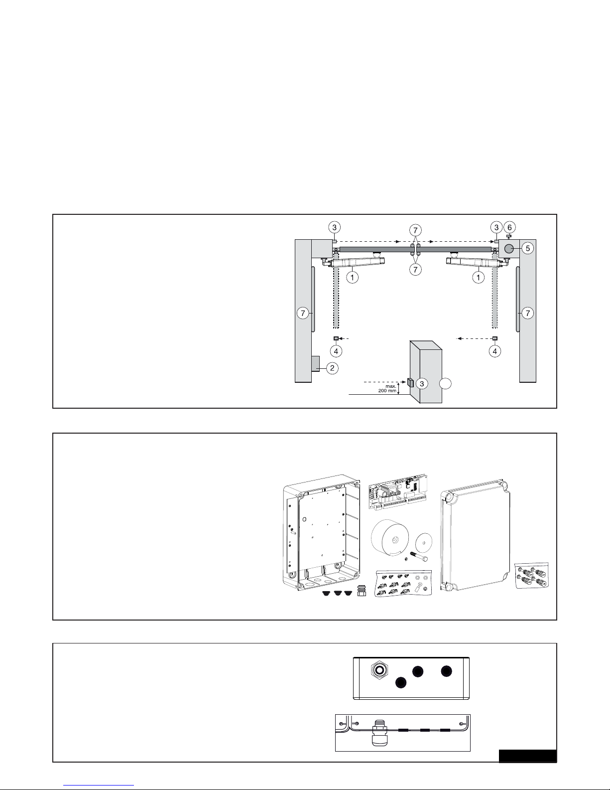
TECHNISCHE DATEN DER MOTORSTEUERUNG
Spannung: 230V~+/- 10% 50-60Hz
Transformator: 230/24VAC, 150VA
Ausgang Motor: 24VDC
Verbrauch max.: max. 400W (in Betrieb)
Verbrauch Standby: max. 4W (ohne Zubehör)
Versorgung Zubehör: 24VDC / 600mA max.
Arbeitstemperatur: -20ºC ÷ +55ºC
Arbeitsweise: Standard, Automatik
Abmessungen: 250x75mm (ohne Box)
Abmessungen Box: ca. 300x220x120mm
Schutzgrad: IP45
Sicherung: 2 x 2A (fl ink)
Handsender: max. 170 x Rolling Code
mögliche Frequenzen: 433MHz, 868MHz
TYPISCHER AUFBAU EINER ANLAGE:
1. Motor
2. Steuerung
3. Lichtschranke (aktiv in Schließen), Höhe max. 200 mm
Erste Lichtschranke.
4. Lichtschranke (aktiv in Öffnen/Schließen), Höhe max. 200 mm
Zweite Lichtschranke (optional).
5. Blinkleuchte (optional)
Wichtiger optischer Hinweis auf die Bewegung des Tores.
6. Schlüsselschalter oder Codeschloss (optional)
Wird an der Aussenseite angebracht. Mittels Schlüssel
oder Eingabe einer Nummer wird das Tor geöffnet.
7. Kontaktleiste (optional)
Sichert das Tor bei Berührung ab. Kontaktleisten können
am Tor oder an den Pfeilern angebracht werden .
Kontaktleisten müssen, wenn erforderlich, bis zu einer
Höhe von 2,5 m angebracht werden.
2/16 de
MONTAGE DER STEUERUNGSBOX
Die Steuerung besteht aus mehreren Komponenten.
- Gehäuse 1
- Deckel für Gehäuse 1
- Steuerung 1
- Transformator 1
- Montageplatte (vormontiert) 1
- Zugentlastung groß 1
- Zugentlastung klein 3
- Halteclips 6
- Schrauben 3,5mm x 9,5mm 4
- große Unterlegscheibe 1
- lange Schraube 1
- Kabelöse 1
- Mutter M8 2
- Unterlegscheibe M8 1
- große Verschlussschrauben 5
VORBEREITEN DER STEUERUNGSBOX
Öffnen Sie z.B. mit einem Schraubendreher die
4 Löcher im Boden des Gehäuses. Die große
Zugentlastung links befestigen, die restlichen wie
gezeigt. Feuchtigkeit und Wasser zerstören die
Steuerung. Alle Öffnungen und Zugentlastungen
müssen unbedingt wasserdicht verschlossen sein.
Die Steuerungsbox mit der Motorsteuerung ist mit
den Zugentlastungen nach unten zu montieren.
4
+
Page 25
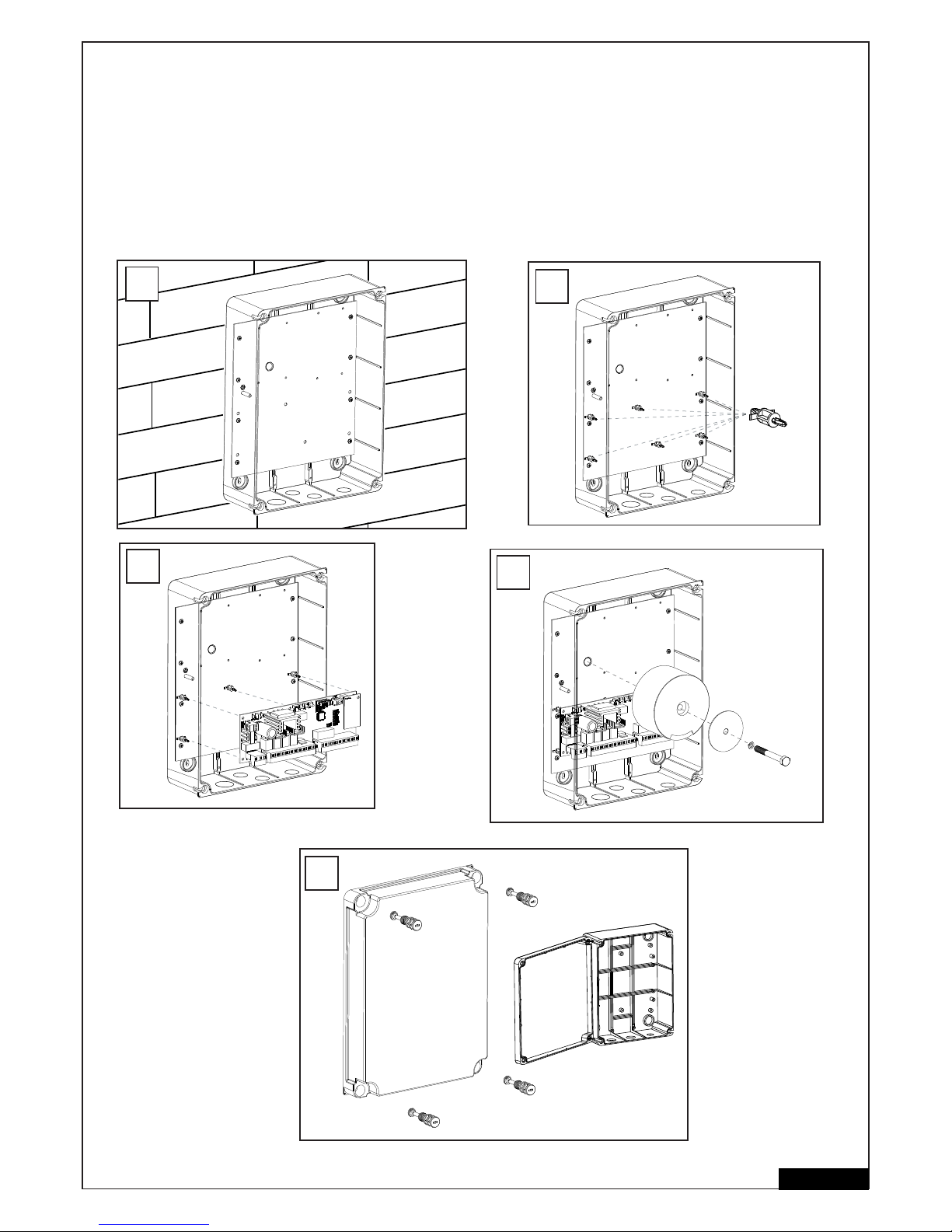
EMPFOHLENE VORGEHENSWEISE
Erforderliche Abstände abmessen und passende Bohrlöcher bestimmen. Gehäuse an die Wand schrauben (Befestigungsmaterial nicht
enthalten). Die Montageplatte ist bereits im Gehäuse montiert. (A)
Halteclips in die vorgesehen Löcher eindrücken. (B)
Steuerung auf die Halteclips drücken. (C)
Den Transformer mit der großen Schraube und der großen Unterlegscheibe auf die Montageplatte schrauben. (D)
Die 4 Verschlussschrauben durch die Öffnungen im Deckel drücken und diesen auf das Gehäuse aufsetzen. Zwei Verschlussschrauben (links
oder rechts) etwa 2cm eindrehen. Danach kann man den Deckel zur Seite klappen. (E)
Schliessen Sie das Gehäuse versuchsweise indem Sie alle Schrauben komplett eindrehen. Sollte hierbei der Deckel das Gehäuse nicht
vollständig schliessen, ist dieses nicht ebenmässig an die Wand montiert und somit verformt. Korrigieren Sie den Sitz des Gehäuses, da der
wasserdichte Verschluss gewährleistet sein muss.
3/16 de
6x
B
C
D
A
E
Page 26
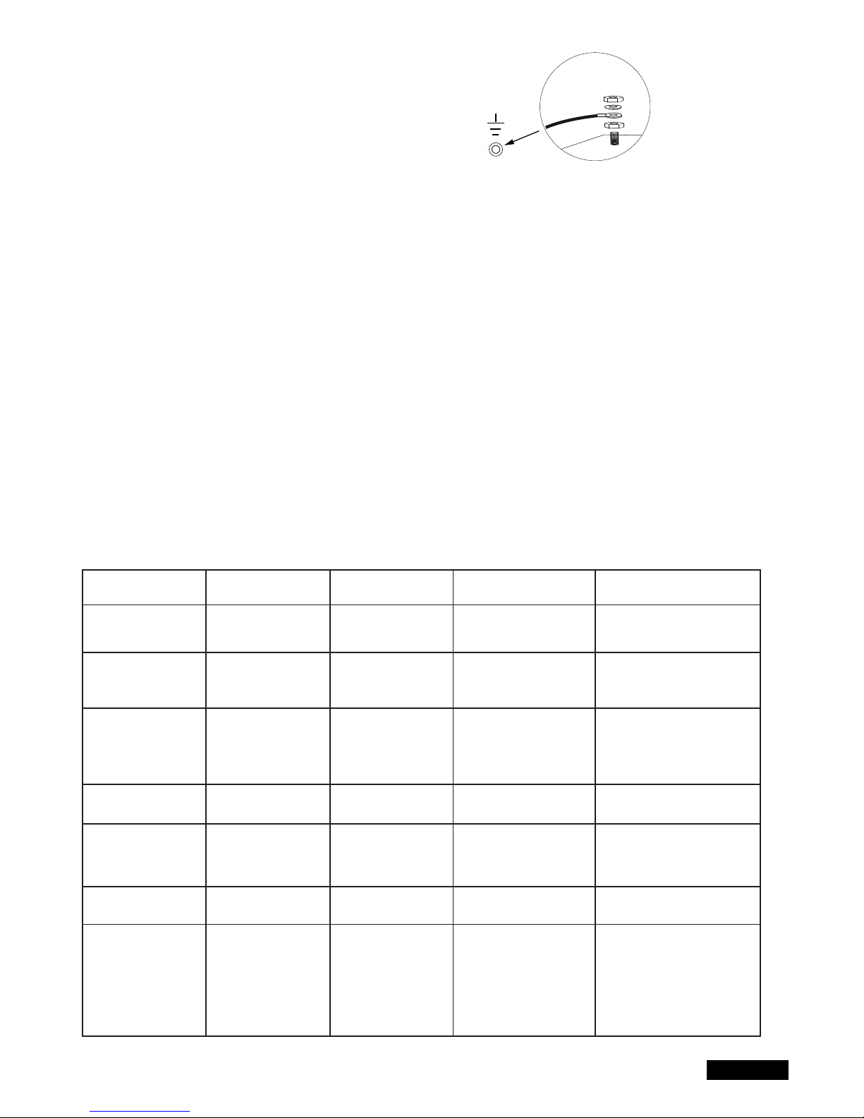
VERKABELN DER STEUERUNG / ÜBERSICHT:
a. Beginnen Sie mit dem noch spannungslosen 230Volt
Zuleitungskabel an der linken Seite der Box.
b. Kabelöse am Erdungsleiter anbringen.
Verbinden Sie den Erdungsleiter der Zuleitung mit der Grund platte (wie im Bild gezeigt). Schließen Sie alle anderen Kabel
an die Steuerung an.
KABEL UND VERDRAHTUNG
Der Gebrauch abgeschirmter Kabel vom Motor zur Steuerung ist empfehlenswert.
Magnetischer und induktiver Einfl uss im Kabel kann Summen hervorrufen und die Funktion des Tores stören.
Vermeiden Sie generell:
- die Steuerung zu weit weg vom Tor anzubringen.
- 230Volt Und Niederspannungsleitungen zusammen zu verlegen. Nach Elektroinstallationsvorschrift nicht zulässig.
- Kabel für Lichtschranken, Schalter, Blinklampe und Elektroschloss nicht zusammen mit dem Motorkabel verlegen.
- Telekommunikationskabel oder Leitungen für Gartenbeleuchtung ebenfalls nicht mit dem Motorkabel verlegen.
- Starre Kupferkabel sind speziell bei größeren Kabeldurchmessern schwer zu verdrahten. Benutzen Sie fl exibele Kabel.
- Benutzen Sie Kabel, die für aussen und die Verlegung im Erdreich geeignet sind oder entsprechende Leerrohre oder fragen Sie ihren Elektriker.
Wir empfehlen das folgende Zubehör:
- LA400-JB40E Kit Kit zur Kabelverlängerung für eine Anlage. Bestehend aus 12m Kabel, 6-polig mit gleichen Farben wie Antrieb, Verteilerdose
IP65, Kabelverschraubungen und Befestigungsmaterial.
- 041ASWG-0482-50 50m Ring Anschlusskabel, 6-polig für den Aussenbereich. Verlegung ohne Leerrohr möglich. Mit gleichen Farben wie am
Antrieb.
Kabelgrößen:
Die Abmessungen in der Tabelle sind Mindestgrößen. Größere Durchmesser sind jederzeit möglich
- 230Volt Versorgungsspannung für die Steuerung: min. 0,75mm² 3-polig
- 230Volt Versorgung für Transformator getrennt installiert (e.g. in der Garage) und Kleinspannung zum Tor. Siehe Tabelle.
- Motorverkabelung: 2 Kabel min. 1,0mm², 4 Kabel min. 0,75mm² (oder abgeschirmte Kabel)
- Elektrisches Schloss: Siehe Tabelle
- Schalter, Lichtschranken, Blinklampe: Siehe Tabelle etc. min.0,5mm²
4/16 de
Antriebsmodell
LYN, SCS, ART
Motorverkabelung
SUB (Unterfl urantrieb)
Motorverkabelung
Separat installierter
Transformator (in der
Garage) und Niederspannungsversorgung
der Steuerung
Elektroschloss (12Volt)
Verkabelung
Externe Antenne
(Entfernen Sie die
Originalantenne von der
Steuerung)
Schalter, Blinklampe etc.
Lichtschranke
Entfernung
0m - 6m
2 x 1,0mm²
4 x 0,75mm²
2 x 1,0mm²
3 x 0,75mm²
0,75mm²
0,75mm²
Koaxialkabel
50 Ohm
0,5mm²
0,5mm²
Entfernung
6m - 10m
2 x 1,0mm²
4 x 0,75mm²
2 x 1,0mm²
3 x 0,75mm²
0,75mm²
0,75mm²
Koaxialkabel
50 Ohm
0,5mm²
0,5mm²
Entfernung
10m - 12m
Normal
Verkabelung
Abgeschirmte Kabel für
die 3 kleineren
Motorkabel benutzen
1,0mm²
1,0mm²
Koaxialkabel
50 Ohm
0,75mm²
0,75mm²
Entfernung
12m – xx
Max. 15m
Abgeschirmte Kabel für die 4
kleineren Motorkabel benutzen
Abgeschirmte Kabel für die 3
kleineren Motorkabel benutzen
Max. 30m; Min. 1,5mm²
Torgewicht maximal 50% der
maximalen Motorleistung
Max. 30m; Min. 1,5mm²
Koaxialkabel
50 Ohm
(max. 25m)
Min. 0,75mm²
Max. 30m
Min. 0,75mm²
Max. 20m
Page 27
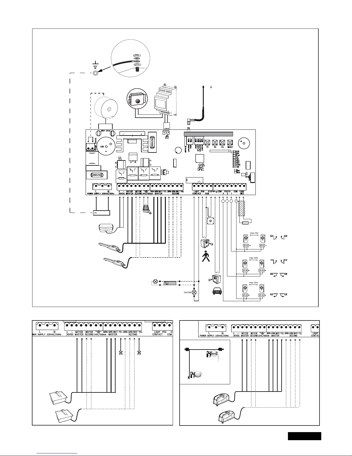
5/16 de
ANSCHLUSSPLAN
LYN/SCS
230VAC
PE
PE
Model
203285
Ω
8.2
+
+
+
+
+
+
+
Relay
+++
+
-
RED
RED
BLUE
BLUE
Model
CM475
BROWN
GREEN
WHITE
BROWN
GREEN
WHITE
YELLOW
YELLOW
RADIO MODULE
Model
207399
230 VAC
50
RED
RED
BLUE
BLUE
BROWN
GREEN
WHITE
BROWN
GREEN
WHITE
not required
not required
RED
RED
BLUE
BLUE
BROWN
GREEN
WHITE
BROWN
GREEN
WHITE
YELLOW
YELLOW
ART
SUB
Closed position
Open position
externe
Batterie
Page 28
Funktionen der Drucktaster P1, P2, P3 & RESET
P1+P2+P3
P1
P1 + P2
P2 + P3
P1 + P3
P2
P3
DIP „RADIO“ + P1
DIP „RADIO“ + P2
RESET
Einzelbetrieb. Die Flügel können einzeln bewegt werden. FunKtion aktivieren: P1+P2+P3 gleichzeitig drücken. Die LEARN-LED
blinkt solange die Funktion aktiviert ist. Taste P1 bewegt Motor1. Taste P2 bewegt Motor2. Funktion deaktivieren: 20
Sekunden warten oder die Steuerung abklemmen. Wenn die Flügel zuerst schliessen, vertauschen Sie die Kabel rot und blau.
Programmiert automatisch die Endpositionen des Laufwegs
Programmiert automatisch die Endpositionen des Laufwegs (sowie zusätzliche Positionen z.B. Soft-Start und Soft-Stop).
Verzögerung Elektroschloss
Einstellung der Flügelverzögerung
Automatisch Schliessen. Zum Bestätigen Taste P2 notwendig
Software-Reset zur Werkseinstellung. Taste 10 Sekunden lang drücken. Das Reset betrifft nicht den Funkspeicher (siehe Funk)
Programmierung der Handsender für Kanal 1. Signal für komplettes Öffnen
Programmierung der Handsender für Kanal 2. Signal für teilweises Öffnen
Internet Schnittstelle oder Torüberwachung programmieren: Hinweis: Die RESET Taste führt kein Reset zur Werkseinstellung
bei dieser Steuerung aus. Sie dient einzig zum Programmieren der Internet Schnittstelle oder der Torüberwachung.
Siehe Beschreibung der Taste P3 für ein Reset zur Werkseinstellung.
Taste Funktion
6/16 de
BESCHREIBUNG DER ANSCHLÜSSE
BESCHREIBUNG FUNKTION
L Anschluss L 230Volt Zuleitung
N Anschluss N 230Volt Zuleitung
30VDC Anschluss einer externen Batterie
Motor MASTER Motor 1 (Master, öffnet als erster)
Motor SECOND Motor 2 (Second, öffnet als zweiter)
Zur Überprüfung der korrekten Polarität siehe Abschnitt
“Grundeinstellung” und “Funktion der Drucktaster P1,P2,P3 & RESET”
24V /150mA Blinkleuchte (Zubehör)
MASTER Motor1
BRN Kabel Braun
GRN Kabel Grün
WHT Kabel Weiss
YEL Kabel Gelb
SECOND Motor2
BRN Kabel Braun
GRN Kabel Grün
WHT Kabel Weiss
YEL Kabel Gelb
Light Contact Torüberwachung/Gartenbeleuchtung
PED Anschluss Schlüsselschalter
COM Minuspol
STOP Notaus / Stopschalter
„Schlüsselsymbol“ Schlüsselschalter
COM Minuspol
PHOTO 3 Lichtschranke 3 (öffnen)
PHOTO 2 Lichtschranke 2 (schliessen & öffnen)
PHOTO 1 Lichtschranke 1 (schliessen)
COM Minuspol
EDGE Kontaktleiste mit 8,2kOhm
8,2KOhm
„Symbol“ E-Schloss Eingang Elektroschloss „Steuereingang“
INPUT 24VAC 24Volt Eingangspannung vom Trafo.
Kann mit beliebiger Polarität
angeschlossen werden
Transformer 230VAC 230Volt Zuleitung zumTransformator.
Kann mit beliebiger Polarität
angeschlossen werden.
250V/2A Sicherung 250V/2A (2x fl ink)
BESCHREIBUNG DER LEDs
BESCHREIBUNG FARBE FUNKTION
STOP Grün Notaus
AN: Notaus aktiv
AUS: OK (Drahtbrücke, wenn kein
Schalter angeschlossen)
EDGE Grün Kontaktleiste 8.2KOhm
AN: aktiviert
AUS: OK (brücken mit 8,2KOhm Widerstand,
wenn keine Kontaktleiste angeschlossen)
„Schlüsselsymbol“ Rot Schlüsselschalter 2-Flügel
AN: Schalter betätigt
AUS: Schalter nicht betätigt
PED Rot Schlüsselschalter 1-Flügel
AN: Schalter betätigt
AUS: Schalter nicht betätigt
PHO1 Rot Lichtschranke 1 (schliessen)
AN: OK (aktiv)
AUS: keine Lichtschranke
PHO2 Rot Lichtschranke 2 (öffnen & schliessen)
AN: OK (aktiv)
AUS: keine Lichtschranke
PHO3 Rot Lichtschranke 3 (öffnen)
AN: OK (aktiv)
AUS: keine Lichtschranke
LEARN Gelb Lernprogramm Status
AN: Lernprogramm aktiv
AUS: Kein Lernprogramm
DGN Rot Diagnose-Programm (siehe Seite 15)
CH1 Rot Programmierung der Handsender für
2-Flügelbetrieb
AN: Neuer Handsender kann
programmiert werden
AUS: Funktion aus
CH2 Rot Programmierung der Handsender für
1-Flügelbetrieb (siehe CH1)
Page 29

7/16 de
OPTIONALES ZUBEHÖR (siehe auch Anschlussplan)
FUNKSTEUERUNGEN (OPTIONAL) MODELLE:
TX2EV, TX4EV, TX4UNI (Handsender), 747EV (Funkcodeschloss), 128EV (Funkwandkonsole)
BLINKLAMPE (OPTIONAL) Modell: FLA24-2, FLA1-LED
Eine Blinkleuchte kann an die Steuerung angeschlossen werden (Anschlüsse: 24 VDC / 150 mA). Sie warnt Personen vor dem sich
bewegenden Tor. Die Blinkleuchte sollte möglichst hoch und deutlich sichtbar angebracht werden. Die Steuerung liefert ein konstantes Signal,
welches von der Lampe in ein Blinksignal umgewandelt wird.
SCHLÜSSELSCHALTER (OPTIONAL) Modell: 100010, 100027, 100034, 100041
Die Anlage kann mit einem Schlüsselschalter betrieben werden. (Anschlüsse: Schlüsselsymbol und COM)
Siehe auch OPEN/PED unter „DIP Schalter“.
NOTAUS / STOPSCHALTER (OPTIONAL) Modell: 600084
Ein Notaus-Schalter, der das Tor in jeder Richtung anhält, kann an diesen Eingang angeschlossen werden.
KONTAKTLEISTE (OPTIONAL) Modell: 600046, 600053, 600077, 600060
(DIP-Schalter LOOP/EDGE muss aus sein)
An die Steuerung kann eine Kontaktleiste, die nach dem 8,2K Ohm- Prinzip funktioniert, angeschlossen werden, d.h., ein 8,2K Ohm großer
Prüfwiderstand ist am Ende der Kontaktleiste befestigt. Er gewährleistet die ständige Überprüfung des Stromkreises. Die Steuerung wird mit einem
eingebauten 8,2K Ohm Widerstand ausgeliefert. Mehrere Kontaktleisten werden in Reihe geschaltet.
LICHTSCHRANKE (OPTIONAL) MODELLE 771E, 772E:
Der Gebrauch einer Lichtschranke wird empfohlen. Benutzen Sie Modell 771E oder 772E, welches auch Bestandteil des Safety Accessory Kit
APLUS- EV ist.
SAFETY ACCESSORY KIT (OPTIONAL): APLUS-EV
Die Steuerung ist bereits mit einer Standard-Antenne ausgestattet. Für höhere Reichweiten kann eine externe Antenne aus dem
APLUS-EV Zubehör (beinhaltet Lichtschranke 771E, Blinklampe FLA1-LED und Externe Antenne SWG-ANT-EV) wie in der Anschlussübersicht
dargestellt, angeschlossen werden.
myQ (OPTIONAL)
(nur mit Internet Schnittstelle 828EV):
Erlaubt das Bedienen des Tores per Internet oder Smartphone.
TORÜBERWACHUNG (OPTIONAL)
(nur mit Torüberwachung 829EV):
Erlaubt optische und akustische Überwachung der Torposition. Das Tor kann mit diesem Gerät auch geschlossen werden.
BATTERIE (OPTIONAL)
Die Anschlüsse dienen zum Aufl aden einer externen Batterie.
Im Falle eines Stromausfalls versorgt die Batterie den Antrieb mit Energie. Eine voll aufgeladene Batterie kann Energie für mehr als 24h liefern.
Batterien unterliegen der Alterung und verlieren an Kapazität. Tauschen Sie die Batterie je nach Gebrauch alle 2-3 Jahre aus.
ELEKTROSCHLOSS (OPTIONAL)
Die Steuerung bietet die Möglichkeit, ein 12V Elektroschloss zu betreiben. (Anleitung liegt dem E-Schloss bei). Hierzu muss eine Hilfssteuerung
(207399) für das Elektroschloss an der Hauptsteuerung angeschlossen werden. Falls das E-Schloss durch zu viel Druck des Tores nicht öffnet,
kann eine spezielle Funktion programmiert werden: Drücken Sie P2 und P3 gleichzeitig für ca. 5 Sekunden und zählen Sie die hörbaren Klicks.
1Klick = ca. 4 Sekunden Strom zum E-Schloss (Werkseinstellung)
2 Klicks = Tor schliesst für eine Sekunde und öffnet dann. Ferner, nach erreichen der Position Tor geschlossen, drückt der Antrieb kurz um das
Einrasten des Elektroschlosses zu unterstützen. Hinweis: Das Tor muss dazu mit Bodenanschlägen ausgerüstet sein.
TORÜBERWACHUNG ODER BELEUCHTUNG (OPTIONAL)
Die Anschlüsse haben zwei Funktionen abhängig davon ob der DIP Schalter Light / Spy an ist oder nicht. Siehe auch unter
“DIP Schalter” in dieser Anleitung. Der Ausgang hat keine eigene Stromversorgung und darf nur bis 24V belastet werden.
Torüberwachung / Status des Tores (Spy)
Eine LED, eine Lampe (24V / 3W max.) oder ein Relais können an die Klemmen angeschlossen werden, um den Status des Tores anzuzeigen.
LED aus = Tor geschlossen
LED langsam blinkend = Tor öffnet
LED an = Tor offen
LED schnell blinkend = Tor schliesst
Hofbeleuchtung / Beleuchtung für 120 Sekunden
Eine Lampe (24V / 3W max.) oder ein Relais können an die Klemmen angeschlossen werden.
Wenn die Steuerung ein Signal zum Öffnen oder Schliessen bekommt, leuchtet die Lampe für 120 Sekunden und schaltet sich danach automatisch
aus.
Achtung: nur max. 24V/3W an den Klemmen anschliessen oder ein Relais muss dazwischengeschaltet werden.
Page 30
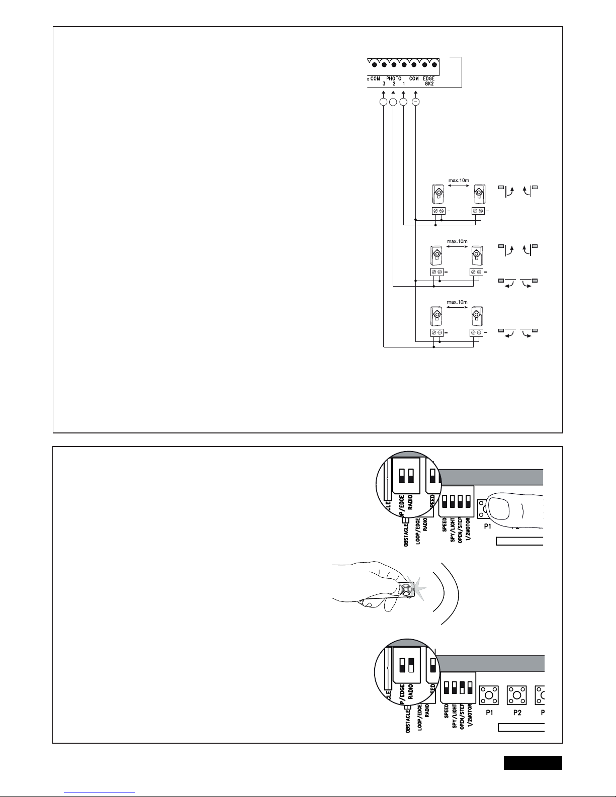
8/16 de
LICHTSCHRANKEN (OPTIONAL) MODELL: 771E, 772E
Die Lichtschranken dienen der Absicherung des Tores und müssen verwendet werden.
Der Montageort ist abhängig von der Bauweise des Tores. Nach EN12453 muß ein
Lichtschrankenpaar aussen in einer Höhe von 200mm aktiv in „Schliessen“ installiert
werden. Die Lichtschranken bestehen aus einem Sender und einem Empfangsteil und
müssen einander gegenüber liegen. Die Lichtschranke wird mittels kleiner Schrauben
und Dübel an der Wand befestigt. Soll die Funktion „Automatisches Schliessen“ möglich
sein, muss die Chamberlain – Failsafe Lichtschranke installiert sein. Das Chamberlain
–Failsafe System (2-Kabel System) besitzt an beiden Seiten eine kleine von außen
einsehbare LED (Licht), um den Status der Lichtschranke anzuzeigen.
Programmierung der Lichtschranke:
- Lichtschranke anschließen
- Wegstreckenprogrammierung der Torfl ügel durchführen
Löschen einer Lichschranke aus der Steuerung:
Eine angeschlossene Lichtschranke kann nicht entfernt werden ohne dass die
Steuerung die Funktion an dem jeweiligen Anschluss sperrt. Um die Lichtschranke aus
dem Programm der Steuerung zu löschen.
- Lichtschranke entfernen
- Strom kurz ausschalten
- Wegstreckenprogrammierung der Torfl ügel durchführen.
Diagnose an der Chamberlain-Failsafe Lichtschranke
LED konstant = OK
LED blinkt = Lichtschranke sperrt Steuerung
LED aus = Kein Strom, falscher Anschluss oder verpolt
Diagnose an der Steuerung
LED aus = OK, keine Lichtschranke angeschlossen
LED blinkt = Steuerung sperrt
Anschluss 1 & COM
Aktiv, wenn das Tor schliesst (reversiert das Tor)
Anschluss 2 & COM
Aktiv, wenn das Tor schliesst und öffnet
Anschluss 3 & COM
Aktiv, wenn das Tor öffnet
(das Tor bleibt solange stehen, bis das Hinderniss aus
dem Infrarotstrahl entfernt wird, danach bewegt es sich weiter)
FUNK
PROGRAMMIEREN / LÖSCHEN VON FRNBEDIENUNGEN
Der Empfänger besitzt 2 Kanäle CH1 und CH2. Die Benutzung der beiden
Kanäle ermöglicht sowohl einfl ügeligen als auch zweifl ügeligen Betrieb.
Beispiel: Erhält CH2 = P2 das Signal der Fernbedienung öffnet sich nur 1
Flügel. Benutzen Sie einen weitere Taste der Fernbedienung mit CH1 = P1
werden beide Flügel geöffnet.
PROGRAMMIERUNG
1: Dip-Schalter “RADIO” anschalten.
2: Drücken Sie kurz die Taste P1(für CH1) oder P2(für CH2) und die
jeweilige LED leuchtet auf.
3: Halten Sie nun die gewünschte Taste auf Ihrer Fernbedienung gedrückt
bis die LED nach kurzem Blinken erlischt. Fertig! Wiederholen Sie diese
Schritte für alle Fernbedienungen (maximal 85 Fernbedienungen
können pro Kanal eingelernt werden).
Wichtig: Nach Programmierung Ihrer Fernbedienung(en) den DIP-Schalter
“RADIO” wieder ausschalten!
Hinweis: Stellen Sie sicher, dass Sie nicht die gleiche Taste Ihrer Fernbedienung auf CH1 und CH2 einlernen; sonst funktioniert die Anlage nicht richtig.
LÖSCHEN
- DIP-Schalter “RADIO” anschalten.
- Halten Sie die Taste P1 so lange gedrückt bis die aufl euchtende LED
nach etwa 10 Sekunden erlischt. Fertig!
Zur Bestätigung blinken beide Leds CH1 und CH2 8 mal.
- DIP-Schalter „RADIO“ ausschalten.
RADIO MODUL
E
ON ON
RADIO MODUL
E
ON ON
RA
ON ON
RA
ON ON
+
+
+
+
+
+
+
+++
Page 31
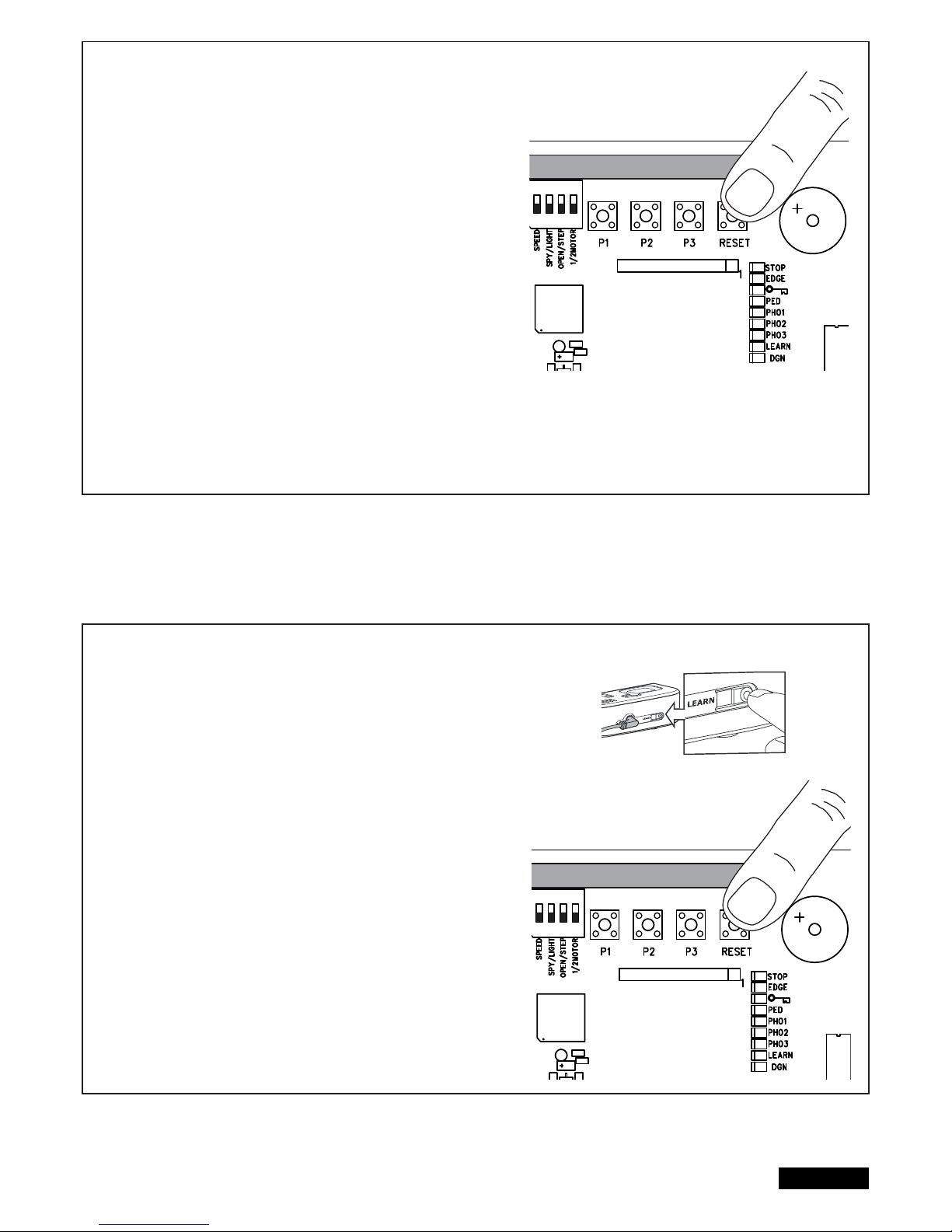
9/16 de
PROGRAMMIEREN DER INTERNET SCHNITTSTELLE myQ
Mit der RESET-Taste auf der Steuerung
1. Die Liftmaster Internet Schnittstelle und ihren Router mit dem Netzwerkkabel
verbinden.
2. Die Liftmaster Internet Schnittstelle mit Strom versorgen.
3. Einen Online Account mit der neuesten Liftmaster myQ Smartphone App oder
auf www.liftmaster.eu einrichten.
4. Die Liftmaster Internet Schnittstelle registrieren.
5. Auf „Neues Gerät hinzufügen“ klicken und den Schritten der App oder der
Webseite weiter folgen.
6. Hinweis: Wenn Sie die RESET-Taste drücken werden Sie einen Piepton hören
und die LEDs CH1 und CH2 zunächst angehen und dann, nach erfolgtem
Abgleich, dreimal blinken und ausgehen.
7. Die App zeigt Ihnen an, ob die Programmierung erfolgreich war und wird Sie
auffordern, einen Namen für das Tor zu vergeben.
PROGRAMMIERUNG DER TORÜBERWACHUNG
Mit der RESET-Taste auf der Steuerung
1. Die Torüberwachung mit Strom versorgen und im Haus so positionieren, dass
sie gut sichtbar ist. Ist der Aufstellort zu weit vom Tor entfernt, kann die
Verbindung gestört oder oft unterbrochen sein. Positionieren Sie das Gerät
an einem besser geeigneten Aufstellort.
2. Die „LEARN“ Taste auf der Rückseite der Torüberwachung kurz drücken und
loslassen. Die rote und grüne LED blinken abwechselnd. Innerhalb 60 Sek
die RESET-Taste auf der Steuerung drücken und loslassen. Zur Bestätigung
der Programmierung gehen die rote und grüne LED an.
Torüberwachung löschen
Die „LEARN“ Taste auf der Rückseite der Torüberwachung für mindestens
10 Sek drücken.
Ein kurzer Piepton bestätigt das erfolgreiche Löschen.
ADIO MODULE
ADIO MODULE
Page 32
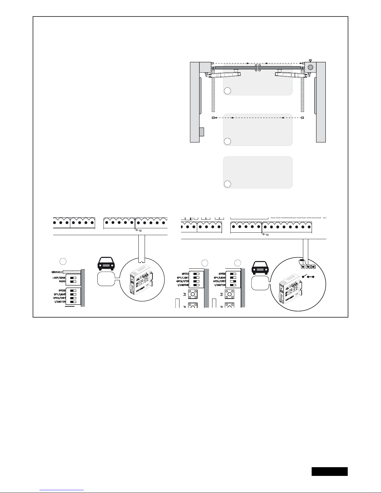
SCHLEIFENDETEKTOREN
(DIP Schalter LOOP/EDGE muss an sein.)
Schleifendetektoren reagieren auf Metall und werden zumeist zur
Erkennung von PKWs und LKWs, aber nicht von Motorrädern und
Fußgängern, eingesetzt.
Ausgangs-Schleife A
Die Ausgangs-Schleife befi ndet sich hinter dem Tor und öffnet das
Tor wenn es geschlossen ist, hält es offen oder öffnet es erneut.
Die DIP Schalter OPEN/STEP und LOOP/EDGE müssen
an sein. Lichtschranken müssen angeschlossen und die
Funktion “Automatisch Schliessen” aktiviert sein.
Sicherheits-Schleifendetektor und
Schleifendetektor im Schwenkbereich des Tores B, C
Schleifendetektoren dienen der Erkennung von Fahrzeugen (PKW,
LKW, aber sind als alleinige Schutzmassnahme unzulässig, da sie
Personen nicht erkennen.
Die Auswerteeinheit der Schleifendetektoren wird als NO
Signalgeber an die Klemmen der 8.2kOhm Kontaktleiste
angeschlossen. Falls Sie auch Kontaktleisten verwenden wollen:
Prüfen Sie vor der Installation welche Funktionsweise für sie
passend ist.
Sicherheits-Schleifendetektor
=> DIP Schalter OPEN/STEP muss an sein.
Schleifendetektor im Schwenkbereich des Tores
=> DIP Schalter OPEN/STEP ausschalten
Weitere Optionen für Schleifendetektoren können bei unserem
Service angefragt werden.
10/16 de
RN WHT YEL
ASTER
BRN GRN WHT YEL
SECOND
COM
PHOTO
3 2 1
C
LIGHT
CONTACT
PED
COM
STOP
NO
Model
203292
Model
203292
RN WHT YEL
ASTER
BRN GRN WHT YEL
SECOND
COM
PHOTO
3 2 1
COM EDGE
8.2KΩ
LIGHT
CONTACT
PED
COM
STOP
NO
COM
NC
A
B
C
A
B C
RADIO
ON ON
RADIO
MOD
ON
RADIO
MOD
ON
Page 33
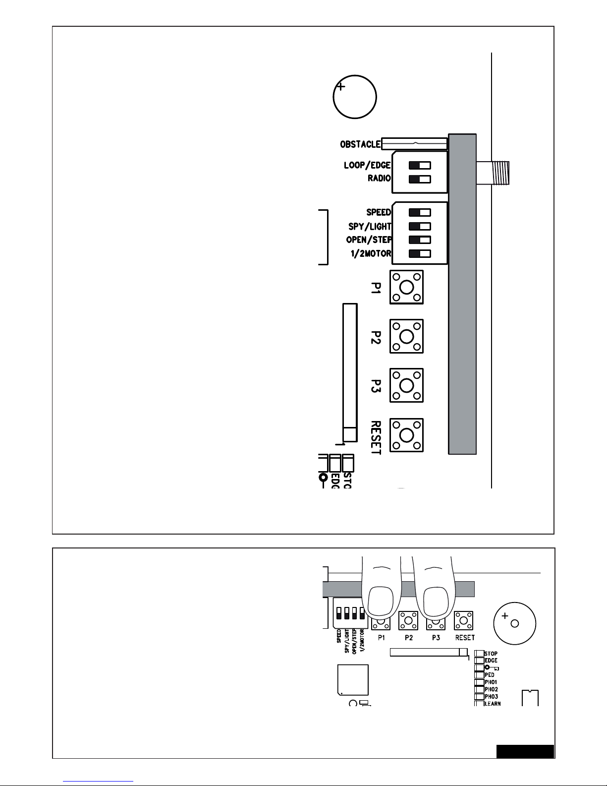
DIP SCHALTER
1 / 2 MOTOR
Wählt aus, ob 1 oder 2 Motoren an der Steuerung angeschlossen sind
AUS: 2 Motoren angeschlossen
AN: 1 Motor angeschlossen
OPEN/STEP
Ändert die Programmierung und Reaktion der Steuerung auf Signale.
Für den Gebrauch mit Schleifendetektoren lesen Sie bitte erst unter
“Schleifendetektoren” nach.
Schritt-Modus: Das erste Signal öffnet das Tor, das nächste stoppt, das
nächste schliesst, das nächste stoppt, das nächste öffnet usw...
Öffnen-Modus: Das Tor wird nicht auf Steuersignale reagieren, solange
es öffnet und die Position OFFEN erreicht hat.
AUS: Schritt-Modus
AN: Öffnen-Modus
LIGHT/SPY
Nur anschalten, wenn die Funktion benötigt wird, ansonsten aus lassen
AUS: LIGHT
AN: SPY
OBSTACLE
Werkseitig mit fester Drahtbrücke ausgestattet. Durchtrennen erhöht
die Arbeitskraft an der Steuerung.
ACHTUNG: Wird die Drahtbrücke durchtennt, muss die Toranlage mit
zusätzlichen Sicherheitseinrichtungen (Kontaktleiste etc.) abgesichtert
werden.
LOOP/EDGE
Wählen Sie die gewünschte Funktion aus
AUS: Kontaktleiste
AN: Schleifendetektor
SPEED
Wählen Sie für den Motortyp aus, den Sie einsetzen wollen.
AUS: ART
AN: LYN, SCS, ART, SUB
RADIO
Der DIP Schalter “RADIO” ist zur Programmierung der Handsender
erforderlich. Den Programmierungsvorgang entnehmen Sie bitte dem
entsprechenden Abschnitt in dieser Anleitung.
AUS: keine Programmierung möglich
AN: Programmierung möglich
WICHTIG: Den DIP Schalter “RADIO” immer ausschalten,
wenn er nicht in Gebrauch ist.
FLÜGELVERZÖGERUNG
Die Flügelverzögerung ist notwendig zum korrekten und sicheren
Öffnen und Schliessen der Flügel. Eine längere Flügelverzögerung
kann erforderlich sein bei unterschiedlichen Installationsbegebenheiten
oder unterschiedlichen Flügellängen.
Drücken und halten Sie P3 und P1 zusammen für etwa 5 Sekunden
und zählen Sie die Anzahl der zu hörenden Klicks. Das Klicken wird
von einem Relais (Lichtrelais) verursacht.
1 Klick = kurze Verzögerung, ca. 4÷8 Sekunden (Werkseinstellung)
2 Klicks = mittlere Verzögerung, ca. 8÷12 Sekunden
3 Klicks = lange Verzögerung, ca. 12÷16 Sekunden
4 Klicks = komplette Verzögerung, Flügel 1 wird erst schliessen,
wenn Flügel 2 komplett geschlossen ist
Die Verzögerung in Öffnen ist immer ca. 3÷5 Sekunden
5 Klicks = keine Verzögerung, beide Flügel Öffnen und Schliessen gleichzeitig
Wiederholen Sie den Vorgang falls erforderlich.
HINWEIS: Programmieren (ändern) des Laufweges setzt die
Flügelverzögerung auf Werkseinstellung zurück.
11/16 de
RADIO MODULE
RADIO MODULE
ON ON
Page 34
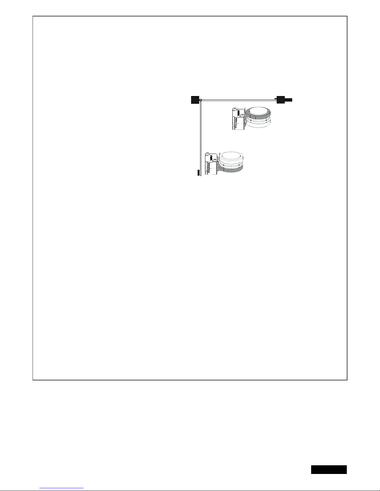
12/16 de
ERSTE INBETRIEBNAHME
GRUNDEINSTELLUNG
Gehen Sie Punkt für Punkt genau durch. Beginnen Sie im Zweifelsfall wieder von vorne. Nehmen Sie sich für diese Einstellungen
ausreichend Zeit.
1. Ist alles Notwendige für den Betrieb angeschlossen? Motoren, Lichtschranken, Sicherheitskontaktleiste, Stop-Schalter.
2. Stellen Sie sicher, dass sich niemand im Torbereich aufhält oder aufhalten kann.
3. Schließen Sie das Tor und hängen Sie die Motoren ein. Sichern Sie die Motoren mit dem Splintbolzen und drehen Sie den
Entriegelungshebel in Richtung Torpfeiler. Die Antriebe sind verriegelt.
ART:
- für eine erfolgreiche Programmierung des Laufweges müssen die
Referenzpunkte eingestellt werden. Hierfür müssen die Nocken unter
der Haube des ART korrekt eingestellt werden. Die obere Nocke soll
den Mikroschalter zuerst auslösen, dann die untere.Die Mikroschlter
sollen nicht gleichzeitig ausgelöst werden oder wenn das Tor die
Endpunkte erreicht hat. Drehen Sie die Nocken mit Hilfe einer Zange
oder eines großen fl achen Schraubendrehers auseinander.
- entriegeln Sie das Tor für diese Einstellungen
- Kontrolle oder Korrektur der richtigen Position der Schalternocken wie
in der Anleitung gezeigt für Tor AUF und Tor ZU.
- Einstellung der DIP Schalter bei Verwendung des ART: DIP Schalter
“SPEED” ausschalten. Der ART wird nicht funktionieren, wenn “SPEED“
an ist.
SUB (Unterfl urantrieb):
- Einstellung der DIP Schalter: “SPEED” an für eine schnellere Torbewegung oder aus, wenn das Tor sehr schwer
ist oder ein sehr sicherer Betrieb erforderlich ist. Kann nach dem Fertigstellen der Installation jederzeit geändert werden.
LYN / SCS Antriebe:
- Einstellung der DIP Schalter: “SPEED” an für eine schnellere Torbewegung oder aus, wenn das Tor sehr schwer
ist oder ein sehr sicherer Betrieb erforderlich ist. Kann nach dem Fertigstellen der Installation jederzeit geändert werden.
Schließen Sie jetzt die Steuerung an das Stromnetz an.
GRUNDEINSTELLUNG:
1. Drücken Sie Taster P1, P2 und P3 gleichzeitig für 2-3 Sekunden, bis die gelbe LED blinkt.
2. Beobachten Sie das Tor. Drücken und halten Sie die Taste P1 für 1-2 Sekunden gedrückt. Das Tor mit Motor 1 muss sich dabei
in Richtung AUF bewegen. (Tor nicht ganz öffnen nur kurze Bewegungen fahren.) Schließt Motor 1 anstatt zu öffnen, ist er falsch
angeschlossen und die Kabel rot/blau am Motor müssen getauscht werden (Achtung: Steuerung vorher stromlos schalten!).
Hinweis: Generelle Funktion - wenn Sie den Taster loslassen, bleibt das Tor sofort stehen. Bei erneutem Drücken läuft es in die
entgegengesetzte Fahrtrichtung, bis Sie den Knopf wieder loslassen usw.
3. Drücken und halten Sie P2 für 1-2 Sekunden. Das Tor mit Motor 2 muss sich dabei in Richtung AUF bewegen. (Tor nicht ganz
öffnen nur kurze Bewegungen fahren.) Schließt Motor 2 anstatt zu öffnen, ist er falsch angeschlossen und die Kabel rot/blau am
Motor müssen getauscht werden (Achtung: Steuerung vorher stromlos schalten!).
Hinweis: Die Steuerung bleibt 20 Sekunden in diesem manuellen Einstellprogramm. Beginnen Sie ggf. wieder von vorne mit
dem gleichzeitigen Drücken der Tasten P1/P2/P3
Überprüfen Sie:
1. Nur bei SCS: Wenn der Flügel öffnet, darf die vordere „Nase“ des Motors das Tor NICHT berühren (stoßen oder schleifen). Das
Öffnen mehrfach unterbrechen und kontrollieren! Im Falle einer Berührung müssen Maß A/B kontrolliert werden und ggf. der
Torbeschlag unterlegt werden, um mehr Abstand zu erhalten.
2. Beide Flügel komplett öffnen. Nicht zu weit fahren! Wenn kein Anschlag in AUF vorhanden ist, markieren Sie den
maximalen Öffnungspunkt.
3. Nur bei SUB (Unterfl urantrieb): Justieren Sie jetzt die mechanischen Endanschläge in der Box.
Warten Sie, bis die Lern LED von alleine ausgeht (20 Sekunden nach dem letzten Tastendruck).
Closed position
Open position
Tor geschlossen
Tor offen
Page 35

13/16 de
PROGRAMMIERUNG DER WEGSTRECKEN EINFACH I
Hinweis: Endanschläge in ZU und AUF müssen vorhanden sein.
1. Die Flügel müssen geschlossen sein.
2. Drücken Sie die Taste P1 solange, bis der Flügel / Motor 1 zu öffnen beginnt. (LED “LEARN” blinkt)
Das Automatik-Programm beginnt (langsame Fahrt):
Flügel 1 fährt bis zum Anschlag AUF.
Flügel 2 fährt bis zum Anschlag AUF.
Danach fährt Flügel 2 bis zum Anschlag ZU und anschließend fährt Flügel 1 bis zum Anschlag ZU.
Wenn LED „LEARN“ erlischt, ist die Programmierung abgeschlossen
Hinweis: Schließen die Flügel anstatt zu öffnen, sind die Motoren falsch angeschlossen. Vertauschen Sie Rot und Blau.
PROGRAMMIERUNG DER WEGSTRECKE: EINFACH II
Hinweis: Wenn kein Endanschlag in Richtung AUF vorhanden ist, sollte der Flügel bei ca. 90° Öffnungswinkel gestoppt werden.)
1. Die Flügel müssen geschlossen sein.
2. Drücken Sie die Taste P1 solange, bis der Flügel / Motor 1 zu öffnen beginnt.
3. Drücken Sie die Taste P1, wenn der Flügel / Motor 1 Position Tor AUF erreicht hat. Der Flügel 2 startet.
4. Drücken Sie die Taste P1, wenn der Flügel / Motor 2 Position Tor AUF erreicht hat. Der Flügel 2 schließt dann
automatisch wieder. Danach schließt Flügel 1 automatisch.
5. Der Antrieb lernt die Position Tor ZU automatisch.
Auf Wunsch können Sie aber auch einen individuellen Punkt in Tor ZU lernen.
Drücken Sie die Taste P1 dann an der gewünschten Tor Zu Position für den jeweiligen Flügel.
Wenn LED „LEARN“ erlischt, ist die Programmierung abgeschlossen.
PROGRAMMIERUNG DER WEGSTRECKE „ADVANCED“ (INDIVIDUELL)
Hinweis: Die Taste P1 muss in diesem Progamm insgesamt 9x gedrückt werden.
Mit jedem Tastendruck wird eine Position (Zeit) gespeichert. Dadurch ist es möglich, Soft-Stopp (Langsamlauf) zu speichern, um
sich dem Tor oder der Anwendung indivudell anzupassen. Lange oder kurze Soft-Stopp Phasen sind möglich.
1. Die Flügel müssen geschlossen sein.
2. P1 und P2 gleichzeitig längere Zeit drücken (ca.5-6 Sek.), bis Flügel 1 startet (öffnet). Tasten loslassen!!
3. P1 wieder drücken; Soft-Stopp in AUF-Richtung für Flügel 1 beginnt ab dieser Position.
4. P1 wieder drücken; Endanschlag AUF erreicht. Automatisch startet jetzt Flügel 2.
5. P1 wieder drücken; Soft-Stopp in AUF-Richtung für Flügel 2 beginnt ab dieser Position.
6. P1 wieder drücken; Endanschlag AUF erreicht. Automatisch startet jetzt Flügel 2 und schließt.
7. P1 wieder drücken; Soft-Stopp in ZU-Richtung für Flügel 2 beginnt ab dieser Position.
8. P1 wieder drücken; Endanschlag in ZU-Richtung erreicht. Automatisch startet jetzt Flügel 1
9. P1 wieder drücken; Soft-Stopp ZU für Flügel 1 beginnt ab dieser Position.
10. P1 wieder drücken; Endanschlag ZU erreicht. ->Fertig
Hinweis: Erreicht ein Flügel einen Endanschlag und die Taste P1 wird NICHT gedrückt, fährt der Antrieb auf den Anschlag und lernt
diese Position selbständig.
Page 36
14/16 de
FERTIGSTELLEN DER INSTALLATION/PROGRAMMIERUNG:
Ist die Wegstrecke programmiert, können die Handsender eingelernt werden (siehe EINLERNEN /LÖSCHEN DER HANDSENDER).
1. Lassen Sie nun das Tor mittels Tastendruck des Handsenders oder eines angeschlossenen Tasters 2 vollständige Zyklen durchlaufen und
beobachten Sie den Ablauf. Schließen Sie das Tor wieder, OHNE dass Sie weitere eine Einstellung vorgenommen haben.
2. Sind alle Einstellungen getroffen worden, überprüfen Sie die Funktion der Lichtschranken, Taster, Blinkleuchte, Handsender, Zubehör etc.
3. Zeigen Sie allen Personen, die Umgang mit dem Tor haben, wie die Bewegungen des Tores ablaufen, wie die Sicherheitsfunktionen arbeiten
und wie das Tor entriegelt und von Hand betätigt werden kann
AUTOMATISCHES SCHLIEßEN DES TORES
Hinweis: Nur möglich mit angeschlossener und funktionsfähiger Lichtschranke (PHOTO + COM).
Es kann eine autmatische Schließzeit zwischen 2 Sekunden und 120 Sekunden gewählt werden.
Einstellen
1. P2 drücken und halten, bis die gelbe LED zu blinken beginnt.
2. Wenn die gelbe LED blinkt, zählen Sie die Öffnungszeit, die programmiert werden soll, ab.
3. Nach Ablauf der Wunschzeit drücken Sie P2 erneut. ->Fertig
Ausschalten
1. P2 drücken und halten, bis die gelbe LED zu blinken beginnt.
2. P3 drücken. Die gelbe LED geht aus. ->Fertig
BETRIEBSSKRAFT DES ANTRIEBS
Die Betriebskraft des Antriebs wird automatisch eingestellt, während
die Wegstrecke programmiert wird. Eine Veränderung (automatisch)
ist nur mit einer erneuten Programmierung der Wegstrecke möglich.
Klemmt das Tor durch Witterungseinfl üsse oder Veränderungen an
der Toranlage (z.B. durch Rost oder unzureichende Schmierung),
muss es ggf. gewartet werden.
Die Steuerung entspricht den neuesten EN-Richtlinien.
Eine dieser Richtlinien schreibt vor, daß die Schließkräfte an der
Torkante innerhalb der letzten 500mm vor Tor ZU nicht über 400 N (40 kg)
steigen dürfen . Größer als 500 mm darf die maximale Kraft an der
Torkante 1400 N (140 kg) betragen. Kann dies nicht sichergestellt werden,
ist unbedingt eine Kontaktleiste ggf. bis in eine Höhe von 2,5 m am Tor
oder am gegenüberliegenden Pfeiler anzubringen (EN12453).
ENTSORGUNG
Die Verpackung besteht aus umweltfreundlichen Materialien. Sie kann in den örtlichen Recyclebehältern entsorgt werden. Gemäß der
Europäischen Richtlinie 2002/96/EG über Elektro-Altgeräte muss dieses Gerät nach Verwendung ordnungsgemäß entsorgt werden um eine
Wiederverwertung der verwendeten Materialien zu gewährleisten.
Über die Möglichkeiten dieser Entsorgung informiert die Gemeinde oder Stadtverwaltung.
BATTERIEENTSORGUNG
Batterien und Akkus dürfen nicht im Hausmüll entsorgt werden. Sie können die Batterien nach Gebrauch
in unmittelbarer Nähe (z.B. im Handel oder in kommunalen Sammelstellen) unentgeltlich zurückgeben.
Batterien und Akkus sind mit einer durchgekreuzten Mülltonne sowie dem chemischen Symbol des
Schadstoffes bezeichnet, nämlich “Cd” für Cadmium, “Hg” für Quecksilber und “Pb” für Blei.
12VDC
Pb Cd Hg
Page 37

15/16 de
ANZEIGE DER “DIAGNOSTIC”-LED
Die Diagnose LED zeigt den zuerst aufgetretenen Fehler an. Sollten weitere Fehler auftreten werden diese möglicherweise nicht angezeigt.
Anzeige
1x blinken
2x blinken
3x blinken
4x blinken
5x blinken
6x blinken
7x blinken
8x blinken
9x blinken
10x blinken
11x blinken
12x blinken
13x blinken
14x blinken
15x blinken
Beschreibung
Antrieb 1 Kontaktfehler eines Steuerkabels zur
Steuerung.
Wie 1x blinken für Antrieb 2
Endpunkte Antrieb 2 wurden nicht akzeptiert.
A: Nach oder in der Lernfahrt: Antrieb 1 wurde nicht
weit genug geöffnet.
B: Kontaktfehler eines Steuerkabels zur Steuerung.
Kabel Gelb oder Weiss hat keinen oder sehr schlechten Kontakt.
Endpunkte Antrieb 1 wurden nicht akzeptiert.
Wegstrecke ist nicht programmiert in der Steuerung.
Kraft, die benötigt wird, um die Flügel zu bewegen,
ist zu hoch.
A: Tor ist defekt
B: Tor ist schwergängig
C: Tor bei Wind stehengeblieben.
Lichtschranke 1 sperrt die Funktion
A: Objekt blockiert die Lichtschranke
B: Ausrichtung der Linsen zueinander ist nicht exakt.
C: Spannungsversorgung zu den Lichtschranken ist
nicht ausreichend
Lichtschranke 2 sperrt die Funktion
Lichtschranke 3 sperrt die Funktion
Not-Aus Schalter sperrt die Anlage
Kontaktleiste sperrt die Anlage
A: Objekt drückt auf Kontaktleiste
B: Kontaktleiste defekt
C: Spannungsversorgung zu niedrig oder Kabelbruch
in der Zuleitung.
Stromzufuhr der Steuerung ist zu gering
A: Zuleitung 230Volt defekt oder Kontakte schlecht
B: Kabelbruch in der Zuleitung (starre Kupferkabel)
C: Die als Zubehör erhältliche Batterie zum Betrieb
bei Stromausfall ist leer.
EEPROM Fehler
Das Hochfahren der Steuerung ist fehlgeschlagen.
Nur LYN/SCS
Motor noch entriegelt
Defekt an einem Relais oder an einem anderen
wichtigen elektronischen Bauteil
A: Überspannung
B: schlechte Verdrahtung (falsch)
C: starke Feuchtigkeit in der Lichtschranke (mangelhafte
Installation)
D: eine Lichschranke wurde vorher angeschlossen,
aber nicht entfernt (abgeklemmt)
Lösung
Kabel Grün oder weiss hat keinen oder schlechten Kontakt.
Anschlüsse genauestens überprüfen. Leitungslängen beachten.
Siehe 1x blinken
Zu A: Tor in der Lernfahrt weiter öffnen. Über 50% des maximalen
Laufwegs.
Zu B: Anschlüsse genauestens überprüfen. Leitungslängen
beachten
Siehe 3x blinken
Lernfahrt der Endpunkte wiederholen
A: Tor reparieren
B: Leichtgängigkeit des Tores prüfen
C: Tor bei starkem Wind nicht betreiben.
D: Lernfahrt der Endpunkte wiederholen, damit die benötigte Kraft
neu gelernt werden kann.
A: Entfernen
B: Überprüfen
C: Überprüfen der Leitungsquerschnitte und der Anschlüsse
Siehe 7x blinken
Siehe 7x blinken
A: Leitung und Verkabelung kontrollieren.
B: Grundeinstellung der Steuerung kontrollieren (DIPs)
A: Entfernen
B: Leitung und Verkabelung kontrollieren. 8.2 KOhm Widerstand
kontrollieren.
C: Grundeinstellung der Steuerung kontrollieren (DIPs)
A: Anschlüsse kontrollieren
B: Kontrolle (Fachmann)
C: Batterie 24 Stunden laden lassen.
A: Steuerung ersetzen
Motor verriegeln
Steuerung austauschen
Verdrahtung überprüfen
Den Laufweg von der Position Tor komplett geschlossen erneut
einlernen
Page 38

16/16 de
HÄUFIG GESTELLTE FRAGEN
Keine Reaktion beim Drücken von P1, P2, P3 Der DIPSchalter “RADIO” muss aus sein.
Der Antrieb reagiert gar nicht, keine LED leuchtet Evtl.Stromausfall 1.Leiter und Nullleiter prüfen
2.Haussicherung prüfen
Direkt nachdem sich das Tor in Bewegung gesetzt Hindernis im Torbereich Torbereich auf Hindernisse prüfen
hat, hält es an und/oder fährt zurück oder Tor schwergängig Lichtschranken kontrollieren
(Fachmann hinzuziehen) Laufweg neu programmieren
Tor läßt sich nur öffnen Lichtschranke sperrt Prüfung der Funktion und des
Anschlusses erforderlich
“Automatisch Schließen” funktioniert nicht Funktioniert nur mit der 2-Kabel-Lichtschranke
771E(ML) oder 772E(ML).
Steuerung funktioniert nicht mehr mit Handsender, Eine Lichtschranke, Kontaktleiste oder Es muss mindestens eine Lichtschranke
nur noch mit Schalter und selbst dann nur, wenn NotStop sperren die Steuerung aktiv in ZU oder AUF angeschlossen sein.
eine Taste gedrückt und gehalten wird. Es wurde nur eine Lichtschranke für
AUF angeschlossen
Der Antrieb reagiert gar nicht, obwohl die 1.Handsender nicht programmiert zu 1: Handsender einlernen
Steuerung angeschlossen ist. (LEDs sind an) 2.LEDs zeigen Fehler an zu 2: siehe Beschreibung “Diagnostic” LED
3.Lichtschranke falsch angeschlossen zu 3: Anschluss/Prog. Lichtschranke überprüfen
4.Klemme für Motor evtl. nicht richtig zu 4: Klemme und Anschlüsse überprüfen
aufgesteckt
Steuerung funktioniert nicht mit Handsender 1.Handsender nicht programmiert zu 1: Handsender programmieren
2.Eine Lichtschranke sperrt zu 2: Lichtschranken prüfen
3. DIP-Schalter“RADIO” zu 3: Schalter muss aus sein
Die Steuerung funktioniert nicht Kein Laufweg gelernt. Siehe erste Inbetriebnahme
Siehe Diagnose LED
Die Flügel öffnen nicht vollständig 1.Kraft zu gering bei hoher Windlast 1.Leichtgängigkeit verbessern
(vollfl ächige Tore) 2.Steuerung neu programmieren
2.Tor schwergängig/schwer
Der Laufweg kann nicht eingelernt werden
Der Antrieb läuft kurzzeitig langsam Stromausfall Normaler Vorgang. Der Antrieb durchläuft nach
einem Stromausfall einen Funktionstest. Dieser
dauert je nach Modell wenige Sekunden oder
einen ganzen Zyklus. Unterbrechen Sie
während des Funktionstests den Antreib nicht
mit dem Handsender oder einem Schalter,
sonst könnten die Endpunkte verschoben
werden. In diesem Fall ist der Laufweg mittels
P1 neu zu programmieren.
Vermeiden Sie unnötige Stromausfälle.
Die Reichweite des Senders ist zu gering Die Installation einer Aussenantenne ist empfehlenswert, da sich die Steuerung mit der
kurzen Kabelantenne in den meisten Fällen hinter dem Pfeiler oder in Bodennähe
befi ndet. Die optimale Antennenposition ist immer so hoch wie möglich. Chamberlain
bietet als Zubehör eine entsprechende Antenne mit Montagesatz an.
Das Tor muß einer Steigung folgen Tor ändern! Das Tor kann sich unkontrolliert (gefährlich) bewegen, wenn der Antrieb
entriegelt ist. In der Steigungsrichtung wird eine höhere Kraft benötigt; in entgegenge setzter Richtung hat der Antrieb dann zuviel Kraft.
1. Einstellung der DIP Schalter ist
nicht korrekt
2. Motorverkabelung falsch oder
defektes Kabel
3. siehe Diagnose LED
4. Störsignal in der Verkabelung
5. Tor bewegt sich während der
Programmierung nur 1 Sekunde und
bleibt dann stehen ohne zu reservieren
6. Nur ART: Einstellung der Referenzpunkte nicht korrekt
7. Nur ART: Motor ist entriegelt
1. Sehen Sie sich in der Anleitung den Punkt
“1/2 Motor” an
2. Wenn der Motor sich bewegt überprüfen
Sie das braune, grüne, weisse und gelbe
Kabel. Probieren Sie ein anderes Kabel aus,
um den Fehler beim im Boden verlegten
Kabel auszuschliessen oder schliessen Sie
hierfür testweise das aus Motor kommende
Kabel direkt an der Steuerung an.
3. Kontrolle der Diagnose LEDs zur
Fehlerbestimmung.
4.Siehe Lösung 2. Falls notwendig, Kabel
tauschen. Siehe auch Punkt “ Kabelgrößen
5. Ungenügende Stromversorgung oder
schlechte Verkabelung. Siehe Lösung 2
6. Stellen Sie die Nocken am Motor korrekt
ein. Siehe ART Anleitung
7. Den Antrieb verriegeln. Siehe ART Anleitung
Der Torpfeiler ist so dick, daß die A+B Maße Pfeiler aussparen oder Tor versetzen
nicht eingehalten werden können.
Page 39

THEME PAGE
REGLES DE SECURITE . . . . . . . . . . . . . . . . . . . . . . . . . . . . . . . . . . . . . . . . . . . . . . . . . . . . . . . . . . . . . . . . . . . . . . . . . . . . . . .1
DONNEES TECHNIQUES DE LA COMMANDE . . . . . . . . . . . . . . . . . . . . . . . . . . . . . . . . . . . . . . . . . . . . . . . . . . . . . . . . . . . . .2
CONFIGURATION TYPIQUE D’ UN INSTALLATION . . . . . . . . . . . . . . . . . . . . . . . . . . . . . . . . . . . . . . . . . . . . . . . . . . . . . . . . .2
INSTALLATION DE LA COMMANDE . . . . . . . . . . . . . . . . . . . . . . . . . . . . . . . . . . . . . . . . . . . . . . . . . . . . . . . . . . . . . . . . . . . . .2
PREPARATION DE LA COMMANDE . . . . . . . . . . . . . . . . . . . . . . . . . . . . . . . . . . . . . . . . . . . . . . . . . . . . . . . . . . . . . . . . . . . . . 2
PROCEDE RECOMMANDE . . . . . . . . . . . . . . . . . . . . . . . . . . . . . . . . . . . . . . . . . . . . . . . . . . . . . . . . . . . . . . . . . . . . . . . . . . . . .3
CABLAGE DE LA COMMANDE . . . . . . . . . . . . . . . . . . . . . . . . . . . . . . . . . . . . . . . . . . . . . . . . . . . . . . . . . . . . . . . . . . . . . . . . . 4
SCHEMA DES CONNEXIONS . . . . . . . . . . . . . . . . . . . . . . . . . . . . . . . . . . . . . . . . . . . . . . . . . . . . . . . . . . . . . . . . . . . . . . . . . . .5
DESCRIPTION / FONCTION DES CONNECTEURS . . . . . . . . . . . . . . . . . . . . . . . . . . . . . . . . . . . . . . . . . . . . . . . . . . . . . . . . . 6
DESCRIPTION DES DEL . . . . . . . . . . . . . . . . . . . . . . . . . . . . . . . . . . . . . . . . . . . . . . . . . . . . . . . . . . . . . . . . . . . . . . . . . . . . . . .6
DESCRIPTION DES TOUCHES P1, P2, P3 & RESET. . . . . . . . . . . . . . . . . . . . . . . . . . . . . . . . . . . . . . . . . . . . . . . . . . . . . . . . .6
ACCESSOIRES EN OPTION . . . . . . . . . . . . . . . . . . . . . . . . . . . . . . . . . . . . . . . . . . . . . . . . . . . . . . . . . . . . . . . . . . . . . . . . . . . .7
BARRIERE PHOTOELECTRIQUE . . . . . . . . . . . . . . . . . . . . . . . . . . . . . . . . . . . . . . . . . . . . . . . . . . . . . . . . . . . . . . . . . . . . . . . 8
PROGRAMMATION DE LA TELECOMMANDE . . . . . . . . . . . . . . . . . . . . . . . . . . . . . . . . . . . . . . . . . . . . . . . . . . . . . . . . . . . . . 8
PROGRAMMATION DE L‘INTERFACE INTERNET MYQ / DE LA SURVEILLANCE DE PORTAIL . . . . . . . . . . . . . . . . . . . . . 9
UTILISATION DES DETECTEURS DE BOUCLES . . . . . . . . . . . . . . . . . . . . . . . . . . . . . . . . . . . . . . . . . . . . . . . . . . . . . . . . . . .10
COMMUTATEURS DIP. . . . . . . . . . . . . . . . . . . . . . . . . . . . . . . . . . . . . . . . . . . . . . . . . . . . . . . . . . . . . . . . . . . . . . . . . . . . . . . . .11
REGLAGE DE LA TEMPORISATION DE VANTAIL . . . . . . . . . . . . . . . . . . . . . . . . . . . . . . . . . . . . . . . . . . . . . . . . . . . . . . . . . . 11
PREMIERE MISE EN SERVICE . . . . . . . . . . . . . . . . . . . . . . . . . . . . . . . . . . . . . . . . . . . . . . . . . . . . . . . . . . . . . . . . . . . . . . . . . .12-14
FERMETURE AUTOMATIQUE . . . . . . . . . . . . . . . . . . . . . . . . . . . . . . . . . . . . . . . . . . . . . . . . . . . . . . . . . . . . . . . . . . . . . . . . . . 14
PUISSANCE REQUISE PAR LE MOTEUR . . . . . . . . . . . . . . . . . . . . . . . . . . . . . . . . . . . . . . . . . . . . . . . . . . . . . . . . . . . . . . . . .14
ELIMINATION / ELIMINATION DES PILES . . . . . . . . . . . . . . . . . . . . . . . . . . . . . . . . . . . . . . . . . . . . . . . . . . . . . . . . . . . . . . . . .14
DEL DE DIAGNOSTIC . . . . . . . . . . . . . . . . . . . . . . . . . . . . . . . . . . . . . . . . . . . . . . . . . . . . . . . . . . . . . . . . . . . . . . . . . . . . . . . . .15
QUESTIONS FREQUEMMENT POSEES . . . . . . . . . . . . . . . . . . . . . . . . . . . . . . . . . . . . . . . . . . . . . . . . . . . . . . . . . . . . . . . . . . 16
Page 40
1/16 fr
AVERTISSEMENT / ATTENTION
INSTRUCTIONS IMPORTANTES POUR LE MONTAGE ET L‘UTILISATION
VEUILLEZ TOUT D‘ABORD LIRE CES REGLES DE SECURITE IMPORTANTES
Ces pictogrammes appellent à la prudence et ont valeur d‘avertissement, car leur non-respect peut entraîner un
risque de blessures corporelles ou de dommages matériels.
Veuillez lire attentivement ces avertissements. Cet ouvre-portail est conçu et testé de manière à offrir un service
raisonnablement sûr sous réserve d‘être installé et utilisé strictement selon les règles de sécurité suivantes.
Le non-respect des règles de sécurité suivantes peut provoquer de sérieux dommages corporels ou matériels.
Une prudence particulière s‘impose lors de
l‘utilisation d‘outils et de petites pièces. Ne pas
porter de bagues, de montres ou de vêtements
amples lors des travaux de montage ou de
réparation d‘un portail.
Les câbles électriques doivent être posés
conformément aux prescriptions locales
relatives aux systèmes et installations
électriques. Le câble électrique doit uniquement
être raccordé à un réseau électrique
correctement relié à la terre.
Lors du montage, un confi nement entre la pièce
entraînée et les pièces environnantes du
bâtiment (par exemple une paroi) doit être
considéré en raison du mouvement d‘ouverture
de la pièce entraînée.
Déposer toutes les serrures montées sur le portail afi n d‘éviter d‘endommager ce dernier.
Après installation, il convient de vérifi er
l‘ajustement correct du mécanisme ainsi que le
bon fonctionnement de l‘entraînement, du
système de sécurité et du dispositif de
déverrouillage d‘urgence (le cas échéant).
Si le portail possède un portillon pour piétons,
l‘entraînement ne doit pas se déclencher ou
continuer à fonctionner si le portillon n‘est pas
fermé correctement.
Le portail ne doit pas empiéter sur une zone de
passage de public durant son fonctionnement.
Les portails légèrs doivent être considérablement renforcées afi n d‘éviter tout risque
d‘endommagement.
La meilleure solution consiste à s‘adresser au
fabricant de votre portail.
Actionnez la commande d’ouverture UNIQUEMENT quand le portail est complètement visible
et non obstrué. Interdisez aux enfants de jouer
près du portail.
L’humidité et l’eau détruisent le système de
commande. Assurez-vous que le capot ne soit
pas du tout exposé à l’eau ou à l’humidité.
Il est important que le portail reste toujours
parfaitement opérationnel. Tout portail qui
bloque ou reste coincé doit être immédiatement
réparé. Ne pas essayer de le réparer soi-même,
mais faire appel à un spécialiste.
Tenir tous les accessoires supplémentaires hors
de portée des enfants. Ne pas laisser les enfants
utiliser les boutons ou les télécommandes. La
fermeture d‘un portail peut provoquer de
sérieuses blessures.
Débranchez le courant de l’automatisme de
portail avant de commencer toute réparation ou
d’ôter un couvercle. Dans l’installation fi xe, il
convient de prévoir un sectionneur afi n de ga-
rantir une coupure sur tous les pôles au moyen
d’un interrupteur (avec une course minimale
d’ouverture des contacts de 3 mm) ou un fusible
séparé.
S‘assurer que les personnes qui assurent le
montage ou la maintenance ainsi que celles qui
utilisent l‘ouvre-portail respectent les présentes
instructions. Conserver ces instructions de
sorte à pouvoir les retrouver rapidement.
La protection absolue des zones de pincement
et de cisaillement doit être garantie une fois le
montage de l‘entraînement sur le portail
terminé.
Cette installation ne doit pas être utilisée par
des personnes (y compris les enfants) qui ne
disposent pas de toutes leurs facultés
physiques ou mentales, ou qui n’ont pas
suffi samment d’expérience en matière
d’utilisation de l’installation, dans la mesure où
elles ne sont pas surveillées ou n’ont pas été
formées à l’utilisation de l’installation par une
personne responsable de leur sécurité.
Surveiller les enfants afi n de s’assurer qu’ils ne
jouent pas avec l’installation.
Entraînement de portail automatique – Ne pas se
tenir dans la zone de le portail, car celle-ci peut
être actionné de manière impromptue.
Conservez cettes instructions!
Page 41
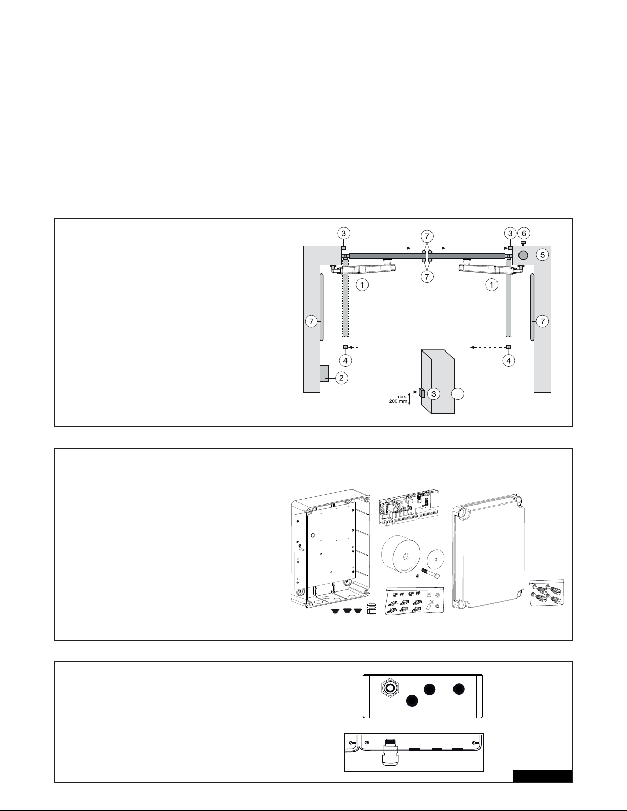
CARACTÉRISTIQUES TECHNIQUES DE LA COMMANDE
Tension : 230 VCA +/- 10% 50-60 Hz
Transformateur : 230/24 VCA, 150 VA
Sortie moteur : 24 VCC
Consommation max. : max. 400 W (en service)
Consommation de veille : max. 4 W (sans accessoires)
Alimentation accessoires : 24 VCC / 600 mA max.
Température de service : -20 ºC ÷ +55 ºC
Mode de fonctionnement : Standard, Automatique
Dimensions : 250 x 75 mm (sans boîtier)
Dimensions boîtier : env. 300 x 220 x 120 mm
Type de protection : IP45
Fusibles : 2 x 2A rapide
Télécommande : max. 170 x code alternant
Fréquences possibles : 433 MHz, 868 MHz
CONFIGURATION TYPIQUE D’UNE INSTALLATION :
1. Commande motorisée
2. Système de commande
3. Barrières photoélectriques (actives quand fermé), hauteur maxi
200 mm première barrière photoélectrique
4. Barrières photoélectriques (actives quand ouvert òu fermé),
hauteur maxi 200 mm deuxième barrière photoélectrique (option)
5. Lampe clignotante (option)
Elle représente un signal optique important pour le mouvement
du portail.
6. Interrupteur à clé ou serrure à code (option)(option)
Est appliqué côté extérieur. Le portail s’ouvre au moyen d’une
clé ou en entrant un code numérique.
7. Le profi lé de contact (option)
Bloque le portail en cas de contact Les profi lés de contact
peuvent être appliqués sur les piliers ou au portail. S’il est
nécessaire, les profi lés de contact doivent être appliqués
jusqu’à une hauteur de 2,5 m.
2/16 fr
POSE DU COFFRET DE COMMANDE
Le système de commande comprend plusieurs composants.
- coffret de commande 1
- couvercle de coffret 1
- système de commande 1
- transformateur 1
- plaque de fond (assemblé) 1
- collier de fi xation grande 1
- collier de fi xation petite 3
- clip de fi xation 6
- vis 3,5mm x 9,5mm 4
- grande rondelle 1
- grande vis 1
- oeillet de câble 1
- écrou M8 2
- rondelle M8 1
- grande vis defermeture 5
PREPARATIFS DU COFFRET DE COMMANDE
Ouvrir les 4 trous au fond du coffret à l’aide d’un
tournevis ou d’un outil similaire. Fixer le grand
passage de câble à gauche, les autres comme dans
l’illustration. L’humidité et l’eau détruisent le système
de commande. Tous les orifi ces et les passages de
câbles doivent être étanches à l’eau. Le coffret de
commande avec la commande motorisée doit être
monté avec les passages de câbles vers le bas
4
+
Page 42
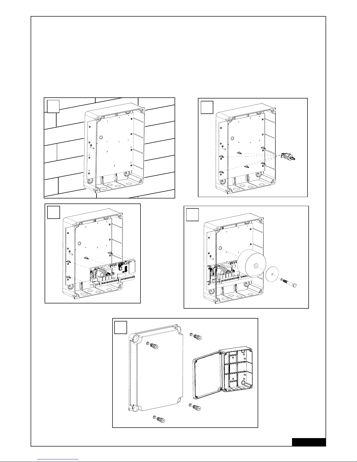
PROCEDE RECOMMANDE
Vissez la partie inférieure du coffret au mur mesurez auparavant les écarts requis et déterminez les trous adaptés (les fi xations ne sont pas
compris) Die Montageplatte ist bereits im Gehäuse montiert. (A)
Appuyez les clips de fi xation sur les trous prevues. (B)
Pesez la commande sur les clips de fi xation. (C)
Visser le transformateur par la grande vis et la grande rondelle sur la plaque de montage. (D)
Placez les 4 grandes vis de fermeture du coffret dans le couvercle du coffret. Vissez 2 des vis de fermeture (à gauche ou à droite) d’env. 2 cm
dans le coffret. Ensuite, le couvercle peut se rabattre sur le côté. (E)
Fermez le coffret en essayant de visser complètement les vis. Si le couvercle ne ferme pas correctement, le coffret ne sera pas bien à plat sur le
mur et il en sera déformé. Ceci doit être corrigé. 1Il est très important que plus tard le coffret puisse fermer en étant étanche à l’eau.
3/16 fr
6x
B
C
D
A
E
Page 43
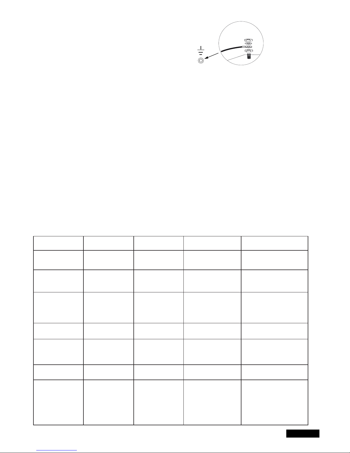
CÂBLAGE DU SYSTÈME DE COMMANDE/ APERÇU :
a. Commencez avec le câble d’alimentation 230 V encore
hors tension du côté gauche du coffret.
b. Fixer l’oillet de câble au conducteur de terre (comme indiqué) .
Raccordez tous les autres câbles au système de commande.
CABLES ET CABLAGE
L’utilisation de câbles blindés du moteur à la commande est recommandée.
Les infl uences magnétiques et inductives ne peuvent pas provoquer de bourdonnements ou nuire au bon fonctionnement de la porte.
Evitez de manière générale :
- d’installer la commande trop loin de la porte.
- de poser ensemble les câbles 230 V et basse tension. Interdit selon les réglementations relatives aux installations électriques.
- de poser les câbles pour les barrières photoélectriques, les interrupteurs, la lampe clignotante et la serrure électrique avec le câble
d’alimentation du moteur.
- de poser les câbles de télécommunication ou pour l’éclairage du jardin avec le câble d’alimentation du moteur.
- les câbles en cuivre rigides sont diffi ciles à poser, surtout lorsque les sections de câbles sont plus importantes. Utilisez des câbles souples.
- utilisez des câbles adaptés à la pose à l’extérieur et en terre, ou passez-les dans des gaines adaptées, ou renseignez-vous auprès
de votre électricien.
Nous recommandons les accessoires suivants :
- Kit LA400-JB40E pour la prolongation des câbles d’une installation. Composé de 12 m de câble, 6 pôles, de couleurs identiques àcelles de
l’entraînement, boîtier de distribution IP65, passe-câbles à vis et matériels de fi xation.
- 041ASWG-0482-50 bobine de 50 m, câble de connexion, 6 pôles pour l’extérieur. Pose possible sans gaine. Couleurs identiques à celles de
l’entraînement.
Dimensions des câbles :
Les dimensions fi gurant dans le tableau sont des valeurs minimales. Des sections plus importantes sont toujours possibles.
- alimentation électrique 230V pour la commande : min. 0,75 mm² 3 pôles
- alimentation électrique 230V pour le transformateur, installé séparément (par ex. Dans le garage) et tension inférieure ou égale à
42V vers la porte. Voir tableau.
- câblage du moteur : 2 câbles min. 1,0 mm², 4 câbles min. 0,75 mm² (ou câbles blindés)
- serrure électrique : voir tableau.
- interrupteurs, barrières photoélectriques, lampe clignotante : voir tableau etc. min.0,5 mm²
4/16 fr
Modèle d’entraînement
LYN, SCS, ART
Câblage du moteur
SUB (entr. encastrable)
Câblage du moteur
Transformateur installé
séparément (dans le
garage) et alimentation
basse tension de la
commande
Serrure électrique (12 V)
Câblage
Antenne externe (retirez
l’antenne d’origine de la
commande)
Interrupteur, lampe
clignotante, etc.
Barrière photoélectrique
Distance
0m - 6m
2 x 1,0mm²
4 x 0,75mm²
2 x 1,0mm²
3 x 0,75mm²
0,75mm²
0,75mm²
Câble coaxial
50 Ohm
0,5mm²
0,5mm²
Distance
6m - 10m
2 x 1,0mm²
4 x 0,75mm²
2 x 1,0mm²
3 x 0,75mm²
0,75mm²
0,75mm²
Câble coaxial
50 Ohm
0,5mm²
0,5mm²
Distance
10m - 12m
Normal
Wiring
Utiliser des câbles
blindés pour les ‚ câbles
de moteur plus petits
1,0mm²
1,0mm²
Câble coaxial
50 Ohm
0,75mm²
0,75mm²
Distance
12m – xx
Max. 15m
Utiliser des câbles blindés pour
les ‚ câbles de moteur plus petits
Utiliser des câbles blindés pour
les ‚ câbles de moteur plus petits
Max. 30m; Min. 1,5mm²
Poids de la porte, 50 % maximum de la puissance du moteur
Max. 30m; Min. 1,5mm²
Câble coaxial
50 Ohm
(max. 25m)
Min. 0,75mm²
Max. 30m
Min. 0,75mm²
Max. 20m
Page 44
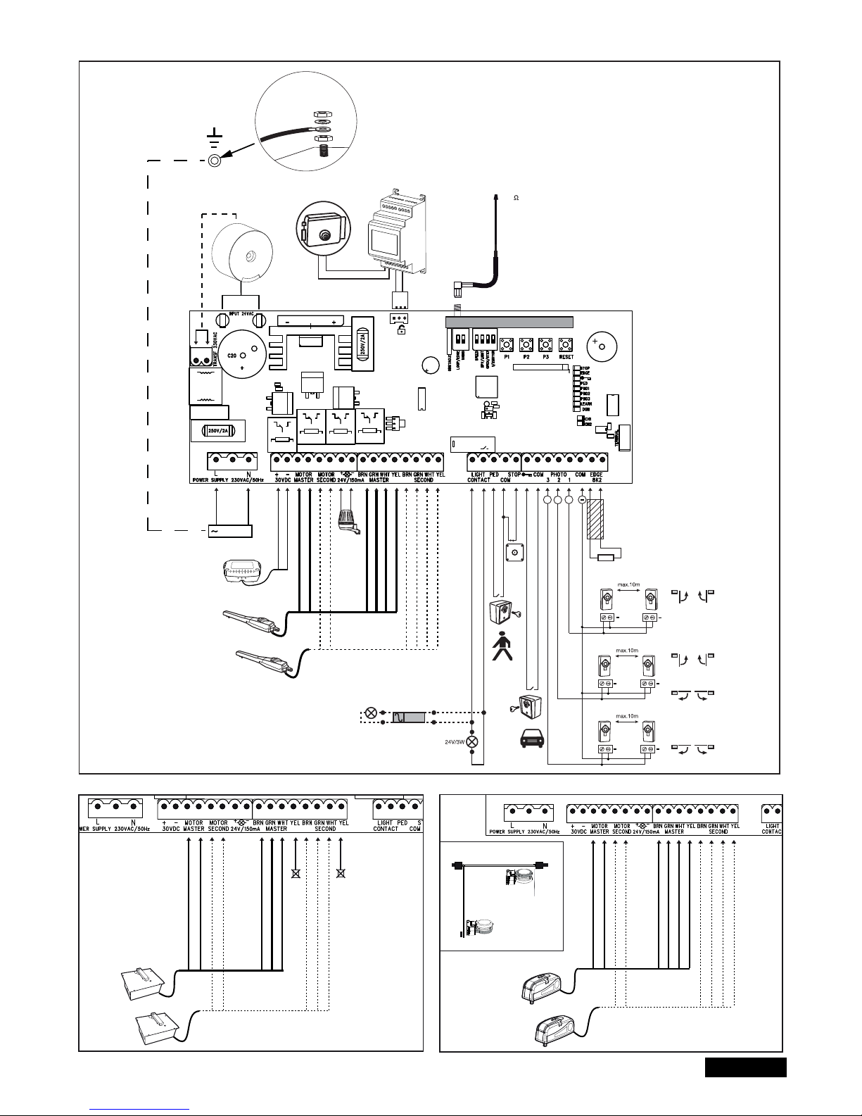
5/16 fr
SCHEMA DES CONNEXIONS
LYN/SCS
230VAC
PE
PE
Model
203285
Ω
8.2
+
+
+
+
+
+
+
Relay
+++
+
-
RED
RED
BLUE
BLUE
Model
CM475
BROWN
GREEN
WHITE
BROWN
GREEN
WHITE
YELLOW
YELLOW
RADIO MODULE
Model
207399
230 VAC
50
RED
RED
BLUE
BLUE
BROWN
GREEN
WHITE
BROWN
GREEN
WHITE
not required
not required
RED
RED
BLUE
BLUE
BROWN
GREEN
WHITE
BROWN
GREEN
WHITE
YELLOW
YELLOW
ART
SUB
Closed position
Open position
batterie
externe
Page 45
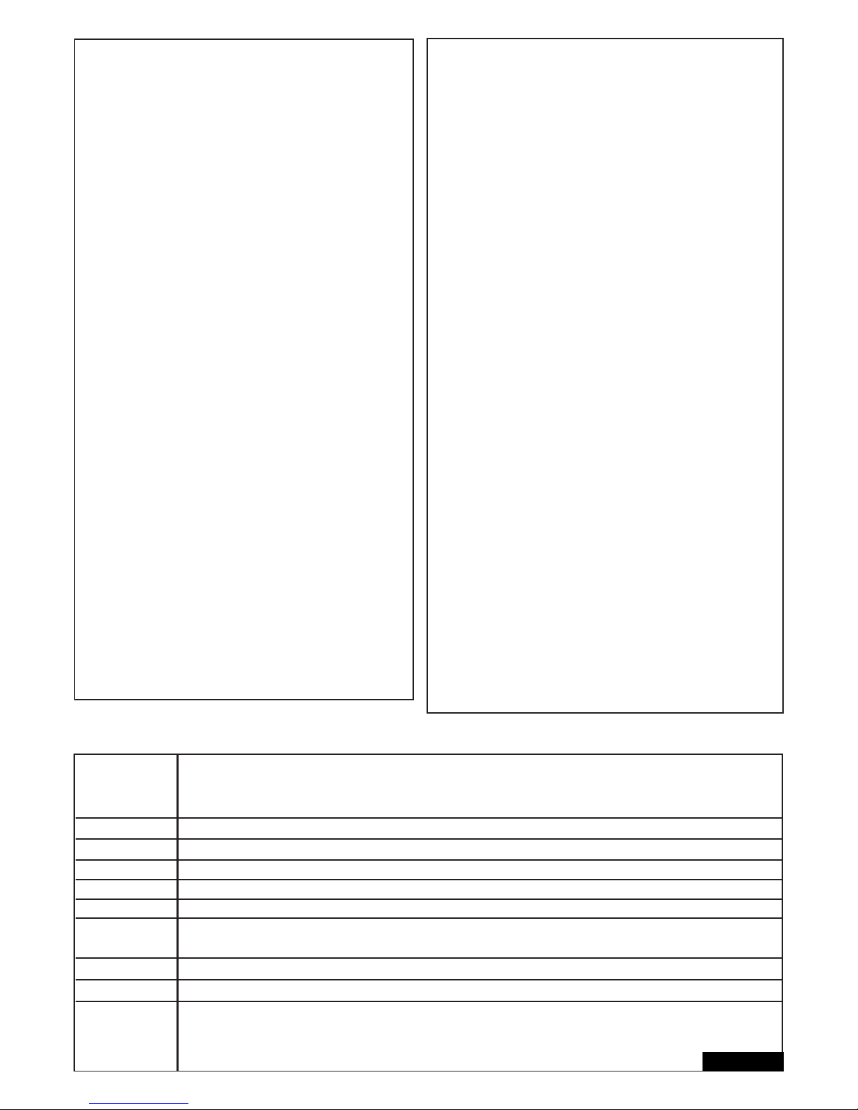
FONCTIONS DES BOUTONS-POUSSOIRS P1, P2, P3 & RESET
P1+P2+P3
P1
P1 + P2
P2 + P3
P1 + P3
P2
P3
DIP „RADIO“ + P1
DIP „RADIO“ + P2
RESET
Mode individuel : les vantaux peuvent être déplacés individuellement. Activer la fonction : Appuyer simultanément sur
P1+P2+P3. La DEL LEARN clignote tant que la fonction est activée. La touche P1 déplace le moteur 1. La touche P2 déplace le
moteur 2. Désactiver la fonction : Attendre 20 secondes ou débrancher la commande. Si les vantaux ferment d’abord, inversez
les câbles rouge et bleu.
Programme automatiquement les postions de fi n de course.
Programme automatiq. les postions de fi n de course (ainsi que des positions supplémentaires, par ex. Soft-Start et Soft-Stop).
Temporisation de la serrure électrique
Réglage de la temporisation de vantail
Fermeture automatique. Pour confi rmer, appuyez sur la touche P2.
Réinitialisation logicielle aux paramètres d’usine. Appuyez pendant 10 secondes sur la touche. La réinitialisation n‘agit pas sur
la mémoire radio (voir Radio).
Programmation des télécommandes pour le canal 1. Signal pour les deux entraînements (vantaux)
Programmation des télécommandes pour le canal 2. Signal pour un entraînement (moteur 1)
Programmation de l‘interface Internet ou de la surveillance de portail : Remarque : Sur cette commande, la touche RESET
n‘entraîne pas de réinitialisation aux paramètres d‘usine. Elle sert uniquement à la programmation de l‘interface Internet ou
de la surveillance du portail. Voir description de la touche P3 pour une réinitialisation aux paramètres d‘usine.
Bouton Fonction
6/16 fr
DESCRIPTION DES BORNES
DESCRIPTION FONCTION
L Raccordement L 230 Volt câble d’alimentation
N Raccordement N 230 Volt câbled’alimentation
30VDC raccordement d’un kit de batterie externe
Motor MASTER Motor 1 (Master, ouvre en premier)
Motor MASTER Motor 2 (Second, ouvre en second)
Pour vérifi er la polarité correcte, voir les sections « Réglage de base
» et « Fonctions des boutons-poussoirs P1, P2, P3 & RESET »
24 V /150 mA lampe clignotante (accessoires)
MASTER Motor1
BRN câble brun
GRN câble vert
WHT câble blanc
YEL câble jaune
SECOND Motor2
BRN câble brun
GRN câble vert
WHT câble blanc
YEL câble jaune
Light Contact Surveillance de porte/éclairage du jardin
PED Connecteur pour l’arrêt d’urgence ou...
COM Pôle négatif
STOP ..coupure stop
“symbole de clé“ interrupteur à clé
COM Pôle négatif
PHOTO 3 barrière photoélectrique 3 (ouvrir)
PHOTO 2 barrière photoélectrique 2 (ferm. + ouv.)
PHOTO 1 barrière photoélectrique 1 (fermer)
COM Pôle négatif
EDGE Le profi lé de contact de 8,2 kOhm
8,2 kOhm
“symbole” Serrure E Entrée Serrure électrique
« entrée de système de commande »
INPUT 24 VAC 24 Volt tension d’entrée du transformateur. Peut
être raccordée avec une quelconque polarité
Transformateur 230 VAC 230 Volt câble d’alimentation vers
transformateur. Peut être raccordé avec une
quelconque polarité.
250 V/2 A fusible 250 V/2 A (2x rapide)
DESCRIPTION DES DEL (DIODES LUMINEUSES)
Description Couleur Fonction
STOP Vert Arrêt d’urgence
ALLUME : Arrêt d’urgence actif
ETEINT : OK (cavalier, si aucun interrupteur
n’est connecté)
EDGE Vert Le profi lé de contact 8.2 kOhm
ALLUME : Activé
ETEINT : OK (cavalier d’une résistance de
8,2 kOhm si aucune profi lé de contact n‘est
connecté)
« symbole de clé“ Rouge interrupteur à clé
ALLUME : interrupteur actionné
ETEINT : interrupteur non actionné
PED Rouge Interrupteur à clé pour 1 vantail
ALLUME : Interrupteur actionné
ETEINT : Interrupteur non actionné
PHO1 Rouge barrière photoélectrique 1 (fermer)
ALLUME : OK (active)
ETEINT : aucune barrière photoélectrique
raccordée
PHO2 Rouge barrière photoélectrique 2 (ferm. + ouv.)
ALLUME : OK (active)
ETEINT : aucune barrière photoélectrique
raccordée
PHO3 Rouge barrière photoélectrique 3 (ouvrir)
ALLUME : OK (active)
ETEINT : aucune barrière photoélectrique
raccordée
LEARN Jaune programme d’apprentissage Statut
ALLUME : Programme d’appr. actif
ETEINT : pas de programme d’appr.
DGN Rouge programme de diagnostique (voir page 15)
CH1 Rouge Programmation des télécommandes pour
le mode à 2 vantaux
ALLUME : Une nouvelle télécommande
peut être programmée
ETEINT : Fonction désactivée
CH2 Rouge Programmation des télécommandes pour
le mode à 1 vantail (voir CH1)
Page 46

7/16 fr
ACCESSOIRES (voir aussi la schema des connexions)
TÈLÈCOMMANDES RADIO (EN OPTION) MODÈLES: TX2EV, TX4EV, TX4UNI (télécommandes),
747EV (serrure à code radio) , 128EV (interrupteur mural à radio 2 fonctions)
LAMPE CLIGNOTANTE (EN OPTION) MODÈLE: FLA24-2, FLA1-LED
Une lampe clignotante peut être raccordée au système de commande (Bornes: 24 VDC / 150 mA). Elle avertit les personnes qui se trouvent
devant le portail en mouvement. La lampe clignotante devrait être placée si possible en hauteur pour être bien visible. Le système de
commande émet un signal constant qui est transformé par la lampe en un clignotement.
INTERRUPTEUR A CLE (EN OPTION) MODÈLE : 100010, 100027, 100034, 100041
L’installation peut être commandée avec un commutateur à clé. (bornes : symbole de clé et COM)
Voir également la description fi gurant sous Commutateurs DIP OPEN/PED.
INTERRUPTEUR D’ARRET D’URGENCE / D’ARRET (EN OPTION) MODÈLE : 600084
Cette sortie sert au raccordement d’un interrupteur d’arrêt d’urgence qui immobilise le portail dans les deux sens.
LE PROFILÉ DE CONTACT (EN OPTION) MODÈLE : 600046, 60003, 600077, 600060
(le commutateur DIP „LOOP/EDGE“ doit être éteint)
Il est mpossible de connecter au système de commande un profi lé de contact (bornes: STOP / 8,2 kOhm) fonctionnant selon le principe 8,2 K
Ohm, à savoir une résistance d’essai de 8,2 K Ohm est fi xée à l’extrémité du profi lé de contact. Elle garantit le contrôle permanent du circuit
électrique. Le système de commande est livré équipé d’une résistance incorporée de 8,2 K Ohm. Plusieures profi lés de contacts sont raccordés
en série.
BARRIÈRES PHOTOÉLECTRIQUES ( EN OPTION) MODELLE 771E, 772E:
Nous recommandons la mise en place d‘une barrière photoélectrique. Utilisez le modèle 771E ou 772E, qui fait également partir du kit d‘accessoires
de sécurité APLUS-EV.
SAFETY ACCESSORY KIT (EN OPTION): APLUS-EV
La commande est déjà équipée d‘une antenne standard. Pour de plus grandes portées, l‘antenne externe comprise dans le kit d‘accessoires APLUS-
EV (ce kit comprend la barrière photoélectrique 771E, le feu clignotant FLA1-LED et l‘antenne externe SWG-ANT-EV) peut être branchée comme
indiqué dans le synoptique de raccordement.
myQ (EN OPTION)
(uniquement avec interface Internet 828EV) :
Permet la commande du portail via l‘Internet ou un Smartphone.
SURVEILLANCE DE PORTAIL (EN OPTION) :
(uniquement avec surveillance de portail 829EV) :
Permet la surveillance visuelle et sonore de la position du portail. Le portail peut aussi être fermé au moyen de cet appareil.
BATTERIE EXTERNE (EN OPTION)
Les connecteurs servent à charger une batterie externe.
En cas de panne de secteur, la batterie assure l’alimentation électrique de l’entraînement. Une batterie entièrement chargée pour fournir
l’énergie nécessaire à plus de 24 heures. Les batteries sont soumises au vieillissement et leur capacité diminue au fi l du temps. Remplacez la
batterie tous les 2-3 ans, en fonction de son utilisation.
SERRURE ELECTRIQUE ( EN OPTION)
Le système de commande est en mesure de faire fonctionner une serrure électrique 12 V. (le mode d’emploi est joint à la serrure électrique).
Pour cela, il faut raccorder au système de commande principal un système de commande auxiliaire destiné à la serrure électrique.
Si la serrure électrique n’ouvre pas en raison d’une pression excessive de la porte, une fonction spéciale peut être programmée : appuyez
pendant env. 5 secondes simultanément sur les touches P2 et P3 et comptez les clics audibles.
1 clic = alimentation électrique de la serrure électrique pendant env. 4 secondes (paramètre d’usine)
2 clics = la porte ferme pendant une seconde puis s’ouvre. De plus, après avoir atteint la position fermée du portail, appuyer brièvement sur
l’actionnement pour favoriser le verrouillage de la serrure électronique. Avis : Pour ce faire, le portail doit être équipé de butées au sol.
SURVEILLANCE DE PORTE OU ECLAIRAGE ( ENOPTION)
Les connexions disposent de deux fonctions, selon l‘ commutateur DIP Light/Spy est allumé ou non. Voir également sous « commutateurs DIP» dans
la présente notice. La sortie ne dispose pas d’alimentation en courant électrique et ne peut être chargée que jusqu’à 24V.
Surveillance de portail / état du portail (Spy)
Une DEL, une ampoule (24V / 3W max.) ou un relais peuvent être raccordés aux bornes pour affi cher l’état du portail.
DEL éteinte = portail fermé
DEL clignote lentement = ouverture du portail
DEL allumée = portail ouvert
DEL clignote rapidement = fermeture du portail
Eclairage de cour / éclairage de 120 secondes
Une lampe (24V / 3W max.) ou un relais peuvent être branchés aux bornes.
Lorsque la commande reçoit un signal pour l’ouverture ou la fermeture, la lampe s’allume pendant 120 secondes, puis s’éteint automatiquement.
ATTENTION: La sortie supportant une charge seulement jusqu‘à 24V maximum, ou un relais doit être intercalé.
Page 47
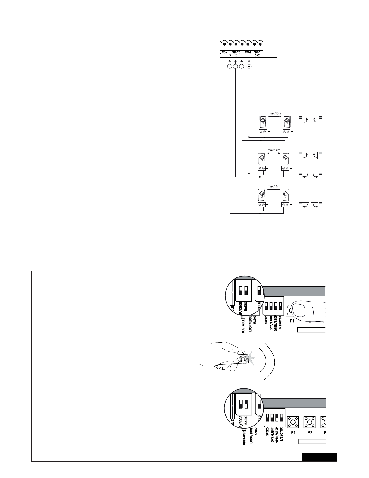
8/16 fr
BARRIERES PHOTOELECTRIQUES (OPTION) 771E, 772E
Les barrières photoélectriques servent à protéger le portail et doivent être utilisées.
L’emplacement de la pose est fonction du modèle de portail. Selon la norme EN12453,
une paire de barrières photoélectriques doit être posée à l’extérieur à une hauteur de
200 mm activée en position « fermeture ». Les barrières photoélectriques comprennent
un émetteur et un récepteur et doivent se faire face l’une et l’autre. La barrière photo- électrique est fi xée au mur au moyen de petites vis et de chevilles. Si la fonction «
fermeture automatique » est possible, il faut alors installer la barrière photoélectrique
Chamberlain – Failsafe. Le système Chamberlain – Failsafe (système à 2 câbles) possède des deux côtés une petite DEL visible de l’extérieur (lumière) pour affi cher le statut
de la barrière photoélectrique.
Programmation de la barrière photoélectrique :
- raccorder barrières photoélectriques correctement
- effectuer une programmation de la course des vantaux de porte.
Suppression d’une barrière photoélectrique de la commande :
une barrière photoélectrique connectée ne peut pas être supprimée sans que la
commande ne bloque le fonctionnement au niveau de la connexion correspondante.
Pour supprimer une barrière photoélectrique du programme de la commande :
- retirer la barrière photoélectrique
- couper brièvement l’alimentation électrique
- effectuer une programmation de la course des vantaux de porte.
Diagnostic à la barrière photoélectrique Chamberlain-Failsafe
DEL constante = OK
DEL clignote = barrière photoélectrique bloque le système de commande
DEL éteinte = hors circuit, mauvais raccordement ou permutation des pôles
Diagnostic au système de commande
DEL éteinte = OK aucune barrière photoélectrique raccordée
DEL clignote = système de commande bloqué
Connecteur 1 & COM
Actif lorsque la porte se ferme (inverse le mouvement de la porte)
Connecteur 2 & COM
Actif lorsque la porte se ferme et s’ouvre
Connecteur 3 & COM
Actif lorsque la porte s’ouvre
(la porte s‘immobilise jusqu‘à ce que l‘obstacle soit écarté du rayon infrarouge,
avant de poursuivre son mouvement)
RADIOCOMMANDE
PROGRAMMER / EFFACER LES TÉLÉCOMMANDES
Le récepteur a 2 canaux CH1 et CH2. L’utilisation d’un ou 2 canaux
permet la mise en marche d’un battant ou des 2 battants du portail. Par
exemple : si CH2 ou P2 reçoit le signal de la télécommande, alors un
seul battant s’ouvrira. Si vous appuyez sur une touche quelconque de la
télécommande avec CH1 ou P1, alors vous ouvrirez les 2 battants du
portail.
PROGRAMMATION
1: Allumez le commutateur DIP „RADIO“.
2: Appuyer brièvement sur le bouton P1 pour CH1 ou sur P2 pour CH2
pour allumer la led de signalisation respective.
3: Appuyer sur le bouton de la télécommande que vous voulez program mer jusqu´à ce que la led de signalisation s’éteigne. Répéter la procé dure pour toutes les télécommandes (85 télécommandes peuvent être
programmées par canal).
Important : Déclenchez le commutateur DIP „RADIO“ toujours après l‘usage. Assurez-vous que le même bouton de la télécommande ne soit pas
programmé sur CH1 et CH2. Cela empêcherait le bon fonctionnement de
l’installation.
EFFACER
- Allumez le commutateur DIP „RADIO“.
- Appuyer sur le bouton P1 usqu´à ce que la led de signalisation au bout
de 10 secondes s’éteigne.
Pour confi rmer, les deux DEL CH1 et CH2 clignotent 8 fois.
- Déclenchez le commutateur DIP „RADIO“
RADIO MODUL
E
ON ON
RADIO MODUL
E
ON ON
RA
ON ON
RA
ON ON
+
+
+
+
+
+
+
+++
Page 48
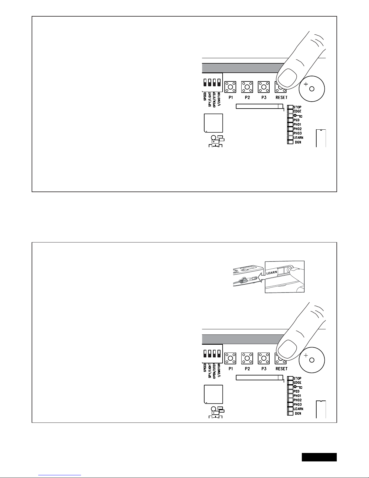
9/16 fr
PROGRAMMATION DE L‘INTERFACE INTERNET myQ
A l‘aide de la touche RESET de la commande
1. Brancher l‘interface Internet Liftmaster et son routeur au câble réseau.
2. Alimenter électriquement l‘interface Internet Liftmaster.
3. Créer un compte en ligne à l‘aide de l‘application Liftmaster myQ pour
Smartphone la plus récente ou sur www.liftmaster.eu.
4. Enregistrer l‘interface Internet Liftmaster.
5. Cliquer sur « Ajouter un nouvel appareil » et suivre les étapes décrites dans
l‘application ou sur le site Internet.
6. Remarque : Si vous appuyez sur la touche RESET, vous entendrez un signal
sonore et les DEL CH1 et CH2 s‘allument. Puis, après la synchronisation,
elles clignotent trois fois et s‘éteignent.
7. L‘application indique si la programmation a réussi et vous invitera à attribuer
un nom au portail.
PROGRAMMATION DE LA SURVEILLANCE DE PORTAIL
A l‘aide de la touche RESET de la commande
1. Alimenter électriquement la surveillance de portail et la positionner de telle
sorte dans la maison qu‘elle soit bien visible. Si le lieu d‘installation est trop
loin du portail, la connexion peut être faible ou souvent interrompue. Choisis sez un endroit plus approprié pour l‘installer.
2. Appuyez brièvement sur la touche « LEARN » au dos de la surveillance de
portail. Les DEL rouge et verte clignotent en alternant. Dans un délai de 60
secondes, appuyer brièvement sur la touche RESET de la commande. Les
DEL rouge et verte s‘allument brièvement pour confi rmer la programmation.
Supprimer la surveillance de portail
appuyer pendant au moins 10 secondes sur la touche « LEARN » au dos de la
surveillance de portail.
Un bref signal sonore confi rme le succès de la suppression.
ADIO MODULE
ADIO MODULE
Page 49
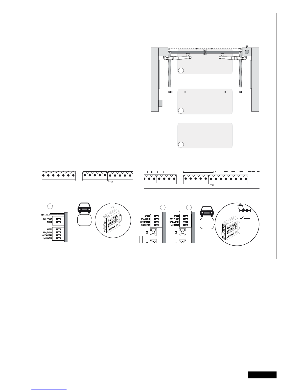
DETECTEURS DE BOUCLES
(le commutateur DIP LOOP/EDGE doit être allumé)
Les détecteurs de boucles réagissent au métal et sont souvent
utilisés pour la détection de voitures et de poids-lourds, mais ne
réagissent pas aux motos et aux piétons.
Boucle de sortie A
La boucle de sortie se trouve derrière la porte et ouvre la porte
lorsqu’elle est fermée, la maintient ouverte ou l’ouvre une nouvelle
fois. Les commutateurs DIP OPEN/STEP et LOOP/EDGE doivent être
allumé. Les barrières photoélectriques doivent être connectées et la
fonction „Fermeture automatique“ doit être activée.
Détecteur de boucle de sécurité et détecteur de
boucle dans la zone de pivotement de la porte B,C
Les détecteurs de boucles servent à la détection des véhicules
(voitures et poids-lourds ; en tant que mesure de sécurité unique,
ils ne sont pas admissibles puisqu’ils ne détectent pas les
personnes). Le module d’analyse des détecteurs de boucles est
raccordé en tant que transmetteur de signaux aux bornes de la
baguette de contact 8.2kOhm. Si vous souhaitez aussi utiliser des
baguettes de contact :
vérifi ez avant l’installation quel est le mode de fonctionnement
adapté à votre installation.
Détecteur de boucle de sécurité
=> Le commutateur DIP OPEN/STEP doit être allumé.
Détecteur de boucle dans le zone de pivotement de la porte
=> Déclancher le commutateur DIP OPEN/STEP
Vous pouvez vous renseigner auprès de notre service sur d’autres
options concernant les déteteurs de boucles.
10/16 fr
RN WHT YEL
ASTER
BRN GRN WHT YEL
SECOND
COM
PHOTO
3 2 1
C
LIGHT
CONTACT
PED
COM
STOP
NO
Model
203292
Model
203292
RN WHT YEL
ASTER
BRN GRN WHT YEL
SECOND
COM
PHOTO
3 2 1
COM EDGE
8.2KΩ
LIGHT
CONTACT
PED
COM
STOP
NO
COM
NC
A
B
C
A
B C
RADIO
ON ON
RADIO
MOD
ON
RADIO
MOD
ON
Page 50
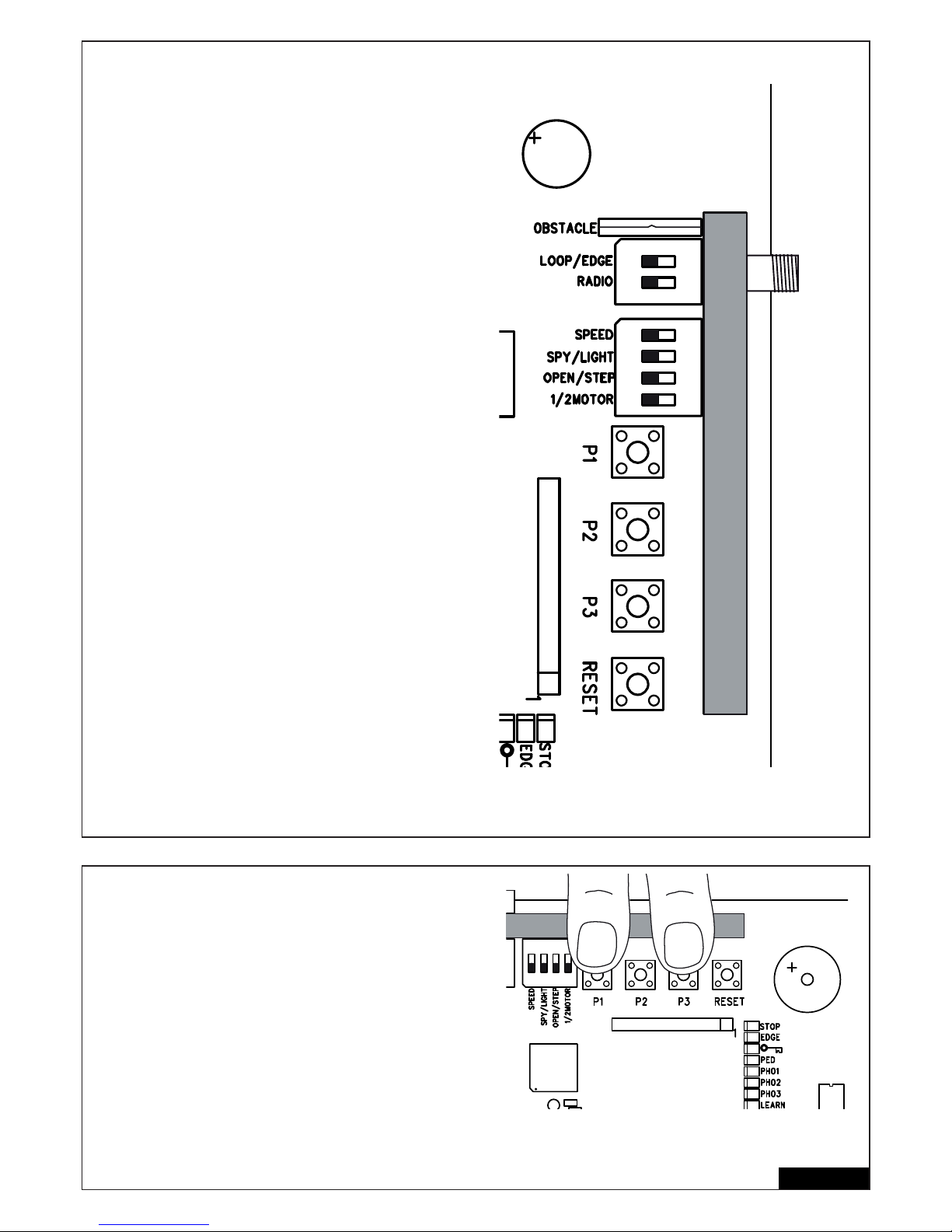
Commutateurs DIP
MOTEUR 1/2
Sélectionne si 1 ou 2 moteurs sont raccordés à la commande.
ETEINT : 2 moteurs sont connectés
ALLUME : 1 moteur est connecté
OPEN/STEP
Modifi e la programmation et la réaction de la commande aux signaux.
Pour l’utilisation des détecteurs de boucles, veuillez vous reporter
d’abord à la section « Détecteurs de boucles ».
Mode pas-à-pas : Le premier signal ouvre la porte, le second
l’immobilise, le troisième signal la ferme, le quatrième l’immobilise, le
cinquième l’ouvre, etc.
Mode d’ouverture : la porte ne réagit pas aux signaux de commande
tant qu’il s’ouvre et n’a pas atteint la position OUVERTE.
ETEINT : Mode pas-à-pas
ALLUME : Mode d’ouverture
LIGHT/SPY
N’enfi cher que si la fonction est nécessaire, sinon laisser libre.
ETEINT : LIGHT
ALLUME : SPY
OBSTACLE
Equipé en usine d’un pontage à fi l fi xe. Le sectionnement augmente la
puissance de travail à la commande. ATTENTION: Si le pontage à fi l
est sectionné, le portail doit être sécurisé avec des installations de
sécurité supplémentaires (réglette de contact, etc.).
LOOP/EDGE
Sélectionnez la fonction souhaitée
ETEINT : Baguette de contact
ALLUME : Détecteur de boucle
SPEED
Sélectionnez le type de moteur que vous souhaitez utiliser.
ETEINT : ART
ALLUME : LYN, SCS, ART, SUB
RADIO
Le commutateur DIP « RADIO » est nécessaire pour la programmation
des télécommandes. Le processus de programmation fi gure dans la
section correspondante de la présente notice.
ETEINT : Aucune programmation n’est possible
ALLUME : La programmation est possible
IMPORTANT : Toujours déclencher le commutateur DIP « RADIO »
lorsqu’il n’est pas utilisé.
TEMPORISATION DE VANTAIL
La temporisation de vantail est nécessaire pour l’ouverture et la
fermeture correcte des vantaux. Une temporisation de vantail plus
longue peut être nécessaire lorsque les conditions d’installation ou les
longueurs de vantail sont différentes.
Appuyez et maintenez les touches P1 et P3 simultanément pendant
env. 5 secondes et comptez le nombre de clics audibles. Les clics sont
générés par un relais (relais de lumière).
1 clic = temporisation courte d’env. 4÷8 secondes (paramétrage d’usine)
2 clics = temporisation moyenne d’env. 8÷12 secondes
3 clics = temporisation longue d’env. 12÷16 secondes
4 clics = temporisation intégrale ; le vantail 1 ne ferme que lorsque
le vantail 2 est entièrement fermé.
La temporisation à l’ouverture est toujours d‘env. 3÷5.
5 clics = aucune temporisation ;
les deux vantaux ouvrent et ferment simultanément
REMARQUE : la programmation (modifi cation) de la course réinitialise
la temporisation de vantail au paramétrage d’usine.
11/16 fr
RADIO MODULE
RADIO MODULE
ON ON
Page 51
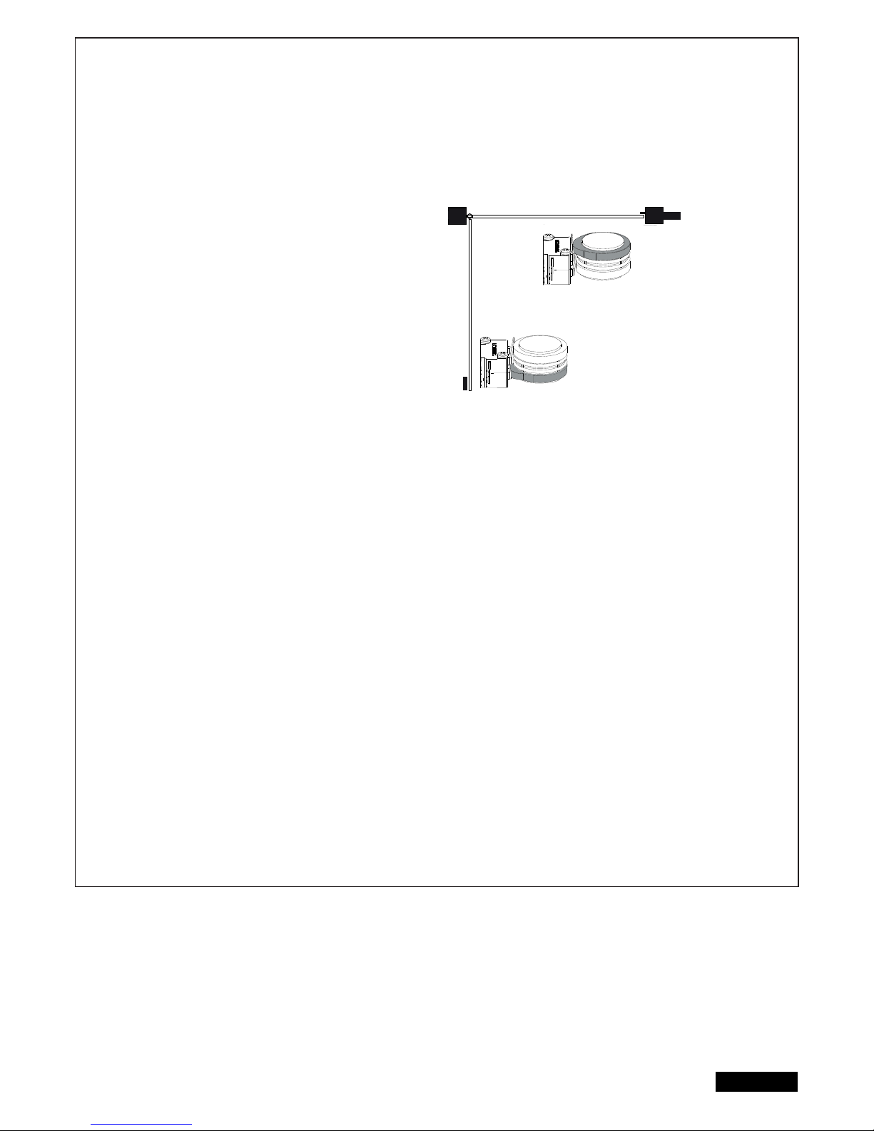
12/16 fr
PREMIERE MISE EN SERVICE/ REGLAGE DE BASE
Procédez exactement point par point. En cas de doute, recommencez depuis le début. Prenez votre temps pour effectuer ces
réglages.
1. Est-ce que tous les éléments sont raccordés pour que le fonctionnement se fasse correctement ? Moteurs, barrières photoélectriques, profi lé de
contact de sécurité, interrupteur d’arrêt.
2. Assurez-vous que personne ne séjourne au niveau du portail ou puisse y séjourner.
3. Fermez le portail et accrochez-y les moteurs. Fixez les moteurs avec le boulon à goupille et tournez le levier de déverrouillage en direction du
pilier du portail. Les commandes motorisées sont verrouillées.
ART :
- pour le succès de la programmation de la course, les points de
référence doivent être réglés. A cet effet, les cames sous le carter de
l’ART doivent être réglées correctement. La came supérieure doit
déclencher le microrupteur en premier, puis la came inférieure. Les
microrupteurs ne doivent pas se déclencher simultanément ou lorsque
la porte a atteint ses positions de fi ns de course. Ecartez les cames au
moyen d’une pince ou d’un grand tournevis plat.
- déverrouillez la porte pour ces réglages.
- contrôlez ou corrigez les positions des cames de commutation comme
indiqué dans la notice pour les commandes porte OUVERTE et porte
FERMEE.
- réglage des commutateurs DIP en cas d’utilisation de l’ART :
Déclencher le commutateur DIP « SPEED ».
L’ART ne fonctionnera pas si le commutateur DIP « SPEED » set allumé.
SUB (entraînement encastrable) :
- Réglage des commutateurs DIP : le commutateur DIP « SPEED » est allumé pour un mouvement plus rapide de la porte. Il ne l’est pas si la porte
est très lourde ou que le fonctionnement doit être très sûr. Peut être modifi é à tout moment après l’installation.
Entraînements LYN / SCS :
Réglage des commutateurs DIP : le commutateur DIP « SPEED » est allumé pour un mouvement plus rapide de la porte. Il ne l’est pas si la porte
est très lourde ou que le fonctionnement doit être très sûr. Peut être modifi é à tout moment après l’installation.
Raccordez maintenant le système de commande au secteur.
REGLAGE DE BASE :
1. Appuyez simultanément sur les boutons P1, P2 et P3 durant 2 à 3 secondes jusqu’à ce que la DEL jaune clignote.
2. Observez en même temps le portail. Appuyez sur la touche P1 et maintenez-la appuyée durant 1 à 2 secondes. Le portail avec Moteur 1
doit se déplacer en direction AUF (OUVERT). (ne pas ouvrir complètement le portail, procéder par petits déplacements)
Si le moteur 1 ferme le portail au lieu de l’ouvrir, il est mal raccordé et il faut permuter les câbles rouge et bleu au moteur
(Attention : mettre auparavant le système de commande hors circuit !).
Remarque : Fonction générale – si vous relâchez le bouton, le portail s’arrête immédiatement. En appuyant une nouvelle fois, il se
déplace dans le sens inverse jusqu’à ce que vous relâchiez à nouveau le bouton, etc.
3. Appuyez sur la touche P2 et maintenez-la appuyée durant 1 à 2 secondes. Le portail avec Moteur 2 doit se déplacer en direction
AUF (OUVERT). (ne pas ouvrir complètement le portail, procéder par petits déplacements) Si le moteur 2 ferme le portail au lieu
de l’ouvrir, il est mal raccordé et il faut permuter les câbles rouge et bleu au moteur (Attention : mettre auparavant le système de
commande hors circuit !).
Remarque : Le système de commande demeure 20 secondes dans ce programme de réglage manuel. Recommencez le cas
échéant depuis le début en appuyant simultanément sur les touches P1/P2/P3.
Vérifi ez :
1. Uniquement sur SCS : Lorsque le vantail s’ouvre, le « taquet » avant du moteur ne doit PAS toucher la porte (buter ou frotter contre elle).
Interrompre l’ouverture à plusieurs reprises pour contrôler ! En cas de contact, la cote A/B doit être contrôlé et éventuellement la ferrure de la
porte rehaussée pour obtenir un plus grand écart.
2. Ouvrir les deux vantaux complètement. Ne pas ouvrir de trop ! Si aucune butée OUVERT n’existe, marquez le point d’ouverture
maximale.
3. Uniquement sur SUB (entraînement encastrable) : Ajustez à présent les butées de fi n de course mécaniques dans le boîtier.
Patientez jusqu’à ce que la DEL LEARN s’éteigne d’elle-même (20 secondes après avoir appuyé sur la touche).
Closed position
Open position
portail fermé
portail ouvert
Page 52

13/16 fr
PROGRAMMATION DES PARCOURS SIMPLE I
Remarque : Les butées de fi n de course dans FERME et OUVERT doivent être existantes.
1. Les battants doivent être fermés.
2. Appuyez sur le bouton P1 tant que la battant / moteur 1 commence à s’ouvrir. (DEL « LEARN » clignote)
Le programme automatique commence (déplacement lent) :
Le battant 1 se déplace jusqu’au butoir AUF (OUVERT).
Le battant 2 se déplace jusqu’au butoir AUF (OUVERT).
Ensuite, le battant 2 se déplace jusqu’au butoir ZU (FERME) et ernsuite le battant 1 se déplace jusqu’au butoir ZU (FERME).
Quand la DEL « LEARN » s’éteint, la programmation est terminée.
Remarque : Si les battants se ferment au lieu de s’ouvrir, les moteurs sont mal raccordés. Permutez rouge et bleu.
PROGRAMMATION DES PARCOURS SIMPLE II
Remarque : S’il n’y a aucun butoir en direction AUF (OUVERT), le battant devrait s’arrêter à un angle d’ouverture d’env. 90°.)
1. Les battants doivent être fermés.
2. Appuyez sur le bouton P1 tant que la battant / moteur 1 commence à s’ouvrir.
3. Appuyez une fois sur la touche P1 « tief drücken » (appuyer à fond) lorsque le battant / moteur 1 a atteint la position Portail AUF
(OUVERT). Le battant 2 démarre.
4. Appuyez une fois sur la touche P1 « tief drücken » (appuyer à fond) lorsque le battant / moteur 2 a atteint la position Portail AUF
(OUVERT). Le battant 2 se referme ensuite automatiquement. Puis le battant 1 ferme automatiquement.
5. La commande motorisée « apprend » automatiquement la position Portail ZU (FERME).
Sur demande, vous pouvez aussi programmer un point individuel dans Portail ZU (FERME).
Appuyez sur la touche P1 « tief drücken » (appuyer à fond) puis à la position souhaitée Portail ZU (FERME) pour le battant
respectif. Quand la DEL « LEARN » s’éteint, la programmation est terminée.
PROGRAMMATION DU PARCOURS « ADVANCED » (INDIVIDUEL)
Remarque : Dans ce programme, la touche P1 doit être appuyée à neuf reprises.
Une position (temps) est enregistrée à chaque pression de touche. Cela rend possible d’enregistrer l’arrêt progressif (course lente) pour s’adapter
individuellement au portail ou à l’application. Des phases d’arrêt progressif longues ou courtes sont possibles.
1. Les battants doivent être fermés.
2. Appuyez durant environ 5 à 6 secondes simultanément sur P1 et P2 jusqu‘à ce que le battant 1 démarre (s‘ouvre). Relâchez les touches !
3. Réappuyez sur P1 ; l’arrêt progressif en direction AUF (OUVERT) pour le battant 1 commence à partir de cette position.
4. Réappuyez sur P1 ; butoir AUF (OUVERT) atteint. Le battant 2 démarre maintenant automatiquement.
5. Réappuyez sur P1 ; l’arrêt progressif en direction AUF (OUVERT) pour le battant 2 commence à partir de cette position.
6. Réappuyez sur P1 ; butoir AUF (OUVERT) atteint. Le battant 2 démarre maintenant automatiquement et se ferme.
7. Réappuyez sur P1 ; l’arrêt progressif en direction ZU (FERME) pour le portail 2 commence à partir de cette position.
8. Réappuyez sur P1 ; butoir en direction ZU (FERME) atteint. Le battant 1 démarre maintenant automatiquement.
9. Réappuyez sur P1 ; l’arrêt progressif en direction ZU (FERME) pour le battant 1 commence à partir de cette position.
10. Réappuyez sur P1 ; butoir ZU (FERME) atteint. -> terminé !
Remarque : Si un battant atteint un butoir et que la touche L1 n’est PAS appuyée, la commande motorisée se déplace sur la butée et « apprend »
cette position automatiquement.
Page 53
14/16 fr
FIN DE L’INSTALLATION / DE LA PROGRAMMATION:
Si le parcours est programmé, les émetteurs portatifs peuvent être également programmés (Cf. PROGRAMMATION / EFFACEMENT
DES EMETTEURS PORTATIFS).
1. Laissez maintenant le portail parcourir 2 cycles complets en appuyant sur l’émetteur manuel ou sur un bouton raccordé et observez
le déroulement. Refermez le portail SANS faire d‘autres réglages.
2. Si tous les réglages sont faits, vérifi ez la fonction des barrières photoélectriques, boutons, lampe clignotante, émetteur portatif,
accessoires, etc.
3. Montrez à toutes les personnes qui doivent être familiarisées avec le maniement du portail les différents mouvements du portail, les
fonctions de sécurité, le déverrouillage du portail et l’actionnement manuel.
Fermeture automatique du portail
Remarque : uniquement possible avec barrière photoélectrique raccordé et fonctionnant (1+COM). Il est possible de choisir un temps
de fermeture automatique situé entre 2 et 120 secondes.
Réglage
1. Appuyez sur P2 et maintenez appuyée jusqu’à ce que la DEL jaune commence à clignoter.
2. Lorsque la DEL jaune clignote, décomptez le temps d’ouverture qui doit être programmé.
3. A l’achèvement du temps souhaité, appuyez à nouveau sur P2. -> terminé !
Mise hors circuit
1. Appuyez sur P2 et maintenez appuyée jusqu’à ce que la DEL jaune commence à clignoter.
2. Appuyez sur P3. La DEL jaune s’éteint. -> terminé !
FORCE DE FONCTIONNEMENT DE LA COMMANDE
MOTORISEE
La force de fonctionnement de la commande motorisée se règle automa tiquement pendant la programmation du parcours. Une modifi cation (auto-
matique) n’est possible qu’avec une nouvelle programmation du parcours.
Si le portail se coince du fait des intempéries ou suite à des modifi cations
effectuées sur l’installation du portail (par ex. par la rouille ou un
graissage insuffi sant), il faut réparer le cas échéant.
Le système de commande satisfait les normes EN les plus
récentes. Une de ces normes prescrit que les forces de
fermeture au bord du portail ne doivent pas dépasser 400 N (40 kg)
dans les derniers 500 mm avant la fermeture du portail. Au-dessus
de 500 mm, la force maximale exercée au bord du portail peut
s’élever à 1400 N (140 kg). Si ceci ne peut être garanti, il faut
absolument appliquer un profi lé de contact évtl. jusqu’à une hauteur
de 2,5 m au portail ou au pilier opposé (EN12453).
ELIMINATION
L’emballage se compose de matières respectueuses de l’environnement. Il peut être éliminé dans les conteneurs de recyclage locaux.
Conformément à la directive européenne 2002/96/CE relative aux appareils électriques usagés, cet appareil doit être éliminé en fi n de cycle
de vie conformément aux réglementations, afi n d’assurer la revalorisation des matières utilisées.
Votre administration communale ou urbaine se fera un plaisir de vous renseigner au sujet des possibilités d’élimination.
ELIMINATION DES PILES
Les piles et piles rechargeables ne doivent pas être éliminées par les ordures.
Vous pouvez aussi remettre vos piles et piles rechargeables usagées gratuitement
à un commerçant ou un point de collecte communal à proximité de chez vous.
Les piles et piles rechargeables sont identifi és par une poubelle rayée
d’une croix, ainsi que par le symbole chimique du polluant, c‘est-à-dire
« Cd » pour Cadmium, « Hg » pour Mercure et« Pb » pour Plomb.
12VDC
Pb Cd Hg
Page 54

15/16 fr
INDICATION DE LA DEL DE DIAGNOSTIC
La DEL de diagnostic montre le premier dysfonctionnement survenu. Si d’autres dysfonctionnements sont actifs, ils ne sont éventuellement pas
indiqués.
Indication
1 clignotement
2 clignotements
3 clignotements
4 clignotements
5 clignotements
6 clignotements
7 clignotements
8 clignotements
9 clignotements
10 clignotements
11 clignotements
12 clignotements
13 clignotements
14 clignotements
15 clignotements
Descriptif
Commande motorisée 1 Défaut de contact d’un câble de
commande vers le système de commande
Comme 1 clignotement pour commande motorisée 2
Les points de fi n de course de la commande motorisée 2
ne sont pas acceptés.
A: Après ou durant le parcours d’apprentissage : la
commande motorisée 1 ne s’est pas ouverte
suffi samment
B: défaut de contact d’un câble de commande vers le
système de commande. Le câble jaune ou blanc n’a pas
de contact ou un mauvais contact.
Les points de fi n de course de la commande motorisée 1
ne sont pas acceptés.
Le parcours n’est pas programmé dans le système de
commande.
La force requise pour déplacer le battant est trop élevée.
A: Le portail est défectueux
B: Le portail est grippé
C: Le portail s’arrête quand le vent souffl e.
La barrière photoélectrique 1 bloque la fonction
A: Un objet bloque la barrière photoélectrique
B: L’orientation des lentilles l’une par rapport à l’autre est
imprécise.
C: L’alimentation électrique des barrières
photoélectriques est insuffi sante
La barrière photoélectrique 2 bloque la fonction
La barrière photoélectrique 3 bloque la fonction
L’interrupteur d’arrêt d’urgence bloque l’installation
Le Profi lé de contact bloque l’installation
A: Un objet s’appuie sur le profi lé de contact
B: Profi lé de contact défectueux
C: Alimentation électrique trop faible ou rupture du câble
d’alimentation.
Alimentation électrique du système de commande trop faible
A: Câble d’alimentation 230 V défectueux ou mauvais
contacts
B: Rupture du câble d’alimentation (câbles en cuivre
rigides)
C: La batterie fournie en accessoire pour se substituer
en cas de panne de courant est déchargée.
Défaut d’EEPROM
Echec du « démarrage » du système de commande
Uniquement sur LYN/SCS :
moteur encore déverrouillé
Défaillance d’un relais ou d’un autre sous-ensemble
électronique important
A : Surtension
B : Erreur de câblage
D : Forte humidité dans la barrière photoélectrique
(installation défectueuse)
E : Une barrière photoélectrique a été connectée
auparavant, mais n’a pas été retirée (débranchée)
Solution
Le câble vert ou blanc n’a pas de contact ou un mauvais contact.
Vérifi er avec soin les connexions. Veiller aux longueurs de câbles.
Cf. 1 clignotement
Sur A : Ouvrir plus le portail durant le parcours d’apprentissage.
Plus de 50 % du parcours maximum.
Sur B : Vérifi er avec soin les connexions. Veiller aux longueurs de
câbles.
Cf. 3 clignotements
Répéter le parcours d’apprentissage des points de fi n de course
A: Réparer le portail
B: Vérifi er la bonne manoeuvrabilité du portail
C: Ne pas faire fonctionner le portail par vent fort
D : Répéter le parcours d’apprentissage des points de fi n de cour-
se afi n de pouvoir reprogrammer la force requise.
A: Retirer
B: Vérifi er
C: Vérifi er les sections transversales de câbles et les raccorde-
ments
Cf. 7 clignotements
Cf. 7 clignotements
A: Contrôler le câblage
B: Contrôler le réglage de base du système de commande (DIPs)
A: Retirer
B: Contrôler le câblage Contrôler la résistance 8,2 K Ohm.
C: Contrôler le réglage de base du système de commande (DIPs)
A: Contrôler les raccordements
B: Contrôle (technicien)
C: Recharger la batterie durant 24 heures.
Remplacer le système de commande
Verrouiller le moteur
Remplacer la commande
Vérifi er le câblage
Réeffectuer l’apprentissage de la course à partir de la position
porte
complètement fermée
Page 55

16/16 fr
QUESTIONS FREQUEMMENT POSEES
Pas de réaction lors de l’actionnement de P1, P2, P3 Le commutateur DIP „RADIO“ doit être
déclenché
La commande motorisée ne réagit pas, aucune Evtl. panne de courant 1. Contrôler les conducteurs et le neutre
DEL n’est allumée 2. Contrôler les fusibles du domicile
Aussitôt après que le portail s’est mis en
mouvement, il s’arrête et revient dans sa
position de départ
Le portail s’ouvre mais ne se ferme pas
La « fermeture automatique » ne fonctionne pas
Le système de commande ne fonctionne plus
avec l’émetteur portatif, mais uniquement avec
l’interrupteur quand on appuie sur une touche en
la maintenant appuyée.
La commande motorisée ne réagit pas du tout
bien que le système de commande soit raccordé. (les DEL sont allumés)
Le système de commande ne fonctionne pas
avec l’émetteur portatif
Le système de commande ne fonctionne pas
Les battants ne s’ouvent pas entièrement
Le pilier du portail est trop épais, si bien que les
cotes A+B ne peuvent pas être respectées.
La course ne peut pas être enregistrée.
L’entraînement fonctionne brièvement en
marche lente.
Obstacle dans la zone du portail ou portail
grippé
(Faire intervenir un spécialiste)
photcellule bloque
Une photcellule de sécurité, un profi lé de
contact ou l’arrêt bloque le système de
commande. Une seule photocellule pour
(OUVERT) est raccordée.
1. Emetteur portatif non programmé
2. Les DEL signalent un défaut
3. Les photcellules sont mal raccordées
4. La borne des moteurs n’est évtl. pas
correctement enfi chée
1. Emetteur portatif non programmé
2. Une photcellule bloque
3. Commutateur DIP “RADIO”
Aucun parcours programmé
1. Force trop faible pour la charge élevée
due à l’action du vent (portails pleins)
2. Portail grippé/lourd
Evider le pilier ou décaler le portail
1. Le réglage des DIPs n’est pas correct
2. Le câblage du moteur est erroné ou un
câble est défectueux
3. Voir DEL de diagnostic
4. Bourdonnement dans le câblage
5. La porte ne se déplace que pendant 1
seconde lors de la programmation, puis
s’immobilise sans inverser le mouvement.
6. Uniquement sur ART : le réglage des
points de référence n’est pas correct
7. Uniquement sur ART : le moteur est
encore déverrouillé
Panne de secteur.
Contrôler l’absence d’obstacles dans la zone
du la portail
Contrôler les photcellules
Reprogrammer la course.
Contrôler le fonctionnement et le raccordement
Ne fonctionne qu’avec la photocellule à 2
câbles 771E(ML) ou 772E(ML).
Il faut au moins raccorder une photcellule
active dans (FERME) ou (OUVERT).
1. Programmer l’émetteur portatif
2. Cf. descriptif « Diagnostic » DEL
3. Vérifi er le raccordement / laprogrammation
des photcellules
4. Vérifi er la borne et les raccordements
1. Programmer l’émetteur portatif
2. Contrôler les photcellules
3. Déclencher le commutateur DIP
Programmer le parcours. Cf. Première mise
en service. Cf. Diagnostic DEL.
1. Améliorer la manoeuvrabilité
2. Reprogrammer le système de commande
1. Consultez dans la notice la section « Moteur 1/2 »
2. Si le moteur tourne, vérifi ez les conducteurs
marron, vert, blanc et jaune. Essayez un autre câble
pour exclure toute défaillance du câble posé en terre
ou branchez à des fi ns d’essai le câble sortant du
moteur directement à la commande.
3. Contrôle du DEL de diagnostic pour déterminer
le dysfonctionnement.
4. Voir solution 2. Si nécessaire, remplacer le câble.
Voir également le point « Dimensions des câbles »
5. Alimentation électrique insuffi sante ou câblage
erroné. Voir solution 2.
6. Réglez correctement les cames du moteur.
Voir notice ART
7. Verrouiller l’entraînement. Voir notice ART
Processus normal. Après une panne de secteur,
l‘entraînement exécute un test de fonctionnement.
En fonction du modèle, celui-ci dure de quelques
secondes à un cycle complet. N’immobilisez pas
l’entraînement avec la télécommande ou un interrupteur pendant l’exécution du test de fonctionnement,
au risque de déplacer les points de fi n de course.
Dans ce cas, la course doit être reprogrammée au
moyen de la touche P1.Evitez les pannes de secteur
inutiles.
La portée de l’émetteur est trop faible Il est recommandé d’installer une antenne extérieure car dans la plupart des cas le système de
commande avec la petite antenne à câble se trouve derrière le pilier ou à proximité du sol. La
position optimale de l’antenne est toujours le plus haut possible. Chamberlain propose en acces soire une antenne avec un kit de montage.
Le portail doit suivre une pente Non recommandé ! Modifi er le portail ! Le portail peut bouger d’une manière incontrôlée
(danger) lorsque la commande motorisée est déverrouillée. En direction de la pente, une plus
grande force est requise ; dans le sens contraire la commande motorisée a trop de force.
Page 56

TOPIC PAGE
SAFETY RULES . . . . . . . . . . . . . . . . . . . . . . . . . . . . . . . . . . . . . . . . . . . . . . . . . . . . . . . . . . . . . . . . . . . . . . . . . . . . . . . . . . . . . .1
TECHNICAL DATA . . . . . . . . . . . . . . . . . . . . . . . . . . . . . . . . . . . . . . . . . . . . . . . . . . . . . . . . . . . . . . . . . . . . . . . . . . . . . . . . . . . .2
TYPICAL CONFIGURATION OF A UNIT . . . . . . . . . . . . . . . . . . . . . . . . . . . . . . . . . . . . . . . . . . . . . . . . . . . . . . . . . . . . . . . . . . .2
CONTROL BOX . . . . . . . . . . . . . . . . . . . . . . . . . . . . . . . . . . . . . . . . . . . . . . . . . . . . . . . . . . . . . . . . . . . . . . . . . . . . . . . . . . . . . .2
PREPARATION . . . . . . . . . . . . . . . . . . . . . . . . . . . . . . . . . . . . . . . . . . . . . . . . . . . . . . . . . . . . . . . . . . . . . . . . . . . . . . . . . . . . . . .2
RECOMMENDED PROCEDURE . . . . . . . . . . . . . . . . . . . . . . . . . . . . . . . . . . . . . . . . . . . . . . . . . . . . . . . . . . . . . . . . . . . . . . . . .3
WIRING OF CONTROL / SUMMARY / CABLES AND WIRING . . . . . . . . . . . . . . . . . . . . . . . . . . . . . . . . . . . . . . . . . . . . . . . . .4
WIRING DIAGRAMM . . . . . . . . . . . . . . . . . . . . . . . . . . . . . . . . . . . . . . . . . . . . . . . . . . . . . . . . . . . . . . . . . . . . . . . . . . . . . . . . . .5
DESCRIPTION / FUNCTION OF TERMINALS . . . . . . . . . . . . . . . . . . . . . . . . . . . . . . . . . . . . . . . . . . . . . . . . . . . . . . . . . . . . . . 6
DESCRIPTION OF LEDS . . . . . . . . . . . . . . . . . . . . . . . . . . . . . . . . . . . . . . . . . . . . . . . . . . . . . . . . . . . . . . . . . . . . . . . . . . . . . . .6
FUNTIONALITY OVERVIEW OF THE PUSH BUTTONS P1, P2, P3 & RESET . . . . . . . . . . . . . . . . . . . . . . . . . . . . . . . . . . . . 6
OPTIONAL ACCESSORIES . . . . . . . . . . . . . . . . . . . . . . . . . . . . . . . . . . . . . . . . . . . . . . . . . . . . . . . . . . . . . . . . . . . . . . . . . . . . 7
PHOTOCELLS . . . . . . . . . . . . . . . . . . . . . . . . . . . . . . . . . . . . . . . . . . . . . . . . . . . . . . . . . . . . . . . . . . . . . . . . . . . . . . . . . . . . . . . 8
RADIO AND RADIO PROGRAMMING . . . . . . . . . . . . . . . . . . . . . . . . . . . . . . . . . . . . . . . . . . . . . . . . . . . . . . . . . . . . . . . . . . . . 8
PROGRAM INTERNET GATEWAY my Q / DOOR MONITOR . . . . . . . . . . . . . . . . . . . . . . . . . . . . . . . . . . . . . . . . . . . . . . . . . . 9
LOOP DETECTOR USAGE . . . . . . . . . . . . . . . . . . . . . . . . . . . . . . . . . . . . . . . . . . . . . . . . . . . . . . . . . . . . . . . . . . . . . . . . . . . . .10
DIP SWITCH SETTINGS . . . . . . . . . . . . . . . . . . . . . . . . . . . . . . . . . . . . . . . . . . . . . . . . . . . . . . . . . . . . . . . . . . . . . . . . . . . . . . . 11
WING DELAY ADJUSTMENT . . . . . . . . . . . . . . . . . . . . . . . . . . . . . . . . . . . . . . . . . . . . . . . . . . . . . . . . . . . . . . . . . . . . . . . . . . . 11
INITIAL OPERATION / BASIC SETTING . . . . . . . . . . . . . . . . . . . . . . . . . . . . . . . . . . . . . . . . . . . . . . . . . . . . . . . . . . . . . . . . . . .12-14
TIMER TO CLOSE (AUTO-CLOSE) . . . . . . . . . . . . . . . . . . . . . . . . . . . . . . . . . . . . . . . . . . . . . . . . . . . . . . . . . . . . . . . . . . . . . . 14
FORCE / TORQUE OF MOTOR . . . . . . . . . . . . . . . . . . . . . . . . . . . . . . . . . . . . . . . . . . . . . . . . . . . . . . . . . . . . . . . . . . . . . . . . . 14
DISPOSAL / BATTERY DISPOSAL . . . . . . . . . . . . . . . . . . . . . . . . . . . . . . . . . . . . . . . . . . . . . . . . . . . . . . . . . . . . . . . . . . . . . . .14
INDICATION OF THE DIAGNOSIS LED . . . . . . . . . . . . . . . . . . . . . . . . . . . . . . . . . . . . . . . . . . . . . . . . . . . . . . . . . . . . . . . . . . . 15
FAQ’S . . . . . . . . . . . . . . . . . . . . . . . . . . . . . . . . . . . . . . . . . . . . . . . . . . . . . . . . . . . . . . . . . . . . . . . . . . . . . . . . . . . . . . . . . . . . . . 16
Page 57
1/16 en
WARNING / ATTENTION
IMPORTANT FITTING AND OPERATING INSTRUCTIONS
PLEASE START BY READING THESE IMPORTANT SAFETY RULES
This safety alert symbol means „Caution“ - failure to comply with such an instruction involves risk of personal
injury or damage to property. Please read these warnings carefully.
This gate drive mechanism is designed and tested to offer appropriately safe service provided it is installed and
operated in strict accordance with the following safety rules.
Incorrect installation and/or failure to comply with the following instructions may result in serious personal
injury or property damage.
When using tools and small parts to install or
carry out repair work on a gate exercise caution
and do not wear rings, watches or loose
clothing.
Installation and wiring must be in compliance
with your local building and electrical
installation codes. Power cables must only be
connected to a properly earthed supply.
Entrapment protection devices MUST be
installed to protect anyone who may come
near a moving gate. Locate entrapment
protection devices to protect in BOTH the
open and close gate cycles. Locate
entrapment protection devices to protect
between moving gate and RIGID objects,
such as posts.
Please remove any locks fi tted to the gate in
order to prevent damage to the gate.
After the installation a fi nal test of the full
function of the system and the full function of
the safety devices must be done.
This drive cannot be used with a gate
incorporating a wicket door unless the drive
cannot be operated with the wicket door open.
Gate must not extend over public byway during
operation.
Lightweight gates must be substantially
reinforced to avoid gate damage. The best
solution is to check with your gate manufacturer
for an opener installation reinforcement kit.
Activate opener only when the gate is in full
view, free of obstructions.
Do not allow children to play near the gate.
Humidity and water destroy the control board.
Make sure under all circumstances that water,
humidity or dammed-up water cannot penetrate
the control board covering.
Frequently examine the installation for imbalance and signs of wear or damage to cables,
hardware and mountings. Do not use if repair or
adjustment is necessary. Gates which stick or
jam must be repaired immediately. Employ a
qualifi ed technician to repair the gate, never
attempt to repair it yourself.
Keep additional accessories away from children.
Do not allow children to play with pushbuttons
or remote controls. A gate can cause serious
injuries as it closes.
Disconnect electric power to the system before
making repairs or removing covers.
A disconnecting device must be provided in the
permanently-wired installation to guarantee
allpole disconnection by means of a switch
(at least 3mm contact gap) or by a separate fuse.
Make sure that people who install, maintain or
operate the gate drive and/or the control board
are qualifi ed and follow these instructions.
Keep these instructions in a safe place so that
you can refer to them quickly when you need to.
The full protection against potential squeeze or
entrapment must work direct when the drive
arms are installed.
This appliance is not intended for use by
persons (including children) with reduced
physical sensory or mental capabilities, or lack
of experience and knowledge, unless they have
been given supervision or instruction
concerning use of the appliance by a person
responsible for their safety.
Children should be supervised to ensure that
they do not play with the appliance.
Automatic drive – Keep away from the area of
the gate since it may operate unexpectedly.
SAVE THESE INSTRUCTIONS
Page 58
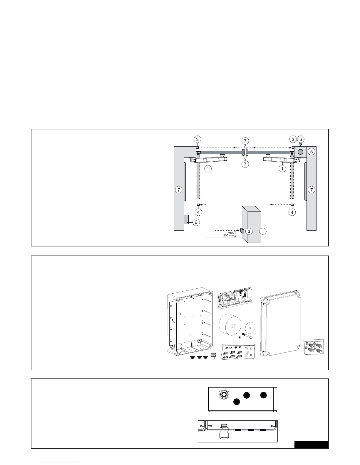
TECHNICAL DATA
Voltage: 230V~ ±10% 50-60Hz
Transformer: 230V/24V, 150VA
Output Motor: 24V/DC
Consumption max.: max. 400W (in operation)
Consumption Standby: max. 4 Watt (without accessories)
Supply accessories: 24VDc / 600mA max.
Operating temperature: -25ºC ÷ 55ºC
Modes: Standard, Automatic
Measurements: 250x75mm (without box)
Measurements Box: ca. 300mm x 220mm x 120mm
Protection class Box: IP45
Fuse: 2 x 2A fast-blow
Remote control: max. 170
Feasible frequencies: 433MHz, 868MHz
TYPICAL CONFIGURATION OF AN INSTALLATION:
1. Operators (LYN/SCS)
2. Control board
3. Photocell (active for closing), max. height 200 mm
First photocell.
4. Photocell (active for opening and closing), max. height 200 mm
Second photocell (optional).
5. Flashing light (optional)
Important visual information on the movement of the gate.
6. Key-operated switch or wireless keypad (optional)
Is mounted on the outside. The gate is opened by key or by
entering a number.
7. Contact strip (optional)
Safeguards the gate on being touched. Contact strips can be
mounted on the gate or on the pillars. If required, contact strips
must be mounted at a height of up to 2.5m.
2/16 en
CONTROL BOX
The control consists of several components.
- exterior installation box 1
- cover for box 1
- control 1
- transformer 1
- baseplate (pre-assembled) 1
- cable bushing large 1
- cable bushing small 3
- fastening clips 6
- screws 3,5 x 9,5 mm 4
- large washer 1
- screw large 1
- spring lock washer 1
- cable lug 1
- nut M8 2
- washer M8 1
- large closure screws 5
PREPARATION
Open the 4 pre-cut holes at the bottom of the casing
with a screwdriver or a similar device. Attach large
cable bushing on the left then the rest as shown in
picture. Humidity and water destroy the control. All
openings and cable bushings must be sealed
against water (waterproof). The control box with the
motor control is to be mounted with the cable
bushings facing down.
4
+
Page 59
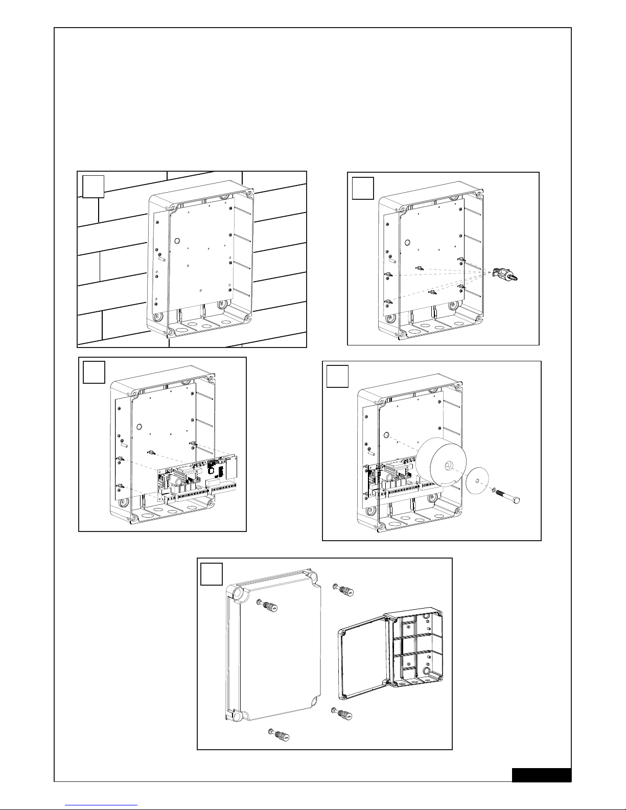
RECOMMENDED PROCEDURE:
Fasten exterior installation box to wall, after previously measuring required distances and establishing correct position of drill-holes (Hardware
not included). Baseplate for transformer is already pre-assembled (A).
Push fastening clips in designated holes (B) .
Push controlboard on to fastening clips (C).
Fasten transformer on to baseplate using the large screw and large washer (D).
Put the 4 large closure screws through cover of the box. Fasten 2 of them (left or right) approx 2cm into the box.
After that the cover can be opened to the side (E).
Close box on a trial basis turning the screws all the way in. If the lid does not close completely, then the box is not fi tted to the wall evenly and is
therefore distorted. This must be corrected. It is very important for the box to be waterproof once closed.
3/16 en
6x
B
C
D
A
E
Page 60
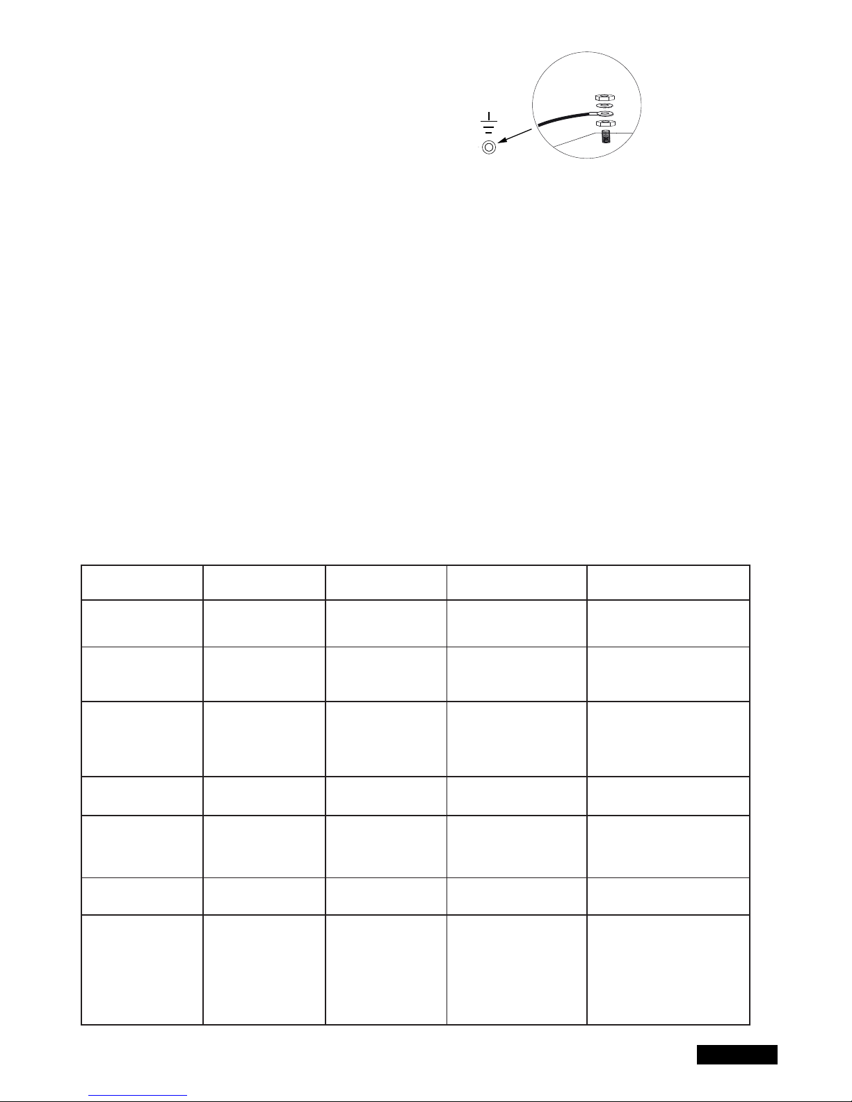
WIRING OF CONTROL / SUMMARY
a) start with 230Volts supply cable.
Run cable through large cable bushing on the lefthand side.
b) Attach cable eye to ground wire. Then connect ground wire to
base plate with washer and nut (exactly as shown in picture detail).
Connect all other cables to control.
CABLES AND WIRING
The usage of shielded cable in order to connect the motor to control board is highly recommended. Magnetic and inductive infl uence of the signal in
the cables can produce electric noise and may disturb the function of the gate .
Generally avoid:
- Control board location far away from gate.
- 230Volt and low voltage in the same power line. Not allowed by electrical rules.
- Wiring of the infrared sensors, switches, fl ashing lamps & electric locks require a cable separately from the motor wiring.
- Other wirings like telephone intercoms, lights for garden etc. must be in separate cables.
- Rigid copper cables especially when thicker diameters are diffi cult to manage during the installation and may result in bad connections with
functional issues. Use instead fl exible cables.
- Cable material not suitable for outside use. Use cables suitable for outside use and underground. Run the cables in conduits if the cable is not
suitable for placing in the ground (armoured or suitably protected). You may also consult your local electrician.
We recommend the following accessories:
- LA400-JB40E Kit for cable extension of one installation unit. Consists of 12m of cable 6-pole with identical colours, distribution box IP65,cable
screw joints and fastening material.
- 041ASWG-0482-50 Cable 50m for professional use. Consists of 50m of cable 6-pole with identical colours. Cut only as much as you need for the
current installation.
General wiring sizes:
The numbers mentioned in the table below are minimum requirements. It is always possible to use larger diameters.
- 230Volt Supply Power to controller: min. 0,75mm² 3-pole
- 230Volt Supply transformer installed separately (i.e. in the garage) and low voltage to gate. See table.
- Motor wiring: 2 wires min. 1,0mm², 4 wires min. 0,75mm² (or shielded cable)
- Electric locks: See table
- Switches, infrared sensors, fl ashing lamp: See table etc. min.0,5mm²
4/16 en
Operator Model
LYN, SCS, ART
motor wiring
SUB (underground)
motor wiring
Transformer separately
installed (in garage) and
low voltage supplied to
control board box.
Electric lock (12Volt)
wiring
External antenna
(Remove original
antenna of logic board)
Switches, Flashing lamp
etc.
Infrared Sensors
Distance
0m - 6m
2 x 1,0mm²
4 x 0,75mm²
2 x 1,0mm²
3 x 0,75mm²
0,75mm²
0,75mm²
Coax cable (Satellite
cable)
50 Ohm
0,5mm²
0,5mm²
Distance
6m - 10m
2 x 1,0mm²
4 x 0,75mm²
2 x 1,0mm²
3 x 0,75mm²
0,75mm²
0,75mm²
Coax cable (Satellite
cable)
50 Ohm
0,5mm²
0,5mm²
Distance
10m - 12m
Normal
Wiring
Use shielded cable for
the 3 smaller motor wires
1,0mm²
1,0mm²
Coax cable (Satellite
cable)
50 Ohm
0,75mm²
0,75mm²
Distance
12m – xx
Max. 15m
Use shielded cable for the 4
smaller motor wires.
Use shielded cable for the 3
smallermotor wires
Max. 30m; Min. 1,5mm²
Gate weight maximum 50% of
maximum motor power rating.
Max. 30m; Min. 1,5mm²
Coax cable (Satellite cable)
50 Ohm
(max. 25m)
Min. 0,75mm²
Max. 30m
Min. 0,75mm²
Max. 20m
Page 61
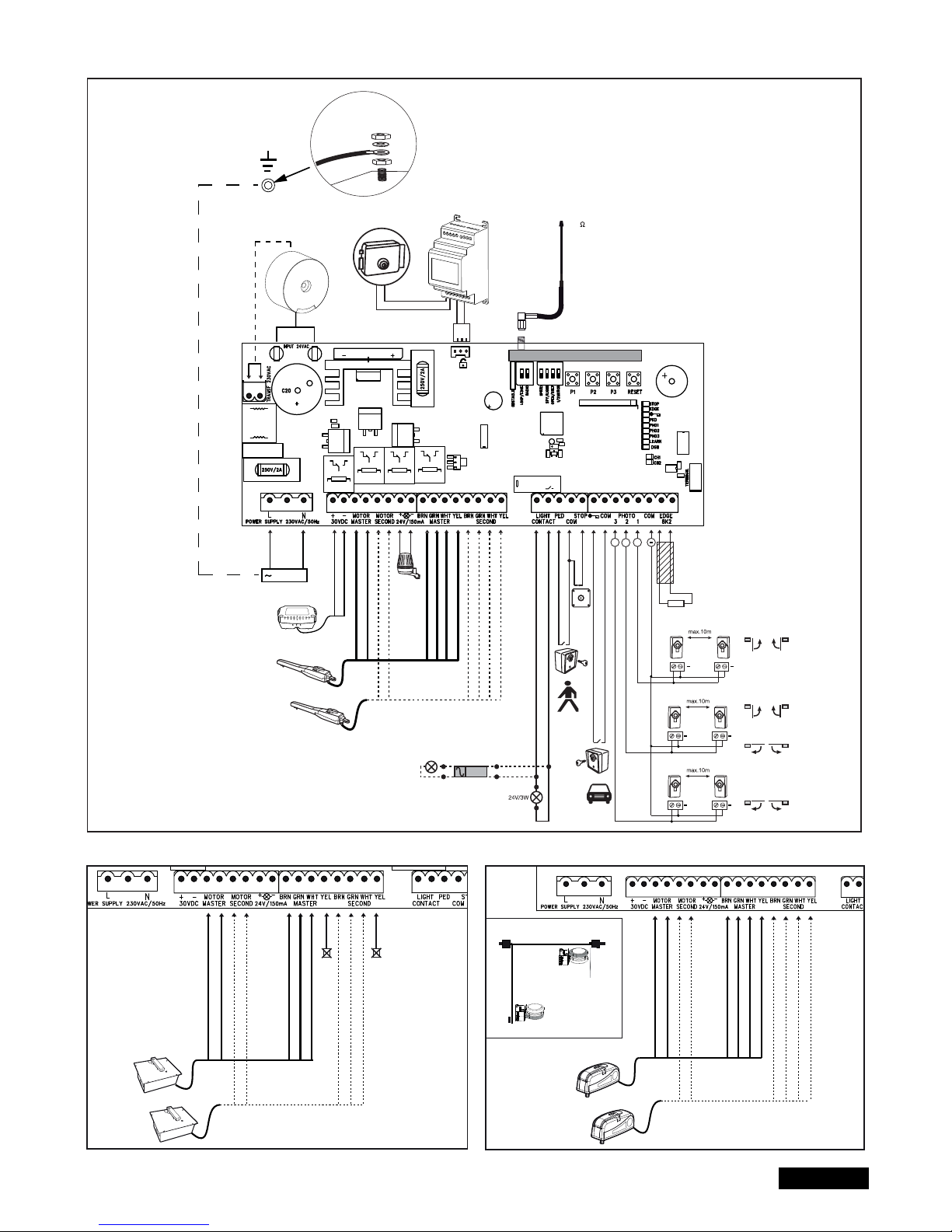
5/16 en
WIRING DIAGRAM
LYN/SCS
230VAC
PE
PE
Model
203285
Ω
8.2
+
+
+
+
+
+
+
Relay
+++
+
-
RED
RED
BLUE
BLUE
Model
CM475
BROWN
GREEN
WHITE
BROWN
GREEN
WHITE
YELLOW
YELLOW
RADIO MODULE
Model
207399
230 VAC
50
RED
RED
BLUE
BLUE
BROWN
GREEN
WHITE
BROWN
GREEN
WHITE
not required
not required
RED
RED
BLUE
BLUE
BROWN
GREEN
WHITE
BROWN
GREEN
WHITE
YELLOW
YELLOW
ART
SUB
Closed position
Open position
external
battery
Page 62
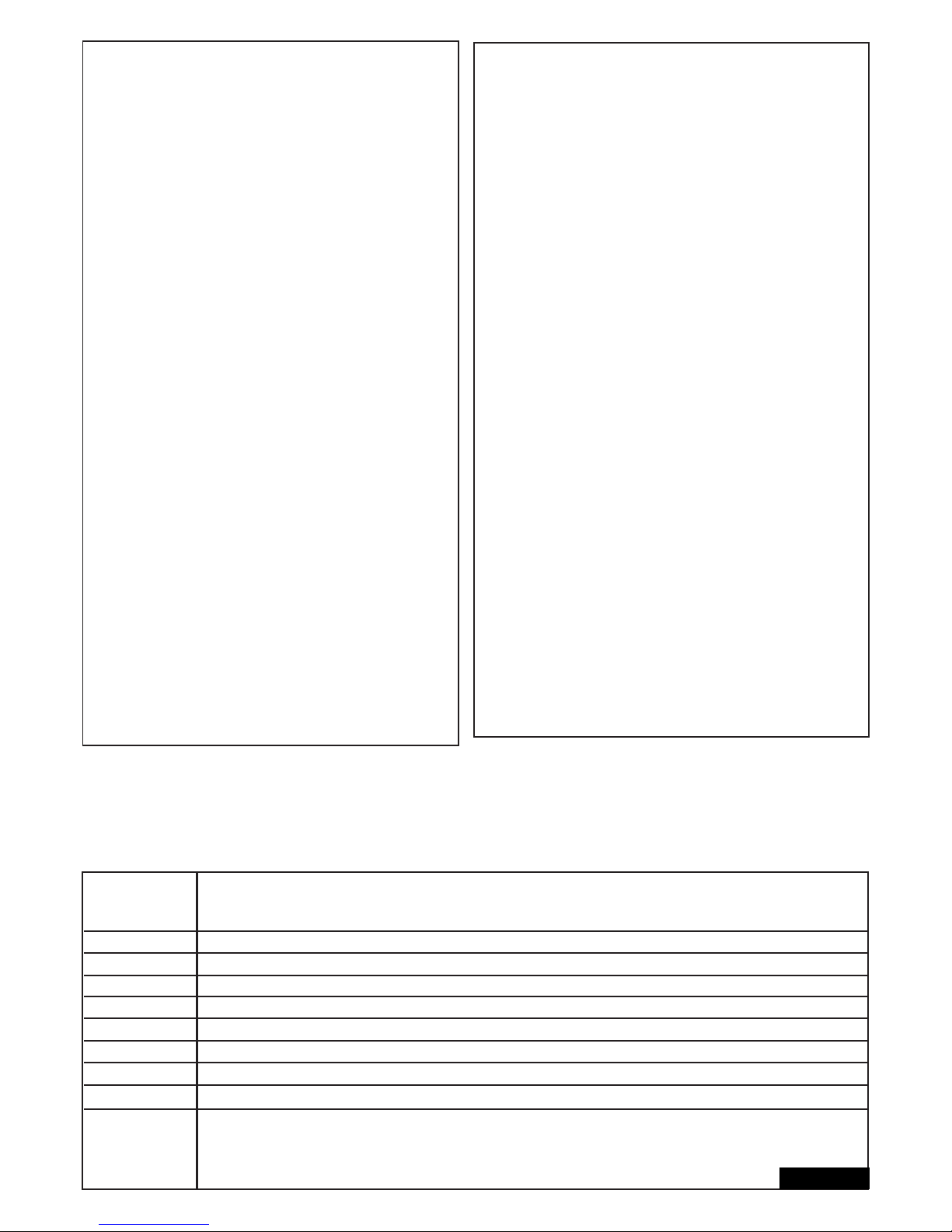
FUNCTIONALITY OVERVIEW OF THE PUSH BUTTONS P1, P2, P3 & RESET
P1+P2+P3
P1
P1 + P2
P2 + P3
P1 + P3
P2
P3
DIP „RADIO“ + P1
DIP „RADIO“ + P2
RESET
Manual operation. The gate wings can be moved electrically in a manual mode. Activate Function: Push P1+P2+P3
simultaneously. The LED LEARN starts to fl ash as long as feature is activated. Button P1 operates Motor1. Button P2 operates
Motor2. Deactivate: Wait for 20 seconds or disconnect logic board power. If wings close at fi rst reverse wires red and blue.
For automatic programming of the automatic travel distance limits of the gate.
For the advanced programming of the travel distance limits of the gate
Electric lock delay time
Wing delay adjustment.
Automatic closing time. Requires also P2 to confi rm.
Software-reset to factory defaults. Push & hold for 10 seconds. Does not reset the remote control memory (see section “radio”).
Programming Remote for Channel 1. Command for both motors (wings)
Programming Remote for Channel 2. Command for single motor (Motor1).
Program Internet Gateway or Door Monitor Note: The RESET button does not perform a reset of this particular control board
to factory defaults . It is only meant to program the Internet Gateway and the Door Monitor. See function P3 for resetting the
board to factory default settings.
Button Function
6/16 en
DESCRIPTION OF TERMINALS
DESCRIPTION FUNCTION
L connector L 230V supply
N connector N 230V supply
30VDC connector for an external battery
Motor MASTER motor 1 (master opens fi rst) red/blue
Motor SECOND motor 2 (Second opens second) red/blue
To check correct polarity refer to section basic setting and
functionality P1+P2+P3 & RESET
24V/150mA fl ashing light (accessory)
Motor1 MASTER
BRN brown cable
GRN green cable
WHT white cable
YEL yellow cable
Motor2 SECOND
BRN brown cable
GRN green cable
WHT white cable
YEL yellow cable
Light Contact gate monitor/ yard lighting
PED key switch
COM negative pole
STOP stop switch
Key symbol key switch
COM negative pole
PHOTO3 photocells 3 (open)
PHOTO2 photocells 2 (close & open)
PHOTO1 photocells 1 (close)
COM negative pole
EDGE safety edge with 8.2KOhms
8.2kOhms
E-lock symbol connection for E-lock control board
INPUT 24VAC 24V power input from transformer.
can be connected with any polarity.
Transformer 230VAC 230V supply to transformer. Can be
connected with any polarity.
250V/2A fuse 250V/2A fast-blow (2x included)
DESCRIPTION OF LED´S (LIGHT EMITTING DIODE)
DESCRIPTION COLOUR STATUS
Stop green Stop Switch
ON: Stop Active
OFF: OK (Requires wire bridge if
no switch is connected)
Edge green Safety Edge 8.2KOhm
ON: Activated
OFF: OK (Requires 8.2KOhm
resistor if not used)
“Key symbol” red Key-switch 2-wing opening
ON: Activated
OFF: OK
PED red Key-switch 1-wing opening
ON: Activated
OFF: OK
PHO 1 red Photocell 1 (close)
ON: OK, photocell
connected (no problem)
OFF: No photocells connected
PHO 2 red Photocell 2 (open & close)
(Refer to photocell 1)
PHO 3 red Photocell 3 (open)
(Refer to photocell 1)
LEARN yellow Programming indicator
ON: (fl ashing)
programming is active
OFF: off
DGN red Diagnostic, Refer to page 15
CH1 red Remote control
programming 2-wing opening
ON: New remote can be
programmed
OFF: off
CH2 red Remote control programming
1-wing opening (Refer to CH1)
Page 63

7/16 en
OPTIONAL ACCESSORIES (also refer to wiring diagram)
RADIO TRANSMITTERS MODELS (OPTIONAL):
TX2EV, TX4EV, TX4UNI (remote controls), 747EV (wireless keypad), 128EV (2-channel wall control)
FLASHING LAMP (OPTIONAL) MODEL: FLA24-2, FLA1-LED
A fl ashing lamp can be connected to the control board (Terminals: 24 V / 150 mA). It indicates gate movement. The fl ashing light should be
mounted as high as possible and in good clear view. The control board emits a constant signal that the lamp converts to a fl ashing signal.
KEY SWITCH (OPTIONAL) MODEL: 100010, 100027, 100034, 100041
The system can be operated by key switch (Terminals: key symbol and COM). Also see OPEN/PED under “DIP SWITCH SETTINGS”.
STOP SWITCH (OPTIONAL) MODEL: 600084
A stop switch to stop the movement of the gate in any direction can be connected to this output
SAFETY EDGE (OPTIONAL) MODEL: 600046, 600053, 600077, 600060
(DIP LOOP/EDGE must be off)
A safety edge working according to the 8.2 kilo ohm principle can be connected to the control board (Terminals: Stop / 8,2 kOhm), i.e. a 8.2 kilo
ohm test resistor is attached to the end of the safety edge. It ensures that the electric circuit is monitored permanently. The control board is
supplied with an 8.2 kilo ohm resistor installed. Several safety edges are connected in series.
PHOTOCELLS (OPTIONAL) MODELS: 771E, 772E
The use of photocells is recommended. Use either model 771E or 772E which is also part of Safety Accessoy Kit APLUS-EV
SAFETY ACCESSORY KIT (OPTIONAL): APLUS-EV
The control board is already supplied with an antenna as standard. For special operating distances, an external antenna from the APLUS-EV
accessory kit (includes Photocell 772E, Flashing Light FLA1-LED, and External Antenna SWG-ANT-EV) can be connected as shown in the
wiring diagram.
myQ (OPTIONAL)
(only with 828EV Internet Gateway):
Allows operating the gate opener via Internet or compatible smartphnone.
DOOR MONITOR (OPTIONAL)
(only with 829EV door monitor):
allows optical and acoustical monitoring of the gate position. The gate can also be closed with the device.
BACKUP BATTERY (OPTIONAL) :
The terminals serve to reload an externally installed storage battery.
The integrated recharger is loaded and in case of power failure the battery provides power. A new fully charged storage battery may provide
power for more than 24 hours. Storage batteries are subject to deterioration and lose capacity. Due to extensive use they lose capacity even
faster. Replace storage batteries after approx. 2-3 years.
E-LOCK (OPTIONAL)
The control board allows the use of a 12V E-lock. (instructions included with E-lock). A transformer (207399) must be connected for the Elock
on the main board. In case the gate pushes too hard for the e-lock to open, a special function can be programmed. Activation time
adjustment: Push P2 and P3 together and hold for approx 5 seconds, and count the number of clicks you hear. The click sound is produced
from a relay (light relay).
1 click = approx. 4 seconds power to e-lock (factory setting)
2 clicks = gate closes for 1 second, then opens. Furthermore, after reaching the closed door position, the drive presses briefl y to support the
snap-in of the electric lock. Note: The door should be equipped with ground stops.
GATE MONITORING or YARD LIGHTING (OPTIONAL)
The Terminals have two functions depending on the position of the DIP Spy/Light. Refer to step “DIP SWITCH SETTINGS” in this manual.
The output has no separate power supply and should be charged only up to 24V.
Gate Monitoring / Status of the gate (Spy)
An LED or 24V/3W max lamp (or relay) can be connected to the terminals to indicate the status of the gate
LED OFF = gate close
LED blinking slow = gate opening
LED ON = Gate open
LED blinking fast = gate closing
Yard lighting / Courtesy lamp for 120 seconds
An 24V/3W max lamp (or relay) can be connected to have 120 seconds output to the terminals, when the gate is receiving a command to Open/Close.
After this time, it will switch OFF automatically
CAUTION: output can be charged only up to 24V/3W or relay must be interposed
Page 64
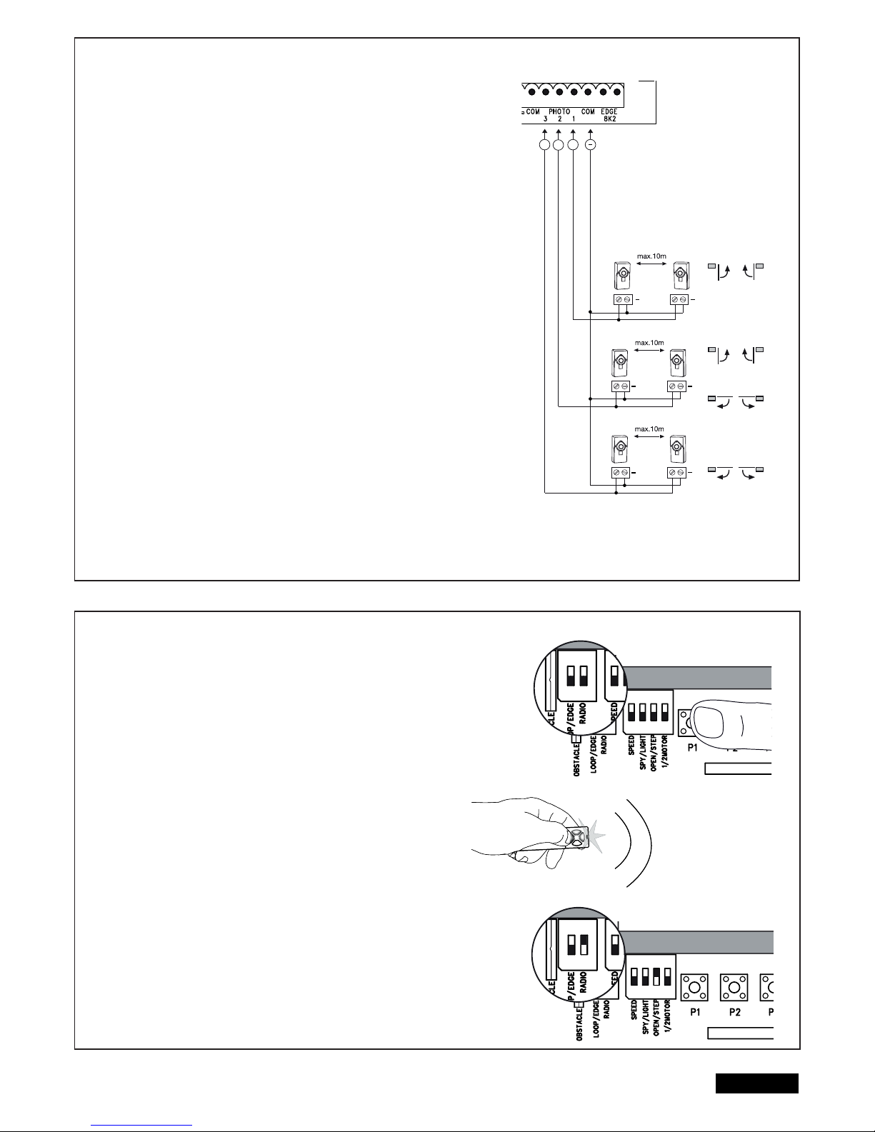
8/16 en
PHOTOCELLS (OPTIONAL) MODEL: 771E, 772E
The photocells are for safeguarding the gate and must be used. The fi tting location
depends on the gate’s design. EN12453 specifi es that a pair of photocells must be in-
stalled at a height of 200 mm and activated to “Close”. The photocells consist of a transmitter and a receiver and must be opposite each other. The photocell is mounted on
the wall using small screws and wall plugs. To enable the “Automatic Closing” function,
the Chamberlain failsafe photocell must be installed. The Chamberlain failsafe system
(2-cable system) has small LEDs (light) that can be seen from the outside on both sides
to indicate the status of the photocell.
Programming of IR sensors:
- connect IR sensors
- program the travel of the gate.
Deletion of IR sensors:
Disconnecting already connected IR sensors will cause the control board to
block the functionality of the terminals it was connected to.
To delete IR sensors correctly:
- disconnect IR sensors
- cut control board from current shortly
- program the travel of the gate.
Diagnosis of the photocell
LED constant = OK
LED fl ashes = photocell disables control board
LED off = no current, incorrect connection or polarity
Diagnosis on the control board
LED off = OK no photocell connected
LED fl ashes = photocell disables control board
Connection between 1 & COM:
Active when gate is closing (reverses gate to open)
Connection between 2 & COM:
Active when gate is closing and opening
Connection between 3 & COM:
Active when gate is opening (holds gate in present position until photocell
is cleared; continues when cleared)
RADIO AND RADIO PROGRAMMING
PROGRAM / DELETE REMOTE CONTROLS
The receiver has two channels CH1 and CH2. Using the different channels
enables the opening of one wing resp. both wings. For example, if CH2=P2
receives the code from the remote control only one wing will open. Choosing
a different button on the remote control in combination with CH1=P1 will
cause both wings to open.
PROGRAMMING
1. Switch on DIP “RADIO”
2. Briefl y push button P1 (for CH1) or P2 (for CH2) and the
respective LED lights up.
3. Press and hold a selected button on your remote control until
LED goes out after 5 times fl ashing. Done!
Repeat for all remote controls (a maximum of 85 remote
controls can be programmed to each channel).
Important: To fi nish programming, Switch off DIP “RADIO”!
Note: Make sure not to program the same remote control button to
CH1 and CH2, otherwise the gate will work improperly.
DELETE
- Switch on DIP “RADIO”.
- Press and hold learn-button P1 for approx. 10 seconds
until LED goes out again. All codes programmed are deleted.
To confi rm both LEDs CH1 and CH2 fl ash 8 times.
- Switch off DIP “RADIO”.
RADIO MODUL
E
ON ON
RADIO MODUL
E
ON ON
RA
ON ON
RA
ON ON
+
+
+
+
+
+
+
+++
Page 65
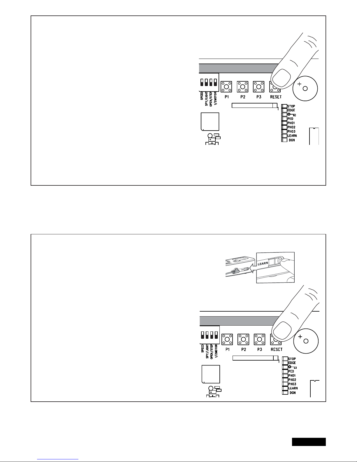
9/16 en
PROGRAM INTERNET GATEWAY myQ
Using the RESET -Button on the control board
1. Connect the ethernet cable to the LiftMaster Internet Gateway
and the router.
2. Connect power to the LiftMaster Internet Gateway.
3. Create an online account on the latest Liftmaster MyQ smartphone
application or on www.liftmaster.eu. It is recommended to use the
smartphone as it will allow you to stand close to the gate while programming
4. Register the LiftMaster Internet Gateway.
5. Click on „Add new device“ and follow the steps given by the
application or on the webpage.
6. Note: When pushing the RESET-Button you will hear a beep and the
LEDs CH1 and CH2 fi rst go on, then after matching, the LEDs will
blink 3 times and go out.
7. The App will tell you if programming was successful and will prompt
you to assign a name to the gate.
PROGRAM DOOR MONITOR
Using the RESET -Button on the control board
1. Connect power to the door monitor.
Position the door monitor in a convenient visible place inside the house.
If this place is too far from the gate opener the connection may not be
possible or is often interrupted.
Choose a more convenient place.
2. Press and release the „LEARN“ button on the back of the door monitor.
Red and green LED blink alternately.
Within 60 seconds press and release the RESET button on the control board.
To confi rm programming red and green LED on the door monitor are on.
DELETE DOOR MONITOR
Press the „LEARN“ button on the back of the door monitor for at least 10 sec.
A short „beep“ confi rms that deleting was successful.
ADIO MODULE
ADIO MODULE
Page 66
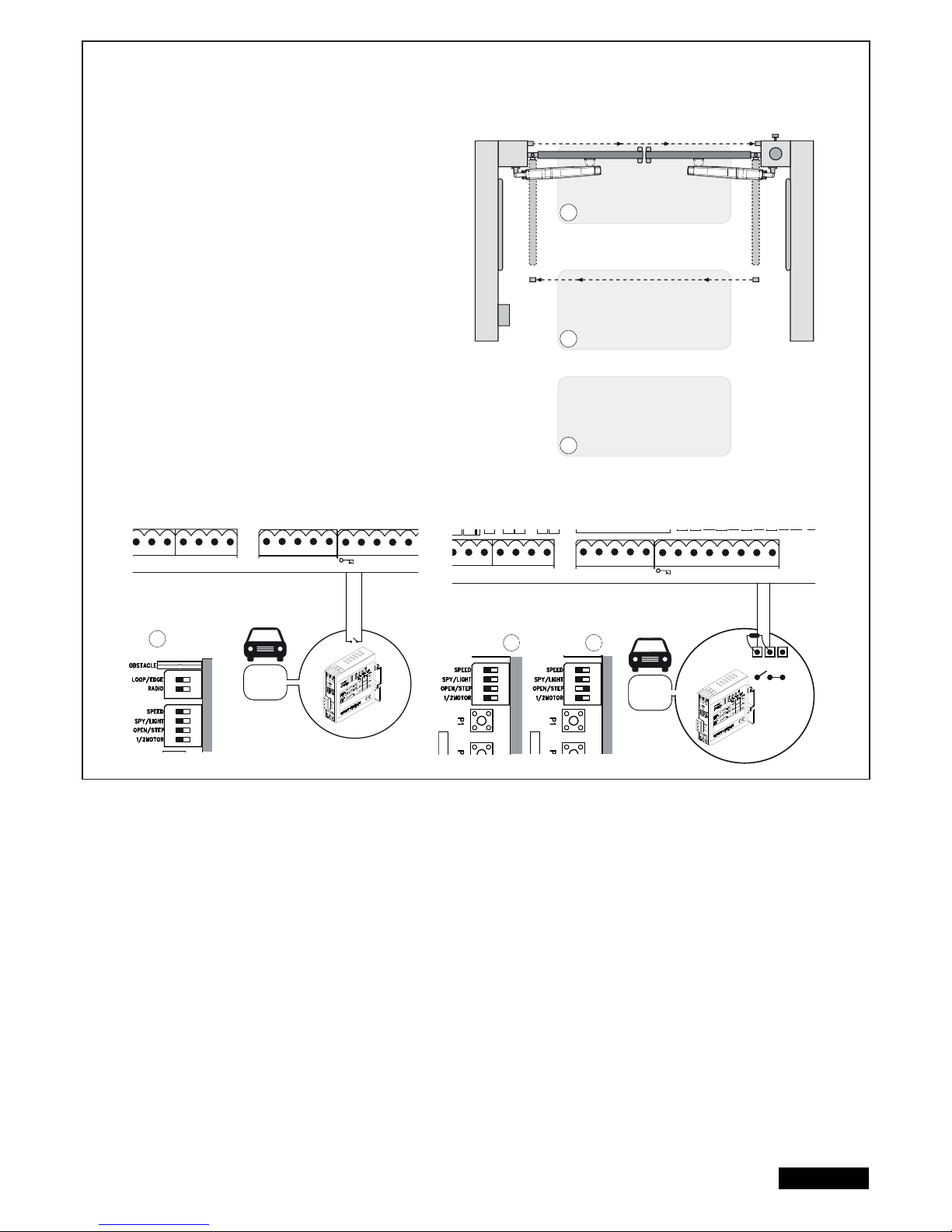
LOOP DETECTOR
Switch on DIP LOOP / EDGE
Loop detectors react to metal and the most common use is for cars
or trucks but not for bikes or pedestrians.
Exit loop / Gate Opening Loop A
An exit loop is behind the gate and opens the gate when closed,
keeps it open or re-opens the gate.
The DIPs OPEN/STEP and LOOP/EDGE must be on. The gate
requires installed photocells and the closing of the gate shall be
activated by the automatic close timer.
Safety/Interrupt loop and Shadow loop B, C
Safety loops can be used to detect cars or truck but do not comply
with regulations as single protection since they do not detect people.
The loop detector control board output is wired as NO signal to the
8.2KOhm safety edge output. In case you use safety edges as well:
Check the functionality you need before installation!
Interrupt loop => DIP OPEN/STEP must be on.
Shadow loop => DIP OPEN/STEP must be off.
Other options for loop detectors can be requested from our service
department.
10/16 en
RN WHT YEL
ASTER
BRN GRN WHT YEL
SECOND
COM
PHOTO
3 2 1
C
LIGHT
CONTACT
PED
COM
STOP
NO
Model
203292
Model
203292
RN WHT YEL
ASTER
BRN GRN WHT YEL
SECOND
COM
PHOTO
3 2 1
COM EDGE
8.2KΩ
LIGHT
CONTACT
PED
COM
STOP
NO
COM
NC
A
B
C
A
B C
RADIO
ON ON
RADIO
MOD
ON
RADIO
MOD
ON
Page 67
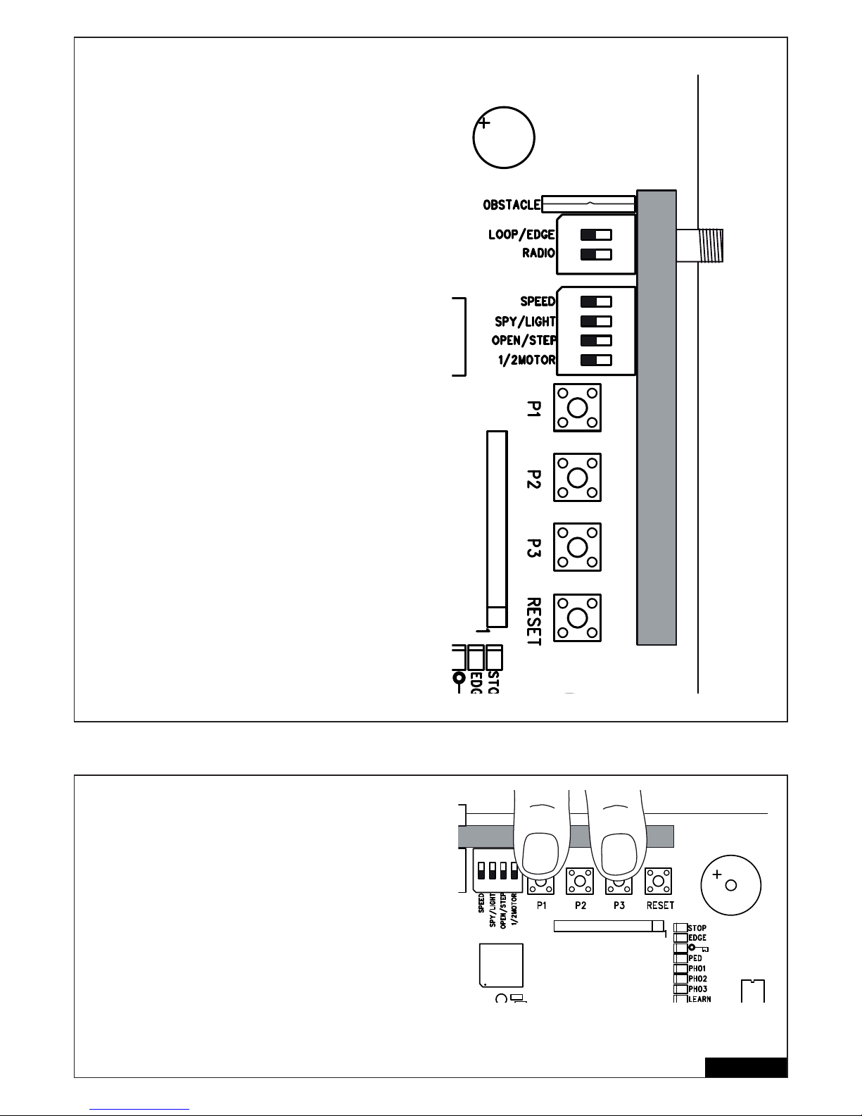
DIP SETTINGS
1 / 2 Motor
Select if 1 or 2 motors are connected to the control board
OFF: 2 Motors connected
ON: 1 Motor connected
OPEN/STEP
Changes the programming and reaction of the gate on commands.
For the use with loop detectors please refer to the loop detector
instruction fi rst.
Step Mode: The gate starts to open if a command is received, next
stop, next closes, next stop, next open…….
OPEN Mode: The gate will not react on a command during the travel
to the gate open position.
OFF: STEP
ON: OPEN
LIGHT/SPY
Gate Monitoring / yard Lighting Select if the function is used or leave free.
OFF: LIGHT(yard lighting)
ON: SPY (gate monitoring)
OBSTACLE
Factory-equipped with wire jumper. Disabling increases the
operating power at the control. CAUTION: If the jumper is
disabled, the door system should be secured with additional
safety devices (contact strip, etc.).
LOOP/EDGE
Select for desired device.
OFF: EDGE
ON: LOOP
SPEED
Select for the type of motor you intend to use.
OFF: Slow ART, LYN, SCS, SUB
ON: Fast LYN, SCS, SUB
RADIO
The DIP “RADIO” is required to program remote controls.
For programming procedure please refer to page 8, section “radio”
OFF: No programming of remote controls possible
ON: Programming of remote controls possible
Important: Switch off DIP “RADIO” if not in use!
Wing Delay Adjustment
The delay of one wing is required to open and close the wings correctly
and to operate the wings with a safe distance from each other. A larger
distance may be required when the mechanical installation distances
are different between the wings or wing length is different. The delay
time in opening direction is fi xed. The closing is adjustable
Push P3 and P1 together and hold for approx 5 seconds, and count
the number of clicks you hear. The click sound is produced from a
relay (light relay).
1 click = small delay, about 4÷8 seconds (factory default settings)
2 click = medium delay, about 8÷12 seconds
3 click = big delay, about 12÷16 seconds
4 click = total delay, wing 1 will close only when wing 2 is completely closed
Delay in opening direction is always 3 to 5 seconds.
5 click = no delay in opening and closing (wings move simultaneously)
Repeat the procedure if required.
11/16 en
RADIO MODULE
RADIO MODULE
ON ON
Page 68
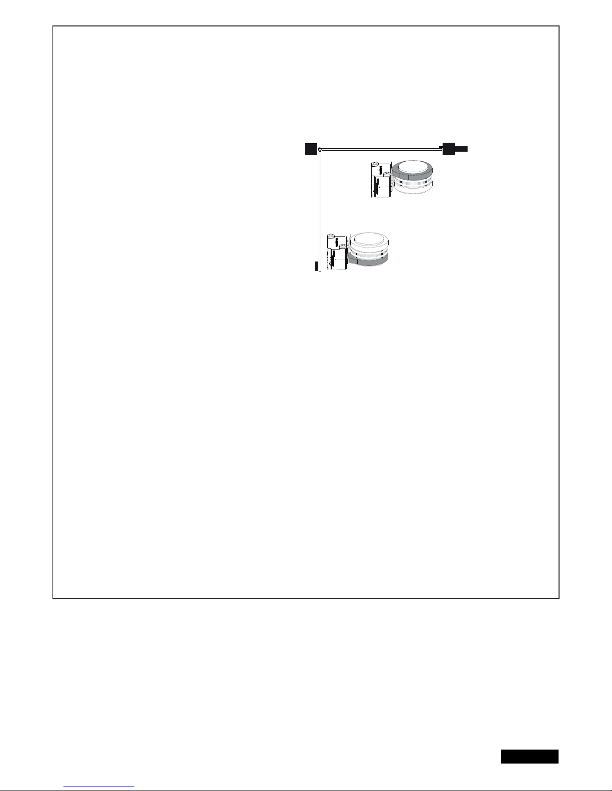
12/16 en
INITIAL OPERATION
BASIC SETTING
Proceed step by step. If you are not sure, start again at the beginning. Take suffi cient time to make these settings.
1. Are all components required for operation connected? Motors, photocells, safety contact strip, stop switch.
2. If your installation consists of only 1 gate (wing) the DIP “1 / 2 Motor” must be on (also refer topage 11, DIP SWITCH SETTINGS).
3. Make sure that nobody is present in the range of the gates.
4. Close the gate/s and attach motor/s.
ART:
- Reference point or “passpoint” has to be adjusted to allow
a successful travel distance programming. The cams under
the cover of the ART need to be positioned correctly. The top
cam clicks the micro switch fi rst and the bottom cam as second.
The micro-switches pushed by the cam shall not be pushed
(clicked) at the same time and shall be not pushed in the end
position of the gate. Twist the cams by using a pair of pliers or
with a large fl at screwdriver.
- Disengage the gate using the release key for this adjustment.
- In case the drive arms are, after this installation step, re-located
the cam position has to be checked if a further adjustment is
required.
- DIP settings for ART: DIP SPEED off!
ART will not work if DIP SPEED is on.
SUB (Underground):
- DIP setting: DIP SPEED on for faster gate movement or off if gate is heavy or safest way of operating is
required. Can be changed any time later after completion of the installation.
LYN-SCS Operator:
- DIP setting: DIP SPEED on for faster gate movement or off if gate is heavy or safest way of operating is required.
Can be changed any time later after completion of the installation.
Now connect the mains supply (230V) to the control board.
BASIC SETTING:
1. Press buttons P1, P2 and P3 simultaneously for approx. 2-3 seconds until yellow LED fl ashes.
2. Monitor the gate. Press and hold P1 for 1-2 seconds. The wing with motor 1 opens. If motor 1 closes, it is wired
incorrectly and the red and blue wires of the motor cable must be reversed. (Caution: Disconnect Power!)
Repeat steps 1 and 2. Leave gate/s in partially open position.
NOTE: General operation – if you release the button, the gate will immediately stop. By pressing the button again the gate will
move in the opposite direction until you release the button, and so on.
3. Press and hold P2 for 1-2 seconds. The wing with motor 2 must open. (Do not open gate completely, only short
distances.) If motor 2 closes, it is wired incorrectly and the red and blue wires of the motor cable must be reversed.
(Caution: Disconnect Power!)
Repeat steps 1 and 2. Leave gate/s in partially open position.
NOTE: The control board is active for this manual setting mode for approx. 20 seconds. If necessary, start again by pressing P1,
P2 and P3 simultaneously.
Now check the following:
1. SCS only: During opening the front housing must not touch the gate. Stop opening several times and check. If housing
touches the gate dimensions A/B must be checked and if necessary, underlay the gate pillar with fl at washers in order to
enlarge clearance.
2. Both wings must open completely. Do not open the wings too far! If there are no stops, choose and mark a position for
maximum opening.
3. SUB (underground operator) only: Now adjust your hard-stop in the box.
Wait until learn-LED goes out (20 seconds after a button was pressed).
Cl
osed pos
iti
on
Open position
gate open
gate closed
Page 69

13/16 en
PROGRAMMING TRAVEL DISTANCES “SIMPLE I”
NOTE: End stops must be available in CLOSED and OPEN modes.
1. Wings must be closed
2. Press P1 until wing / motor 1 starts opening (learn-LED fl ashes)
Automatic programming starts (slow travel)
Wing 1 moves to the stop in OPEN position
Wing 2 moves to the stop in OPEN position
Then wing 2 moves to the stop in CLOSE position.
Then wing 1 moves to the stop in CLOSE position.
When the learn-LED goes out the programming has fi nished.
PROGRAMMING TRAVEL DISTANCES “SIMPLE II”
NOTE: If there are no stops at the OPEN position, the wing should be stopped at opening angle of 90 degrees.
1. Both wings must be closed.
2. Press P1 until wing / motor 1 starts opening
3. Press P1 hard when wing / motor 1 reaches OPEN position. Wing 2 starts.
4. Press P1 hard when wing / motor 2 reaches OPEN position. After that wing 2 closes automatically. The wing 1 closes automatically.
5. The motors “learn” the CLOSE position automatically.
If required, individual CLOSE positions can be programmed as well. Press P1 hard at the desired CLOSE position for each wing.
When the learn-LED goes out the programming has fi nished.
PROGRAMMING TRAVEL DISTANCES “ADVANCED”
NOTE: In this mode P1 must be pressed 9 times.
With every time the button is pressed a position (time) is stored. (This allows programming of SOFT-STOP (slow travel) in order to adjust to
application. Long or short phases of SOFT-STOP are possible.
1. Both wings must be closed.
2. Press P1 and P2 for approx.5-6 seconds until wing / motor 1 starts opening. Release buttons!!!
3. Press P1 again. SOFT-STOP for wing / motor 1 in OPEN direction starts at this point.
4. Press P1 again when OPEN position is reached.Now wing / motor 2 starts automatically to open.
5. Press P1 again. SOFT-STOP for wing / motor 2 in OPEN direction begins at this point.
6. Press P1 again when OPEN position is reached. Now wing / motor 2 starts closing automatically.
7. Press P1 again. SOFT-STOP for wing / motor 2 in CLOSE direction begins at this point.
8. Press P1 again when CLOSE position is reached. Now wing / motor 1 starts automatically to close.
9. Press P1 again. SOFT-STOP for wing / motor 1 in CLOSE direction begins at this point.
10. Press P1 again when CLOSE position is reached. Done!
NOTE: If one wing reaches a stop and button P1 is not pressed, then the motor moves towards the stop and stores this position automatically.
Page 70
14/16 en
COMPLETION OF INSTALLATION / PROGRAMMING
Once the travel distances are programmed, the remote controls can be programmed as well. (Refer to RADIO AND RADIO PROGRAMMING ).
1. You can now let the door run 2 complete cycles by pressing a key on the remote or a connected switch and observe the process.
Close the door again, WITHOUT making another setting.
2. If all adjustments are done, check operation of photocells, switch, fl ashing light, remotes, accessories, etc.
3. Advise people using the gate with regard to gate operation, safety functions and how to release the gate in order to operate it manually.
TIMER TO CLOSE (AUTO-CLOSE)
NOTE: Only possible with connected photocells (1 + COM). Time frames from 2 seconds up to 120 seconds are possible.
Activate:
1. Press and hold P2 until yellow LED starts fl ashing
2. Now count the time you wish to program
3. Press P2 again. Done!
Deactivate:
1. Press and hold P2 until yellow LED starts fl ashing.
2. Press P3. Yellow LED goes out. Done!
FORCE / TORQUE OF MOTOR
Thrust of the motor is set automatically while programming the travel
distance. Thrust can only be modifi ed by programming the travel
distance again. If gate movement is impeded by weather or changes
to the installation (rust or inappropriate lubrication) it may have to be
repaired.
The control board complies with the latest EU guidelines.
One of these guidelines specifi es that the closing forces
at the gate edge must not exceed 400N (40 kg) for the last 500 mm
before the door is CLOSED. Above 500 mm, the maximum force at
the gate edge must not exceed 1400 N (140 kg). If this cannot be
ensured, a safety edge must be mounted on the gate at a height up
to 2.5 m or on the pillar on the opposite side (EN12453).
DISPOSAL
The packaging is made from environmentally friendly materials. It can be disposed of in the local recycling bin. According to the European
Directive 2002/96/EC on waste electrical and electronic equipment, this device must be properly disposed of after use to ensure the reuse of
materials. The information on the possibilities of this waste disposal is provided by the local government or municipality.
BATTERY DISPOSAL
Batteries and rechargeable batteries may not be disposed along with domestic waste, but are
obliged to be returned.
After use they can be returned free of charge locally e.g. in trade or at municipal collecting points.
Batteries and rechargeable batteries are marked with a crossed waste container as well as with the
chemical symbol which describes their toxic element, “Cd” for cadmium, “Hg” for mercury and “Pb” for lead.
12VDC
Pb Cd Hg
Page 71

15/16 en
INDICATION OF THE DIAGNOSIS LED
The LED diagnostics show the fi rst upcoming issue. If several issues are existing the LED diagnostics may not show them.
Indication
1x blinking
2x blinking
3x blinking
4x blinking
5x blinking
6x blinking
7x blinking
8x blinking
9x blinking
10x blinking
11x blinking
12x blinking
13x blinking
14x blinking
15x blinking
Description
Motor 1 has insuffi cient connection to control board
Control board does not see motor sensor.
Travel distance programming was not successful
Motor 2 has insuffi cient connection to control board
Limits for motor 2 have not been accepted
A: After or during programming travel: Wing 1 did not
open wide enough and did not meet the integrated
passpoint which is located inside the operator halfway above the spindle.
B: Motorcables have insuffi cient connection to contol
board
Yellow or white cable not wired or badly connected
Limits for motor 1 have not been accepted
Travel has not been programmed
The process of programming has been interrupted
Force to operate the gate is too high
A: Gate is out of order
B: Gate is rough-running
C: Gate stopped through windload
D: Wrong mechanical installation
Photocells 1 block installation + LED PHO1 =OFF
A: Object blocks photocells
B: Alignment of the sensors is incorrect
C: Power supply to photocells is insuffi cient
Photocells 2 block installation
Photocells 3 block installation
Emergency stop switch blocks installation
Safety edge blocks installation
A: Object obstructs safety edge
B: Defective safety edge
C: Power too low or broken wire in supply
Power supply to control board is too low
A: Defective supply 230V or malfunctioning contact
B: Broken wire in supply cable (copper cable)
C: The battery (accessory) to operate the gate whilst
power failure is dead.
EEPROM Fault
Power up failed
Only LYN/SCS
Release lever OPEN
Defect on relay or major electrical component
A: Overload
B: Bad wiring (wrong)
C: water in photocells (bad installation)
D: a photocell was connected before but not removed
(disconnected)
Remedy
Cables not wired or badly connected.
Check terminals precisely. Consider wire lengths
The gate must be closed completely before programming the
travel distance
Refer to 1x blinking
A: Open gate wide enough when programming the travel (50%
over maximum)
B: Check terminals precisely. Consider wire lengths
C: See 1x blinking (wiring)
Refer to 3x blinking
The gate must be closed completely before programming the
travel distance.
Refer to 5x blinking also
A: Repair gate
B: Check if gate can be easily moved
C: Do not operate gate in very windy conditions
D: Reprogram to achieve suffi cient level of force
A: Remove object
B: Check alignment
C: Check cable widths and contacts
Refer to 7x blinking
Refer to 7x blinking
A: Check wiring
B: Check basic setting of control board (DIPs)
A: Remove object
B: Check wiring. Check resistor 8.2KOhms
C: Check basic setting of control board (DIPs)
A: Check electric contact
B: Check by electrician
C: Allow battery to charge 24 hours
Replace contol board
Close (re-connect) release lever
Replace logic board
Check wiring
Reprogram the travel distance from gate fully closed
Page 72

16/16 en
FAQs
Pressing P1, P2 and P3 does not show any reaction
The gate opener doesn’t respond at all; no LED is
on.
Immediately after the gate has started moving, it
stops and reverses.
Gate can only be opened
“
Timer to close” doesn’t work.
The control board does not work any more using
the transmitter, only with the switch and even then
only as long as a button is pressed and kept
pressed.
The gate opener doesn’t respond at all, although
the controller has been connected (LEDs are on).
Control board does not work with transmitter
Control board does not work
Gate doesn’t open completely
Travel distance can’t be programmed
The operator sometimes movess slowly
Possibly power failure.
Obstacle in area of gate.
Gate rough running (consult dealer)
photocell blocks
Photocell, a safety edge or the emergency
stop disables the control board
Only one photocell was connected for OPEN
1. Remote control not programmed.
2. LEDs indicate a fault.
3. Photocell connected incorrectly.
4. Motor terminal possibly not connected
properly.
1. transmitter not programmed
2. photocells block
3. DIP “RADIO” is on
travel distance not programmed
Gate heavy / rough running
1. DIP setting not correct
2. Motor wiring not correct or cable broken
3. Diagnostic LED
4. Electric noise in wiring disturbs
5. Gate moves for 1 second only and stops
without reversal during programming
6. ART only: Passpoint adjustment incorrect
7. ART only: Motor disengaged
Powerfailure
DIP “RADIO” must be off
1. Check conductor and zero conductor.
2. Check house fusing.
Check gate area for objects
check photocells
reprogram travel distance
Function and connection must be
checked
Only works if the 2-cable photocell 771E(ML)
or 772E(ML) installed.
At least 1 pair of photocells active in
OPEN or CLOSED must be connected
1. Programming remote control.
2. Find and rectify fault(s) (see description of
diagnostic LEDs).
3. Check photocell connection / programming.
4. Check terminals and connections.
1.Program transmitter
2.Check photocells, check diagnostic LEDs
3. DIP “RADIO” must be off.
Program travel distance. See initial
operation / diagnosis LED
re-program travel distance
consult dealer/specialist
1. Check manual, especially “1/2 Motor”
2. If motor is moving check brown, green, white,
yellow cable. Test with different cable to exclude that the defect is the cable in the ground.
Or connect for testing the motor direct to the
control board without extension cable.
3. Check diagnostic for route cause.
4. Refer to solution 2 and if applicable change
wiring type or routing. Verify wiring with manual
recommendation.
5. Not enough electrical power (volts) or bad
wiring. Refer to solution 2.
6. Adjust passpoint cams in motor. Refer to
ART manual.
7. Engage motor. Refer to ART manual.
Common procedure. After powerfailure the
operator performs a selftest. Depending on
the operator model this can take a few
seconds or a complete cycle. Do not interrupt
this test via remote control or switch,
otherwise the limits may change. If this is the
case reprogram travel distance using P1.
The remote control’s range is too short. The installation of an external antenna is recommended as the controller with the short cable
antenna is located either behind the post or near ground level in most cases. The optimum
location of the antenna is as high as possible in all cases. An appropriate antenna with
installation kit can be obtained as an accessory.
The gate must follow a slope. Not recommended! Change gate! The gate can move in an uncontrolled (dangerous) manner if
the gate opener has been released. A stronger force is needed in the upwards direction of the
slope and then, in the opposite direction, the gate opener’s force is too strong.
The gate post is so thick that I am unable to Reduce post thickness or shift gate location
comply with the requisite A+B dimensions.
Page 73

TÉMA STRANA
BEZPENOSTNÍ PRAVIDLA . . . . . . . . . . . . . . . . . . . . . . . . . . . . . . . . . . . . . . . . . . . . . . . . . . . . . . . . . . . . . . . . . . . . . . . . . . . .1
TECHNICKÉ ÚDAJE K ÍDICÍ JEDNOTCE MOTORU . . . . . . . . . . . . . . . . . . . . . . . . . . . . . . . . . . . . . . . . . . . . . . . . . . . . . . . .2
TYPICKÁ KONSTRUKCE ZAÍZENÍ . . . . . . . . . . . . . . . . . . . . . . . . . . . . . . . . . . . . . . . . . . . . . . . . . . . . . . . . . . . . . . . . . . . . . 2
INSTALACE ÍDICÍ JEDNOTKY . . . . . . . . . . . . . . . . . . . . . . . . . . . . . . . . . . . . . . . . . . . . . . . . . . . . . . . . . . . . . . . . . . . . . . . . .2
PÍPRAVA ÍDICÍ JEDNOTKY . . . . . . . . . . . . . . . . . . . . . . . . . . . . . . . . . . . . . . . . . . . . . . . . . . . . . . . . . . . . . . . . . . . . . . . . . . 2
DOPORUENÝ POSTUP . . . . . . . . . . . . . . . . . . . . . . . . . . . . . . . . . . . . . . . . . . . . . . . . . . . . . . . . . . . . . . . . . . . . . . . . . . . . . . .3
KABELÁŽ ÍDICÍ JEDNOTKY . . . . . . . . . . . . . . . . . . . . . . . . . . . . . . . . . . . . . . . . . . . . . . . . . . . . . . . . . . . . . . . . . . . . . . . . . . .4
PIPOJOVACÍ DIAGRAM . . . . . . . . . . . . . . . . . . . . . . . . . . . . . . . . . . . . . . . . . . . . . . . . . . . . . . . . . . . . . . . . . . . . . . . . . . . . . . 5
POPIS / FUNKCE PIPOJENÍ . . . . . . . . . . . . . . . . . . . . . . . . . . . . . . . . . . . . . . . . . . . . . . . . . . . . . . . . . . . . . . . . . . . . . . . . . . .6
POPIS LED DIOD . . . . . . . . . . . . . . . . . . . . . . . . . . . . . . . . . . . . . . . . . . . . . . . . . . . . . . . . . . . . . . . . . . . . . . . . . . . . . . . . . . . . .6
POPIS TLAÍTEK P1, P2, P3 & RESET . . . . . . . . . . . . . . . . . . . . . . . . . . . . . . . . . . . . . . . . . . . . . . . . . . . . . . . . . . . . . . . . . . . 6
PÍSLUŠENSTVÍ VOLITELNÝ . . . . . . . . . . . . . . . . . . . . . . . . . . . . . . . . . . . . . . . . . . . . . . . . . . . . . . . . . . . . . . . . . . . . . . . . . . 7
SVTELNÁ ZÁVORA . . . . . . . . . . . . . . . . . . . . . . . . . . . . . . . . . . . . . . . . . . . . . . . . . . . . . . . . . . . . . . . . . . . . . . . . . . . . . . . . . .8
PROGRAMOVÁNÍ DÁLKOVÝCH OVLADA . . . . . . . . . . . . . . . . . . . . . . . . . . . . . . . . . . . . . . . . . . . . . . . . . . . . . . . . . . . . . .8
NAPROGRAMOVÁNÍ INTERNETOVÉHO ROZHRANÍ MYQ / KONTROLY VRAT . . . . . . . . . . . . . . . . . . . . . . . . . . . . . . . . . 9
POUŽITÍ SMYKOVÝCH DETEKTOR . . . . . . . . . . . . . . . . . . . . . . . . . . . . . . . . . . . . . . . . . . . . . . . . . . . . . . . . . . . . . . . . . . . 10
NASTAVENÍ DIP SPÍNA. . . . . . . . . . . . . . . . . . . . . . . . . . . . . . . . . . . . . . . . . . . . . . . . . . . . . . . . . . . . . . . . . . . . . . . . . . . . . 11
NASTAVENÍ PRODLEVY KÍDEL . . . . . . . . . . . . . . . . . . . . . . . . . . . . . . . . . . . . . . . . . . . . . . . . . . . . . . . . . . . . . . . . . . . . . . . .11
PRVNÍ UVEDENÍ DO PROVOZU . . . . . . . . . . . . . . . . . . . . . . . . . . . . . . . . . . . . . . . . . . . . . . . . . . . . . . . . . . . . . . . . . . . . . . . . .12-14
AUTOMATICKÉ ZAVENÍ . . . . . . . . . . . . . . . . . . . . . . . . . . . . . . . . . . . . . . . . . . . . . . . . . . . . . . . . . . . . . . . . . . . . . . . . . . . . . .14
PÍKON . . . . . . . . . . . . . . . . . . . . . . . . . . . . . . . . . . . . . . . . . . . . . . . . . . . . . . . . . . . . . . . . . . . . . . . . . . . . . . . . . . . . . . . . . . . . 14
LIKVIDACE / LIKVIDACE BATERIÍ . . . . . . . . . . . . . . . . . . . . . . . . . . . . . . . . . . . . . . . . . . . . . . . . . . . . . . . . . . . . . . . . . . . . . . .14
DIAGNOSTICKÁ LED DIODA . . . . . . . . . . . . . . . . . . . . . . . . . . . . . . . . . . . . . . . . . . . . . . . . . . . . . . . . . . . . . . . . . . . . . . . . . . . 15
ASTO KLADENÉ DOTAZY . . . . . . . . . . . . . . . . . . . . . . . . . . . . . . . . . . . . . . . . . . . . . . . . . . . . . . . . . . . . . . . . . . . . . . . . . . . . 16
Page 74
1/16 cz
POZOR
DLEŽITÉ POKYNY K MONTÁŽI A POUŽITÍ
ZANTE TÍM, ŽE SI PETETE TATO DLEŽITÁ BEZPENOSTNÍ PRAVIDLA
Tyto výstražné symboly znamenají „Pozor!“, výzvu k pozornosti, nebo jejich nerespektování by mohlo zpsobit
poškození lidského zdraví nebo vcné škody. tte prosím tato varování peliv.
Tento pohon brány je konstruován a testován tak, že pi instalaci a používání zaruuje pi pesném dodržení
bezpenostních pravidel pimenou bezpenost.
Dsledkem nerespektování tchto bezpenostních pravidel mohou být škody na zdraví osob nebo vcné škody.
Pi manipulaci s náadím a drobnými
souástkami postupujte opatrn a nenoste
prsteny, hodinky, ani volné obleení, jestliže na
brán provádíte instalaní práce nebo opravy.
Elektrická vedení je nutné klást v souladu s
místními stavebními a elektroinstalaními
pedpisy. Elektrický kabel smí k ádn
uzemnné síti pipojit pouze autorizovaný
odborník - elektriká.
Pi montáži je nutné zohlednit nebezpeí sevení
mezi pohánnou ástí a okolními ástmi budovy
(nap. stnou) na základ otevíracího pohybu
pohánné ásti.
Odstrate prosím z brány všechny
namontované zámky, abyste zabránili jejímu
poškození.
Po instalaci je nutné zkontrolovat, zda je
mechanismus správn seízený a zda pohon,
bezpenostní systém a nouzové odblokování
správn fungují.
Jsou-li v brán prchozí dvee, nelze poháncí
mechanismus spustit nebo nechat bžet, dokud
není brána ádn uzavena.
K zabránní poškození zejména lehkých vrat
namontujte píslužné zesílení. Obrate
se s tím prosím na výrobce vrat.
Toto zaízení nesmí být obsluhováno osobami
(vetn dtí), které jsou fyzicky nebo duševn
postiženy nebo které nemají dostatené
zkušenosti s manipulací se zaízením, pokud
nejsou pod dozorem nebo nejsou poueny
osobou odpovdnou za jejich bezpenost o
manipulaci se zaízením..
Vlhkost a voda psobí na ídicí elektroniku
niiv. Za každých okolností zajistte, aby do
ídicí elektroniky nepronikla vlhkost a voda,
nebo aby nedocházelo k jejímu zadržování v
zaízení.
Je dležité, aby se brána stále hladce
pohybovala. Brány, které se zaseknou nebo se
vzpíí, je nutné okamžit opravit.
Nepokoušejte se bránu opravovat sami.
Penechejte opravu odborníkovi.
Doplkové píslušenství odstrate z dosahu
dtí. Nedovolte dtem, aby zacházely stlaítky a
dálkovým ovládáním. Zavírající se brána mže
zpsobit tžká poranní.
Pi provádní údržbových prací jako je napíklad
ištní, musejí být automaticky ovládané pístro-
je odpojené ze sít.
V pevn zapojené instalaci je nutné pamatovat
na rozpojovací zaízení, aby bylo zarueno ve
všech pólech odpojování spínaem (rozevení
kontakt min. 3 mm) nebo samostatnou pojistkou.
Zajistte, aby osoby, které montují, udržují a
obsluhují pohon, dodržovaly tento návod. Uložte
tento návod na takovém míst, kde je rychle k
dispozici.
Po montáži pohonu musí být zaruena defi -
nitivní ochrana míst, kde hrozí pohmoždní a
poezání.
Automatický vratový pohon – nezdržujte se v
oblasti vrat, protože se mohou zaít neekan
pohybovat. Je teba dohlížet na dti, aby se
zajistilo, aby si se zaízením nehrály.
Pi provozu nesmí vrata za žádných okolností
omezovat veiejné prchody.
Tento návod je teba uchovávat!
Page 75
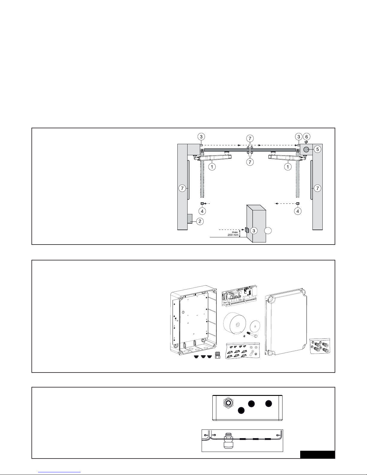
TECHNICKÉ ÚDAJE ÍDICÍ JEDNOTKY MOTORU
Naptí: 230 V ~ +/- 10 % 50-60 Hz
Transformátor: 230/24 VAC, 150 VA
Výstup motoru: 24 VDC
Max. spoteba: max. 400 W (v provozu)
Spoteba v pohotovostním režimu: max. 4 W (bez píslušenství)
Napájení píslušenství: 24 VDC / 600 mA max.
Pracovní teplota: -20 şC ÷ +55 şC
Pracovní postup: Standard, automatika
Rozmry: 250 x 75 mm (bez skín)
Rozmry skín: cca 300 x 220 x 120 mm
Krytí: IP45
Pojistka: 2x rychlospouštcí 2 A
Runí dálkový ovlada: max. 170 x Rolling Code
možné frekvence: 433 MHz, 868 MHz
TYPICKÁ KONSTRUKCE ZAÍZENÍ
1. Motor
2. ídicí elektronika
3. Svtelná závora (aktivní pi zavírání), výška max. 200 mm
První svtelná závora.
4. Svtelná závora (aktivní pi otevírání / zavírání), výška
max. 200 mm. Druhá svtelná závora (volitelné píslušenství).
5. Výstražná svtelná signalizace (volitelné píslušenství)
Dležité optické upozornní na pohyb brány.
6. Uzamykatelný vypína (volitelné píslušenství).
Je umístn na venkovní stran. Brána se otevírá klíem nebo
zadáním íselného kódu.
7. Bezpenostní lišta (volitelné píslušenství).
Zajišuje bránu pi dotyku. Bezpenostní lišty lze instalovat na
brán nebo na sloupcích. Bezpenostní lišty musí být
umístny pokud je to nutné, až do výšky 2,5 m.
2/16 cz
MONTÁŽ BOXU ÍDICÍ ELEKTRONIKY
V boxu ídicí elektroniky se nachází více díl:
- Box pro vnjší montáž 1x
- Víko boxu 1x
- ídicí elektronika 1x
- Transformátor 1x
- Základna transformátoru 1x
- Kabelová prchodka velká 1x
- Kabelová prchodka malá 3x
- Pøídrné spony 6x
- Šrouby 3,5 x 9,5 mm 4x
- velká podložka 1x
- dlouhý šroub 1x
- kabelová svorka 1x
- matka M8 2x
- podložka M8 1x
- velké závrné šrouby 5x
PÍPRAVA BOXU ÍDICÍ ELEKTRONIKY
Udlejte v spodní ásti krytu 4 otvory pomocí
šroubováku nebo podobného nástroje. Velkou
kabelovou prchodku upevnte vlevo, zbytek, jak je
ukázáno.
Vlhkost a voda psobí na ídicí elektroniku niiv.
Všechny otvory a kabelové prchodky musí být
bezpodmínen vodotsn uzaveny. Namontujte
box ídicí elektroniky se systémem ízení motoru
kabelovými prchodkami dol.
4
+
Page 76
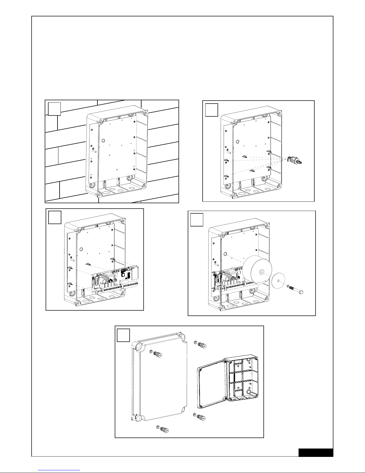
DOPORUENÝ POSTUP
Našroubujte spodní ást krytu na stnu. Pedtím odmte náležité odstupy a urete pesné vrtané otvory. (Upevovací materiál není piložen.)
Montážní deska je už namontovaná v krytu (A).
Pídržné spony zatlate do urených otvor (B).
ízení natlate na pídržné spony (C).
Transformátor našroubujte pomocí velkého šroubu a velké podložky na montážní desku. (D)
Víkem boxu prostrte 4 velké závrné šrouby boxu. Zašroubujte (vlevo nebo vpravo) 2 závrné šrouby pibližn 2 cm do boxu.
Víko se pak dá odklopit do strany (E).
Na zkoušku uzavete box tím, že šrouby úpln zašroubujete. Pokud víko správn nedoléhá, piléhá box ke stn nerovnomrn a tím je
zkroucený. Je nutná úprava. Je velmi dležité, aby se box dal pozdji vodotsn uzavít.
3/16 cz
6x
B
C
D
A
E
Page 77
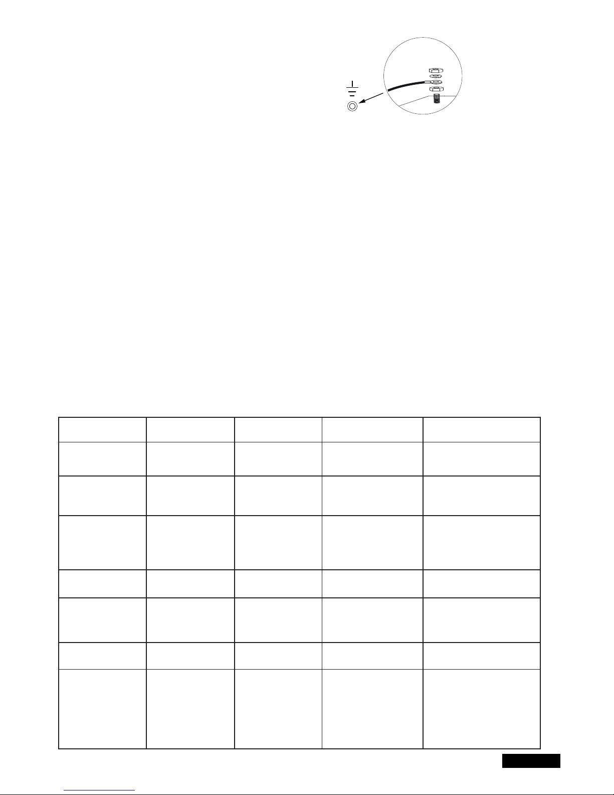
KABELÁŽ ÍDICÍ ELEKTRONIKY / PEHLED:
a. Zante s pívodním kabelem 230 V, který je ješt bez naptí,
na levé stran boxu.
b. Umístte kabelovou svorku na uzemovací vodi.
Spojte uzemovací vodi pívodu se základovou deskou.
Pipojte všechny ostatní kabely na ídicí elektroniku.
KABELY A KABELÁŽ
Doporuuje se použití odstínných kabel od motoru k ídicí jednotce.
Magnetický a indukní vliv mže v kabelu vyvolat bzuení a narušit funkci brány.
Obecn se vyhnte:
- umístní ídicí jednotky píliš daleko od brány.
- pokládání 230voltových vedení a vedení nízkého naptí spolen. Podle pedpisu týkajícího se elektroinstalace nepípustné.
- kabely pro svtelné závory, spínae, majáek a elektronický zámek nepokládejte spolen s kabelem motoru.
- telekomunikaní kabely nebo vedení pro zahradní osvtlení rovnž nepokládejte spolu s kabelem motoru.
- tuhé mdné kabely je tžké propojit zejména u kabel s vtším prmrem. Používejte ohebné kabely.
- používejte kabely nebo odpovídající chrániky, které jsou vhodné pro pokládku venku a do zem nebo se zeptejte vašeho elektrikáe.
Doporuujeme následující píslušenství:
- sadu LA400-JB40E k prodloužení kabelu pro zaízení. Skládající se z 12 m kabelu, 6pólové krabice rozdlovae, která má stejné barvy jako pohon
IP65, šroubová spojení kabel a upevovací materiál.
- 041ASWG-0482-50 50 m napájecí kabel, 6pólový pro venkovní oblast. Pokládka bez chrániky je možná. Se stejnými barvami jako na pohonu.
Velikosti kabelu:
Rozmry v tabulce jsou minimální velikosti. Vtší prmry jsou kdykoli možné
- 230 voltové napájecí naptí pro ídicí jednotku: min. 0,75 mm˛, 3pólové
- 230 voltové napájení pro transformátor instalováno oddlen (nap. v garáži) a nízké naptí k brán. Viz tabulka.
- kabeláž motoru: 2 kabely min. 1,0 mm˛, 4 kabely min. 0,75 mm˛ (nebo odstínné kabely)
- Elektronický zámek: Viz tabulka
- spína, svtelné závory, majáek: Viz tabulka atd. min. 0,5 mm˛
4/16 cz
Model pohonu
LYN, SCS, ART
Kabeláž motoru
SUB (podpodlažní
pohon) Kabeláž motoru
Samostatn instalovaný
transformátor (v garáži)
a napájení ídicí jednot-
ky nízkým naptím
Elektronický zámek (12
volt) Kabeláž
Externí anténa
(Odstrate originální
anténu z ídicí jednotky)
Spína, majáek atd.
Svtelná závora
Vzdálenost
0m - 6m
2 x 1,0mm²
4 x 0,75mm²
2 x 1,0mm²
3 x 0,75mm²
0,75mm²
0,75mm²
Koaxiální kabel
50 Ohm
0,5mm²
0,5mm²
Vzdálenost
6m - 10m
2 x 1,0mm²
4 x 0,75mm²
2 x 1,0mm²
3 x 0,75mm²
0,75mm²
0,75mm²
Koaxiální kabel
50 Ohm
0,5mm²
0,5mm²
Vzdálenost
10m - 12m
Normal
Wiring
Používejte pro 3 menší
kabely motoru odstínné
kabely
1,0mm²
1,0mm²
Koaxiální kabel
50 Ohm
0,75mm²
0,75mm²
Vzdálenost
12m – xx
Max. 15m
Používejte pro 4 menší kabely
motoru odstínné kabely
Používejte pro 3 menší kabely
motoru odstínné kabely
Max. 30m; Min. 1,5mm²
Hmotnost brány maximáln 50%
maximálního výkonu motoru
Max. 30m; Min. 1,5mm²
Koaxiální kabel
50 Ohm
(max. 25m)
Min. 0,75mm²
Max. 30m
Min. 0,75mm²
Max. 20m
Page 78
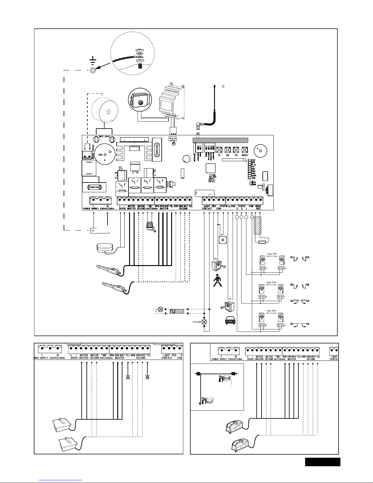
5/16 cz
PIPOJOVACÍ DIAGRAM
LYN/SCS
230VAC
PE
PE
Model
203285
Ω
8.2
+
+
+
+
+
+
+
Relay
+++
+
-
RED
RED
BLUE
BLUE
Model
CM475
BROWN
GREEN
WHITE
BROWN
GREEN
WHITE
YELLOW
YELLOW
RADIO MODULE
Model
207399
230 VAC
50
RED
RED
BLUE
BLUE
BROWN
GREEN
WHITE
BROWN
GREEN
WHITE
not required
not required
RED
RED
BLUE
BLUE
BROWN
GREEN
WHITE
BROWN
GREEN
WHITE
YELLOW
YELLOW
ART
SUB
Closed position
Open position
bateriové
Page 79
FUNKCE TLAÍTEK P1, P2, P3 & RESET
P1+P2+P3
P1
P1 + P2
P2 + P3
P1 + P3
P2
P3
DIP „RADIO“ + P1
DIP „RADIO“ + P2
RESET
Samostatný provoz. Kídly lze pohybovat samostatn. Aktivace funkce: Stisknte souasn P1 + P2 + P3. LED dioda LEARN
bliká, dokud je funkce aktivována. Tlaítko P1 uvádí v pohyb motor 1. Tlaítko P2 uvádí v pohyb motor 2. Deaktivace funkce:
Vykejte 20 sekund nebo odpojte ídicí jednotku. Pokud se kídla nejprve zavou, vymte ervený a modrý kabel.
Automaticky naprogramuje koncové polohy dráhy.
Automaticky naprogramuje koncové polohy dráhy (a dodatené polohy, nap. mkký start a mkké zastavení).
Prodleva elektronického zámku
Nastavení prodlevy kídel
Automatické zavení. Pro potvrzení je potebné tlaítko P2
Softwarový reset na výrobní nastavení. Držte tlaítko stisknuté po dobu 10 sekund. Reset se netýká bezdrátové pamti
(viz dálkové ovládání)
Programování dálkových ovlada pro kanál 1. Signál pro oba pohony (kídla)
Programování dálkových ovlada pro kanál 2. Signál pro jeden pohon (motor 1).
Naprogramování internetového rozhraní nebo kontroly vrat: Upozornní: Tlaítko RESET neprovede u tohoto ídicího
systému reset na tovární nastavení Slouží pouze k programování internetového rozhraní nebo kontroly vrat.
Viz popis tlaítka P3 pro reset na tovární nastavení.
Tlaítko Funkce
6/16 cz
POPIS SVOREK
POPIS FUNKCE
L Pipojení L pívod 230 V (fáze)
N Pipojení N pívod 230 V (nulák)
30VDC Pipojení bateriové
Motor MASTER Motor 1 (Hlavní, otevírá jako první)
Motor SECOND Motor 2 (Druhý, otevírá jako druhý)
Pro kontrolu správné polarity viz ást
„Základní nastavení“ a „Funkce tlaítek P1, P2, P3 & RESET“
24 V / 150 mA Výstražná svtelná signalizace (píslušenství)
MASTER Motor1
BRN Hndý kabel
GRN Zelený kabel
WHT Bílý kabel
YEL Žlutý kabel
SECOND Motor 2
BRN Hndý kabel
GRN Zelený kabel
WHT Bílý kabel
YEL Žlutý kabel
Light Contact Sledování brány / zahradní osvtlení
PED Pipojení pro nouzové vypnutí nebo...
COM Negativní
STOP ..vícepolohový spína
“Symbol klíe” Uzamykatelný vypína
COM Negativní
PHOTO 3 Svtelná závora 3
PHOTO 2 Svtelná závora 2
PHOTO 1 Svtelná závora 1
COM Negativní
EDGE nepímý konektor s 8,2 kiloohmy
8,2 kiloohm
“Symbol” el. zámkuVstup elektrického zámku
“vstup ídicí elektroniky”
VSTUP 24 VAC Vstupní naptí 24 V z transformátoru
Mže být zapojeno s libovolnou polaritou
Transformátor 230 VAC Pívod 230V k transformátoru
Mže být zapojeno s libovolnou polaritou.
250 V/2 A Pojistka 250V/2A (rychlospouštcí 2x)
POPIS LED (SVTELNÝCH DIOD)
Popis Barva Funkce
STOP Zelená Nouzové vypnutí
ZAP: Nouzové vypnutí aktivní
VYP: OK (drátové pemostní, pokud
není pipojen spína)
EDGE Zelená Nepímý konektor 8,2 kiloohm
ZAP: aktivováno
VYP: OK (pemostní s odporem 8,2 kohm,
pokud není pipojen nepímý konektor)
“Symbol klíe” ervená Uzamykatelný vypína
Svítí: Vypína v innosti
Nesvítí: Vypína není v innosti
PED ervená Klíový spína 1kídlový
ZAP: Spína stisknut
VYP: Spína nestisknut
PHO1 ervená Svtelná závora 1
Svítí: OK (aktivní)
Nesvítí: není pipojena žádná svtelná
závora
PHO2 ervená Svtelná závora 2
Svítí: OK (aktivní)
Nesvítí: není pipojena žádná
svtelná závora
PHO3 ervená Svtelná závora 3
Svítí: OK (aktivní)
Nesvítí: není pipojena žádná
svtelná závora
LEARN Žlutá Stav programu “uení”
Svítí: Program “uení” je aktivní
VYP: Bez programu “uení”
DGN ervená Diagnostický program
(viz “asto kladené dotazy”)
CH1 ervená Programování dálkových ovlada
pro 2kídlový provoz
ZAP: Lze naprogramovat nový
runí dálkový ovlada
VYP: Funkce vypnuta
CH2 ervená Programování dálkových ovlada
pro 1kídlový provoz (viz CH1)
Page 80

7/16 cz
PÍSLUŠENSTVÍ (VIZ PIPOJOVACÍ DIAGRAM)
FUNKNÍ ÍZENÍ (VOLITELNÝ) MODEL: TX2EV, TX4EV, TX4UNI (dálkový ovlada),
747EV (rádiový kódový zámek), 128EV (dvoukanálová rádiová nástnná tlaítka)
VÝSTRAŽNÁ SVTELNÁ SIGNALIZACE (VOLITELNÝ) MODEL: FLA24-2, FLA1-LED
K ídicí elektronice lze pipojit výstražný svtelný maják (pípojky: 24 VDC / 150 mA). Jeho funkcí je výstraha osob ped pohybující se bránou.
Výstražná svtelná signalizace musí být umístna co nejvýše a musí být jasn viditelná. ídicí elektronika generuje konstantní signál a zaízení
výstražné svtelné signalizace jej mní v blikání.
KLÍOVÝ SPÍNA (VOLITELNÝ) MODEL: 100010, 100027, 100034, 100041
Zaízení lze provozovat pomocí klíového spínae. (pípojky: Symbol klíe / COM)
Viz také pod popisem nastavení DIP spína „OPEN/PED“
SPÍNA NOUZOVÉHO VYPNUTÍ / ZASTAVENÍ (VOLITELNÝ) MODEL: 600084
Na tento výstup lze pipojit nouzový vypína, který vrata zastaví v každém smru (pípojky: STOP / 8.2 kOhm).
BEZPENOSTNÍ LIŠTA (VOLITELNÝ) MODEL: 600046, 600053, 600077, 600060
(DIP spína LOOP/EDGE musí být vyp )
K elektronickému ízení lze pipojit bezpenostní lištu (pípojky: STOP / 8.2 kOhm), která funguje na principu 8,2 K Ohm. To znamená, že na
konci bezpenostní lišty je instalován zkušební odpor vtší o 8,2 K Ohm. Ten zaruuje neustálou kontrolu proudového obvodu. ídicí elektronika
je dodána s vestavným odporem 8,2 K Ohm. Vtší množství bezpenostních lišt je pipojeno sériov. Viz také pod popisem nastavení DIP spína
„STOP/8,2 kOhm“.
SVTELNÉ ZÁVORY (VOLITELNÝ) MODEL 771E, 772E:
Doporuujeme používání svtelné závory. Použijte model 771E nebo 772E, který je také souásti sady bezpenostního píslušenství APLUS-EV.
SAFETY ACCESSORY KIT (VOLITELNÝ): APLUS-EV
ízení je již vybaveno standardní anténou. Pro vtší dosah lze pipojit externí anténu z píslušenství APLUS-EV (obsahuje svtelnou závoru 771E,
majáek FLA1-LED a externí anténu SWG-ANT-EV), jak je zobrazeno v pehledovém schématu pipojení.
myQ (VOLITELNÝ)
(pouze s internetovým rozhraním 828EV):
Umožuje ovládání vrat pes Internet nebo chytrý telefon.
KONTROLA VRAT (VOLITELNÝ)
(pouze s kontrolním zaízením vrat 829EV):
Umožuje optickou a akustickou kontrolu polohy vrat. Vrata lze prostednictvím tohoto zaízení i zavít.
BATERIE (VOLITELNÉ VYBAVENÍ)
Pípojky slouží k nabíjení externí baterie.
V pípad výpadku energie napájí baterie pohon. Pln nabitá baterie mže dodávat energii po dobu delší než 24 h. Baterie podléhají procesu
stárnutí a ztrácejí kapacitu. Podle etnosti používání baterie ji každé 2-3 roky vymte.
ELEKTRICKÝ ZÁMEK (VOLITELNÉ PÍSLUŠENSTVÍ)
ídicí elektronika nabízí možnost používat elektrický zámek (12 V). (Návod je piložen k elektrickému zámku.)
K hlavní ídicí elektronice musí být pipojena pomocná ídicí elektronika pro elektrický zámek. Pokud elektronický zámek kvli píliš velkému
tlaku brány neotevírá, lze naprogramovat speciální funkci: Stisknte souasn P2 a P3 na dobu 5 sekund a poítejte slyšitelná cvaknutí.
1 cvaknutí = cca 4 sekundy proud k elektronickému zámku (výrobní nastavení)
2 cvaknutí = brána se na jednu sekundu zave a pak oteve. Dále, po dosa ení zavené polohy brány, pohon je t krátce pracuje, aby se
dosáhlo zaklapnutí elektronického zámku brány. Upozornní: Brána musí být vybavena podlahovými dorazy.
SLEDOVÁNÍ BRÁNY NEBO OSVTLENÍ (VOLITELN)
Pipojení mají dv funkce v závislosti na tom, zda je DIP spína Light / Spy zap nebo ne. Viz také oddíl „NASTAVENÍ DIP SPÍNA“ v tomto návodu.
Výstup nedisponuje ádným vlastním napájením a smí být zatí en max. do 24 V.
Kontrola vrat / stav vrat (Spy)
Na svorky lze zapojit LED diodu, svtlo (24 V / 3 W max.) nebo relé pro indikaci stavu vrat.
LED dioda nesvítí = vrata jsou zavená
LED dioda pomalu bliká = vrata se otevírají
LED dioda svítí = vrata jsou otevená
LED dioda rychle bliká = vrata se zavírají
Osvtlení dvora / osvtlení na 120 sekund
Na svorky lze zapojit svtlo (24 V / 3 W max.) nebo relé.
Pokud ízení dostane signál pro otevení nebo zavení vrat, svítí svtlo po dobu 120 sekund a poté se automaticky vypne.
POZOR: Výstup lze zatí it max. 24 V nebo musí být pedazeno relé.
Page 81
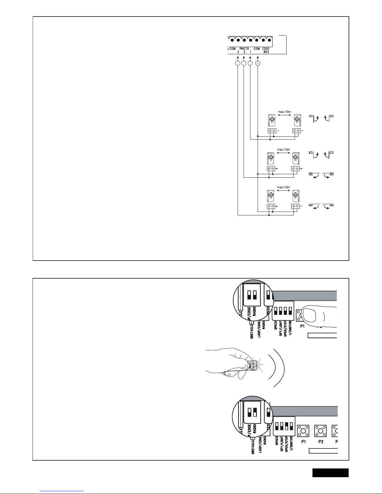
8/16 cz
SVTELNÉ ZÁVORY (VOLITELNÉ PÍSLUŠENSTVÍ) 771E, 772E
Svtelné závory slouží k zabezpeení brány a je nezbytné je používat. Výbr místa
jejich instalace závisí na konstrukci brány. Podle normy EN12453 musí být venku
instalována dvojice svtelných závor aktivních pi „zavírání“ ve výšce 200mm.
Svtelné závory se skládají z vysílae a pijímae, které musí být položeny naproti
sob. Svtelnou závoru instalujte na ze pomocí hmoždinek a malých šroub. Pokud
chcete mít možnost použití funkce “automatického zavírání”, je nezbytné instalovat
svtelnou závoru Chamberlain – Failsafe. Systém Chamberlain – Failsafe (systém se
2 kabely) je na obou stranách vybaven malou diodou LED (kontrolka) viditelnou
zvení. Ta indikuje stav svtelné závory.
Naprogramování svtelné závory:
- pipojte svtelnou závoru
- provete naprogramování dráhy kídel brány.
Vymazání svtelné závory z ídicí jednotky:
Pipojenou svtelnou závoru nelze odstranit bez toho, aby ídicí jednotka nezastavila
funkci na píslušném pipojení. Pro smazání svtelné závory z programu ídicí jednotky.
- odstrate svtelnou závoru
- krátce vypnte proud
- provete naprogramování dráhy kídel brány.
Diagnostika svtelné závory Chamberlain-Failsafe
LED konstantní = OK
LED bliká = svtelná závora blokuje ídicí elektroniku
LED nesvítí = není proud, nesprávn provedené pipojení nebo nesprávné pólování
Diagnostika ídicí elektroniky
LED nesvítí = OK, není pipojena žádná svtelná závora
LED bliká = elektronické ízení blokováno
Pípojka 1 & COM
Aktivní, když se brána zavírá (provádí zptný pohyb)
Pípojka 2 & COM
Aktivní, když se brána zavírá nebo otevírá
Pípojka 3 & COM
Aktivní, když se brána otevírá
(brána zstane bez pohybu tak dlouho, dokud se pekážka
neodstraní z oblasti infraerveného paprsku, poté brána dokoní pohyb)
RÁDIOVÝ MODUL
PROGRAMOVÁNÍ/VYMAZÁVÁNÍ DÁLKOVÝCH OVLÁDANÍ
Pijíma má 2 kanály CH1 a CH2. Používání obou kanál umožuje
jak jednokídlový, tak i dvojkídlový provoz. Píklad: Pokud dostane
CH2 = P2 signál od dálkového ovládání, oteve se pouze 1 kídlo.
Pokud použijete další tlaítko dálkového ovládání CH1 = P1, otevou
se ob kídla.
PROGRAMOVÁNÍ
1: Zapnout DIP spína „RADIO“.
2: Stisknte krátce tlaítko P1 (pro CH1) nebo P2 (pro CH2) a píslušná
LED dioda se rozsvítí.
3: Podržte nyní požadované tlaítko na vašem dálkovém ovládai stisk
nuté, dokud LED dioda po krátkém blikání nezhasne. A hotovo! Zopakuj
te tyto kroky pro všechny dálkové ovladae (maximáln lze naprogramo vat 85/ kanálu dálkových ovlada).
Dležité: Po naprogramování vašeho dálkového ovladae (dálkových
ovlada) opt odpojte vypnout DIP spína “RADIO”!
Upozornní: Ujistte se, že nebylo zaueno stejné tlaítko vašeho dálkového
ovladae na CH1 a CH2, jinak zaízení nebude správn fungovat.
MAZÁNÍ
- Zapnout DIP spína „RADIO“
- Podržte tlaítko P1 stisknuté tak dlouho, pokud svítící LED dioda po asi
10 sekundách nezhasne. A hotovo!
Pro potvrzení zablikají ob LED diody CH1 a CH2 8krát.
- Vypnout DIP spína „RADIO“
RADIO MODUL
E
ON ON
RADIO MODUL
E
ON ON
RA
ON ON
RA
ON ON
+
+
+
+
+
+
+
+++
Page 82
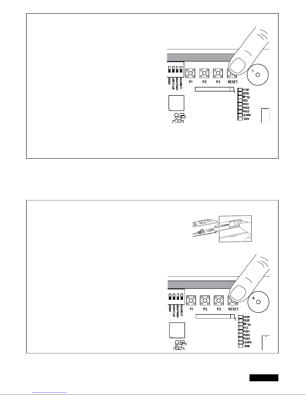
9/16 cz
NAPROGRAMOVÁNÍ INTERNETOVÉHO ROZHRANÍ myQ
Prostednictvím tlaítka RESET na ízení
1. Internetové rozhraní od spolenosti Liftmaster a váš router propojte se
síovým kabelem.
2. Zapnte napájení internetového rozhraní od spolenosti Liftmaster.
3. Zite si nový online úet prostednictvím nejnovjší aplikace myQ pro chytré
telefony od spolenosti Liftmaster nebo na www.liftmaster.eu.
4. Zaregistrujte si internetové rozhraní od spolenosti Liftmaster.
5. Kliknte na „Pidat nové zaízení“ a dále postupujte podle krok aplikace nebo
webové stránky.
6. Upozornní: Pokud stisknete tlaítko RESET, uslyšíte pípnutí a LED diody
CH1 a CH2 se nejprve rozsvítí a poté, po úspšné synchronizaci, tikrát
bliknou a zhasnou.
7. Aplikace takto indikuje, zda bylo programování úspšné a vyzve vás k zadání
názvu vrat.
NAPROGRAMOVÁNÍ KONTROLY VRAT
Prostednictvím tlaítka RESET na ízení
1. Zapojte napájení kontrolního zaízení vrat a v domu je umístte tak, aby bylo
dobe viditelné. Pokud je místo montáže píliš vzdáleno od vrat, mže být
spojení rušeno nebo se asto perušovat. Umístte zaízení na lépe vhodné
montážní místo.
2. Krátce stisknte a puste tlaítko „LEARN“ na zadní stran kontrolního
zaízení vrat. Stídav bliká ervená a zelená LED dioda. Bhem 60 s stiskn
te a puste tlaítko RESET na ízení. Pro potvrzení naprogramování se ro
zsvítí ervená a zelená LED dioda.
Vymazání kontroly vrat
Podržte alespo po dobu 10 s stisknuté tlaítko „LEARN“ na zadní stran kont-
rolního zaízení vrat.
Krátké pípnutí potvrdí úspšné vymazání.
ADIO MODULE
ADIO MODULE
Page 83
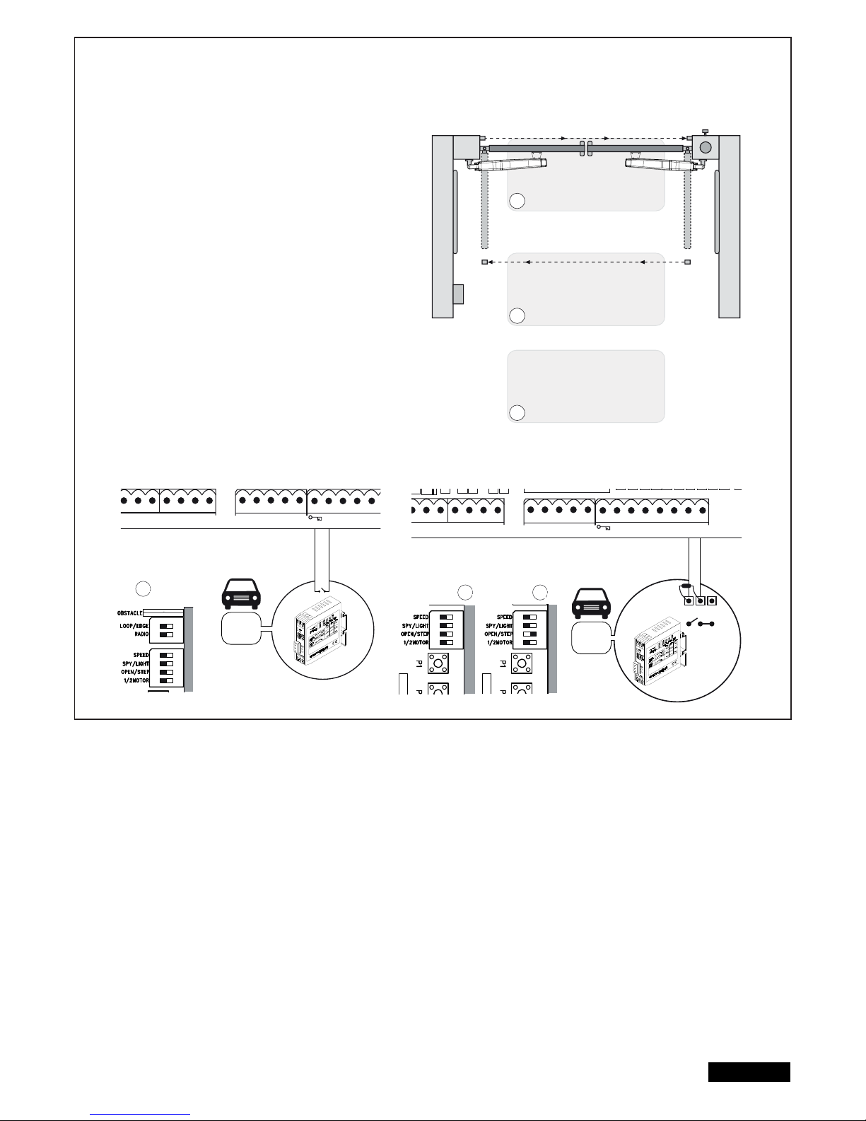
SMYKOVÉ DETEKTORY
(DIP spína LOOP/EDGE musí být zapojen.)
Smykové detektory reagují na kov a používají se vtšinou k
rozpoznávání osobních a nákladních automobil, ale nikoli
motocykl a chodc.
Výstupní smyka A
Výstupní smyka se nachází za branou a otvírá bránu, pokud je
zavená, drží ji otevenou nebo ji otvírá znovu.
DIP spína OPEN/STEP + LOOP/EDGE musí být zap.
Svtelné závory musí být pipojeny a funkce
„Automatické zavení“ musí být aktivována.
Bezpenostní smykový detektor a
smykový detektor v dosahu pohybu brány B,C
Smykové detektory slouží k rozpoznávání vozidel (osobních a
nákladních automobil), ale jako jediné ochranné opatení jsou
nepípustné, protože nerozpoznávají osoby.
Vyhodnocovací jednotka smykových detektor se pipojuje jako
generátor signálu s kontaktem NO (bžn oteveno)
na svorky 8,2kiloohmového nepímého konektoru.
Pokud chcete použít také nepímé konektory:
Ped instalací vyzkoušejte, který zpsob fungování je pro n vhodný.
Bezpenostní smykový detektor
=> DIP spína OPEN/STEP musí být zap.
Smykový detektor v dosahu pohybu brány
=> vypnout DIP spína OPEN/STEP
Dal í mo nosti smykových detektor lze poptat u na eho servisního
oddlení.
10/16 cz
RN WHT YEL
ASTER
BRN GRN WHT YEL
SECOND
COM
PHOTO
3 2 1
C
LIGHT
CONTACT
PED
COM
STOP
NO
Model
203292
Model
203292
RN WHT YEL
ASTER
BRN GRN WHT YEL
SECOND
COM
PHOTO
3 2 1
COM EDGE
8.2KΩ
LIGHT
CONTACT
PED
COM
STOP
NO
COM
NC
A
B
C
A
B C
RADIO
ON ON
RADIO
MOD
ON
RADIO
MOD
ON
Page 84
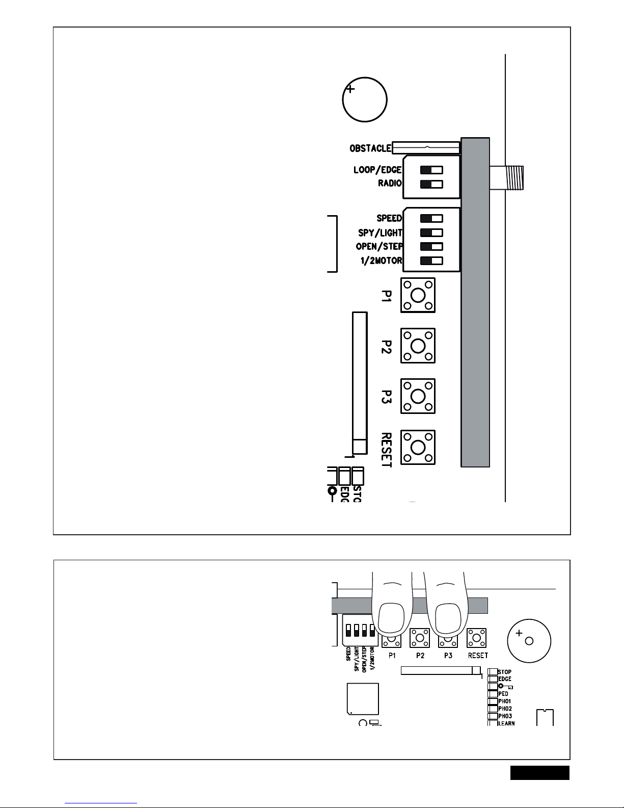
NASTAVENÍ DIP SPÍNA
1 / 2 MOTORY
Vybere, zda je k ídicí jednotce pipojen 1 motor nebo 2 motory
VYP: 2 motory pipojeny
ZAP: 1 motor pipojen
OPEN/STEP
Zmní naprogramování a reakci ídicí jednotky na signály.
Pro použití se smykovými detektory si prosím nejprve pette oddíl
„Smykové detektory“. Krokový režim: První signál bránu oteve, další
zastaví, další zave, další zastaví, další oteve atd. ...
Režim otevírání: Brána nebude reagovat na signály ídicí jednotky,
dokud se otevírá a dokud nedosáhne polohy OTEVENO.
VYP: Krokový režim
ZAP: Režim otevírání
LIGHT/SPY
Zapnout pouze, pokud je funkce potebná, jinak ponechte vyp.
VYP: LIGHT
ZAP: SPY
OBSTACLE
Z výroby vybaveno pevným drátným pemostním. Peru ení zvy uje
pracovní sílu na ízení.
POZOR: Pokud je drátné pemostní peru eno, musí být brána zaji
tna dodatenými bezpenostními zaízeními (kontaktní li tou atd.).
LOOP/EDGE
Zvolte požadovanou funkci
VYP: Nepímý konektor
ZAP: Smykový detektor
SPEED
Vyberte pro typ motoru, který chcete použít.
VYP: ART
ZAP: LYN, SCS, ART, SUB
RADIO
K naprogramování runích dálkových ovlada je nutný DIP spína
„RADIO“. Postup naprogramování naleznete v píslušném
oddílu tohoto návodu.
VYP: není možné naprogramování
ZAP: programování je možné
DLEŽITÉ: Vypnout DIP spína „RADIO“
nepoužíváte, vždy jej odstrate.
PRODLEVA KÍDEL
Prodleva kídel je potebná ke správnému a bezpenému otevení a
zavení kídel. Delší prodleva kídel mže být nutná pi rzných
pípadech instalace nebo pi rzných délkách kídel.
Stisknte a držte zárove P3 a P1 po dobu cca 5 sekund a poítejte
poet slyšitelných cvaknutí.
Cvakání je zpsobováno relé (svtelným relé).
1 cvaknutí = krátké zpoždní, cca 4÷8 sekund (tovární nastavení)
2 cvaknutí = stedn dlouhé zpoždní, cca 8÷12 sekund
3 cvaknutí = dlouhé zpoždní, cca 12÷16 sekund
4 cvaknutí = úplné zpoždní, kídlo 1 se zave teprve tehdy, když je
kídlo 2 zcela zaveno
Zpoždní pi otevírání je vždy cca 3÷5 sekund
5 cvaknutí = žádné zpoždní, ob kídla se otevírají a zavírají souasn
V pípad nutnosti postup zopakujte.
UPOZORNNÍ: Naprogramování (zmna) dráhy vrátí
prodlevu kídel zpátky na výrobní nastavení.
11/16 cz
RADIO MODULE
RADIO MODULE
ON ON
Page 85
12/16 cz
PRVNÍ UVEDENÍ DO PROVOZU
ZÁKLADNÍ NASTAVENÍ
Postupujte pesn bod po bodu. Pokud máte pochybnosti, zante znovu od zaátku. Rezervujte si pro provedení nastavení dostatek asu.
1. Jsou pipojeny všechny souásti potebné k provozu? Motory, svtelné závory, bezpenostní lišty, vypína.
2. Zajistte, aby se nikdo nezdržoval ani nemohl zdržovat v oblasti brány.
3. Zavete bránu a zavste motory. Zajistte motory epy se závlakami a otote odjišovací páku ve smru branového sloupku.
Pohony jsou zajištny.
ART:
- pro úspšné naprogramování dráhy musí být nastaveny referenní
body. K tomu musí být správn nastaveny vaky pod krytem ART.
Nejprve má mikrospína aktivovat horní vaka, pak spodní.
Mikrospínae nemají být aktivovány souasn a rovnž nemají být
aktivovány, pokud brána dosáhla koncových bod. Vyšroubujte vaky
pomocí kleští nebo velkého plochého šroubováku.
- pro tato nastavení bránu odblokujte
- kontrola nebo oprava správné polohy vakových spína, jak je uvedeno
v návodu pro OTEVENÍ a ZAVENÍ brány.
- nastavení DIP spína pi použití ART: vypnout DIP spína
„SPEED“. ART nebude fungovat, pokud je „SPEED“ zap.
SUB (podpodlažní pohon):
nastavení DIP spína: spína „SPEED“ zap pro rychlejší pohyb brány nebo vyp, pokud je brána píliš tžká nebo pokud je nutný
velmi bezpený provoz. Lze ho po dokonení instalace kdykoliv zmnit.
LYN / SCS:
Nastavení DIP spína: spína „SPEED“ zap pro rychlejší pohyb brány nebo vyp, pokud je brána píliš tžká nebo pokud je nutný
velmi bezpený provoz. Lze ho po dokonení instalace kdykoliv zmnit.
Nyní pipojte ídicí elektroniku k elektrické síti.
ZÁKLADNÍ NASTAVENÍ:
1. Stisknte souasn tlaítka P1, P2 a P3 po dobu 2-3 sekund, dokud nezane blikat žlutá LED.
2. Pozorujte bránu. Stisknte a podržte tlaítko P1stisknuto po dobu 1-2 sekund. Brána s motorem 1 se pitom musí pohybovat smrem k
poloze OTEVENO. (Bránu neotvírejte zcela, jen s ní krátce popojete.) Pokud motor 1 místo otevírání uzavírá, je špatn pipojen a kabely
ervený/modrý v motoru musí být vymnny. (Pozor: Odpojte pedtím ídicí elektroniku ze sít!)
Upozornní: Obecná funkce - uvolníte-li tlaítko, brána se ihned zastaví. Pi optovném stisknutí se brána pohybuje v opaném smru, dokud opt
neuvolníte tlaítko atd.
3. Stisknte a podržte tlaítko P2 po dobu 1-2 sekund. Brána s motorem 2 se pitom musí pohybovat smrem k poloze OTEVENO. (Bránu
neotvírejte zcela, jen s ní krátce popojete.) Pokud motor 2 místo otevírání uzavírá, je špatn pipojen a kabely ervený/modrý v motoru musí
být vymnny. (Pozor: Odpojte pedtím ídicí elektroniku ze sít!)
Upozornní: V tomto manuálním nastavení programu zstává ídicí elektronika 20 sekund. Zante pípadn znovu od zaátku souasným
stisknutím tlaítek P1/P2/P3.
Zkontrolujte:
1. Pouze u pohon SCS: Pokud se kídlo otvírá, NESMÍ se pední výstupek motoru dotknout brány (narazit do ní nebo se o ni otít). Otevení
nkolikrát perušte a zkontrolujte! V pípad dotyku se musí zkontrolovat rozmry A/B a pípadn podložit závs brány za úelem dosažení
vtší vzdálenosti.
2. Ob kídla zcela otevete. Nezajete píliš daleko! Pokud v otvírací pozici není k dispozici žádný doraz, vyznate maximální bod otevení.
3. Pouze u SUB (podpodlažního pohonu): Nyní nastavte mechanické koncové dorazy ve skíni. Pokejte, až “uební” LED sama zhasne
(20 sekund od posledního stisknutí tlaítka).
Closed position
Open position
ZAVENÍ brány
OTEVENÍ brány
Page 86

13/16 cz
PROGRAMOVÁNÍ DRAH POHYBU: JEDNODUCHÉ I
Upozornní: Musí být namontovány dorazy pro OTEVENOU a ZAVENOU polohu.
1. Kídla musí být zavena.
2. Stisknte tlaítko P1, dokud se kídlo / motor 1 nezane otevírat. (bliká led “LEARN /UENÍ”.)
Zaíná automatický program (pomalý pohyb):
Kídlo 1 se posouvá k dorazu v poloze OTEVENO.
Kídlo 2 se posouvá k dorazu v poloze OTEVENO.
Pak se kídlo 2 posouvá k dorazu ZAVENO a nakonec se kídlo 1 posouvá k dorazu ZAVENO.
Programování je ukoneno, když zhasne LED “LEARN/UENÍ”.
Upozornní: Zavírají-li se kídla, místo aby se otvírala, pak jsou špatn zapojeny motory. Zamte ervenou a modrou.
PROGRAMOVÁNÍ DRAH POHYBU: JEDNODUCHÉ II
Upozornní: Pokud není ve smru OTEVENO žádný koncový doraz, mlo by kídlo být zastaveno v úhlu otevení pibližn 90o.
1. Kídla musí být zavena.
2. Stisknte tlaítko P1, dokud se kídlo / motor 1 nezane otevírat.
3. Stisknte tlaítko P1 “hluboce stisknout” 1x, když kídlo / motor 1 dosáhne polohu OTEVENO. Kídlo 2 zahájí pohyb.
4. Stisknte tlaítko P1 “hluboce stisknout” 1x, když kídlo / motor 2 dosáhne polohu OTEVENO. Kídlo 2 se pak automaticky zave. Potom se
automaticky zave kídlo 1.
5. Pohon se automaticky nauí polohu brány ZAVENO.
Na pání však mžete také “nauit” vlastní bod pro polohu ZAVENO.
Stisknte tlaítko P1 “hluboce stisknout” pro každé kídlo na míst požadované polohy ZAVENO.
Programování je ukoneno, když zhasne LED “LEARN/UENÍ”.
PROGRAMOVÁNÍ DRAH POHYBU “ADVANCED” (“POKROILÉ” - VLASTNÍ)
Upozornní: U tohoto programu musíte stisknout tlaítko P1 celkem devtkrát.
Pi každém stisknutí tlaítka je uložena jedna poloha (as). Tak je možné uložit funkci soft-stop (pomalý chod) a individuáln ji pizpsobit
brán nebo zpsobu použití. Jsou možné dlouhé nebo krátké fáze funkce soft-stop.
1. Kídla musí být zavena.
2. Souasn stisknte tlaítka P1 a P2 po delší dobu (pibližn 5-6 sekund), dokud se neaktivuje (neotvírá) kídlo 1. Uvolnte tlaítka!!
3. Znovu stisknte tlaítko P1. Funkce soft-stop pi OTEVÍRÁNÍ pro kídlo 1 zaíná od této polohy.
4. Znovu stisknte tlaítko P1. Bude dosaženo koncového dorazu OTEVENO. Nyní se automaticky aktivuje kídlo 2.
5. Znovu stisknte tlaítko P1. Funkce soft-stop pi OTEVÍRÁNÍ pro kídlo 2 zaíná od této polohy.
6. Znovu stisknte tlaítko P1. Bude dosaženo koncového dorazu OTEVENO. Nyní se automaticky aktivuje a zavírá kídlo
7. Znovu stisknte tlaítko P1. Funkce soft-stop pi ZAVÍRÁNÍ pro kídlo 2 zaíná od této polohy.
8. Znovu stisknte tlaítko P1. Bude dosaženo koncového dorazu ZAVENO. Nyní se automaticky aktivuje kídlo 1.
9. Znovu stisknte tlaítko P1. Funkce soft-stop pi ZAVÍRÁNÍ pro kídlo 1 zaíná od této polohy.
10. Znovu stisknte tlaítko P1. Bude dosaženo koncového dorazu ZAVENO. ->Hotovo
Upozornní: Dosáhne-li jedno kídlo koncového dorazu a tlaítko L1 NEBUDE stisknuto, najede pohon na doraz a nauí se samostatn tuto polohu.
Page 87
14/16 cz
DOKONENÍ INSTALACE/PROGRAMOVÁNÍ:
Po naprogramování dráhy pohybu, mohou být “ueny” dálkové ovládae. (Viz NATENÍ FUNKCÍ/ VYMAZÁNÍ FUNKCÍ DÁLKOVÉHO OVLÁDAE.)
1. Provete testovní chod brány tak, e stisknete tlaítko runího ovladae nebo pipojeného tlaítka, nechejte probhnout 2 kompletní cykly a
sledujte prbh. Opt bránu zavete, ANI byste provedli dal í nastavení.
2. Jakmile jsou všechna nastavení hotová, zkontrolujte funknost svtelných závor, tlaítek, výstražné svtelné signalizace, dálkových ovláda,
píslušenství atd.
3. Ukažte všem osobám, které budou bránu obsluhovat, jak pohyb brány probíhá, jak fungují bezpenostní funkce a jak lze bránu odjistit a ovládat
manuáln.
Automatické zavírání brány
Upozornní: Lze použít jen s pipojenou a funkní svtelnou závorou (1+COM). Dobu automatického zavení je možno zvolit v rozmezí
2 až 120 sekund.
Nastavení
1. Stisknte a podržte P2, dokud nezane blikat žlutá LED.
2. Když žlutá LED bliká, odpoítejte dobu otevení, která má být naprogramována.
3. Po uplynutí požadované doby stisknte optovn P2. ->Hotovo
Vypnout
1. Stisknte a podržte P2, dokud nezane blikat žlutá LED.
2. Stisknte P3. Žlutá LED zhasne. ->Hotovo
PRACOVNÍ SÍLA POHONU
Pracovní síla pohonu bude nastavena automaticky bhem
programování dráhy pohybu. Zmna (automatická) je možná jen
novým programováním dráhy pohybu. Vzpiuje-li se brána vlivem
povtrnostních vliv nebo zmn samotné brány (nap. rezavní nebo
nedostatené mazání), musí být pípadn opravena.
ídicí elektronika spluje aktuální požadavky smrnic
evropských norem (EN). Jedna z tchto smrnic vyžaduje, aby
na posledních 500 mm ped uzavením nepesáhla síla na hran
brány hodnotu 400 N (40 kg). Ve vzdálenosti vtší než 500 mm smí
maximální síla dosahovat na hran brány hodnoty 1400 N (140 kg).
Pokud nelze tyto podmínky zajistit, je bezpodmínen nutné v
daném pípad instalovat bezpenostní lištu na brán do výšky 2,5
m nebo na protilehlý sloupek (EN12453).
LIKVIDACE
Obal se skládá z materiál, které neohrožují životní prostedí. Lze jej vyhodit do kontejner pro recyklaci v míst bydlišt. Podle smrnice
EU 2002/96/ES o odpadních elektrických a elektronických zaízeníchmusí být tento pístroj po použití ádn zlikvidován, aby byla zajištna
recyklace použitých materiál.
O možnostech takovéto likvidace informuje správa obcí a mst.
LIKVIDACE BATERIÍ
Baterie a akumulátory nesmí být likvidovány v rámci domácího odpadu.
Po použití mžete baterie bezplatn vrátit ve vaší bezprostední
blízkosti (nap. v obchod nebo ve sbrnách komunálního odpadu).
Baterie a akumulátory jsou oznaeny peškrtnutou nádobou na odpad
a také chemickým symbolem škodlivé látky, totiž “Cd” pro kadmium,
“Hg” pro rtu a “Pb” pro olovo.
12VDC
Pb Cd Hg
Page 88

15/16 cz
DIAGNOSTICKÁ LED DIODA
Diagnostická LED dioda signalizuje chybu, která se vyskytla nejdíve. Pokud by se vyskytly další chyby, je možné, že nebudou signalizovány.
Signál
1 x blikne
2 x blikne
3 x blikne
4 x blikne
5 x blikne
6 x blikne
7 x blikne
8 x blikne
9 x blikne
10 x blikne
11 x blikne
12 x blikne
13 x blikne
14 x blikne
15 x blikne
Popis
Pohon 1 Chyba kontaktu jednoho z kabel k ídicí
elektronice.
Jako 1x blikne pro pohon 2.
Koncové body pohonu 2 nebyly akceptovány.
A: Po nebo pi funkci uení: Pohon 1 nebyl dost daleko oteven
B: Chyba kontaktu jednoho z kabel k ídicí elektronice. Žlutý
nebo bílý kabel nemá kontakt nebo je kontakt špatný.
Koncové body pohonu 1 nebyly akceptovány.
V ídicí elektronice není naprogramována dráha pohybu.
Síla potebná pro pohyb kídla je píliš vysoká.
A: Brána je vadná.
B: Brána má tžký chod.
C: Brána se pi vtru zastavuje.
Svtelná závora 1 blokuje funkci.
A: Objekt blokuje svtelnou závoru.
B: Vzájemné nastavení oek není pesné.
C: Svtelné závory nemají dostatek naptí.
Svtelná závora 2 blokuje funkci.
Svtelná závora 3 blokuje funkci.
Nouzový vypína blokuje zaízení.
Bezpenostní lišta blokuje zaízení.
A: Objekt tlaí na bezpenostní lištu.
B: Bezpenostní lišta je vadná.
C: Dodávané naptí je píliš nízké nebo došlo ke zlomení
kabelu v pívodu.
Hodnota proudu pivádného k ídicí elektronice je píliš nízká.
A: Vadné vedení 230 V nebo špatné kontakty.
B: Zlomení kabelu v pívodu (tuhý mdný kabel).
C: Baterie, dodávaná jako píslušenství a umožující
provoz pi výpadku proudu, je prázdná.
Chyba EEPROM
Zatížení ídicí elektroniky se nezdailo.
Pouze u pohon LYN/SCS
Motor je ješt odblokován
Závada na relé nebo na jiné dležité
elektronické souásti
A: Peptí
B: špatná kabeláž (chybná)
D: silná vlhkost ve svtelné závoe (nedokonalá
instalace)
E: svtelná závora byla pedtím pipojena, ale
nebyla odstranna (odpojena)
ešení
Zelený nebo bílý kabel nemá kontakt nebo je kontakt špatný.
Co nejpelivji vyzkoušejte pípojky. Všímejte si délek vedení.
Viz 1 x blikne.
A: Otevete šíeji bránu pi “uení” – natení dráhy. Pes 50%
maximální dráhy.
B: Co nejpelivji vyzkoušejte pípojky. Všímejte si délek vedení.
Viz 3 x blikne
Opakujte funkci uení – natení koncových bod.
A: Opravte bránu.
B: Zkontrolujte lehkost pohybu brány.
C: Neprovozujte bránu pi silném vtru.
D Opakujte funkci uení - natení koncových bod, tím bude
znovu “nauena” potebná síla.
A: Odstrate.
B: Zkontrolujte.
C: Zkontrolujte prezy vedení a pípojek.
Viz 7x bliknout.
Viz 7x bliknout.
A: Zkontrolujte vedení a kabeláž.
B: Zkontrolujte základní nastavení (DIPs).
A: Odstrate.
B: Zkontrolujte vedení a kabeláž. Zkontrolujte odpor 8,2 KOhm.
C: Zkontrolujte základní nastavení (DIPs).
A: Zkontrolujte pípojky.
B: Kontrola (odborník).
C: Nechejte 24 hodin nabíjet baterie.
Nahrate ídicí elektroniku.
Zablokujte motor
Vymte ídicí jednotku
Zkontrolujte kabeláž
Znovu zaute dráhu od polohy Brána zcela uzavena
Page 89

16/16 cz
ASTO KLADENÉ DOTAZY
Žádná reakce pi stisknutí tlaítek P1, P2 a P3
Pohon vbec nereaguje, nesvítí žádná dioda
LED
Ihned poté, co se vrata zanou pohybovat, se
zastaví anebo zajedou zpt
Vrata lze pouze otevít
Nefunguje „Automatické zavení“
Elektronické ízení nereaguje na pokyny
dálkového ovladae, funguje pouze pomocí
spínae, a zde pouze pokud je tlaítko stisknuto
a podrženo.
Pohon vbec nereaguje, i když je ízení pipoje-
no. (Diody LED svítí)
ídicí jednotka nefunguje s dálkovým ovladaem
ídicí jednotka nefunguje
Pi funkci soft-stop se vratové kídlo neoteve
úpln
Sloupek vrat je tak tlustý, že nemohu dodržet
rozmry A+B.
Nelze zauit dráhu
Pohon bží krátkou dobu pomalu
Event. výpadek elektrického proudu.
Pekážka v oblasti vrat nebo mají vrata
tžký chod (pivolejte odborníka)
Svtelná závora blokuje
Elektronické ízení je zablokováno bezpe-
nostní svtelnou závorou, bezpenostní
lištou nebo vypínaem Pro OTEVÍRÁNÍ
byla pipojena pouze jediná svtelná
závora
1. Runí vysíla není naprogramován.
2. Diody LED indikují chybu.
3. Svtelná závora je nesprávn pipojená.
4. Svorka pro motory není event. správn
nasazená.
1. dálkový ovlada není naprogramovaný
2. Blokuje svtelná závora
3. DIP spína „RADIO“
Není zauena dráha
1.Pro pípad vtrného poasí je síla
nastavena na píliš nízkou hodnotu
(plnostnná vrata)
2.Vrata se pohybují ztžka
Provete vybrání sloupku vrat nebo vrata
posute.
1. Nastavení DIPs není správné
2. Chybná kabeláž nebo vadný kabel
3. viz diagnostická LED dioda
4. Bzuení v kabeláži
5. Brána se bhem naprogramování
pohybuje pouze po dobu 1 sekundy a pak
se zastaví, aniž by došlo k reverznímu
pohybu
6. Pouze u pohon ART: Nesprávné
nastavení referenních bod
7. Pouze u pohon ART: Motor je ješt
odblokován
Výpadek proudu
zapnout DIP spína „RADIO“
1. Zkontrolujte fázový a nulový vodi.
2. Zkontrolujte domovní pojistku.
Zkontrolujte, zda se v oblasti vrat nevyskytují
pekážky
Zkontrolujte svtelné závory
Naprogramujte znovu dráhu
Je nutno provit funkci a pipojení
Funguje pouze s 2kabelovou svtelnou
závorou 771E(ML) nebo 772E(ML).
Minimáln jedna svtelná závora musí být
pipojena a musí být aktivní pi ZAVÍRÁNÍ
nebo OTEVÍRÁNÍ & ZAVÍRÁNÍ.
1. Provete nauení runího vysílae.
2. Najdte a odstrate chybu (viz popis diod LED).
3. Zkontrolujte pipojení/naprogramování
svtelné závory.
4. Zkontrolujte svorku a pívody.
ad 1: Naprogramujte dálkové ovladae
ad 2: Zkontrolujte svtelnou závoru
ad 3: zapnout DIP spína
Provete zauení dráhy. Viz První uvedení do
provozu
Viz Diagnostická dioda
2.Opravte vrata tak, aby se pohybovala
zlehka
3.Programujte elektronické ízení bez
fáze soft-stop
1. V návodu si prohlédnte bod „1/2 Motor“
2. Pokud se motor pohybuje, zkontrolujte hndý,
zelený, bílý a žlutý kabel. Vyzkoušejte jiný kabel,
abyste vylouili chybu u kabelu položeného v zemi
nebo za tímto úelem na zkoušku pipojte z motoru
vycházející kabel pímo na ídicí jednotku.
3. Zkontrolujte diagnostické LED diody za úelem
zjištní chyby.
4. Viz ešení 2. Pokud je to nutné, vymte kabel.
Viz také bod „Velikosti kabelu“
5. Nedostatené napájení nebo špatná kabeláž. Viz
ešení 2
6. Správn nastavte vaky na motoru. Viz návod k
pohonu ART
7. Zablokujte pohon. Viz návod k pohonu ART
Normální postup. Pohon po výpadku proudu
neprovede test funkce. Ten trvá v závislosti na
modelu nkolik sekund nebo celý cyklus.
Neperušujte bhem funkního testu pohon
dálkovým ovladaem nebo spínaem, jinak by
se mohly posunout koncové body. V tomto
pípad pomocí P1 znovu naprogramujte dráhu.
Vyvarujte se zbytených výpadk proudu.
Je píliš malý dosah senzoru Doporuujeme instalaci venkovní antény, protože se ídicí jednotka s krátkou kabelovou anténou
ve vtšin pípad nachází za sloupkem nebo v blízkosti zem. Optimální poloha antény je vždy
co nejvýše. Spolenost Chamberlain nabízí jako píslušenství odpovídající anténu s montážní
sadou pod.
Vrata se musí pohybovat do stoupání Zmte vrata! Vrata se mohou nekontrolovan pohybovat (nebezpené), pokud je odblokovaný
pojezd. Ve smru stoupání není poteba vyšší síla; v opaném smru má pak pohon píliš mnoho
síly.
Page 90

TEMA PÁGINA
NORMAS DE SEGURIDAD . . . . . . . . . . . . . . . . . . . . . . . . . . . . . . . . . . . . . . . . . . . . . . . . . . . . . . . . . . . . . . . . . . . . . . . . . . . . .1
DATOS TÉCNICOS CONTROL DEL MOTOR . . . . . . . . . . . . . . . . . . . . . . . . . . . . . . . . . . . . . . . . . . . . . . . . . . . . . . . . . . . . . . .2
ESTRUCTURA TÍPICA DE UNA INSTALACIÓN . . . . . . . . . . . . . . . . . . . . . . . . . . . . . . . . . . . . . . . . . . . . . . . . . . . . . . . . . . . . .2
MONTAJE DE LA CAJA DE MANDO . . . . . . . . . . . . . . . . . . . . . . . . . . . . . . . . . . . . . . . . . . . . . . . . . . . . . . . . . . . . . . . . . . . . . 2
PREPARATIVOS DE LA CAJA DE MANDO . . . . . . . . . . . . . . . . . . . . . . . . . . . . . . . . . . . . . . . . . . . . . . . . . . . . . . . . . . . . . . . .2
MODO DE PROCEDER RECOMENDADO . . . . . . . . . . . . . . . . . . . . . . . . . . . . . . . . . . . . . . . . . . . . . . . . . . . . . . . . . . . . . . . . .3
CABLEADO DEL MANDO / VISIÓN DE CONJUNTO / CABLES Y CABLEADO . . . . . . . . . . . . . . . . . . . . . . . . . . . . . . . . . . . 4
ECQUEMA DE CONEXIONES . . . . . . . . . . . . . . . . . . . . . . . . . . . . . . . . . . . . . . . . . . . . . . . . . . . . . . . . . . . . . . . . . . . . . . . . . . .5
DESCRIPCIÓN / FUNCIÓN DE LAS CONEXIONES . . . . . . . . . . . . . . . . . . . . . . . . . . . . . . . . . . . . . . . . . . . . . . . . . . . . . . . . . 6
DESCRIPCIÓN DE LOS LEDS . . . . . . . . . . . . . . . . . . . . . . . . . . . . . . . . . . . . . . . . . . . . . . . . . . . . . . . . . . . . . . . . . . . . . . . . . . 6
FUNCIONES DE LOS PULSADORES P1, P2, P3 & RESET . . . . . . . . . . . . . . . . . . . . . . . . . . . . . . . . . . . . . . . . . . . . . . . . . . . 6
ACCESORIOS OPCIONALES . . . . . . . . . . . . . . . . . . . . . . . . . . . . . . . . . . . . . . . . . . . . . . . . . . . . . . . . . . . . . . . . . . . . . . . . . . .7
FOTOCELULAS . . . . . . . . . . . . . . . . . . . . . . . . . . . . . . . . . . . . . . . . . . . . . . . . . . . . . . . . . . . . . . . . . . . . . . . . . . . . . . . . . . . . . .8
MODULO DE RADIO . . . . . . . . . . . . . . . . . . . . . . . . . . . . . . . . . . . . . . . . . . . . . . . . . . . . . . . . . . . . . . . . . . . . . . . . . . . . . . . . . .8
PROGRAMACIÓN INTERFAZ INTERNET MYQ / SUPERVISIÓN DE PUERTA. . . . . . . . . . . . . . . . . . . . . . . . . . . . . . . . . . . . 9
USO DE LOS DETECTORES DE BULCE . . . . . . . . . . . . . . . . . . . . . . . . . . . . . . . . . . . . . . . . . . . . . . . . . . . . . . . . . . . . . . . . . .10
AJUSTE DEL RETARDO DE ALA . . . . . . . . . . . . . . . . . . . . . . . . . . . . . . . . . . . . . . . . . . . . . . . . . . . . . . . . . . . . . . . . . . . . . . . .11
INTERRUPTORES DIP. . . . . . . . . . . . . . . . . . . . . . . . . . . . . . . . . . . . . . . . . . . . . . . . . . . . . . . . . . . . . . . . . . . . . . . . . . . . . . . . . 11
PRIMERA PUESTA EN SERVICIO / AJUSTE BÁSICO . . . . . . . . . . . . . . . . . . . . . . . . . . . . . . . . . . . . . . . . . . . . . . . . . . . . . . . 12-14
CIERRE AUTOMÁTICO . . . . . . . . . . . . . . . . . . . . . . . . . . . . . . . . . . . . . . . . . . . . . . . . . . . . . . . . . . . . . . . . . . . . . . . . . . . . . . . .14
FUERZA DE TRABAJO DEL ACCIONAMIENTO . . . . . . . . . . . . . . . . . . . . . . . . . . . . . . . . . . . . . . . . . . . . . . . . . . . . . . . . . . . .14
ELIMINACIÓN . . . . . . . . . . . . . . . . . . . . . . . . . . . . . . . . . . . . . . . . . . . . . . . . . . . . . . . . . . . . . . . . . . . . . . . . . . . . . . . . . . . . . . . 14
ELIMINACIÓN DE BATERÍAS . . . . . . . . . . . . . . . . . . . . . . . . . . . . . . . . . . . . . . . . . . . . . . . . . . . . . . . . . . . . . . . . . . . . . . . . . . .14
INDICACIÓN DEL LED DE DIAGNÓSTICO . . . . . . . . . . . . . . . . . . . . . . . . . . . . . . . . . . . . . . . . . . . . . . . . . . . . . . . . . . . . . . . . 15
PREGUNTAS FRECUENTES . . . . . . . . . . . . . . . . . . . . . . . . . . . . . . . . . . . . . . . . . . . . . . . . . . . . . . . . . . . . . . . . . . . . . . . . . . . 16
Page 91
1/16 es
ADVERTENCIA / PRECAUCIÓN
INSTRUCCIONES IMPORTANTES PARA EL MONTAJE Y LA UTILIZACIÓN
ANTES DE COMENZAR, LEA LAS NORMAS DE SEGURIDAD QUE RESULTAN FUNDAMENTALES
Este símbolo de advertencia sobre seguridad indica „Precaución”. En caso de no cumplirse supondrá un riesgo
de lesión personal o daño a la propiedad. Lea estas advertencias detenidamente.
El mecanismo de apertura de la puerta se ha diseñado y probado con el fi n de proporcionar un servicio
adecuadamente seguro siempre y cuando sea instalado y operado ateniéndose estrictamente a las siguientes
normas de seguridad. La incorrecta instalación o no atenerse a las siguientes instrucciones puede causar graves lesiones personales o daños a la propiedad.
Cuando utilice herramientas y piezas pequeñas
para la instalación o al efectuar una reparación
en la puerta, proceda con precaución y no lleve
anillos, relojes o ropa holgada.
La instalación y el cableado deberán efectuarse
respetando las regulaciones locales para
instalaciones eléctricas y de construcción. El
cable de alimentación sólo puede ser conectado
a una toma con la correcta puesta a tierra.
Cualquier posibilidad de quedarse aprisionado
por la hoja en movimiento entre la hoja y la
pared se deberá proteger mediante cantos
protectores o sensores infrarrojos
Retire los bloqueos montados en la puerta para
prevenir que ésta resulte deteriorada.
Después de la instalación, se deberá realizar
una prueba fi nal comprobando el
funcionamiento del sistema y que los
dispositivos de seguridad funcionen
perfectamente.
El mecanismo de apertura no se puede utilizar
con una puerta que incorpore una portezuela a
menos que el mecanismo de apertura no se
pueda operar con la portezuela abierta.
Durante el funcionamiento de la puerta, ésta no
puede obstaculizar los pasos peatonales
públicos ante ninguna circunstancia
Para evitar daños en puertas especialmente
ligeras se deberá incorporar el correspondiente
refuerzo. Para hacerlo, diríjase al fabricante de
la puerta.
Accione el automatismo para puertas de garaje
sólo si puede visualizar la puerta por completo
en el campo de visión, si aquí no se hallan
objetos que la obstaculicen y el automatismo se
ha ajustado correctamente. No permita que los
niños jueguen cerca de la puerta de garaje
mientras se acciona el automatismo.
La humedad y el agua deterioran los controles.
Asegúrese en cualquier circunstancia de que no
haya agua, humedad, ni saturación de agua en
el suelo. Todas la aberturas y isladores deben
estar selladas a prueba de agua.
Es de suma importancia asegurarse de que la
puerta siempre se deslice suavemente. Las
puertas que se encajen o se atasquen deberán
repararse inmediatamente. Recurra a los
servicios de un técnico debidamente cualifi cado
para reparar la puerta, nunca intente repararla
por su cuenta.
Mantenga los accesorios adicionales fuera del
alcance de los niños. No permita que los niños
jueguen con pulsadores o controles remotos.
Una puerta puede generar graves lesiones
cuando se está cerrando.
Desconecte el sistema del suministro eléctrico
antes de realizar cualquier tipo de reparación o
retirar las cubiertas. Se deberá aportar un
dispositivo de desconexión en la instalación
concableado permanente para garantizar la
desconexión de todos los polos, mediante un
interruptor (un entrehierro de contacto de 3 mm
como mínimo) o por un fusible separado.
Asegúrese de que quien instale, efectúe el
mantenimiento u opere el mecanismo de apertura de la puerta, respete las presentes instrucciones. Consérvelas en un lugar seguro para poder
consultarlas rápidamente.
Cuando se hayan instalado los brazos del
mecanismo de apertura, la protección completa
contra un posible aplastamiento o aprisionamiento deberá funcionar inmediatamente.
Esta instalación no puede ser manejada por
personas (niños incluidos) que tengan alguna
minusvalía física o psíquica, o que no tenga
experiencia con relación a la manipulación de la
instalación si no están vigiladas o no están
instruidas por una persona responsable de su
seguridad respecto a la manipulación de la
instalación.
Los niños deberían ser vigilados para garantizar
que no juegan con la instalación.
¡Conserve estas instrucciones!
Page 92
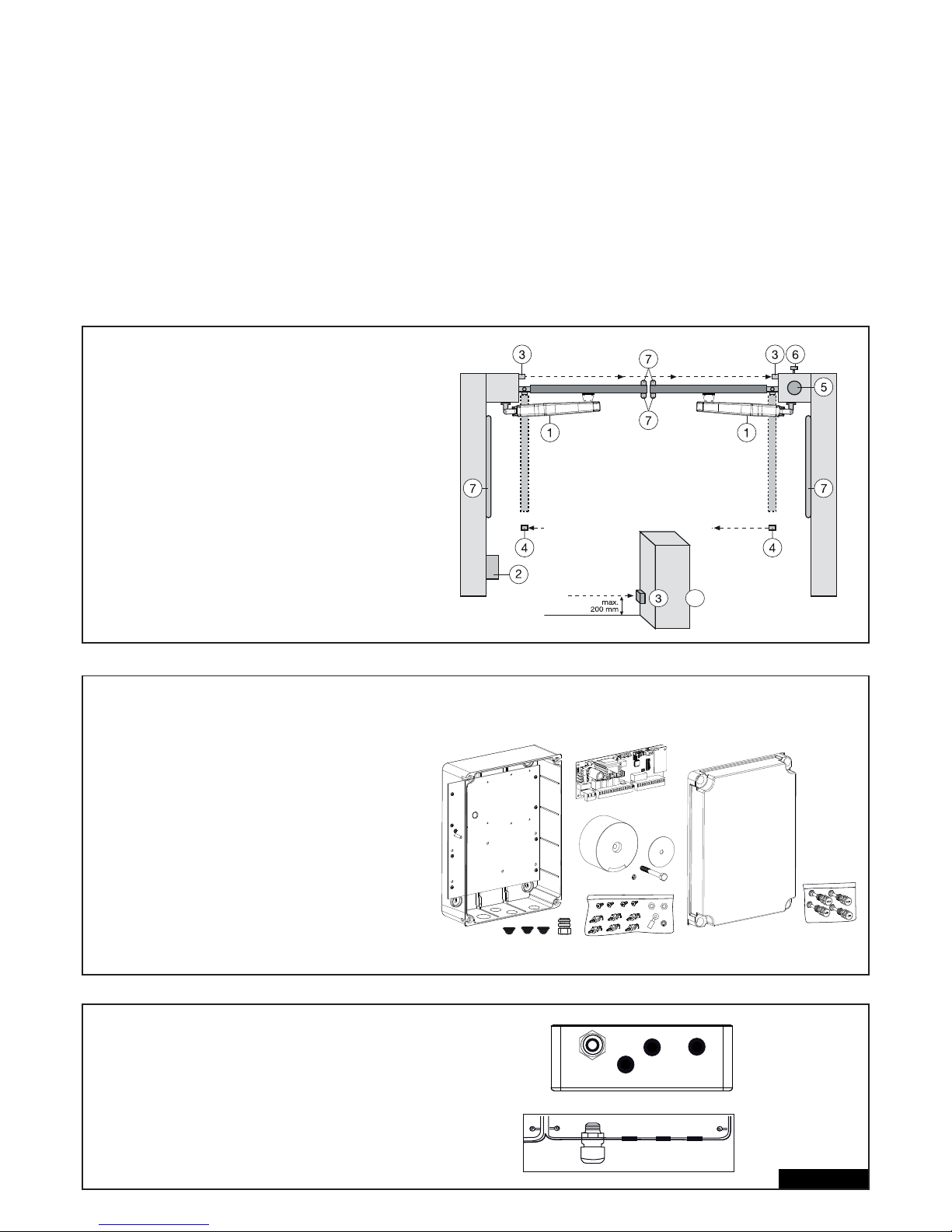
DATOS TÉCNICOS DEL CONTROL DEL MOTOR
Tensión: 230V~+/- 10% 50-60 Hz
Transformador: 230/24V CA, 150VA
Salida motor: 24V CC
Consumo máx.: máx. 400W (en funcionamiento)
Consumo en espera: máx. 4W (sin accesorios)
Alimentación accesorios: 24V CC / 600mA máx.
Temperatura de trabajo: -25ºC ÷ +55ºC
Funcionamiento: estándar, automático
Dimensiones: 250x75mm (sin caja)
Abmessungen Box: ca. 300x220x120mm
Grado de protección: IP45
Fusible: 2 x 2A (rápido)
Emisor manual: máx. 170 x Rolling Code
Frecuencias posibles: 433MHz, 868MHz
ESTRUCTURA TÍPICA DE UNA INSTALACIÓN :
1. Motor
2. Mando
3. Fotocelula (activa en cerrado), altura máx. 200 mm
Primera fotocelula .
4. fotocelula (activa en abierta/cerrado), altura máx. 200 mm
Segunda fotocelula (opcional).
5. Luz intermitente (opcional)
Importante observación óptica sobre el movimiento de la
puerta.
6. Interruptor de llave o cerrojo de codifi cación (opcional)
Se coloca en el lado exterior. Mediante la llave o la introduc ción de un número se abre la puerta.
7. Regleta de contacto (opcional)
Asegura la puerta en caso de tocarse. Las regletas de cont acto se pueden colocar en la puerta o en las columnas. Si es
necesario, las regletas de contacto se deben colocar hasta
una altura de 2,5 m.
2/16 es
MONTAJE DE LA CAJA DE MANDO
En la caja de mando se encuentran varias piezas:
- Montaje externo caja 1 unidad
- Tapa para la caja 1 unidad
- Mando 1 unidad
- Transformador 1 unidad
- Placa de base (premontado) 1 unidad
- Paso de cable grande 1 unidad
- Paso de cable pequeño 3 unidades
- clip de fi jación 6 unidades
- Tornillos 3,5 x 9,5 mm 4 unidades
- arandela grande 1 unidad
- tornillo largo 1 unidad
- argolla para fi jar cables 1 unidad
- tuerca M8 1 unidad
- arandela M8 1 unidad
- tornillos roscados grandes 5unidades
PREPARATIVOS DE LA CAJA DE MANDO
Abrir los 4 agujeros en el fondo de la carcasa
mediante desatornillador o una herramienta similar.
Fijar el paso grande de cable a la izquierda, los
restantes tal como muestra.
La humedad y el agua destruyen el mando. Todas
las aberturas y pasos de cables tienen que estar
cerradas necesariamente de modo impermeable al
agua. La caja de mando con el mando del motor se
debe montar con los pasos de cables hacia abajo.
4
+
Page 93
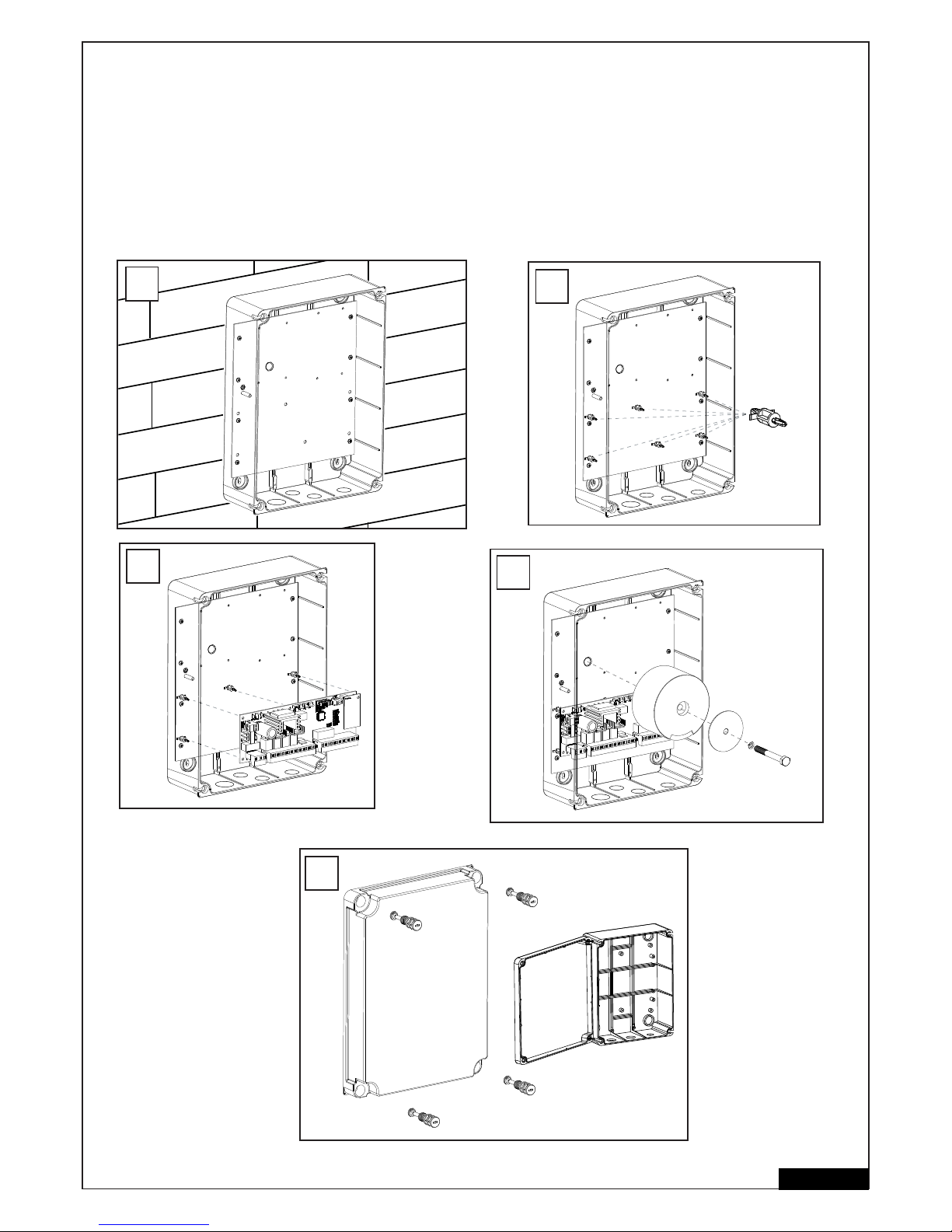
MODO DE PROCEDER RECOMENDADO
Atornillar la parte inferior de la carcasa en la pared. Antes, medir las distancias necesarias y establecer los taladros adecuados (material de
fi jación no incluido). La placa de base ya es premontado (A).
Pulse los clips de fi jación en los agujeros previstos (B).
Pulse el control sobre los clips de fi jación (C).
Atornillar el transformador con el tornillo grande y la arandela grande en la placa de montaje. (D)
Pase los 4 tornillos grandes de cierre de la caja por la tapadera de la misma. Atornille 2 de los tornillos de cierre (a la izquierda o derecha)
aprox. 2 cm en la caja. A continuación, se puede abatir la tapadera hacia un lado (E). Cierre la caja a modo de prueba apretando por completo
los tornillos. Si la tapadera no cierra correctamente, es que la caja se apoya de modo no uniforme en la pared alabeándose. Esto se debe
corregir. Es muy importante que la caja cierre luego de modo impermeable al agua.
3/16 es
6x
B
C
D
A
E
Page 94
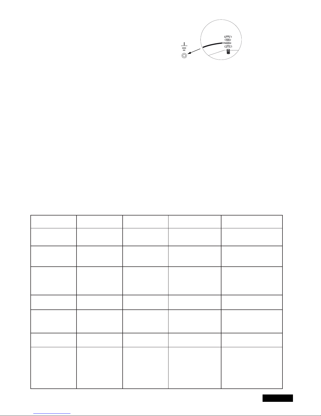
CABLEADO DEL MANDO / VISIÓN DE CONJUNTO:
a. Comience con el cable de alimentación de 230 voltios en el lado
izquierdo de la caja aún sin tensión.
b. Colocar la argolla de cable en el conductor de puesta a tierra.
Una el conductor de toma a tierra del cable de alimentación con
la placa de base. Conecte todos los demás cables al mando.
CABLES Y CABLEADO
Se recomienda usar cables blindados desde el motor al control.
La infl uencia magnética e inductiva en el cable puede provocar zumbidos y perturbar el funcionamiento de la puerta.
Evite de forma general:
- colocar el control demasiado alejado de la puerta.
- Tender juntas líneas de 230voltios y de baja tensión. No permitido conforme a las normas de instalación eléctrica.
No tender los cables para fotocelulas, interruptores, lámpara intermitente y cierre eléctrico junto con el cable del motor.
- No tender el cable de telecomunicación o los cables para la iluminación del garaje tampoco con el cable del motor.
- Los cables de cobre rígidos son difíciles de cablear, especialmente para diámetros mayores de cable. Utilice cables fl exibles.
- Utilice cables que sean adecuados para el exterior y el tendido en el suelo o tubos vacíos adecuados o consulte a su técnico electricista.
Recomendamos los siguientes accesorios:
- Kit LA400-JB40E Kit para la prolongación de cables para una instalación. Formado por cable de 12 m, 6 polos con los mismos colores que
accionamiento, caja de distribución IP65, racores atornillados para cables y material de fi jación.
- 041ASWG-0482-50 50 m Anillo, cable de conexión de 50 m, 6 polos para el exterior. Tendido posible su tubo vacío. Con los mismos colores que
en el accionamiento.
Tamaños de cables:
Las dimensiones en la tabla son tamaños mínimos. Pueden utilizarse diámetros mayores en todo momento
- Tensión de alimentación de 230 voltios para el control: mín. 0,75mm² 3 polos
- Alimentación de 230 V para transformador instalada de forma separada (p. ej., en el garaje) y tensión baja a la puerta. Véase la tabla.
- Cableado del motor: 2 cables mín. 1,0mm², 4 cables mín. 0,75mm² (o cables blindados)
- Cierre eléctrico: Véase la tabla
- Interruptor, fotocelulas, lámpara intermitente: Véase la tabla, etc., mín.0,5mm²
4/16 es
Modelo de accionamiento
LYN, SCS, ART
Cableado del motor
SUB (accionamiento
subterráneo)
Cableado del motor
Transformador instalado
de forma separada (en
el garaje) y alimentación de baja tensión del
control
Cierre eléctrico (12 V)
Cableado
Antena externa (retire la
antena original del
control)
Interruptor, lámpara
intermitente, etc.
Fotocelula
Distancia
0m - 6m
2 x 1,0mm²
4 x 0,75mm²
2 x 1,0mm²
3 x 0,75mm²
0,75mm²
0,75mm²
Cable coaxial
50 Ohm
0,5mm²
0,5mm²
Distancia
6m - 10m
2 x 1,0mm²
4 x 0,75mm²
2 x 1,0mm²
3 x 0,75mm²
0,75mm²
0,75mm²
Cable coaxial
50 Ohm
0,5mm²
0,5mm²
Distancia
6m - 10m
2 x 1,0mm²
4 x 0,75mm²
2 x 1,0mm²
3 x 0,75mm²
0,75mm²
0,75mm²
Cable coaxial
50 Ohm
0,5mm²
0,5mm²
Distancia
12m – xx
Max. 15m Utilizar cables
blindados para los 4 cables más
pequeños del motor
Utilizar cables blindados para
los 3 cables más pequeños del
motor
Max. 30m; Min. 1,5mm²
Peso de la puerta máximo 50%
de la potencia máxima del motor
Max. 30m; Min. 1,5mm²
Cable coaxial
50 Ohm
(max. 25m)
Min. 0,75mm²
Max. 30m
Min. 0,75mm²
Page 95
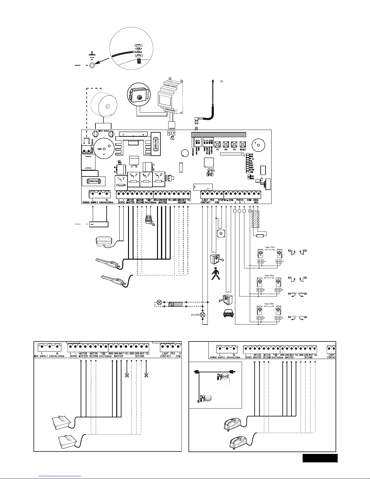
5/16 es
ESQUEMA DE CONEXIONES
LYN/SCS
230VAC
PE
PE
Model
203285
Ω
8.2
+
+
+
+
+
+
+
Relay
+++
+
-
RED
RED
BLUE
BLUE
Model
CM475
BROWN
GREEN
WHITE
BROWN
GREEN
WHITE
YELLOW
YELLOW
RADIO MODULE
Model
207399
230 VAC
50
RED
RED
BLUE
BLUE
BROWN
GREEN
WHITE
BROWN
GREEN
WHITE
not required
not required
RED
RED
BLUE
BLUE
BROWN
GREEN
WHITE
BROWN
GREEN
WHITE
YELLOW
YELLOW
ART
SUB
Closed position
Open position
Batería adicional
externa
Page 96
FUNCIONES DE LOS PULSADORES P1, P2, P3 & RESET
P1+P2+P3
P1
P1 + P2
P2 + P3
P1 + P3
P2
P3
DIP „RADIO“ + P1
DIP „RADIO“ + P2
RESET
Funcionamiento simple. Las alas pueden moverse de forma individual. Activar la función: Pulsar simultáneamente P1+P2+P3.
El LED LEARN parpadea mientras está activada la función. La tecla P1 mueve el motor 1. La tecla P2 mueve el motor 2.
Desactivar la función: Esperar 20 seg. o desembornar el control. Si las alas se cierran primero, intercambie los cables rojo y azul.
Programa automáticamente las posiciones fi nales del recorrido.
Programa automáticamente las posiciones fi nales del recorrido (así como posiciones adicionales, p. ej., Soft-Start y Soft-Stop).
Retardo del cierre eléctrico
Ajuste del retardo de ala
Cerrar automáticamente. Para la confi rmación se necesita la tecla P2
Restauración de software con los ajustes de fábrica. Pulsar la tecla durante 10 seg. La restauración no afecta a la memoria de
radio (véase radio)
Programación del emisor manual canal 1 Señal para ambos accionamientos (alas)
Programación del emisor manual canal 2 Señal para un accionamiento (motor 1).
Programar interfaz Internet o supervisión de puerta: Nota: la tecla RESET no provoca una restauración al ajuste de fábrica
para este control. Sirve únicamente para programar la interfaz de Internet o la supervisión de puerta. Véase la descripción
de la tecla P3 para una restauración al ajuste de fábrica.
Tecla Función
6/16 es
DESCRIPCIÓN DE BORNES
DESCRIPCIÓN FUNCIONES
L conexión L 230 voltios línea de alimentación
N conexión N 230 voltios línea de alimentación
30VDC Conexión de una batería externa
Motor MASTER Motor 1 (Master, se abre primero)
Motor SECOND Motor 2 (Second, se abre segundo)
Para la comprobación de la polaridad correcta, véase la sección
„Ajuste básico“ y „Función de los pulsadores P1,P2,P3 & RESET“
24V /150mA luz intermitente (accesorio)
MASTER Motor1
BRN cable marrón
GRN cable verde
WHT cable blanco
YEL cable amarillo
SECOND Motor2
BRN cable marrón
GRN cable verde
WHT cable blanco
YEL cable amarillo
Light Contact Supervisión de puerta / iluminación del jardín
PED Conexión para parada de emergencia o
COM Negativo
STOP Interruptor de emergengencia / de stop
“Símbolo de llave” interruptor de llave
COM Negativo
PHOTO 3 fotocelula 3 (abrir)
PHOTO 2 fotocelula 2 (abrir & cerrar)
PHOTO 1 fotocelula 1 (cerrar)
COM Negativo
EDGE Regleta de contactos con 8,2kOhm
8,2KOhm
„Símbolo“ cerradura E Entrada cerradura eléctrica “Entrada
de mando”
INPUT 24VAC 24 voltios tensión de entrada del transformador.
Se puede conectar con la polaridad que se desee.
Transformer 230VAC 230 voltios cable alimentación al transformador.
Se puede conectar con la polaridad que
se desee.
250V/2A Fusible 250V/2A (2x rápido)
DESCRIPCIÓN DE LOS LEDS (DIODOS LUMINOSOS)
Descripción Color Función
STOP Verde Parada de emergencia / Stop
ON: Parada de emergencia /Stop activa
OFF: OK (Puente de cable cuando no hay
conectado ningún interruptor)
EDGE Verde Regleta de contactos 8,2KOhm
ON: están activados
OFF: OK (puentear con 8,2Kohm de
resistencia cuando no hay conectada
una regleta de contacto)
“Símbolo de llave” Rojo interruptor de llave
CONECTADO: Interruptor accionado
DESCONECTADO: Interruptor no
accionado
PED Rojo Interruptor de llave 1 ala
ON: Interruptor accionado
OFF: Interruptor no accionado
PHO1 Rojo fotocelula 1 (cerrar)
CONECTADO: OK (activa)
DESCONECTADO: no fotocelula
PHO2 Rojo fotocelula 2 (abrir & cerrar)
CONECTADO: OK (activa)
DESCONECTADA: no fotocelula
PHO3 Rojo fotocelula 3 (abrir)
CONECTADO: OK (activa)
DESCONECTADO: no fotocelula
LEARN Amarillo estado del programa de aprendizaje
CONECTADO: Programa de aprendizaje
activo
DESCONECTADO: Ningún programa
de aprendizaje
DGN Rojo programa de diagnóstico (ver “cuestiones
que se plantean con frecuencia“)
CH1 Rojo Programación del emisor manual para
funcionamiento de 2 alas
ON: El nuevo emisor de mano puede
programarse
OFF: Función desactivada
CH2 Rojo Programación del emisor manual para
funcionamiento de 1 alas (véase CH1)
Page 97

7/16 es
ACCESORIO (ve tambien Esquema de conexiones)
RADIOCONTROLES (OPCIONAL) MODELO: TX2EV, TX4EV, TX4UNI (Telemandos), 747EV (Sistema de acceso
sin llave) , 128EV (Pulsador mural radio con 2 funciones)
LÁMPARA INTERMITENTE (OPCIONAL) MODELO: FLA24-2, FLA1-LED
Se puede conectar una lámpara intermitente al mando (Bornes: 24 VDC / 150 mA). Advierte a personas frente a la puerta en movimiento.
La lámpara intermitente se debe colocar lo más elevada y visible posible. El mando emite una señal constante que es transformada por la lámpara
en un encendido intermitente.
INTERRUPTOR DE LLAVE (OPCIONAL) MODELO: 100010, 100027, 100034, 100041
El mando / el accionamiento se puede activar mediante el interruptor de llave. (Bornes: símbolo de llave y COM)
Véase también bajo descripción Interruptores DIP „OPEN/PED“.
INTERRUPTOR DE PARADA DE EMERGENCIA / DE STOP (OPCIONAL) MODELO: 600084
Puede conectarse en esta salida un interruptor de parada de emergencia (Bornes: STOP / 8.2 kOhm), que detiene la puerta en todos los
sentidos. Véase también bajo descripción Interruptores DIP „STOP/8,2kOhm“.
REGLETA DE CONTACTO (OPCIONAL) MODELO: 600046, 600053, 600077, 600060
(El interruptor DIP „LOOP/EDGE“ debe estar apagado )
En el mando se puede conectar una regleta de contacto (Bornes: STOP / 8.2 kOhm) que funciona según el principio de 8,2 Kohmios, es decir,
al fi nal de la regleta de contacto se encuentra fi jada una resistencia de control de 8,2 Kohmios. Esta garantiza la supervisión continua del
circuito de corriente. El mando se suministra con una resistencia incorporada de 8,2 Kohmios. Varias regletas de contacto se conectan en serie.
Véase también bajo descripción Interruptores DIP „STOP/8,2kOhm“.
BARRERAS DE LUZ (OPCIONAL) MODELO 771E, 772E:
Se recomienda el uso de una barrera de luz. Utilice el modelo 771E o 772E, que también es parte del Safety Accessory Kit APLUS-EV.
SAFETY ACCESSORY KIT (OPCIONAL): APLUS-EV
El control ya está equipado con una antena estándar. Para alcances mayores puede conectarse una antena externa de los accesorios APLUS-EV
(contiene barrera de luz 771E, lámpara de destellos FLA1-LED y antena externa SWG-ANT-EV) como se muestra en la vista de conjunto de
conexiones.
myQ (OPCIONAL):
(solo con interfaz Internet 828EV):
Permite manejar la puerta a través de Internet o smartphone.
SUPERVISIÓN DE PUERTA (OPCIONAL):
(solo con supervisión de puerta 829EV):
Permite un control óptico y acústico de la posición de la puerta. La puerta también puede cerrarse con este aparato.
BATERÍA (OPCIONAL)
Las conexiones sirven para cargar una batería externa.
En caso de un fallo de corriente, la batería suministra energía al accionamiento. Una batería completamente cargada puede suministrar
energía durante más de 24h. Las baterías están sujetas al proceso de envejecimiento y pierden capacidad. En función del uso, sustituya la
batería cada 2-3 años.
CERRADURA ELÉCTRICA (OPCIONAL)
El mando ofrece la posibilidad de utilizar una cerradura eléctrica de 12 V. (las instrucciones se adjuntan a la cerradura eléctrica).
Para esto, hay que conectar en el mando principal un mando auxiliar para la cerradura eléctrica. Si el cierre eléctrico no se abre debido a una
presión excesiva de la puerta, puede programarse una función especial: Pulse P2 y P3 simultáneamente durante unos 5 segundos y cuente los
chasquidos que se oyen.
1 chasquido = aprox. 4 segundos corrientes al cierre eléctrico (ajuste de fábrica)
2 chasquidos = la puerta se cierra durante un segundo y se abre a continuación. Además, una vez alcanzada la posición de puerta cerrada, el
accionamiento ejerce presión brevemente para contribuir al enclavamiento de la cerradura eléctrica. Nota: en este sentido, la puerta debe estar
equipada con topes de suelo.
SUPERVISIÓN DE PUERTA O ILUMINACIÓN (OPCIONAL)
Las conexiones tienen dos funciones en función de si está enchufado o no el puente de enchufe Light / Spy. Véase también „Puentes de
enchufe“ en estas instrucciones. La salida no tiene un suministro de corriente propio y sólo se puede cargar hasta 24 V.
Supervisión de puerta / estado de la puerta (Spy)
Un LED, una lámpara (24V / 3W máx.) o un relé pueden conectarse a los bornes para mostrar el estado de la puerta.
LED apagado = puerta cerrada
LED intermitente lento = la puerta se abre
LED encendido = puerta abierta
LED intermitente rápido = la puerta se cierra
Iluminación de patio / iluminación durante 120 segundos
Una lámpara (24V / 3W máx.) o un relé pueden conectarse en los bornes.
Si el control recibe una señal de abertura o cierre, la lámpara se ilumina durante 120 segundos y luego se apaga automáticamente.
ATENCIÓN: La salida solo puede cargarse hasta 24V como máximo o deberá intercalarse un relé.
Page 98
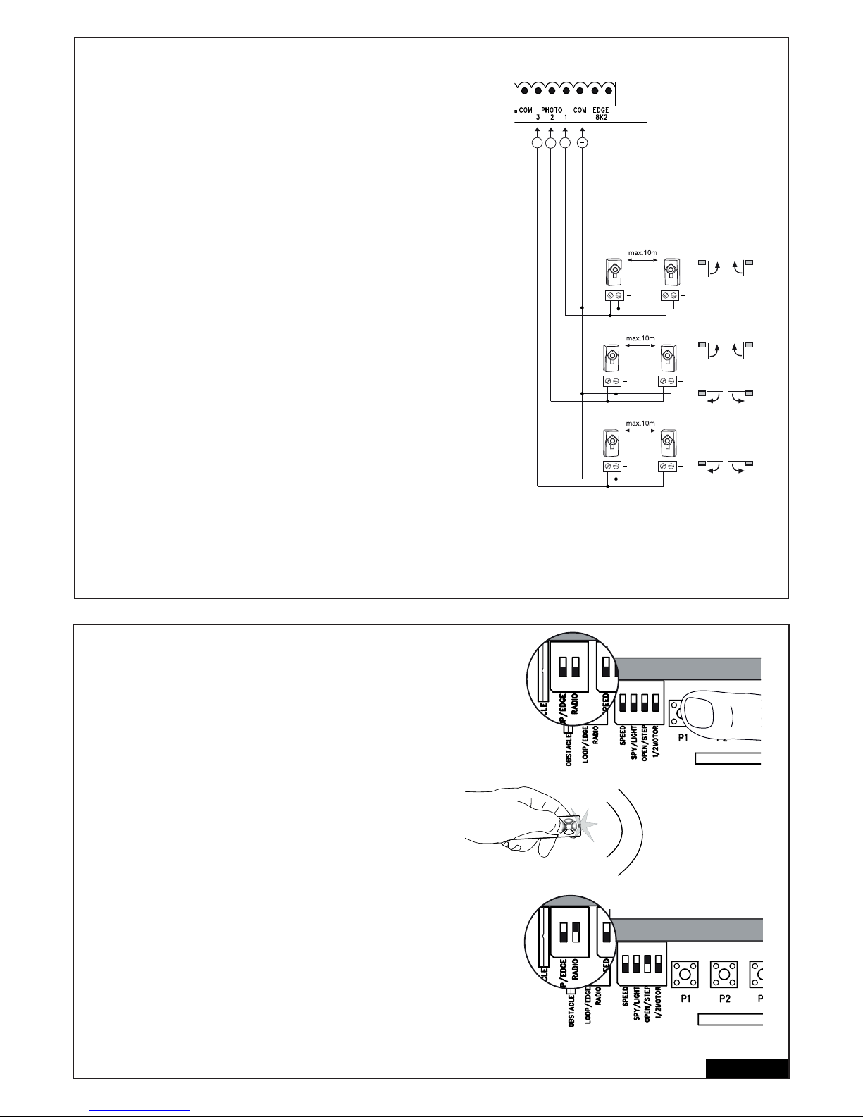
8/16 es
FOTOCELULAS (OPCIONAL) : 771E, 772E
Las fotocelulas sirven para el aseguramiento de la puerta y se tienen que emplear.
El lugar de montaje depende del tipo de construcción de la puerta. Según la norma
EN12453, se tiene que instalar fuera un par de fotocelulas a una altura de 200 mm
activas en „cerrar“. Las fotocelulas constan de un emisor y un receptor y tienen que
encontrarse una pieza enfrente de la otra. La fotocelula se debe fi jar a la pared
mediante tornillos y tacos pequeños. Si se quiere que sea posible la función „cierre
automático“, se tiene que instalar la fotocelula Chamberlain – Failsafe. El sistema
Chamberlain –Failsafe (sistema de 2 cables) posee en ambos lados un pequeño LED
(luz) que se puede ver desde fuera, para mostrar el estado de la fotocelula.
Programación de la fotocelula:
- Conectar fotocelula
- Realizar la programación de recorrido del ala de la puerta.
Eliminación de una fotocelula del control:
Una fotocelula conectada no puede quitarse sin que el control bloquee la función
en la correspondiente conexión. Para eliminar la fotocelula del programa del control.
- Quitar la fotocelula
- Desactivar brevemente la corriente
- Realizar la programación de recorrido del ala de la puerta.
Diagnóstico en la fotocelula Chamberlain-Failsafe
LED constante = OK
LED parpadea = la fotocelula bloquea el mando
LED apagado = no hay corriente, conexión errónea o polarización cambiada
Diagnóstico en el mando
LED apagado = OK, ninguna fotocelula conectada
LED encendido parpadea = el mando bloquea
Conexión 1 & COM
Activa cuando la puerta se cierra (invierte la puerta)
Conexión 2 & COM
Activa cuando la puerta se cierra y se abre
Conexión 3 & COM
Activa cuando la puerta se abre
(la puerta permanece parada hasta que se quita el obstáculo del
haz de infrarrojos, posteriormente sigue moviéndose)
MÓDULO DE RADIO
PROGRAMAR / BORRAR DE TELEMANDOS
El receptor tiene dos canales CH1 y CH2. El uso de los dos canales
permite de abrir un solo batiente o de los dos. Por ejemplo si CH2 =
P2 recibe la señal del telemando se abre solamente 1 batiente.
Cuando se usa un otro boton del telemando con CH1 se abran
los dos batientes.
PROGRAMACIÓN
1: Encender el interrupor DIP „RADIO“.
2: Pulsar brevemente el botón P1 (para CH1) o P2 (para CH2) y el LED
correspondiente se enciende.
3: Mantenga pulsado ahora el botón deseado en su mando a distancia
hasta que el LED se apague después de un breve parpadeo. ¡Listo!
Repita estos pasos para todos los mandos a distancia (pueden progra marse 85 mandos para canal máximo).
Importante: después de la programación de su(s) mando(s) a distancia, apagar el interruptor DIP „RADIO“. Nota: asegúrese de no programar el mismo
botón de su mando a distancia en CH1 y CH2; de lo contrario, el sistema no
funciona correctamente.
BORRAR
- Encender el interrupor DIP „RADIO“.
- Mantener pulsado el botón P1 hasta que el LED eliminado se apague
después de unos 10 segundos. ¡Listo!
Para la confi rmación, los dos LED CH1 y CH2 parpadean 8 veces.
- Apagar el interruptor DIP „RADIO“.
RADIO MODUL
E
ON ON
RADIO MODUL
E
ON ON
RA
ON ON
RA
ON ON
+
+
+
+
+
+
+
+++
Page 99
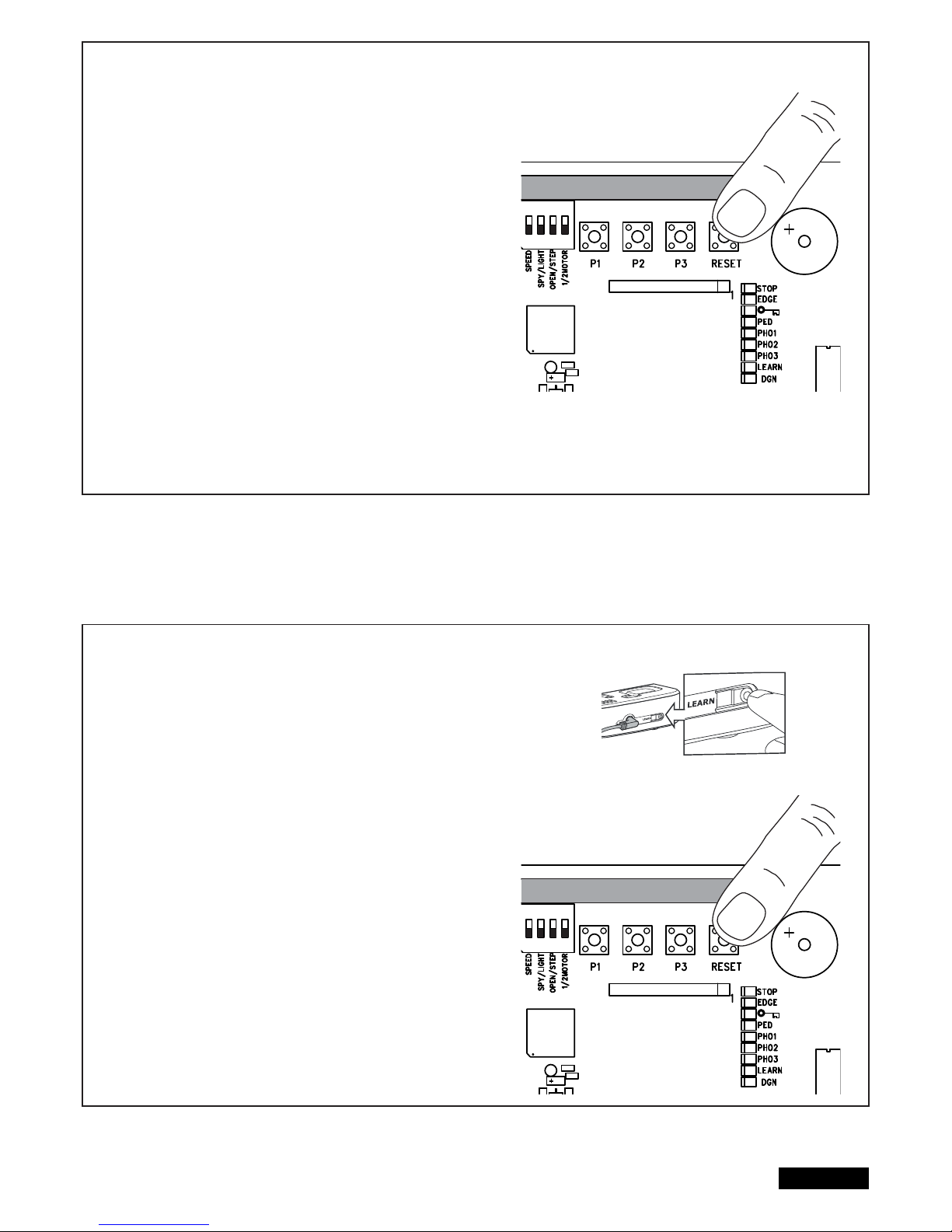
9/16 es
PROGRAMACIÓN DE LA INTERFAZ INTERNET myQ
Con la tecla RESET en el control
1. Conectar la interfaz Internet Liftmaster y su enrutador con el cable de red.
2. Alimentar con corriente la interfaz Internet Liftmaster.
3. Crear una cuenta online con la aplicación para smartphone más reciente
Liftmaster myQ o en www.liftmaster.eu.
4. Registrar la interfaz Internet Liftmaster.
5. Hacer clic en „Añadir nuevo aparato“ y seguir los pasos de la aplicación o del
sitio web.
6. Nota: Si pulsa la tecla REST oirá un pitido y los LED CH1 y CH2 se encen derán y, una vez realizado el ajuste, parpadearán tres veces y se apagarán.
7. La aplicación le muestra si la programación se realizó correctamente y le
pedirá que asigne un nombre para la puerta.
PROGRAMACIÓN DE LA SUPERVISIÓN DE PUERTA
Con la tecla RESET en el control
1. Alimentar de corriente la supervisión de puerta y colocarla en la casa de
modo que esté bien visible. Si el lugar de instalación está demasiado alejado
de la puerta, la conexión puede estar perturbada o interrumpida. Coloque el
aparato en un lugar más apropiado.
2. Pulsar brevemente y soltar la tecla „LEARN“ en la parte trasera de la super visión de puerta. Los LED rojo y verde parpadean de forma alternante. En
un intervalo de 60 segundos, pulsar y soltar la tecla RESET en el control.
Para confi rmar la programación se encienden los LED rojo y verde.
BORRAR SUPERVISIÓN DE PUERTA
Pulsar durante 10 segundos como mínimo la tecla „LEARN“ en la parte trasera
de la supervisión de puerta.
Un breve pitido confi rma el correcto borrado.
ADIO MODULE
ADIO MODULE
Page 100
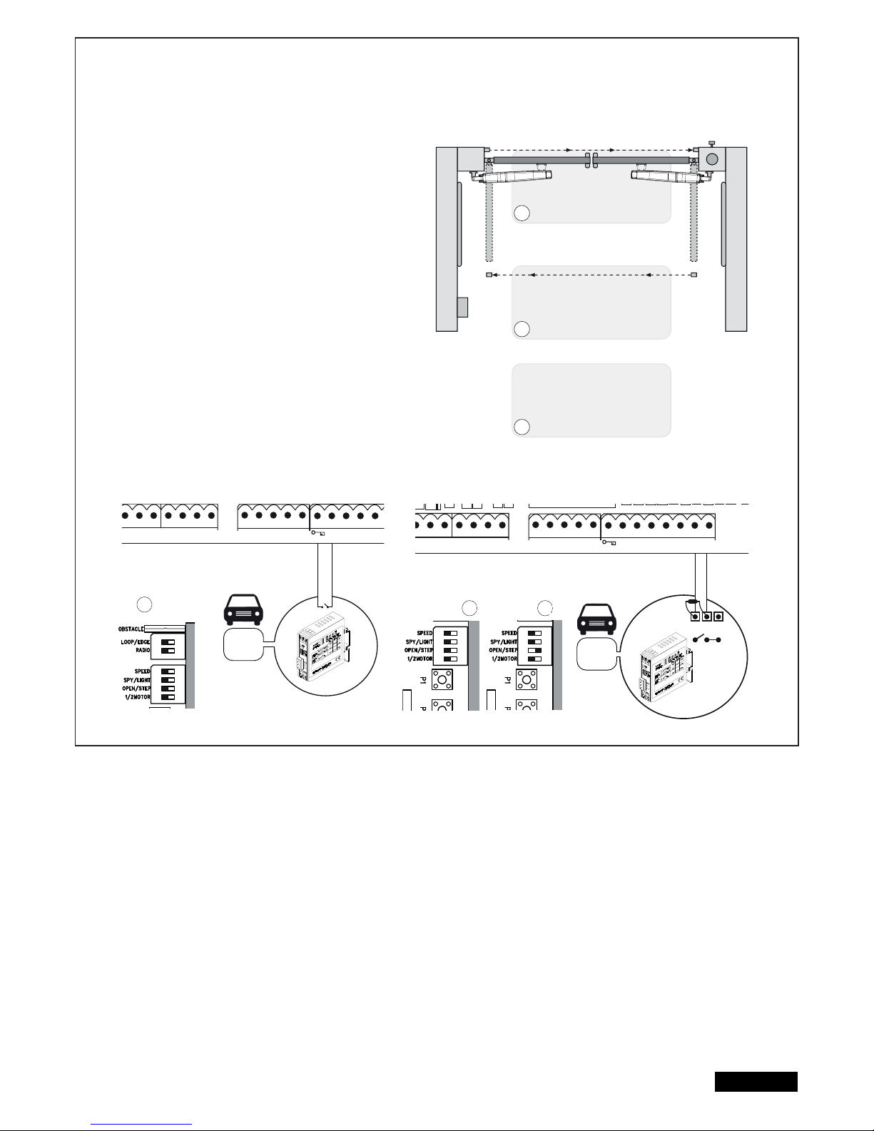
DETECTORES DE BUCLE
(El interruptor DIP LOOP/EDGE debe estar encendido)
Los detectores de bucle reaccionan al metal y se utilizan
principalmente para la detección de coches y camiones,
pero no de motos y peatones.
Bucle de salida A
El bucle de salida se encuentra detrás de la puerta y abre
la puerta cuando está cerrada, la mantiene abierta o la
abre nuevamente. Los interruptores de enchufe OPEN /STEP
y LOOP/EDGE deben estar encendidos.
Las fotocelulas deben estar conectadas y la función
„Cerrar automáticamente“ debe estar activada.
Detector de bucle de seguridad y
detector de bucle en la zona de giro de la puerta B,C
Los detectores de bucle sirven para la detección de vehículos
(coches, camiones, pero no se permiten como medida de
protección exclusiva, ya que no detectan personas.
La unidad de evaluación de los detectores de bucle se conecta
como emisor de señales NO en los terminales de la regleta de
contactos de 8,2kOhm. Si desea utilizar también regletas de contactos:
Compruebe antes de la instalación cuál es el modo de
funcionamiento adecuado para éstas.
Detector de bucle de seguridad
=>El interruptor DIP OPEN /STEP debe estar encendido.
Detector de bucle en la zona de giro de la puerta
=> El interruptor DIP OPEN/STEP debe estar apagado
En nuestro departamento de servicio pueden consultarse otras
opciones para detectores de bucle.
10/16 es
RN WHT YEL
ASTER
BRN GRN WHT YEL
SECOND
COM
PHOTO
3 2 1
C
LIGHT
CONTACT
PED
COM
STOP
NO
Model
203292
Model
203292
RN WHT YEL
ASTER
BRN GRN WHT YEL
SECOND
COM
PHOTO
3 2 1
COM EDGE
8.2KΩ
LIGHT
CONTACT
PED
COM
STOP
NO
COM
NC
A
B
C
A
B C
RADIO
ON ON
RADIO
MOD
ON
RADIO
MOD
ON
 Loading...