

Page 1
STAR
TM
450-315 WIRELESS
ACCESS CONTROL
RECEIVER
This device complies with FCC Rules Part 15 and IC Canada Rules
and Regulations. Operation is subject to the following two
conditions: (1) This device may not cause harmful interference
and (2) this device must accept any interference received,
including interference that may cause undesired operation.
Removable memory modules and RF module are included in this
product. Jumper J2 must remain in the default position unless
otherwise noted. THERE ARE NO OTHER SERVICEABLE PARTS.
DESCRIPTION PAGE
Mounting Instructions for STAR450 . . . . . . . . . . . . . . . . . . . . . .1
Programming For STAR450 . . . . . . . . . . . . . . . . . . . . . . . . . . .2-3
Troubleshooting Guide . . . . . . . . . . . . . . . . . . . . . . . . . . . . . . . . .4
Electrical Connections for STAR450 . . . . . . . . . . . . . . . . . . . . . .4
STAR450 Features . . . . . . . . . . . . . . . . . . . . . . . . . . . . . . . . . . . .4
SPECIFICATIONS
SUPPLY VOLTAGE: 12-24 VOLTS AC OR DC
OPERATING CURRENT: 250 mA MAXIMUM
OPERATING TEMP RANGE: -40 TO +149F
(-40 TO +65C)
FREQUENCY: 315 MHz
RELAY CONTACT RATING: 1 AMP @ 24 VOLTS AC OR DC
Location: Select a convenient location near your device to be
controlled by the STAR450. For best performance, the STAR450
should be mounted in “Line-Of-Sight” with your intended
transmitting location. Avoid mounting the STAR450 in or on
metallic enclosures. If this is unavoidable, we recommend
installing the antenna extension kit (86LM) for best results. See
Remote Antenna Mounting for proper installation.
Receiver Mounting: Mount back plate to desired surface using #6
hardware (not provided). Hardware used will depend on mounting
application (refer to Figure 1 for receiver mounting hole
locations). Wire electrical connections to unit. Snap unit to back
plate.
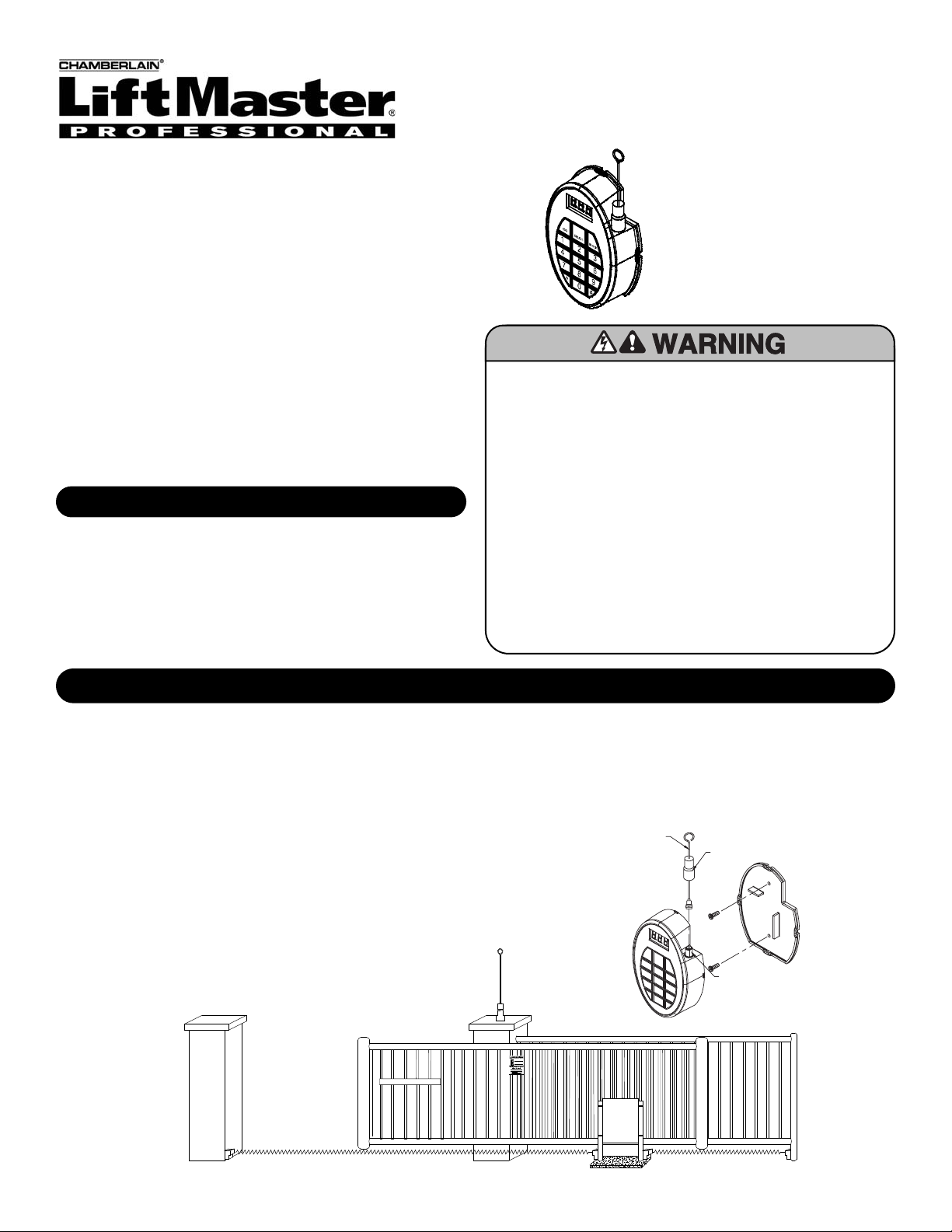
Direct Antenna Mounting: Install the provided antenna onto the
STAR450 antenna connector by screwing the connector
clockwise. Slide the seal boot down to meet the O-ring, covering
the antenna hardware.
Antenna
Antenna
Connector
Seal Boot
Figure 1
Figure 2
Remote Antenna Mounting: Use the optional 86LM antenna
extension kit to mount the remote antenna as high and far from
metal as possible for best radio range (Figure 2). Contact
LiftMaster customer service at: 1-800-528-2806 to order the
model 86LM.
To prevent possible SERIOUS INJURY or DEATH from
electrocution:
• Be sure power is not connected BEFORE installing the
receiver.
To prevent possible SERIOUS INJURY or DEATH from a
moving gate or garage door:
• ALWAYS keep remote controls out of reach of children.
NEVER permit children to operate, or play with remote
controls.
• Activate gate or door ONLY when it can be seen clearly, is
properly adjusted, and there are no obstructions to door
travel.
• ALWAYS keep gate or garage door in sight until completely
closed. NEVER permit anyone to cross path of moving gate
or door.
TABLE OF CONTENTS
MOUNTING INSTRUCTIONS FOR STAR450
Page 2
2
PROGRAMMING THE STAR450
PRESS
TO EXIT
PRESS
#
PRESS
Add
Add
AUTO
001
PRESS
ENTER LOCATION (1-450)
PRESS
PRESS
TO EXIT
#
AUTO
Add
Add
001 002
2
3
4
023
234
PRESS
ENTER LOCATION (1-450)
PRESS
TO
CONFIRM
END
Delete Delete
Del
Del
2
3
4
002 023
234
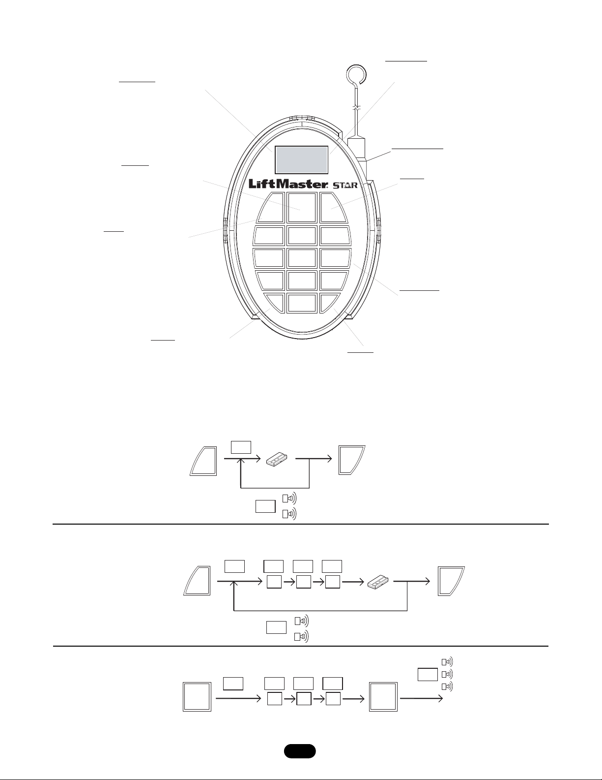
Rapid LearnTM: Add remote control to next available location.
Adding Remote Control: Add remote control to a specific location.
Deleting a Remote Control: To delete a user.
DELETE KEY
USED TO DELETE A REMOTE CONTROL
FROM THE SELECTED MEMORY LOCATION
DIGITAL DISPLAY
DISPLAYS REMOTE CONTROL LOCATION
NUMBERS WHEN PROGRAMMING OR
ACCESS IS GRANTED. ALSO DISPLAYS
USER PROMPTS AND MESSAGES.
POWER INDICATOR
SCROLLING DASHES ON
DIGITAL DISPLAY WHEN
AC OR DC POWER IS
APPLIED TO THE UNIT.
BLOCK KEY
USED TO BLOCK THE
RECEIVER FROM
GRANTING ACCESS TO
THE SELECTED REMOTE
CONTROL. REMOTE CONTROL
REMAINS IN MEMORY, AND
MAY BE UNBLOCKED IN
THE FUTURE.
Block
3
*
#
6
9
2
5
8
0
1
4
7
DeleteAdd
NUMERIC KEYPAD
USED FOR PROGRAMMING
AND QUERYING REMOTE CONTROL
LOCATIONS. ALSO USED TO ENTER
ADVANCED FUNCTIONS.
ANTENNA CONNECTION
FOR CONNECTION TO THE
DIRECT ANTENNA OR THE
ANTENNA EXTENSION KIT.
ADD KEY
USED TO ENTER REMOTE CONTROLS
AND ENTER RAPID LEARN MODE.
POUND KEY
USED AS AN ESC OR EXIT KEY FOR ALL
FUNCTIONS OR MODES.
STAR KEY
USED TO ENTER ADVANCED FUNCTIONS:
✱, 1- LAST REMOTE CONTROL RECEIVED
✱, 2- NO. OF UNUSED MEMORY LOCATIONS
✱, 3- NO. OF OCCUPIED MEMORY LOCATIONS
✱, 4- NO. OF BLOCKED REMOTE CONTROL LOCATIONS
✱, 5- FIRST BLOCKED REMOTE CONTROL LOCATION
✱, 7- SOFTWARE VER. #
✱, 0- AUDIBLE DIAGNOSTICS OFF/ON
TM
STAR450 FEATURES
Page 3
3
PROGRAMMING THE STAR450 (CONT’D)
ADVANCED FUNCTIONS
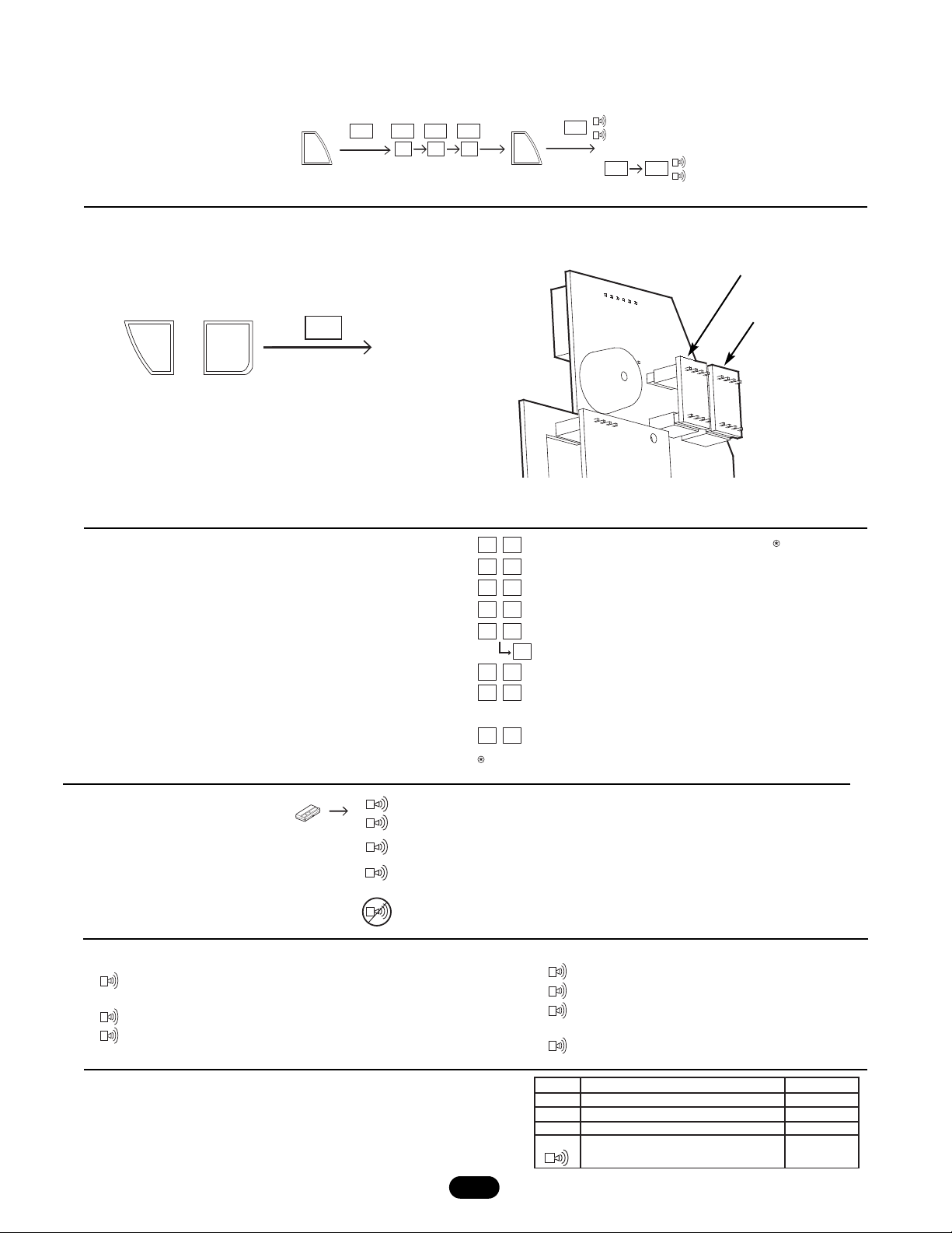
For advanced functions, press and hold the ✱ key and a
number key at the same time to select the corresponding
advanced function. (See table at right for available functions.)
Press the # key to exit the function.
REMOTE CONTROL LOCATION QUERY
Enter a remote control location number (001-450) to view location
status (see table to the right for possible status displays).
ENTER LOCATION (1-450)
(UNBLOCK)
END
PRESS
TO
CONFIRM
PRESS
Block
Block
Un- bLc
bLc
bLc
2
3
4
002 023
234
Memory location of last remote control received.
# of open remote control locations.
# of locations occupied.
# of blocked remote control locations.
First blocked remote location.
Next blocked location (Repeat to scroll).
Duplicate memory- See Duplicating memory.
Version #
Press to exit functions.
Audible diagnostics OFF/ON
(LED will be displayed when OFF)
If no remote controls are programmed into the star450,
then (---) will be displayed.
1
*
2
*
3
*
4
*
5
*
6
*
7
#
*
0
*
5
*
6
PRESS SIMULTANEOUSLY
,
END
dup
~6 SECONDS
Triple Beep: Confirmation of delete.
Long Beep: Blocked Tx, error, or out of range
Double Beep: Remote control is valid and programmed into STAR450
accompanied by remote control location display.
Slow Beep: Security+
®
Remote control (Not programmed in STAR450).
Long Beep: Blocked remote control.
No Beep: Remote control not working.
Single Beep: Key pressed.
Double Beep: Confirmation of an accepted Tx or
valid add/block input.
KEYPAD SOUND ALERTS
Blocking (Unblocking) a Remote Control: To block or unblock a user.
Duplicating Memory: Allows user to backup programmed remote
control memory into the provided backup memory module.
Note: If two memory modules are installed, press ✱,6 to duplicate
the memory and remove the backup module.
Note: To duplicate memory, plug backup memory module into
backup slot and press ✱,6. Once duplication is complete, remove
the backup memory module and store in a separate location.
Restoring Memory: To restore memory, simply place the duplicate
memory module in the main memory position.
Backup Memory Module
Main Memory Module
AUDIBLE DIAGNOSTICS
Step 1. Activate remote control.
Step 2. Listen for beep.
(LED will be displayed when OFF)
Display
OPn
Occ
bLc
Out
Remote control location is empty
Remote control location is occupied
Remote control location is blocked
Remote control location is out of
range(not between 1 & 450)
Description Beeper
no beep
no beep
no beep
long beep
Page 4
© 2007, The Chamberlain Group, Inc.
114A3254C All Rights Reserved
STAR450 COMPATIBLE REMOTE CONTROLS STAR™450 OPTIONAL ACCESSORIES
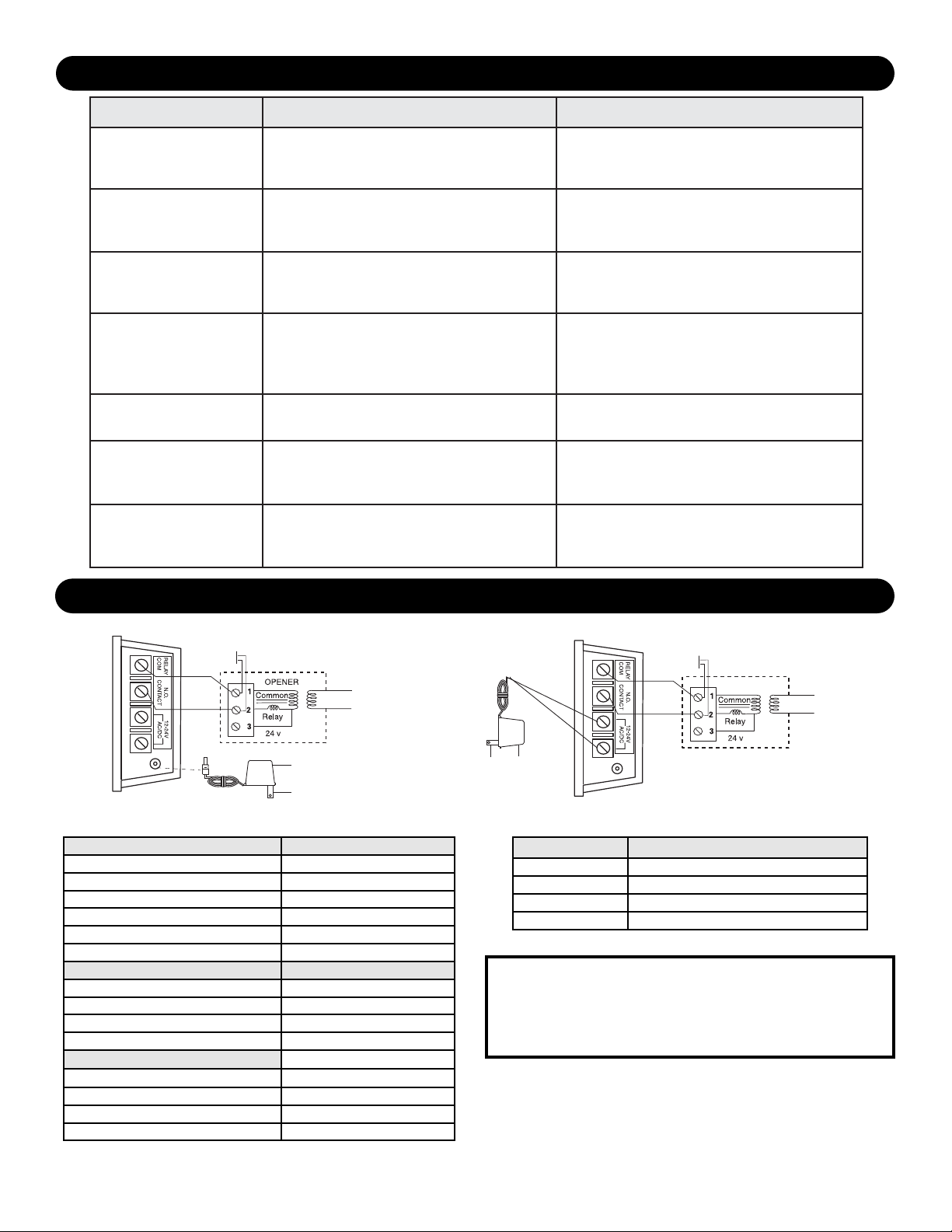
TROUBLESHOOTING GUIDE
ELECTRICAL CONNECTIONS FOR STAR450
Security+®Remote Controls Security+® Keypads
373P 377LM
371LM 379LM
372LM
370LM
373LM
374LM
Passport™ Remote Control Digital Remote Controls
CPT43 361LM
CPT13 362LM
CPT23 363LM
CPT33 333LM
Passport™ Mini Remote Control
CPTK13
CPTK13PH
CPTK33
CPTK33PH
CGI Part Number Description
71-65WTBOX Watertight Box Field Install Kit
86LM Antenna Extension Kit
85LM 24VAC Transformer with Barrel Connector
95LM 24VAC Transformer with Screw Terminals
SERVICE INFORMATION TOLL FREE NUMBER
1-800-528-2806
www.liftmaster.com
Problem Probable Cause(s) Solution(s)
No display 1. Faulty/intermittent power connections
to unit Or
2. No power to unit
No beep when
transmitting
Audible diagnostics may have been
turned OFF (right-most decimal point
will be lit on the display)
Transmitter does
not activate operator
1. Transmitter not learned into system Or
2. Transmitter is blocked Or
3. Transmitter battery is dead
Transmitter will not
learn into memory
1. Memory may be full Or
2. Transmitter may not be a recognized
Chamberlain transmitter Or
3. Transmitter battery is dead
Unit does not function,
[E 1] displayed
Main memory module missing or
damaged
1. Check power connections
to unit
2. Supply power to unit
Press 4 and 0 keys at
the same time
1. Add transmitter to memory
2. Replace transmitter battery
1. Delete unused transmitters from memory
2. Verify transmitter is listed in compatible
transmitters section Or
3. Replace transmitter battery
Replace main memory module
Duplication function
does not work,
Backup memory module missing or
damaged, if included
Replace backup memory module
[E 2] displayed
Keypad does not
respond,
[E 3] displayed
Keypad has a stuck key
Cycle power.
If unit exhibits this condition again after 2
minutes, contact Technical Service.
Receiver (Bottom)
Wall
Button
Trans Primary
Model 85
Transformer
To wall outlet
To wall
outlet
Model 95
Transformer
For highest level of security, we recommend the Security+®and Passport™
transmitter families.
Receiver (Bottom)
Wall
Button
Opener
Trans Primary
 Loading...