

Page 1
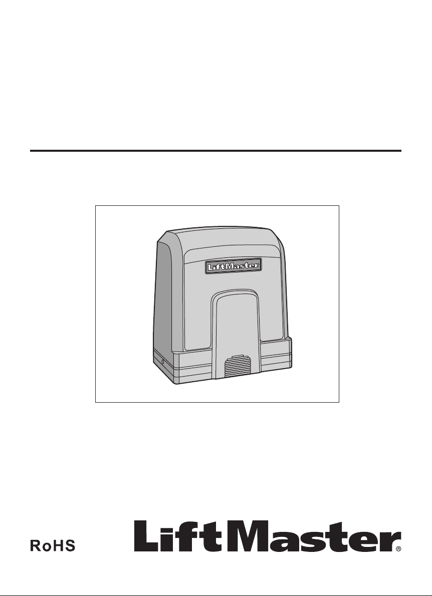
SLIDE GATE OPERATOR
INSTALLATION MANUAL
Models SL600 and SL1000
• PLEASE READ THE MANUAL CAREFULLY BEFORE
INSTALLATION AND OPERATION
• THIS PRODUCT TO BE INSTALLED BY A TRAINED GATE
SYSTEMS TECHNICIAN ONLY.
Page 2

TABLE OF CONTENTS
SAFETY
Safety Precautions For Slide and Ornamental Grill Type Gates ................................................................3
Important Safety Information ............................................................................................................... 4-5
INTRODUCTION
Specifications ...........................................................................................................................................6
Carton Inventory ......................................................................................................................................6
Tools Needed ...........................................................................................................................................7
Overview of Gate Operator .......................................................................................................................7
INSTALLATION
Operator Dimensions ...............................................................................................................................8
Prepare and Install the Mounting Plate .............................................................................................. 8-10
Install the Operator ................................................................................................................................11
Install Limit Switch Bracket ...................................................................................................................11
Disengage the Clutch .............................................................................................................................12
WIRING
Voltage Selection ...................................................................................................................................13
Power Wiring .........................................................................................................................................14
Install Entrapment Protection ...............................................................................................................15
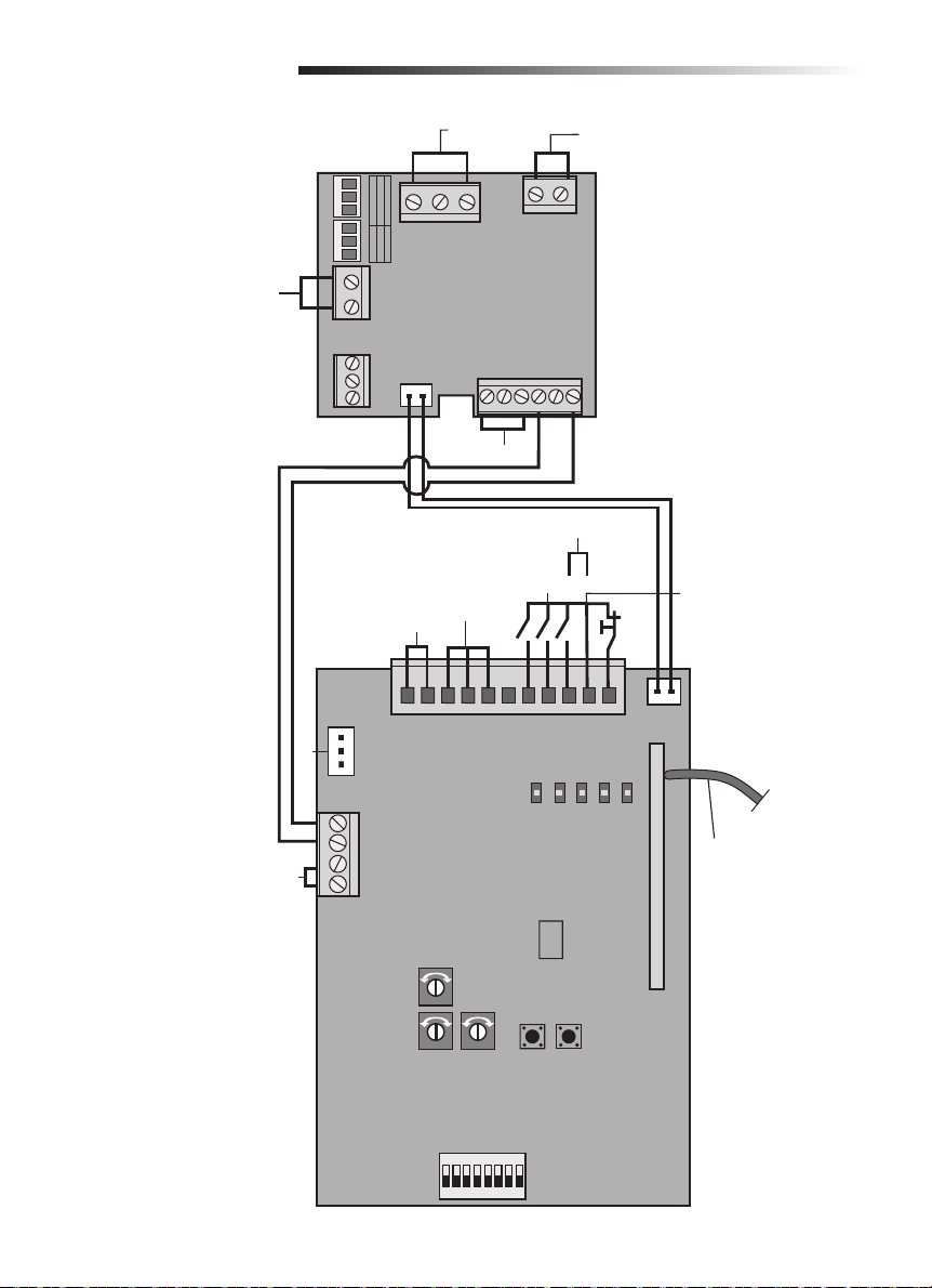
Wiring Diagram ......................................................................................................................................16
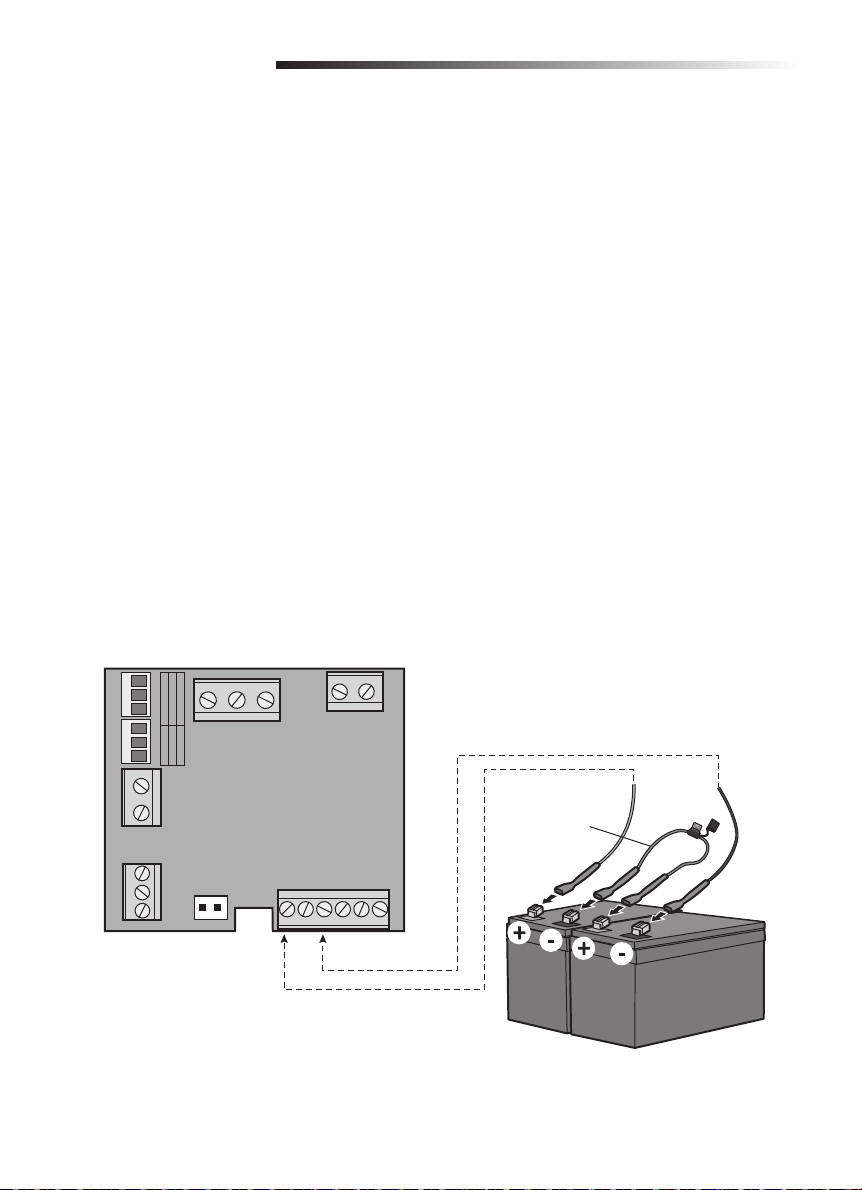
Battery Backup (Optional) ......................................................................................................................17
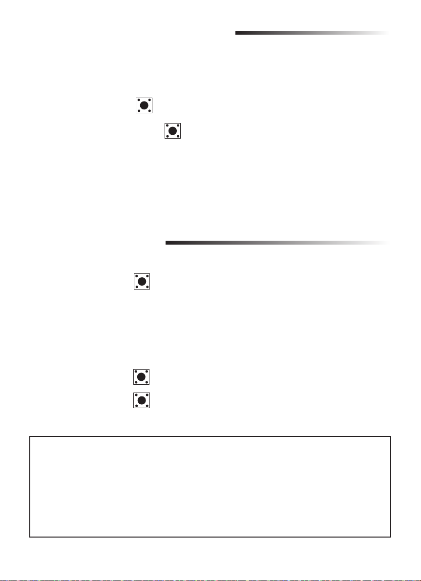
TRAVEL LIMIT SETTINGS ......................................................................................................................18
PROGRAMMING
Remote Control ......................................................................................................................................18
Partial Open Setting ...............................................................................................................................18
Erase All Codes ......................................................................................................................................19
LiftMaster
Erase a LiftMaster
SETTINGS
Increased Starting Force ........................................................................................................................20
Partial Open Setting ...............................................................................................................................20
Auto Closing Setting ..............................................................................................................................20
Limit Switch Setting ...............................................................................................................................20
Force Adjustment ...................................................................................................................................21
Soft Stop Setting ...................................................................................................................................21
Moving Speed Setting ............................................................................................................................21
Opening/Closing Identification ...............................................................................................................21
Flashing Light (Optional) .......................................................................................................................22
Photoelectric Sensor and Edge Sensor Connection ...............................................................................22
OPERATION AND MAINTENANCE .................................................................................................... 23-25
TROUBLESHOOTING .............................................................................................................................26
REPAIR PARTS ......................................................................................................................................27
ACCESSORIES .......................................................................................................................................28
®
Internet Gateway .................................................................................................................19
®
Internet Gateway ....................................................................................................19
2
Page 3
SAFETY
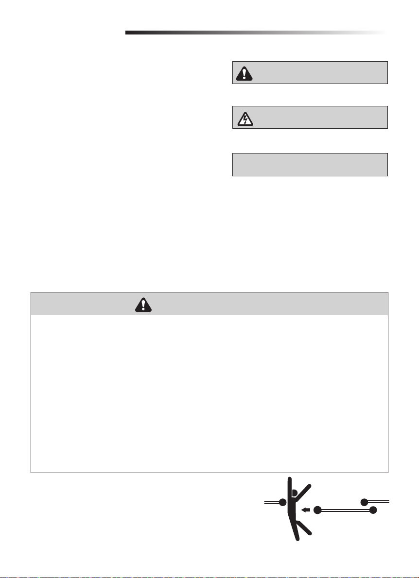
When you see these Safety Symbols and Signal Words on
the following pages, they will alert you to the possibility of
serious injury or death if you do not comply with the warnings
that accompany them. The hazard may come from something
mechanical or from electric shock. Read the warnings carefully.
When you see this Signal Word on the following pages, it will
alert you to the possibility of damage to your gate and/or the gate
operator if you do not comply with the cautionary statements that
accompany it. Read them carefully.
IMPORTANT NOTE:
• BEFORE attempting to install, operate or maintain the operator, you must read and fully understand
this manual and follow all safety instructions.
• These instructions are intended to highlight certain safety related issues. These instructions are
not intended to be comprehensive. Because each application is unique, it is the responsibility of
the purchaser, designer, installer and end user to ensure that the total gate system is safe for its
intended use.
• Save These Instructions.
Safety Precautions For Slide and Ornamental Grill Type Gates
MECHANICAL
ELECTRICAL
To prevent SERIOUS INJURY or DEATH from a moving gate:
• Entrapment protection contact edge sensing device MUST be installed to protect anyone who
may come near a moving gate.
• Locate entrapment protection devices to protect in BOTH the open and close gate cycles.
• Locate entrapment protection devices to protect between moving gate and RIGID objects, such
as posts.
• A gate shall NOT open into public access ways.
• This operator is NOT intended for use by persons (including children) with reduced physical,
sensory or mental capabilities, or lack of experience and knowledge, unless they have been given
supervision or instruction concerning the use of the operator by a person responsible for their
safety.
• Children should be supervised to ensure that they DO NOT play with the operator.
• SAVE THESE INSTRUCTIONS.
3
Page 4
SAFETY
IMPORTANT SAFETY INFORMATION
To reduce the risk of SEVERE INJURY or DEATH from an incorrect installation:
1. Vehicular gate systems provide convenience and security. Gate systems are comprised of many
component parts. The gate operator is ONLY one component. Each gate system is specifically
designed for an individual application.
2. Gate operating system designers, installers and users MUST take into account the possible
hazards associated with each individual application. Improperly designed, installed or maintained
systems can create risks for the user as well as the bystander. Gate systems design and
installation MUST reduce public exposure to potential hazards.
3. A gate operator can create high levels of force in its function as a component part of a gate
system. Therefore, safety features must be incorporated into every design. Specific safety
features include:
• Gate Edges • Guards for exposed rollers • Photoelectric Sensors
• Screen Mesh • Vertical Posts • Instructional and Precautionary Signage
4. Install the gate operator only when:
a. The operator is appropriate for the construction and the usage of the gate.
b. ALL openings of a horizontal slide gate are guarded or screened from the bottom of the gate
to a minimum of 4' (1.2 m) above the ground to prevent a 2 1/4" (6 cm) diameter sphere
from passing through the openings anywhere in the gate, and in that portion of the adjacent
fence that the gate covers in the open position.
c. ALL exposed pinch points are eliminated or guarded, and guarding is supplied for exposed
rollers.
5. The operator is intended for installation on gates used for vehicles. Pedestrians should be
supplied with a separate access opening.
6. The gate MUST be installed in a location so that enough clearance is supplied between the gate
and adjacent structures when opening and closing to reduce the risk of entrapment.
7. The gate MUST be properly installed and work freely in both directions prior to the installation
of the gate operator.
8. Controls MUST be far enough from the gate so that the user is prevented from coming in
contact with the gate while operating the controls.
9. BEFORE installing the drive, check that the driven part is in good mechanical condition, correctly
balanced and opens and closes properly.
4
Page 5
SAFETY
IMPORTANT SAFETY INFORMATION
10. For a gate operator utilizing a non-contact sensor:
a. Reference owner’s manual regarding placement of non-contact sensor for each type of
application.
b. Care shall be exercised to reduce the risk of nuisance tripping, such as when a vehicle trips
the sensor while the gate is still moving.
c. One or more non-contact sensors shall be located where the risk of entrapment or
obstruction exists, such as the perimeter reachable by a moving gate or barrier.
11. For a gate operator utilizing a contact sensor such as an edge sensor:
a. A hard wired contact sensor shall be located and its wiring arranged so the communication
between the sensor and the gate operator is not subject to mechanical damage.
b. A wireless contact sensor such as the one that transmits radio frequency (RF) signals to the
gate operator for entrapment protection functions shall be located where the transmission of
the signals are not obstructed. A wireless contact sensor shall function under the intended
end-use conditions.
c. One or more contact sensors shall be located at the leading edge, trailing edge and post
mounted both inside and outside of a vehicular horizontal slide gate.
d. One or more contact sensors shall be located on the inside and outside leading edge of a
gate. Additionally, if the bottom edge of a gate is greater than 6" (15 cm) above the ground at
any point in its arc of travel, one or more contact sensors shall be located on the bottom
edge.
12. For horizontally moving pedestrian doors, ensure that entrapment between the driven part and
the surrounding fixed parts due to the movement of the driven part is avoided. This can be
achieved if the relevant distance does not exceed 8 mm. However, the following distances are
considered sufficient to avoid entrapments for the parts of the body identified:
a. For fingers, a distance greater than 25mm
b. For feet, a distance greater than 50mm
c. For heads, a distance greater than 300mm
d. For the whole body, a distance greater than 500mm
If these distances cannot be achieved, safeguarding devices must be provided.
IMPORTANT:
and Chile.
The MyQ feature and its accessories are not permitted for use in the countries of Peru
5
Page 6
INTRODUCTION
Specifications
Main AC Supply: 110-127Vac / 220-240Vac; 50/60Hz
Motor Voltage:
Input Power:
Ambient Temperature Range:
Maximum Gate Weight:
Maximum Gate Width:
Maximum Pull Force (N):
Protection Level: IP 44
Travel Speed:
Daily Cycle Rate: Maximum 50 cycles per day
Gate Operator Weight:
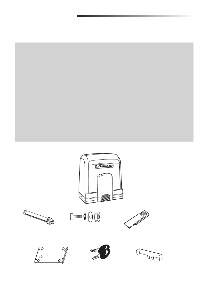
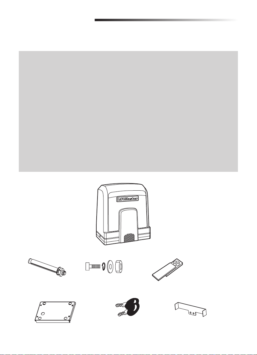
Carton Inventory
24 Vdc
100 W
-20 ~ +50 ˚C
600 Kg (Model SL600)
1000 Kg (Model SL1000)
8 m
780 (Model SL600)
970 (Model SL1000)
22 cm/s
6 Kg
M8x80 Expanding screw (4)
Mounting plate
M8 X40 Screw with
hexagon nut and plain
washer (4 sets)
Release key (2)
Gate Operator
Installation
Manual
(Not shown)
Remote Control, model TX4UNI (2)
Limit switch bracket (2)
6
Page 7
INTRODUCTION
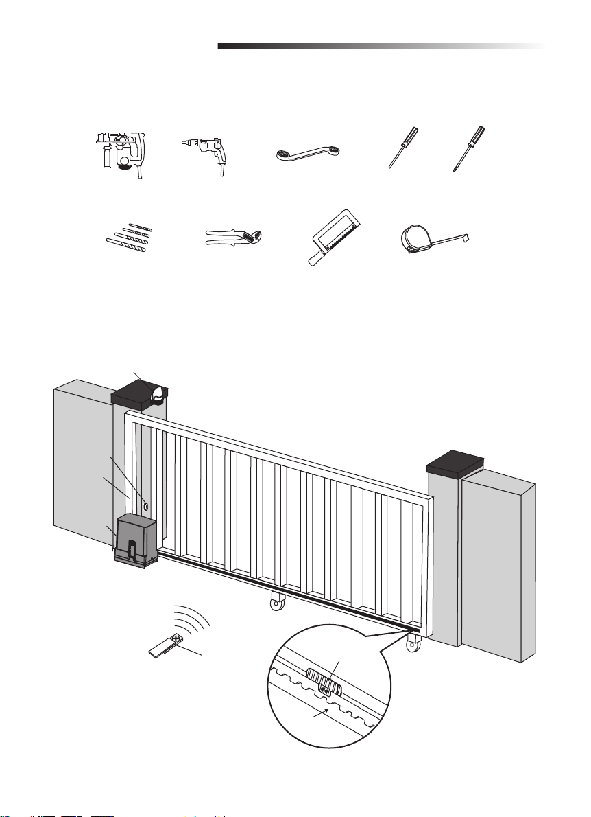
Tools Needed
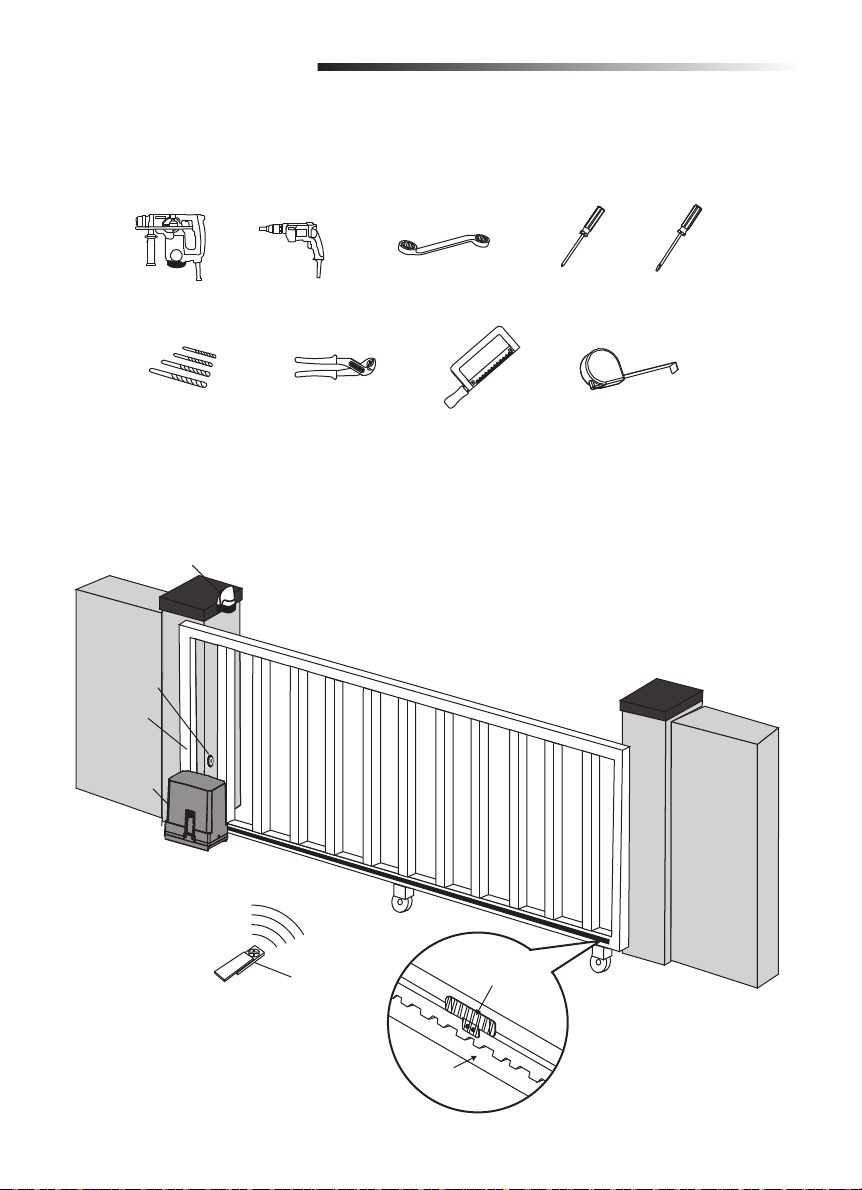
Overview of Gate Operator
Cables used must meet all National and Local Codes for outdoor use.
Flashing Light
Photoelectric
Sensor
Gate
Gate
Operator
Remote
Control
Limit
Switch Bracket
Rack
7
Page 8
INSTALLATION
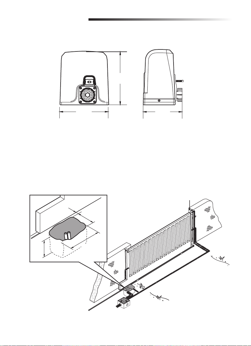
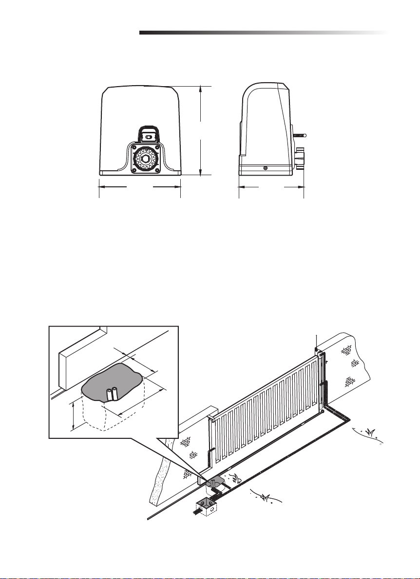
Operator Dimensions
294 mm
270 mm
218 mm
Prepare and Install the Mounting Plate
The instructions and illustrations in this manual are examples ONLY. Your installation may vary
depending on space, obstructions, and accessories. It is up to the installer to select the most suitable
solution.
1. Dig a hole to the side of the gate (Figure 1). The concrete pad should be deeper than the frost line.
Check all national and local codes.
Figure 1
30.47 cm
(12")
3.98 cm
(1.57")
23.97 cm
(9.44")
39.97 cm
(15.74")
8
Page 9
INSTALLATION
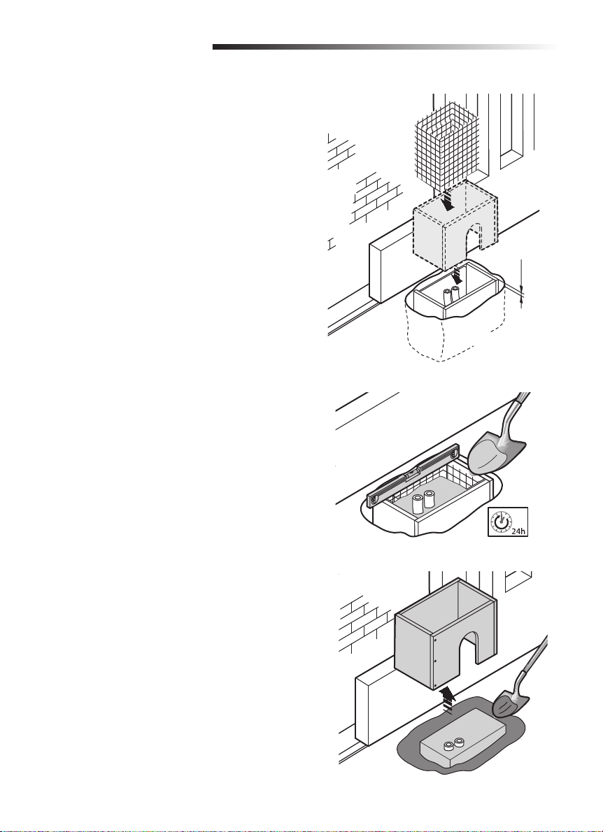
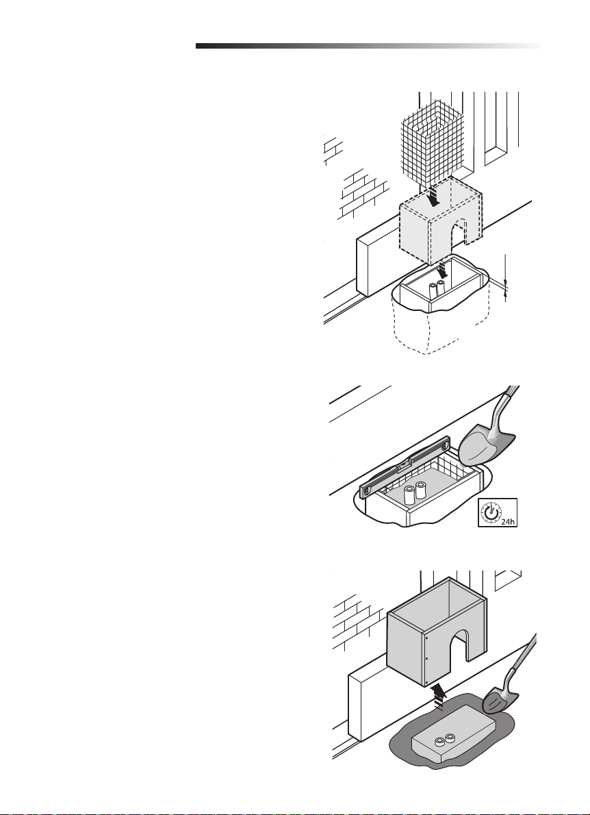
2. Prepare a trench and install the electrical
conduit. All conduit should be 3/4" diameter
maximum.
NOTE: The number of conduits will depend on
your site and the accessories to be installed.
3. Prepare a form box larger than the mounting
plate and insert the form box in the hole
(Figure 2). The form box should be 1-3/4" (50
mm) above the ground (Figure 2).
4. Insert an iron grid inside the form to reinforce
the concrete (Figure 2).
5. Fill the form box with concrete and wait for at
least 24 hours to allow the concrete to cure
(Figure 3).
Figure 2
1-3/4" (50 mm)
Figure 3
6. Remove the form box (Figure 4).
7. Fill the hole around the concrete form with soil
(Figure 4).
Figure 4
9
Page 10
INSTALLATION
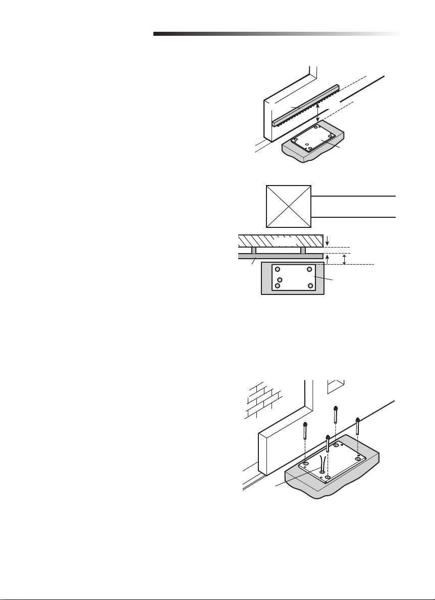
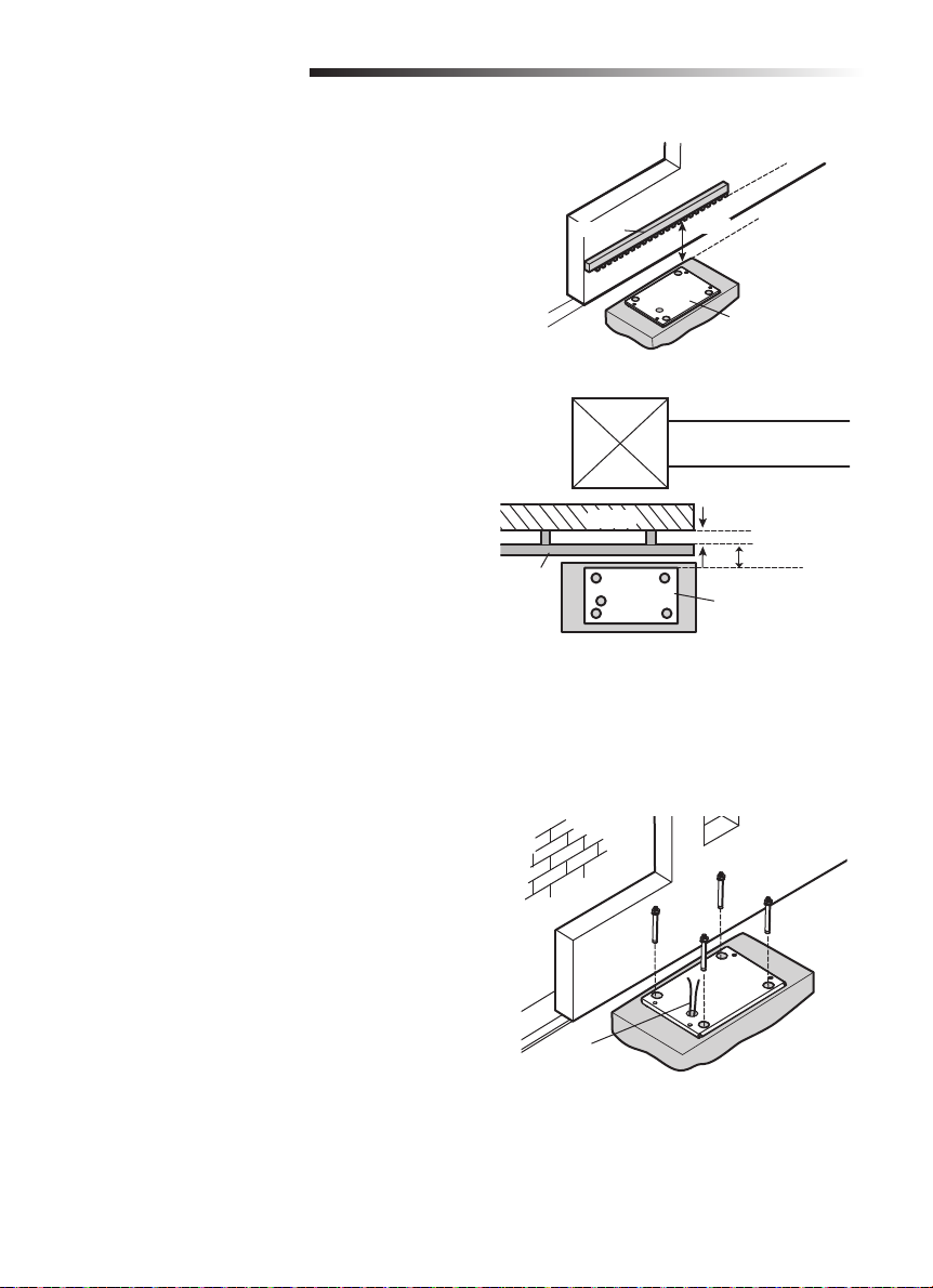
8. Position the mounting plate relative to the gate
(Figure 5).
Figure 5
TOP VIEW OF GATE
Rack
Rack
Gate
11 cm
Mounting Plate
The distance between
the rack and the gate
should be 2.4 cm.
3 cm
Mounting Plate
9. Run all cables through the knockout (Figure 6).
10. Mark the mounting hole locations, drill with
a masonry bit. Screw the mounting plate into
place with provided anchoring hardware
(Figure 6).
Figure 6
Cables
10
Page 11
INSTALLATION
Install the Operator
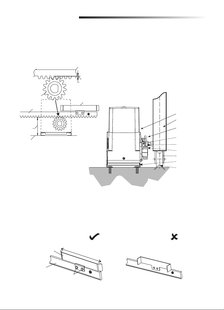
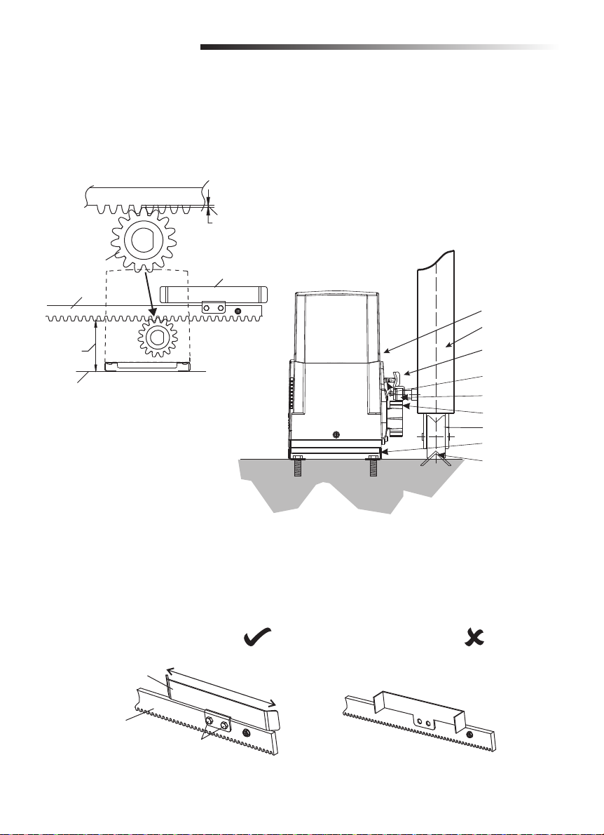
Make sure the sliding gate can be moved smoothly before installation. There must be a clearance
between rack and gear as shown, or the gate movement may be effected.
2-3 mm
Gear
Rack
110 mm
Ground level
Limit switch
bracket
Operator
Gate
Limit switch
bracket
Limit switch
spring
Rack
Gear
Wheel
Mounting plate
Track
Limit Switch Bracket Installation
Attach the limit switch bracket to the rack with adjusting screws. If the limit switch bracket is installed
incorrectly, the gate cannot learn the travel limit.
CORRECT INSTALLATION
Limit switch bracket
Adjust the limit
switch bracket
INCORRECT INSTALLATION
Rack
Adjusting screw
11
Page 12
INSTALLATION
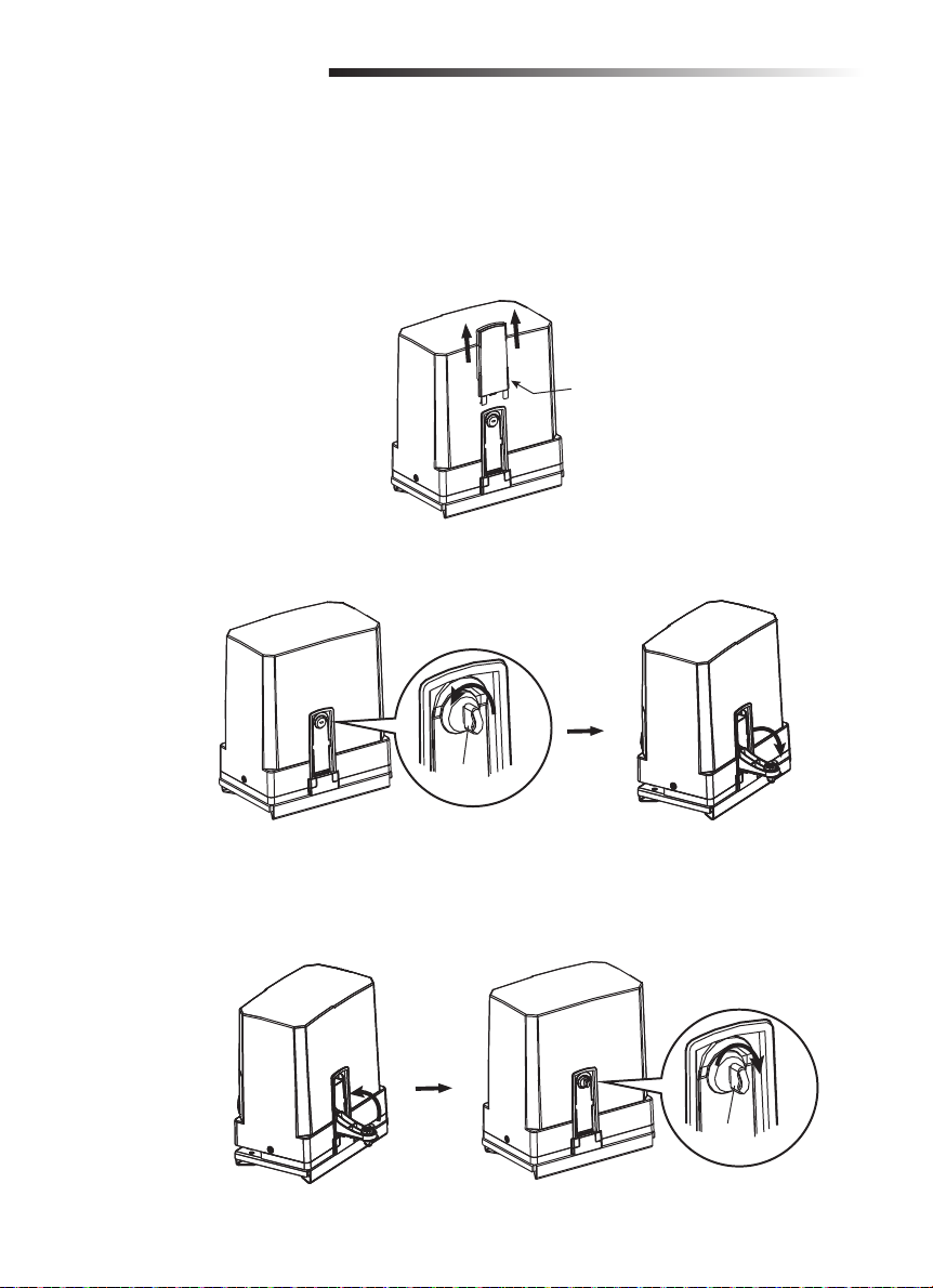
Disengage the Clutch
Disengaged the clutch for the following reasons:
• To open or close the gate manually in case of power failure.
• To reset the functions.
• The operator needs maintenance.
1. Pull out the key guard.
Key guard
2. Turn the release key, then pull manual release lever down to disengage the clutch.
Release key
Disengage
the clutch
3. To re-engage the clutch, return the manual release lever to the upright position making sure the
housing and release lever tabs are aligned and turn the release key to the lock position.
NOTE: Remember to lock the clutch after cover is in place and all operations are fi nished.
Lock the clutch
Release key
12
Page 13
WIRING
To reduce the risk of SEVERE INJURY or DEATH:
• ANY maintenance to the operator or in the area near the operator MUST NOT be performed until
disconnecting the electrical power (AC or solar and battery). Upon completion of maintenance
the area MUST be cleared and secured, at that time the unit may be returned to service.
• Disconnect power at the fuse box BEFORE proceeding.
NOTE: The operator should be on a separate fused line of adequate capacity.
• ALL electrical connections MUST be made by a qualified individual.
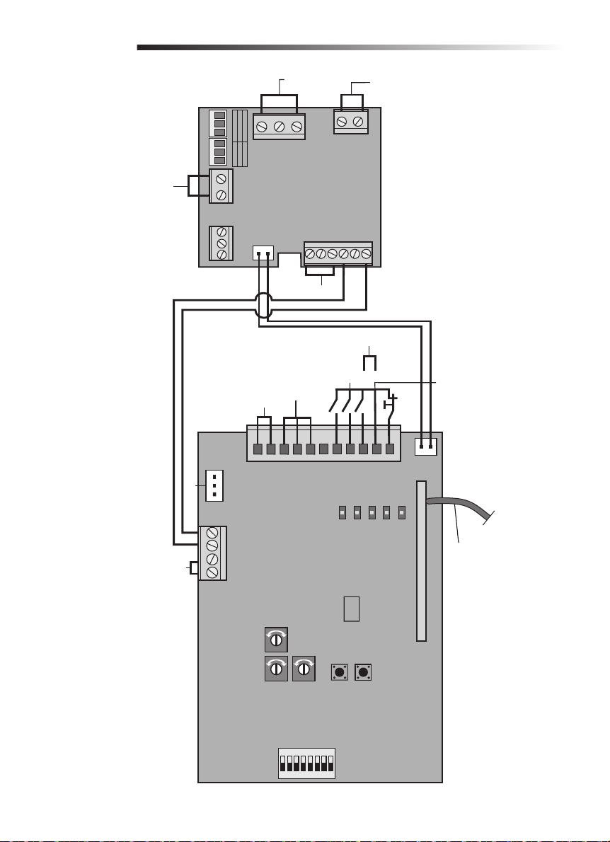
• DO NOT install any wiring or attempt to run the operator without consulting the wiring diagram.
• ALL power wiring should be on a dedicated circuit and well protected.
• ALL power and control wiring MUST be run in separate conduit.
• BEFORE installing power wiring or control stations be sure to follow all specifications and
warnings described below. Failure to do so may result in SEVERE INJURY to persons and/or
damage to operator.
Voltage Selection
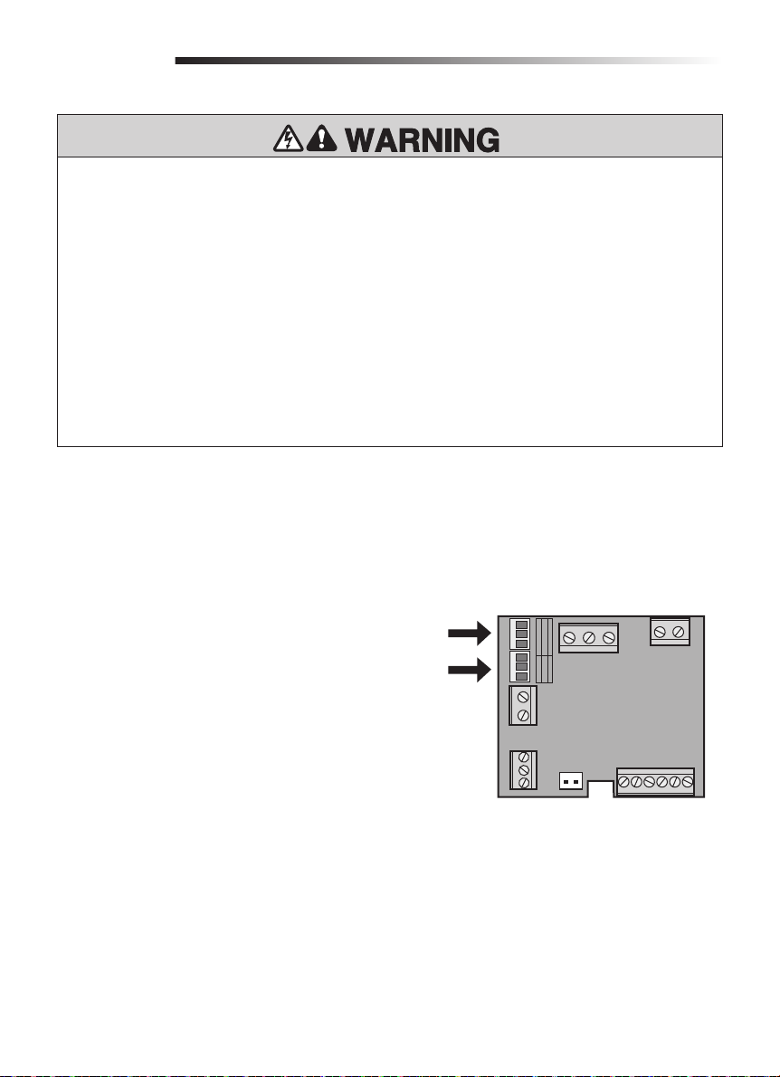
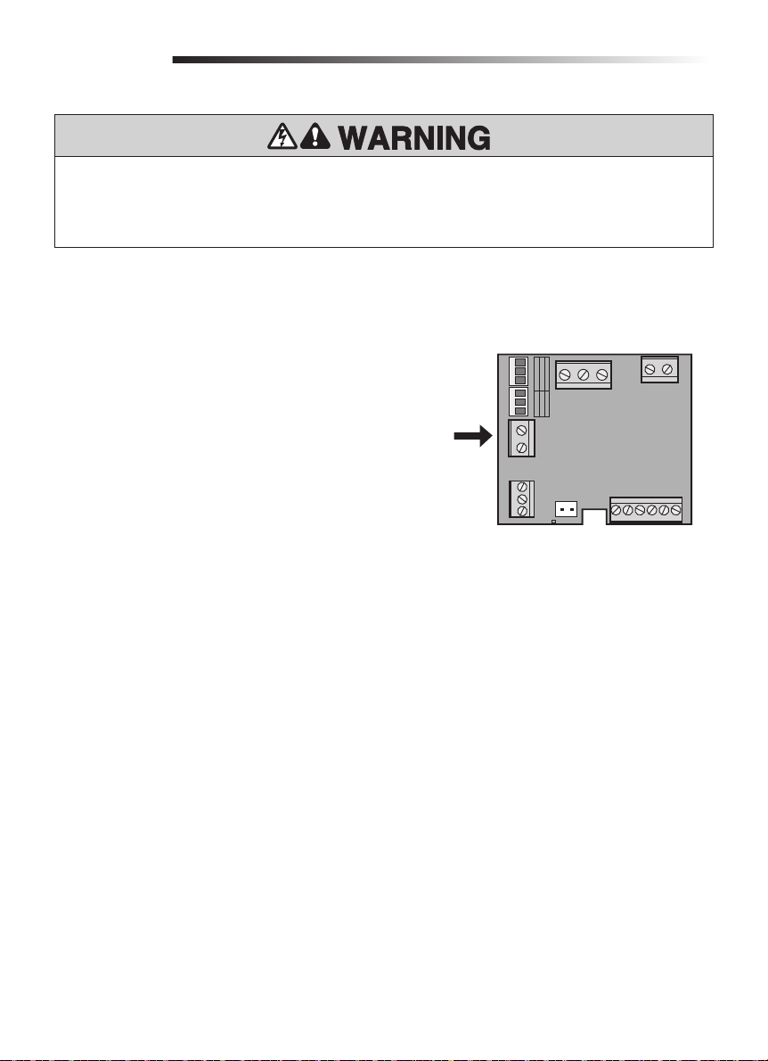
The operator can be wired for either 110-127 Vac or 220-240 Vac through a jumper setting.
NOTE: Factory default jumper is installed for 220 Vac.
For 110-127 Vac installations:
1. Turn off the AC power from the main power
source circuit breaker.
2. Place the jumper on J3 and the cover on J2 on
the power board.
For 220-240 Vac installations:
1. Turn off the AC power from the main power
source circuit breaker.
2. Place the jumper on J2 and the cover on J3 on
the power board.
13
J3
J2
J3 J2
NL
POWER LINE
PE
CN7
POWER BOARD
230V
J2
J3
110-127Vac 220-240Vac
OFF
ON
OFF
ON
CN6
CN2
CHCTR VBAT
127V
N
CN3
TR IN
CN1
BAT
TR OUT
CN4
+
DC
Page 14
WIRING
To reduce the risk of SEVERE INJURY or DEATH:
• DO NOT TOUCH the unused connections on J2 or J3 as they are energized.
• Replace cover before reconnecting or connecting power.
Power Wiring
The operator can be wired for either 110-127 Vac or 220-240 Vac.
1. Turn off the AC power from the main power
source circuit breaker.
2. Insert the AC power wires through the wire
input hole closest to the motor.
3. Connect the “hot” wire to the L terminal on the
power board.
4. Connect the neutral wire to the N terminal on
the power board.
5. Tighten the watertight connector nut.
6. Restore power to the operator.
Power In
J3 J2
NL
POWER LINE
PE
CN7
J2
J3
110-127Vac 220-240Vac
OFF
ON
OFF
ON
CN6
CN2
CHCTR VBAT
POWER BOARD
N
127V
230V
CN3
TR IN
CN1
BAT
TR OUT
CN4
+
DC
14
Page 15
WIRING
To prevent SERIOUS INJURY or DEATH from a moving gate:
• Entrapment protection devices MUST be installed to protect anyone who may come near a
moving gate.
• Locate entrapment protection devices to protect in BOTH the open and close gate cycles.
• Locate entrapment protection devices to protect between moving gate and RIGID objects, such as
posts or walls.
Install Entrapment Protection Devices
Refer to Accessories page for the approved list of entrapment protection devices.
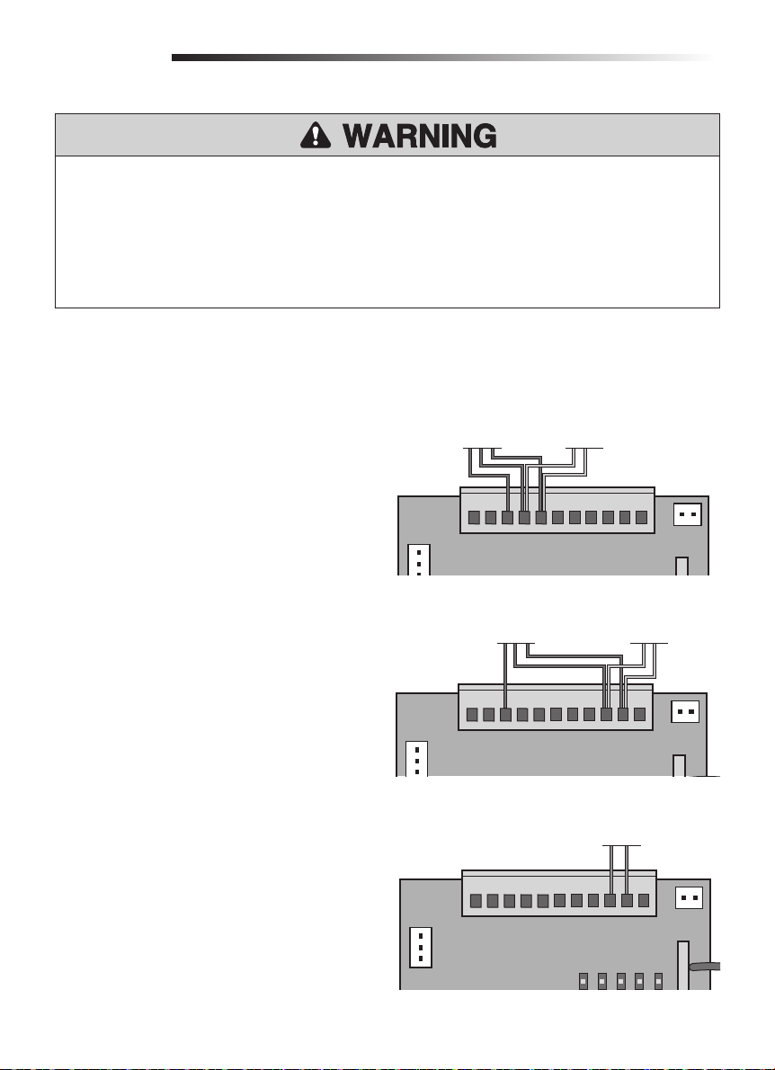
IR1 Functionality
PHOTOELECTRIC SENSORS
The photoelectric sensor will function differently
depending on if it is connected to the IR1 or IR2
input. Refer to the "Settings" section on page 22 for
an explanation of the functionality.
1. Remove the factory jumper from the IR1 or IR2
input.
2. Connect the photoelectric sensor receiver to
IR1 and GND or IR2 and GND, depending on
the desired functionality.
3. Connect the photoelectric sensor transmitter to
IR+24V, IR1, and GND or to IR+24V, IR2, and
GND.
Photoelectric
Sensor Transmitter
CN3
Sensor Transmitter
CONTROL BOARD
DCLAMP
+24V
Photoelectric
Photoelectric
Sensor Receiver
GND
IR+24V
IR1
IR2 Functionality
CONTROL BOARD
IR2
SW2
SW1
Photoelectric
Sensor Receiver
GND
CN2
STOP
EDGE SENSOR
The Edge sensor can only be connected to the IR2
input.
1. Remove factory jumper from IR2 to GND.
2. Connect the edge sensor to IR2 and GND.
CONTROL BOARD
CN4
15
CN3
DCLAMP
+24V
IR+24V
GND
SW2
SW1
IR1
CN2
STOP
IR2
GND
Edge Sensor
CN3
DCLAMP
+24V
IR+24V
GND
SW2
SW1
IR1
LED1
IR2
LED2
GND
LED3
STOP
LED4
CN2
LED5
Page 16
WIRING
POWER IN
J3 J2
NL
POWER LINE
Transformer
(Input)
127V
N
230V
J2
J3
110-127Vac 220-240Vac
OFF
ON
OFF
ON
CN6
TR IN
CN1
Transformer
(Out)
CN3
TR OUT
POWER BOARD
CONTROL BOARD
PE
Operator
M1M2
Operator
CN7
DC Flashing
Light
CN4
CN1
CN3
MOTOR DC
CN2
CHCTR VBAT
+24V
RV
FORCE
BAT
Backup Battery
Photoelectric Sensor or Edge
Photoelectric
Limit Switch
Sensor
DCLAMP
GND
IR+24V
SW1
IR1
LEARN
S2
LV
LED1
SW2
SBC
IR2
LED2
CN4
+
DC
Emergency Stop
Switch
CN2
STOP
GND
LED3
LED4
LED5
RF
Antenna
SBC is an
open/close
S1
command for a
single gate.
ON
12345678
16
ON
Page 17
WIRING
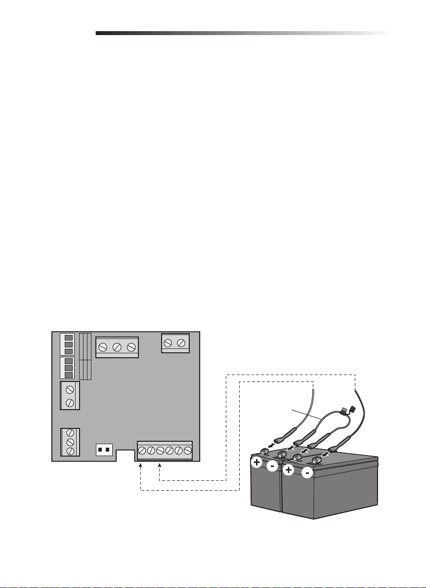
Battery Backup (Optional)
The batteries are charged in the circuit by the integrated transformer. Recommended items for a battery
backup application (not provided):
• Two 12V 4Ah batteries (McNair Model RB-FM-12V-4AH)
• Battery box (Attwood Model 9069-1)
• 3 x 18 AWG (1.00 mm) VM-1 105˚C 600V, 1 wire must have a 10A/250V in-line fuse
1. Disconnect AC power to the operator.
2. Insert the battery power wires through the same hole as the AC power wires.
3. Connect the battery cable to the BATTERY terminals on the power board.
4. Install battery box in desired location (no further than 10 feet from the operator).
5. Place the batteries in the battery box.
6. Connect a jumper with an in-line fuse between the positive (+) terminal on one battery and the
negative (-) terminal on the other battery.
7. Connect the positive battery cable wire to the positive (+) terminal on the battery.
8. Connect the negative battery cable wire to the negative (-) terminal on the other battery.
9. Reconnect AC power to the operator.
10. Place cover on the operator.
J2
J3
J3 J2
NL
POWER LINE
PE
110-127Vac 220-240Vac
OFF
ON
OFF
ON
CN6
CN7
POWER BOARD
CN2
CHCTR VBAT
230V
N
127V
TR IN
CN1
+-
BAT
CN3
TR OUT
Jumper with
10A/250V
in-line fuse
(not provided)
CN4
+
DC
17
Page 18
TRAVEL LIMIT SETTINGS
The travel limits can be set when the gate is closed or opened.
SBC
1. Press and hold the
button for 5 seconds. The DL5 will fl ash.
2. Press the remote control or
SBC
button.
3. The gate will open or close and stop when the limit switch bracket reaches the switch spring. The
gate operator will save the setting information.
The operator should move in the close direction fi rst when setting the limits. If the gate moves in the
open direction fl ip the #5 dip switch to the opposite position.
NOTE: The gate operator will exit programming after 30 seconds of inactivity.
PROGRAMMING
Remote Control
1. Press and release the
2. Press the remote control button that you would like to program.
The operator will automatically exit learn mode (LED1 will fl ash and go out) if programming is
successful. To program additional Security+ 2.0™ remote controls or remote control buttons, repeat
the programming steps above. Press the LEARN button a second time to exit programming at any time.
Partial Open Setting
1. Press and release the
LEARN
button, LED1 will light.
LEARN
button, LED1 will light.
2. Press and release the
LEARN
button again, LED1 will begin fl ashing.
3. Press the remote control button that you would like to program to the partial open setting (must be
different than button controlling normal operation).
NOTICE: Operation is subject to the following two conditions: (1) this device may not cause harmful interference, and (2) this device must accept any
interference received, including interference that may cause undesired operation.
Any changes or modifi cations not expressly approved by the party responsible for this product could void the user’s authority to operate the equipment.
This device is designed to provide reasonable protection against harmful interference in a residential installation. This equipment generates, uses
and can radiate radio frequency energy and, if not installed and used in accordance with the instructions, may cause harmful interference to radio
communications. However, there is no guarantee that interference will not occur in a particular installation. If this equipment does cause harmful
interference to radio or television reception, which can be determined by turning the equipment off and on, the user is encouraged to try to correct the
interference by one or more of the following measures:
- Reorient or relocate the receiving antenna.
- Connect the equipment into an outlet on a circuit different from that to which the receiver is connected.
- Consult the dealer or an experienced radio/TV technician for help.
18
Page 19

PROGRAMMING
Erase All Codes
1. Press and hold the
2. Hold the LEARN button for approximately 8 seconds. LED1 will go out and all remote control codes
are now erased.
LiftMaster® Internet Gateway
IMPORTANT: The MyQ feature, Internet Gateway and its accessories are not permitted for use in the
countries of Peru and Chile.
To program the operator to the LiftMaster
1. Connect the Ethernet cable to the LiftMaster
2. Connect power to the LiftMaster
3. Create an online account by visiting www.myliftmaster.com.
4. Register the LiftMaster
5. Use an internet enabled computer or smartphone to add devices. The LiftMaster
will stay in learn mode for three minutes.
6. Press the LEARN button on the operator (LED1 will light as it enters learn mode). The LiftMaster
Internet Gateway will pair to the operator if it is within range and LED1 will fl ash and go out if
programming is successful.
LEARN
button, LED2 will light.
®
®
Internet Gateway.
®
Internet Gateway.
Internet Gateway:
®
Internet Gateway and the router.
®
Internet Gateway
®
Erase a LiftMaster® Internet Gateway
1. Press and hold the
2. Hold the LEARN button for approximately 8 seconds. LED1 will go out and all remote control codes
are now erased.
3. Press and hold the LEARN button a second time, LED1 will light again.
4. Hold the LEARN button for approximately 8 seconds. LED1 will go out and all gateways are now
erased.
LEARN
button, LED1 will light.
19
Page 20
SETTINGS
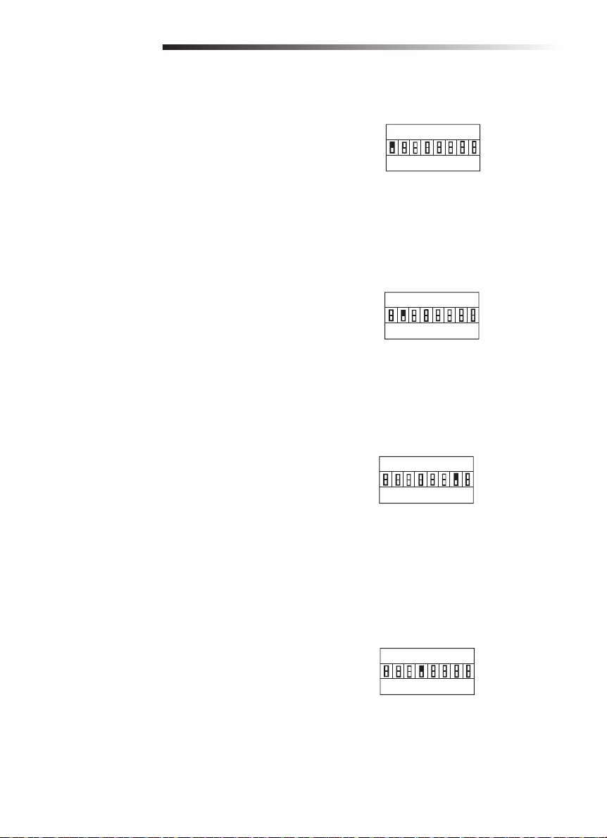
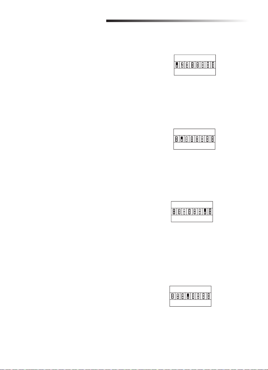
Increased Starting Force
When activated, the operator will run with higher
force for fi rst 2+/-1 seconds than the normal
running force.
1 ON = Higher starting force
1 OFF = Standard starting force
Partial Open Setting
When on, the partial open setting will open the
gate 1 meter. Refer to the Programming section for
instructions to program the remote control for this
setting.
2 ON = Partial Open ON
2 OFF = Partial Open OFF
Auto Closing Setting
Switches shall be used to set timer to close
duration from 0-105 seconds by adding the values
of each switch in the ON position. Each switch
value shall be the following:
6 ON = 15 seconds
7 ON = 30 seconds
8 ON = 60 seconds
1 2 3 4 5 6 7 8
ON
S1
OFF
Increased Starting Force is on
1 2 3 4 5 6 7 8
ON
S1
OFF
Partial Open is on
1 2 3 4 5 6 7 8
ON
S1
OFF
30 Seconds
Limit Switch Setting
Factory default is set to OFF (normal open).
4 ON = Travel limit switch is set to
normal close
4 OFF = Travel limit switch is set to
normal open
1 2 3 4 5 6 7 8
ON
S1
OFF
Normal open
20
Page 21
SETTINGS
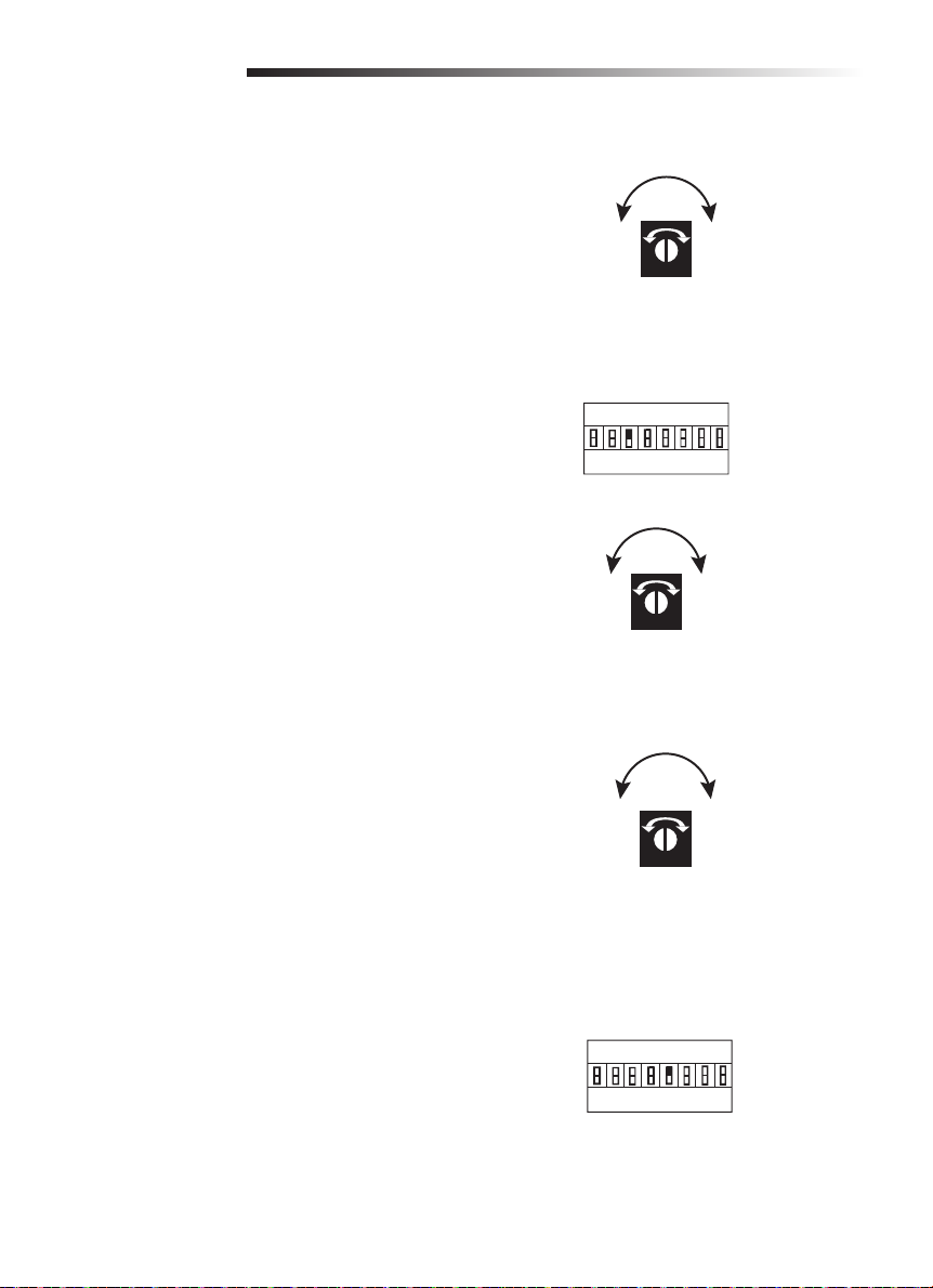
Force Adjustment
The gate will stop when it contacts an obstacle in
opening, and will reverse to open when in closing.
If the force is set too weak, the gate will not work
normally. If the force is set too strong, it may cause
serious injury or property damage.
Turn the FORCE dial clockwise to increase the force
of the gate. Turn the FORCE dial counterclockwise
to decrease the force of the gate.
IncreaseDecrease
FORCE
Soft Stop Setting
For the soft stop function, the gate stops softly
before the opening/closing motion is almost
fi nished.
3 ON = Soft stop function is 3 seconds
3 OFF = Soft stop function is 4 seconds
Turn LV dial clockwise to increase the soft stop
speed. Turn the LV dial counterclockwise to
decrease the soft stop speed.
Moving Speed Setting
Turn RV dial clockwise to increase the speed of the
gate. Turn the RV dial counterclockwise to decrease
the speed of the gate.
Opening/Closing Identification
If the gate reacts incorrectly to an obstacle, set
dip switch 5 to the opposite position to reset the
correct gate position.
Correct: When the gate is closing, and the
photoelectric sensor beam is interrupted or the
gate meets an obstacle, the gate will immediately
reverse to the open position.
Incorrect: When the gate is closing, and the
photoelectric sensor beam is interrupted or the gate
meets an obstacle, the gate stops immediately or
continues to close.
1 2 3 4 5 6 7 8
ON
S1
OFF
Soft stop function is on
IncreaseDecrease
LV
IncreaseDecrease
RV
1 2 3 4 5 6 7 8
ON
S1
OFF
21
Page 22

SETTINGS
Flashing Light (Optional)
The DC LAMP and GND connectors on the control board are for the FA42LM fl ashing light. The fl ashing
light will turn on before the gate opens.
Photoelectric Sensor and Edge Sensor Connection
The connection for the photoelectric sensor and edge sensor is normally closed.
PHOTOELECTRIC SENSOR
Photoelectric sensors can be connected to IR1 or IR2.
When the beam of a photoelectric sensor connected to IR1 is interrupted by obstacles, the gate will stop
and reverse during closing or stop during opening. IR1 LED on the control board will turn off. When
the beam of a photoelectric sensor connected to IR2 is interrupted by obstacles, the gate will stop and
reverse for 1 second during closing or stop during opening. IR2 LED on the control board will turn off.
EDGE SENSOR
Edge sensors can only be connected to IR2.
When the edge sensor connected to IR2 is contacted, the gate will stop and reverse for 1 second during
closing or stop during opening. IR2 LED on the control board will turn off.
22
Page 23
OPERATION AND MAINTENANCE
Important Safety Instructions
• READ AND FOLLOW ALL INSTRUCTIONS.
• NEVER let children operate or play with gate controls. Keep the remote control away from
children.
• ALWAYS keep people and objects away from the gate. NO ONE SHOULD CROSS THE PATH OF
THE MOVING GATE.
• Test the gate operator monthly. The gate MUST reverse on contact with a rigid object or stop
when an object activates the non-contact sensors. After adjusting the force or the limit of travel,
retest the gate operator. Failure to adjust and retest the gate operator properly can increase the
risk of INJURY or DEATH.
• Use the emergency release ONLY when the gate is NOT moving.
• KEEP GATES PROPERLY MAINTAINED. Read the owner’s manual. Have a qualified service person
make repairs to gate hardware.
• The entrance/exit is intended for vehicles. Pedestrians should be supplied with a separate access
opening.
• Activate gate ONLY when it can be seen clearly, is properly adjusted and there are no obstructions
to gate travel.
• Locate entrapment protection devices to protect in BOTH the open and close gate cycles.
• This operator is NOT intended for use by persons (including children) with reduced physical,
sensory or mental capabilities, or lack of experience and knowledge, unless they have been given
supervision or instruction concerning the use of the operator by a person responsible for their
safety.
• Children should be supervised to ensure that they DO NOT play with the operator.
• SAVE THESE INSTRUCTIONS.
23
Page 24
OPERATION AND MAINTENANCE
Maintenance
To reduce the risk of SEVERE INJURY or DEATH:
• Disconnect ALL power BEFORE performing ANY maintenance.
• ALL maintenance MUST be performed by a LiftMaster
• ALWAYS wear protective gloves and eye protection when changing the battery or working around
the battery compartment.
• If the supply cord is damaged, it MUST be replaced by the manufacturer, its service agent or
similarly qualified persons in order to avoid a hazard.
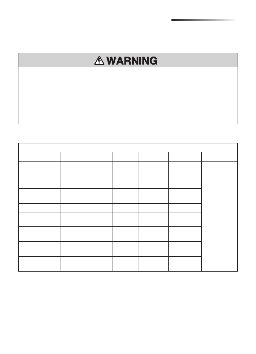
Maintenance Chart
DESCRIPTION TASK MONTH 3 MONTHS 6 MONTHS 12 MONTHS
External
entrapment
protection
systems
Gate warning
signs
Manual release Check and operate •
Gate Inspect for wear or
Accessories Check all for proper
Electrical Inspect all wire
Total unit Inspect for wear or
Check for proper
operation
Make sure they are
present
damage
operation
connections
damage
®
professional.
CHECK AT LEAST ONCE EVERY
•
•
•
•
•
•
Complete Check Out
24
Page 25
OPERATION AND MAINTENANCE
Recycling
Lead-acid backup battery and some electronic material are harmful substances. In order not to get
the environment polluted, they should be recycled or discarded according to requirements of the
local law regulation.
There are different kinds of materials in a gate operator. Some can be recycled, such as aluminum, iron,
plastic, wires etc., not all materials are recyclable.
1. Completely disconnect all power to the operator.
2. Disassemble all the equipment and accessories.
3. Remove the backup battery from the operator and the battery in the remote control.
4. Take out the control board.
5. Recyclable materials should be handled by the local qualifi ed company.
6. Backup battery, battery from remote control and control board, etc. with harmful substances
should be handled by the local qualifi ed company to prevent environmental pollution.
25
Page 26

TROUBLESHOOTING
Trouble Cause Solution
The operator will not
work from the remote
control.
When opening or
closing the gate, the
gate does not stop
when the block touches
the limit switch.
The gate does not
reverse when meeting
obstacles.
The gate opens
automatically during the
closing procedure.
The gate opens
automatically when
the door is completely
closed.
The gate does not open
completely.
1. The plug is not securely
connected.
2. The clutch is disengaged.
3. Photoelectric sensor or
edge sensor malfunction.
4. The fuse is blown.
5. The remote control code
has been erased.
6. The remote control battery
power is too weak or dead.
1. The SW1 and SW2 terminal
connections are reversed.
2. The motor wire connections
are reversed.
1. The gate closing direction
has been set incorrectly.
2. The force is set too high.
The force is set too low. Turn the force setting dial clockwise to
The gate closing direction
has been reversed and the
automatic closing gate
function is active.
The user controls the gate by
partial open button in error.
1. Have the power supply connected
securely by a qualifi ed technician.
2. Engage the clutch with the release
key.
3. Check the photoelectric sensors and
edge sensors. If the photoelectric
sensors or edge sensors are
damaged, replace with a new pair. If
no sensors are installed, connect the
GND terminal and IR terminal with a
short cable.
4. Replace the fuse.
5. Reprogram the remote control.
6. Replace the remote control battery.
1. Switch the SW1 and SW2 terminal
connections.
2. Switch the motor wire connections.
1. Set dip switch 5 to the opposite
position.
2. Turn the force setting dial
counterclockwise to adjust the force to
a proper level.
adjust the force to a proper level.
Set dip switch 5 to the opposite position.
Control the gate by pressing full
opening/closing button.
26
Page 27
REPAIR PARTS
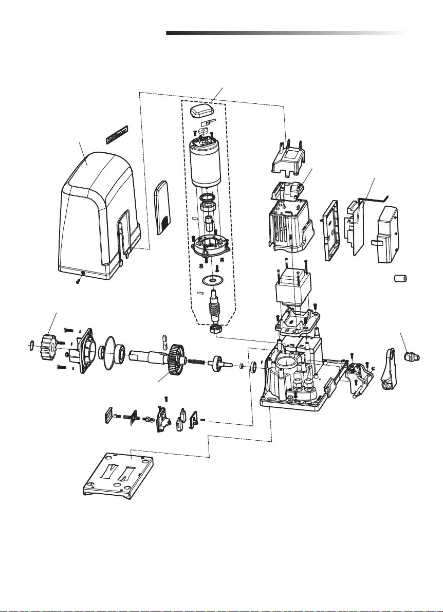
K210720 (Model SL600)
K210794 (Model SL1000)
Operator Cover and
Access Door
K320174
Output Gear
K130026 (Model SL600)
K130046 (Model SL1000)
Motor Assembly
K140368
Power Board
K140364
Control Board
K320440
Replacement Key
and Tumbler
K210504
Worm Gear Plastic
27
Page 28
ACCESSORIES
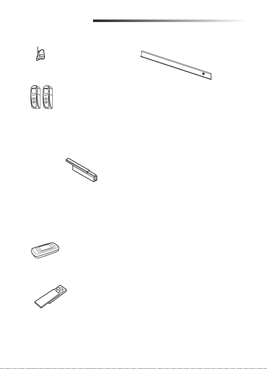
FA31LM Flashing Light
FA42LM Photoelectric Sensor
ME113
ME120
ME123
MU21
MU22
MGO20
MGR20
MGS20
G65ME120C5 Sensing Edge Channel
Sensing Edge (2-wire,
non-monitored, contact)
Sensing edges can detect an
obstacle upon contact and stop
the operator.
Mounting channel for all
MG020 type edges.
202097 Rack
ANTEX12 Antenna
828LM LiftMaster Internet Gateway
TX4UNI Remote Control
For support contact:
28
Page 29
OPERADOR DE PORTONES
RODANTES
MANUAL DE INSTALACIÓN
Modelos SL600 y SL1000
• LEA ATENTAMENTE EL MANUAL ANTES DE PROCEDER
CON LA INSTALACIÓN Y EL USO
• ESTE PRODUCTO DEBE SER INSTALADO POR UN TÉCNICO
PROFESIONAL EN SISTEMAS PARA PORTONES.
Page 30

CONTENIDO
SEGURIDAD
Medidas de seguridad para portones batientes y de reja ornamental ......................................................3
Información importante de seguridad .................................................................................................. 4-5
INTRODUCCIÓN
Especificaciones .......................................................................................................................................6
Contenido de la caja .................................................................................................................................6
Herramientas necesarias ..........................................................................................................................7
Vista general del operador de portón .......................................................................................................7
INSTALACIÓN
Dimensiones del operador .......................................................................................................................8
Preparar e instalar la placa de montaje .............................................................................................. 8-10
Instalación del operador ........................................................................................................................11
Instalación del soporte del límite de carrera ..........................................................................................11
Desacoplar el embrague ........................................................................................................................12
CONEXIONES
Elección de voltaje .................................................................................................................................13
Conexión de alimentación eléctrica ........................................................................................................14
Instalar la protección contra atrapamiento ............................................................................................15
Diagrama de conexiones ........................................................................................................................16
Batería de reserva (opcional) .................................................................................................................17
CALIBRACIÓN DEL LÍMITE DE DESPLAZAMIENTO ...............................................................................18
PROGRAMACIÓN
Control remoto .......................................................................................................................................18
Calibración de apertura parcial ..............................................................................................................18
Borrar todos los códigos .......................................................................................................................19
LiftMaster
Borrar un LiftMaster
CONFIGURACIÓN
Mayor fuerza inicial ................................................................................................................................20
Calibración de apertura parcial ..............................................................................................................20
Cierre automático ...................................................................................................................................20
Calibración de límites de carrera............................................................................................................20
Regulación de la fuerza ..........................................................................................................................21
Parada suave .........................................................................................................................................21
Calibración de la velocidad de movimiento ............................................................................................21
Identificación de apertura y cierre..........................................................................................................21
Luz intermitente (opcional) ....................................................................................................................22
Conexión del sensor fotoeléctrico y el sensor de borde ........................................................................22
USO Y MANTENIMIENTO ................................................................................................................. 23-25
DIAGNÓSTICO DE FALLAS ....................................................................................................................26
PIEZAS DE REPUESTO ..........................................................................................................................27
ACCESORIOS .........................................................................................................................................28
®
Internet Gateway .................................................................................................................19
®
Internet Gateway .................................................................................................19
2
Page 31
ADVERTENCIA
ADVERTENCIA
ADVERTENCIA
PRECAUCIÓN
ADVERTENCIA
ADVERTENCIA
ADVERTENCIA
SEGURIDAD
ADVERTENCIA
ADVERTENCIA
Estas advertencias y/o símbolos de seguridad que
aparecen a lo largo de este manual le alertarán de la
existencia de riesgo de una lesión seria o de muerte si no
se siguen las instrucciones correspondientes. El peligro
puede ser eléctrico (electrocución) o mecánico. Lea
atentamente las advertencias.
Cuando vea esta palabra y/o símbolo de seguridad a lo
largo de este manual le alertará de que existe el riesgo
de dañar el portón y/o el operador del mismo si no
se siguen las instrucciones correspondientes. Léalas
detenidamente.
NOTA IMPORTANTE:
• ANTES de instalar, usar o reparar el operador, debe leer y comprender totalmente este manual y
seguir todas las instrucciones de seguridad.
• Estas instrucciones destacan temas importantes de seguridad. Estas instrucciones no son de
aplicación general para todos los casos. Como cada instalación tiene sus propias características, la
seguridad y aptitud de funcionamiento del portón es responsabilidad del comprador, del técnico de
instalación y del usuario fi nal.
• Conserve estas instrucciones.
Medidas de seguridad para portones batientes y de reja ornamental
ADVERTENCIA
ADVERTENCIA
MECÁNICA
ADVERTENCIA
ELECTRICIDAD
PRECAUCIÓN
Para evitar LESIONES GRAVES o la MUERTE por accidentes con el portón en movimiento:
• INSTALAR dispositivos de protección contra atrapamiento por la seguridad de las personas que
se acerquen a un portón en movimiento.
• Usar dispositivos de seguridad tanto para apertura como para cierre.
• Instalar protección contra atrapamiento para cubrir los espacios entre el portón y objetos
RÍGIDOS, tales como columnas y postes.
• El portón NO debe abrirse hacia lugares de acceso público.
• Este operador NO debe ser usado por personas (incluyendo niños) que tengan capacidad física,
sensorial o mental disminuida, ni por quienes no tengan experiencia ni conocimiento sobre el
uso, a menos que hubieran recibido supervisión o instrucciones sobre el uso del dispositivo por
parte de la persona responsable de su seguridad.
• Vigile a los niños para que NO usen el operador como un juguete.
• CONSERVAR ESTAS INSTRUCCIONES.
3
Page 32

ADVERTENCIA
ADVERTENCIA
SEGURIDAD
INFORMACIÓN IMPORTANTE DE SEGURIDAD
ADVERTENCIA
Para reducir el riesgo de LESIONES GRAVES o la MUERTE por defectos de instalación:
1. Los sistemas de control de paso vehicular son prácticos y seguros. Los sistemas operadores
de portones tienen varios componentes. La unidad operadora es UNO de esos componentes.
Cada sistema está diseñado específicamente para una aplicación individual.
2. Los diseñadores, instaladores y usuarios del sistema de operación DEBEN tener en cuenta los
posibles peligros relacionados con cada aplicación individual. Los sistemas incorrectamente
diseñados, instalados o mantenidos pueden crear riesgos para el usuario y los transeúntes. El
diseño y la instalación de los sistemas abre-puertas DEBEN minimizar los potenciales peligros
para el público.
3. El operador puede crear fuerzas de magnitud como componente del sistema. Por lo tanto, todo
diseño debe incluir funciones de seguridad. Entre estas funciones de seguridad pueden
mencionarse:
• Bordes especiales • Protección de rodillos • Sensores fotoeléctricos
• Mallas • Columnas • Carteles de instrucciones y seguridad
4. Instalar el operador sólo cuando:
a. El operador es apropiado para la construcción y el uso de la puerta.
b. TODAS las aberturas de un portón rodante horizontal estén protegidas o cubiertas por una
malla desde la parte inferior hasta un mínimo de 4 pies (1.2 m) sobre el nivel del suelo para
impedir que una esfera de 2 1/4 de pulg. (6 cm) de diámetro atraviese cualquiera de las
aberturas, y en la parte de la cerca adyacente que el portón cubra en posición abierta.
c. Se hayan eliminado o protegido TODOS los puntos de presión expuestos, y se hayan
colocado protecciones para los rodillos que quedan expuestos.
5. El operador debe usarse únicamente con portones para paso de vehículos. Los peatones deben
ser provistos de una vía de acceso independiente.
6. El portón DEBE instalarse en un lugar de modo que haya suficiente espacio libre entre el
portón y las estructuras adyacentes al abrirse y cerrarse, para reducir el riesgo de quedar
atrapado.
7. Antes de instalar el operador, el portón debe estar instalado y DEBE moverse libremente en
ambas direcciones.
8. Los controles DEBEN estar alejados del portón, a una distancia que impida que el usuario entre
en contacto con el portón cuando usa los controles.
9. ANTES de instalar el accionamiento verificar que las partes movidas por él estén en buenas
condiciones mecánicas, balanceadas y que se abran y cierren normalmente.
4
Page 33

SEGURIDAD
ADVERTENCIA
ADVERTENCIA
INFORMACIÓN IMPORTANTE DE SEGURIDAD
ADVERTENCIA
10. Para un operador de portón con sensor sin contacto:
a. Consultar el manual del instrucciones para determinar el lugar de montaje del sensor para
cada tipo de aplicación.
b. Tomar precauciones para reducir el riesgo de tropiezos cuando un vehículo activa un sensor
cuando el portón todavía está en movimiento.
c. Donde haya riesgo de atrapamiento u obstrucción, tal como el perímetro de movimiento del
portón o la barrera, es necesario instalar uno o más sensores sin contacto.
11. Para un operador con sensor de contacto, tal como un sensor de borde:
a. El montaje y las conexiones del sensor de contacto con el operador deben ubicarse de
manera que haya riesgo de daños accidentales.
b. Un sensor de contacto inalámbrico, como el que transmite señales de frecuencia de radio
(RF) al operador del portón para las funciones de protección de atrapamiento estará ubicados
donde no esté obstruidas la transmisión de las señales. Un sensor de contacto inalámbrico
debe funcionar según las condiciones estipuladas de uso.
c. En un portón deslizante horizontal para acceso de vehículos deben instalarse sensores de
contacto en ambos laterales y del interno y externo de la columna.
d. Del lado interno y externo del borde vertical del portón se instalarán sensores de contacto.
Además, si el borde inferior de un portón está a más de 6 pulg. (15 cm) sobre el nivel del
suelo en cualquier punto de su trayectoria, deben instalarse uno o más sensores de contacto
en dicho borde.
12. En puertas para peatones de movimiento horizontal evitar que queden zonas de atrapamiento
entre las partes en movimiento y las partes fijas que las rodean. Esto podría lograrse dejando
una distancia de NO más de 8 mm entre partes móviles y fijas. No obstante, las siguientes
distancias se consideran suficiente para evitar atrapamiento de las partes indicadas del cuerpo:
a. Dedos: más de 25 mm
b. Pies: más de 50 mm
c. Cabeza: más de 300 mm
d. Cuerpo entero: más de 500 mm
Si no es posible dejar estas distancias, es necesario colocar dispositivos de protección.
IMPORTANTE: En Perú y Chile está prohibido el uso de la tecnología MyQ y accesorios compatibles en
portones.
5
Page 34
INTRODUCCIÓN
Especificaciones
Alimentación principal de CA: 110-127 VCA / 220-240VCA; 50/60 Hz
Voltaje del motor:
Potencia:
100 W
Rango de temperatura ambiente:
Peso máximo del portón:
Ancho máximo del portón:
Fuerza máxima de tracción (N):
Clasifi cación de protección: IP 44
Velocidad de desplazamiento:
Ciclos diarios de funcionamiento: Máximo de 50 ciclos por día
Peso del operador: 6 Kg
Contenido de la caja
24 VCC
-25 ~ +50 ˚C
600 Kg (Modelo SL600)
1000 Kg (Modelo SL1000)
8 m
780 (Modelo SL600)
970 (Modelo SL1000)
22 cm/s
Tornillo expandible M8x80 (4)
Placa de montaje
Tornillo M8 X40 con tuerca
hexagonal y arandela plana
(conjuntos)
Llave de acople (2)
Operador del portón
Manual de
instalación
(no mostrado)
Control remoto, modelo TX4UNI (2)
Soporte del límite de
carrera (2)
6
Page 35
INTRODUCCIÓN
Herramientas necesarias
Vista general del operador de portón
Los cables deben cumplir con todos los códigos locales y nacionales para el uso al aire libre.
Luz intermitente
Sensor
fotoeléctrico
Portón
Operador de
portón
Control
remoto
Soporte del límite
de carrera
Bastidor
7
Page 36
INSTALACIÓN
Dimensiones del operador
294 mm
270 mm
218 mm
Preparar e instalar la placa de montaje
Las instrucciones e ilustraciones en este manual se ofrecen como ejemplo ÚNICAMENTE. Cada
instalación puede variar según el espacio disponible, las obstrucciones y los accesorios utilizados. El
técnico de instalación debe encontrar la mejor solución.
1. Hacer un agujero a un lado del portón (Figura 1). La capa de concreto debe tener mayor espesor
que la profundidad de congelamiento. Consultar los códigos nacionales y municipales vigentes.
Figura 1
3.98 cm
(1.57 pulg.)
30.47 cm
(12 pulg.)
23.97 cm
(9.44 pulg.)
39.97 cm
(15.74 pulg.)
8
Page 37
INSTALACIÓN
2. Abrir un canal e instalar el conducto eléctrico.
El conducto debe ser de 3/4 de pulg. de
diámetro como máximo.
NOTA: La cantidad de conductos dependerá del
lugar de instalación y los accesorios instalados.
3. Preparar un molde de encofrado que sea más
grande que la placa de montaje e introducirlo
en el agujero (Figura 2). El encofrado debería
quedar a 1-3/4 de pulg. (50 mm) sobre el nivel
del suelo (Figura 2).
4. Colocar una rejilla de acero en el encofrado
para reforzar el concreto (Figura 2).
5. Llenar la caja con concreto y esperar a que se
cure durante al menos 24 horas (Figura 3).
Figura 2
Figura 3
1-3/4 de pulg.
(50 mm)
6. Quitar el encofrado (Figura 4).
7. Llenar el agujero alrededor del concreto con
tierra (Figura 4).
Figura 4
9
Page 38
INSTALACIÓN
8. Colocar la placa de montaje en la posición
correspondiente (Figura 5).
Figura 5
Bastidor
VISTA SUPERIOR DEL PORTÓN
Portón
Bastidor
11 cm
Placa de montaje
La distancia entre el
bastidor y el portón
debe ser de 2.4 cm.
3 cm
Placa de montaje
9. Pasar los cables por el orifi cio de salida
(Figura 6).
10. Marcar el lugar de los agujeros de montaje
y hacer los agujeros con una broca para
mampostería. Fijar la placa de montaje con los
accesorios suministrados (Figura 6).
Figura 6
Cables
10
Page 39
INSTALACIÓN
Instalación del operador
Antes de instalar el operador verifi car que el portón se mueva libremente. Tal como se muestra, debe
quedar una separación entre el bastidor y el engranaje para que el movimiento del portón no se vea
afectado.
2-3 mm
Engranaje
Bastidor
110 mm
Nivel de suelo
Soporte del límite
de carrera
Instalación del soporte del límite de carrera
Fijar con los tornillos el soporte del límite de carrera al bastidor. Si el soporte se instala
incorrectamente, el portón no responderá al límite de carrera.
INSTALACIÓN CORRECTA
Soporte del límite
de carrera
Ajustar el soporte del
límite de carrera
INSTALACIÓN INCORRECTA
Operador
Portón
Soporte del límite
de carrera
Resorte del límite
de carrera
Bastidor
Engranaje
Rueda
Placa de montaje
Carril
Bastidor
Tornillo de fijación
11
Page 40
INSTALACIÓN
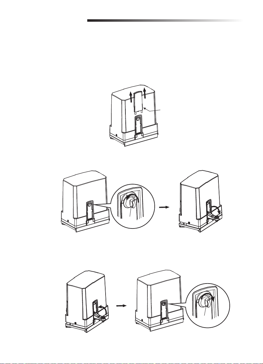
Desacoplar el embrague
Desacoplar el embrague por las siguientes razones:
• Para abrir y cerrar el portón en caso de un corte de energía.
• Para restituir las funciones.
• Mantenimiento del operador.
1. Quitar la tapa de la llave.
Tapa de la llave
2. Para desacoplar el embrague girar la llave y tirar hacia abajo la palanca del mecanismo manual.
Llave de
desbloqueo
Desacoplar
el embrague
3. Para acoplar el embrague llevar la palanca manual a la posición superior (deben quedar alineadas
las pestañas del alojamiento y de la palanca) y girar la llave a la posición de bloqueo.
NOTA: Después de colocar la tapa y fi nalizar los movimientos, recuerde bloquear el embrague.
Bloquear el embrague
Llave de
desbloqueo
12
Page 41
ADVERTENCIA
ADVERTENCIA
CONEXIONES
Para reducir el riesgo de LESIONES GRAVES o la MUERTE:
• No realizar mantenimiento en el operador ni en el área cercana al mismo sin cortar la
alimentación eléctrica (CA, solar y batería). Al terminar el mantenimiento, limpiar y asegurar el
área antes de que el portón vuelva a entrar en servicio.
• Desconectar la alimentación eléctrica en la caja de fusibles ANTES de continuar.
NOTA: La alimentación eléctrica del operador debe originarse en una línea independiente con
fusibles propios.
• Un técnico profesional DEBE realizar la instalación eléctrica.
• NO haga conexiones ni ponga en funcionamiento el operador sin consultar el esquema de
conexiones y cableado.
• La alimentación eléctrica DEBE estar en un circuito independiente y con protección apropiada.
• El cableado de alimentación y de control DEBE estar en conductos separados.
• ANTES de instalar el cableado el alimentación y control verificar que se cumplan las
especificaciones e instrucciones siguientes. Esto es para evitar GRAVES ACCIDENTES LESIVOS y
daños materiales.
Elección de voltaje
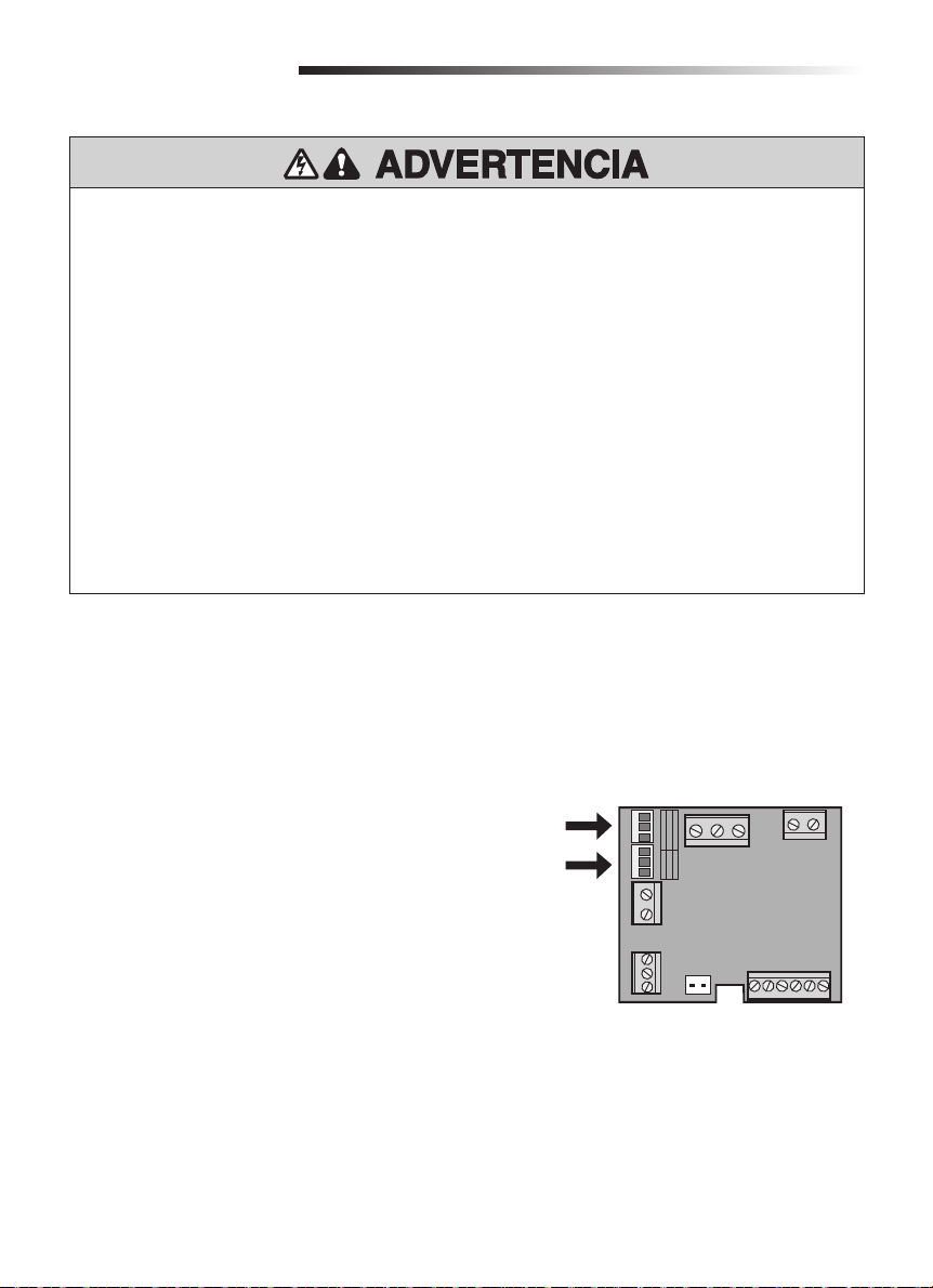
El operador puede utilizarse con 110-127 VCA o 220-240 VCA cambiando la posición de un puente.
NOTA: El puente viene de fábrica para alimentación en 220 VCA.
Para alimentación en 110-127 VCA:
1. Cortar la alimentación eléctrica con el
interruptor principal del circuito.
2. Colocar el puente en J3 y la tapa en J2 en la
tarjeta de alimentación.
TARJETA DE ALIMENTACIÓN
J2
J3
110-127Vac 220-240Vac
J3 J2
OFF
NL
POWER LINE
ON
OFF
ON
CN6
J3
J2
N
127V
230V
CN3
TR IN
CN1
Para alimentación en 220-240 VCA:
1. Cortar la alimentación eléctrica con el
interruptor principal del circuito.
PE
CN2
BAT
CHCTR VBAT
CN7
2. Colocar el puente en J2 y la tapa en J3 en la
tarjeta de alimentación.
13
TR OUT
CN4
+
DC
Page 42
CONEXIONES
ADVERTENCIA
ADVERTENCIA
Para reducir el riesgo de LESIONES GRAVES o la MUERTE:
• NO TOQUE las conexiones no utilizadas en J2 o J3, ya que están energizados.
• Colocar la tapa antes de conectar o volver a conectar la alimentación eléctrica.
Conexión de alimentación eléctrica
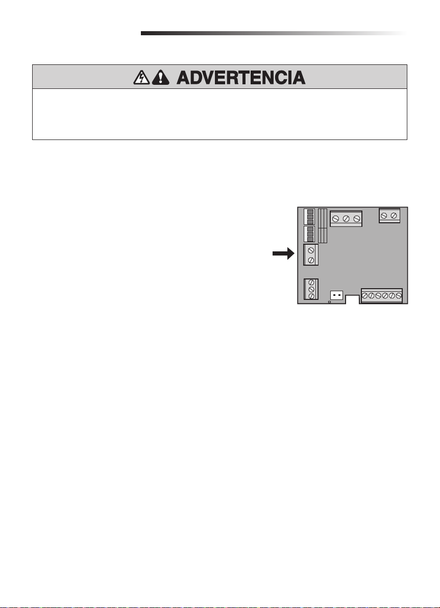
El operador puede conectarse a 110-127 VCA o 220-240 VCA.
1. Cortar la alimentación eléctrica con el
interruptor principal del circuito.
2. Pasar los conductores de CA por la entrada
más cercana al motor.
3. Conectar la fase de alimentación al terminal L
de la tarjeta.
4. Conectar el neutro al terminal N de la tarjeta.
5. Ajustar bien la tuerca del conector pasante.
6. Conectar la alimentación eléctrica del
operador.
Alimentación
eléctrica
TARJETA DE ALIMENTACIÓN
J3 J2
NL
POWER LINE
PE
CN7
N
127V
230V
J2
J3
110-127Vac 220-240Vac
OFF
ON
OFF
ON
CN6
CN2
CHCTR VBAT
CN3
TR IN
CN1
BAT
TR OUT
CN4
+
DC
14
Page 43
CONEXIONES
PRECAUCIÓN
ADVERTENCIA
ADVERTENCIA
ADVERTENCIA
Para evitar LESIONES GRAVES o la MUERTE por accidentes con el portón en movimiento:
• INSTALAR dispositivos de protección contra atrapamiento por la seguridad de las personas que
se acerquen a un portón en movimiento.
• Usar dispositivos de seguridad tanto para apertura como para cierre.
• Instalar protección contra atrapamiento para cubrir los espacios entre el portón y objetos
RÍGIDOS, tales como columnas y paredes.
Instalar los dispositivos de protección contra atrapamiento
Ver en la página de Accesorios la lista completa de dispositivos de seguridad aprobados.
Funcionalidad con IR1
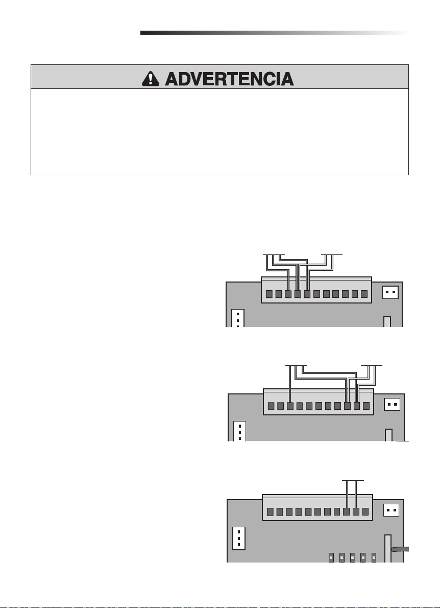
SENSORES FOTOELÉCTRICOS
El funcionamiento del sensor fotoeléctrico
dependerá de que esté conectado a la entrada IR1 o
IR2. Ver la explicación de su funcionamiento en la
sección de confi guración en la página 22.
1. Quitar el puente que viene de fábrica en la
entrada IR1 o IR2.
2. Conectar el receptor del sensor fotoeléctrico a
IR1 y a tierra (GND) o a IR2 y a tierra (GND),
según la funcionalidad asignada.
3. Conectar el transmisor del sensor fotoeléctrico
a IR+24V, IR1 y tierra (GND) o a IR+24V, IR2 y
tierra (GND).
Transmisor del sensor
fotoeléctrico
CN3
DCLAMP
+24V
Transmisor del sensor
fotoeléctrico
TARJETA DE CONTROL
Receptor del sensor
fotoeléctrico
GND
IR+24V
IR1
Funcionalidad con IR2
SW1
SW2
TARJETA DE CONTROL
IR2
GND
Receptor del sensor
fotoeléctrico
CN2
STOP
SENSOR DE BORDE
El sensor de borde debe conectarse únicamente
a IR2.
1. Quitar el puente que viene de fábrica entre IR2
y tierra (GND).
2. Conectar el sensor de borde a IR2 y tierra
(GND).
CN3
TARJETA DE CONTROL
CN3
CN4
15
+24V
+24V
DCLAMP
DCLAMP
IR+24V
IR+24V
IR1
IR1
GND
SW1
Sensor de borde
GND
SW1
LED1
SW2
SW2
IR2
LED2
CN2
STOP
IR2
GND
CN2
STOP
GND
LED3
LED4
LED5
Page 44
CONEXIONES
ALIMENTACIÓN
ELÉCTRICA
TARJETA DE
ALIMENTACIÓN
J2
J3
110-127Vac 220-240Vac
J3 J2
OFF
ON
OFF
ON
NL
POWER LINE
CN6
PE
CN7
Luz intermitente
de CC
CN3
230V
CN2
CHCTR VBAT
Batería de reserva
fotoeléctrico
DCLAMP
+24V
Transformador
(entrada)
127V
N
CN3
TR IN
CN1
BAT
Sensor fotoeléctrico o borde
Límite de carrera
Sensor
IR+24V
GND
IR1
SW1
SW2
IR2
Transformador
(salida)
TR OUT
CN4
+
DC
CN2
STOP
GND
Interruptor de parada
de emergencia
TARJETA DE CONTROL
Operador
M1M2
Operador
CN4
LED1
LED2
LED3
LED4
LED5
CN1
RF
Antena
MOTOR DC
Control de un
solo botón es
un mando de
RV
FORCE
LEARN
S2
LV
ON
12345678
SBC
S1
ON
apertura/cierre
para una sola
portón.
16
Page 45
CONEXIONES
Batería de reserva (opcional)
Las baterías se cargan a través del circuito con el transformador. Elementos recomendados para uso
con una batería de reserva (no suministrados):
• Dos baterías de 12 V, 4 A-H (McNair Modelo RB-FM-12V-4AH)
• Caja de batería (Attwood Modelo 9069-1)
• 3 x 18 AWG (1.00 mm) VM-1 105˚C 600 V, 1 cable debe tener fusible de 10 A/250 V
1. Desconectar la alimentación eléctrica al operador.
2. Pasar los cables de alimentación desde la batería por la misma entrada que los cables de
alimentación de CA.
3. Conectar el cable de la batería a los terminales marcados como BATTERY en la tarjeta de
alimentación.
4. Instalar la caja de la batería (a no más de 10 pies de distancia del operador).
5. Colocar las baterías en la caja.
6. Conectar un puente con fusible entre el positivo (+) de una batería y el negativo (-) de la otra.
7. Conectar el cable del positivo de batería al terminal positivo (+) de la batería.
8. Conectar el cable del negativo de batería al terminal negativo (-) de la otra batería.
9. Conectar la alimentación eléctrica al operador.
10. Colocar la tapa del operador.
230V
J2
J3
J3 J2
NL
POWER LINE
PE
110-127Vac 220-240Vac
OFF
ON
OFF
ON
CN6
CN2
CHCTR VBAT
CN7
TARJETA DE ALIMENTACIÓN
N
127V
TR IN
CN1
+-
BAT
CN3
TR OUT
Puente con
fusible de
10 A/250 V
(no incluido)
CN4
+
DC
17
Page 46
CALIBRACIÓN DE LÍMITES
DE DESPLAZAMIENTO
Los límites de carrera pueden calibrarse con el portón cerrado o abierto.
SBC
1. Mantener pulsado el botón
durante 5 segundos. El DL5 parpadeará.
2. Pulsar el control remoto o el botón
SBC
.
3. El portón se abrirá o cerrará, y se detendrá cuando el soporte del límite del carrera llegue al resorte
del relé. El operador guardará en memoria esta calibración.
Al calibrar los límites de desplazamiento, el operador debe moverse primero en la dirección de cierre. Si
el portón se desplaza en la dirección de apertura, cambiar la posición del microselector 5.
NOTA: El operador del portón cancelará el modo de programación después de 30 segundos de
inactividad.
PROGRAMACIÓN
Control Remoto
1. Oprimir y soltar el botón
2. Pulsar el botón del control remoto que desea programar.
El operador saldrá automáticamente del modo de aprendizaje cuando haya fi nalizado la programación
(el LED1 parpadeará y se apagará). Para programar otros controles remotos Security+ 2.0™ repetir los
pasos anterior de programación. Pulsar otra vez el botón LEARN (aprendizaje) para salir del modo de
programación en cualquier momento.
Calibración de apertura parcial
1. Oprimir y soltar el botón
2. Oprimir y soltar el botón
3. Pulsar el botón del control remoto que se programará para calibrar la apertura parcial (debe ser un
botón diferente al de comando normal del portón).
LEARN
(se encenderá el LED1).
LEARN
. El LED1 de encenderá.
LEARN
nuevamente. El LED1 comenzará a parpadear.
NOTIFICACIÓN: El uso está sujeto a las siguientes condiciones: (1) Este dispositivo no debe causar interferencia perjudicial, y (2) este dispositivo debe
poder recibir interferencia, incluso interferencia que pueda afectar su funcionamiento.
Cualquier cambio o modifi cación no aprobados explícitamente por la parte responsable del cumplimiento, podría anular la autoridad del usurario para
operar el equipo.
Este dispositivo está diseñado para proporcionar una protección razonable contra las interferencias dañinas en una instalación residencial.Este
equipo genera, usa y puede emitir energía de radiofrecuencia. Si no se instala y utiliza de acuerdo con las instrucciones podrá causar interferencia
con comunicaciones radiales. Aun así, no hay garantía de que no se produzcan interferencias en una instalación particular. Si este equipo produce
interferencia en la recepción de radio o televisión, lo cual puede determinarse apagando y encendiendo la unidad, el usuario debe tratar de corregir el
problema por medio de lo siguiente:
- Reorientar o reubicar la antena de recepción.
- Conectar el equipo a un tomacorriente de un circuito eléctrico diferente al que esté conectado el receptor.
- Consultar al distribuidor del producto o a un técnico idóneo de radio y televisión.
18
Page 47

PROGRAMACIÓN
Borrar todos los códigos
1. Mantener oprimido el botón
2. Mantenerlo oprimido durante aproximadamente 8 segundos. El LED1 se apagará y se borrarán los
códigos del control remoto.
LiftMaster® Internet Gateway
IMPORTANTE: En Perú y Chile está prohibido el uso de la tecnología MyQ y accesorios compatibles en
portones.
Para programar el operador con el LiftMaster
1. Conectar el cable de Ethernet al LiftMaster
2. Conectar la alimentación eléctrica al LiftMaster
3. Crear una cuenta por Internet en el sitio www.myliftmaster.com.
®
4. Registrar el LiftMaster
Internet Gateway.
5. Agregue dispositivos con una computadora o un teléfono inteligente vía Internet. El LiftMaster
Internet Gateway permanecerá en modo de aprendizaje durante tres minutos.
6. Pulse el botón LEARN (aprendizaje) en el operador (el LED1 se encenderá en modo de aprendizaje).
El LiftMaster
®
Internet Gateway se conectará al operador si la distancia es adecuada, y el LED1
parpadeará y se apagará si la programación se hubiera realizado.
Borrar un LiftMaster® Internet Gateway
LEARN
®
(se encenderá el LED2).
Internet Gateway:
®
Internet Gateway y al router.
®
Internet Gateway.
®
1. Mantener oprimido el botón
LEARN
(se encenderá el LED1).
2. Mantenerlo oprimido durante aproximadamente 8 segundos. El LED1 se apagará y se borrarán los
códigos del control remoto.
3. Mantener oprimido el botón LEARN (aprendizaje) por segunda vez (se encenderá otra vez el LED1).
4. Mantenerlo oprimido durante aproximadamente 8 segundos. El LED1 se apagará y se borrarán los
códigos Gateway.
19
Page 48
CONFIGURACIÓN
Mayor fuerza inicial
El operador arrancará aplicando una fuerza mayor
que la normal para mover el portón, durante los
primeros 2 segundos (+/-1).
1 ON = Mayor fuerza inicial
1 OFF = Fuerza normal de arranque
Calibración de apertura parcial
Con apertura parcial activada, el portón se abrirá 1
metro. En la sección de Programación se dan las
instrucciones para programar el control remoto
para este modo de apertura.
2 ON = Apertura parcial activada
2 OFF = Apertura parcial desactivada
Cierre automático
Para calibrar la duración del cierre entre 0 y
105 segundos, se suman los valores de cada
microselector llevado a la posición ON (Sí). Valor
de cada microselector:
6 ON = 15 segundos
7 ON = 30 segundos
8 ON = 60 segundos
1 2 3 4 5 6 7 8
ON
S1
OFF
Mayor fuerzainicial activada
1 2 3 4 5 6 7 8
ON
S1
OFF
Apertura parcial activada
1 2 3 4 5 6 7 8
ON
S1
OFF
30 segundos
Calibración de límites de carrera
Posición de fábrica: OFF (normalmente abierto).
4 ON = Límite de carrera con contacto
normalmente cerrado.
4 OFF = Límite de carrera con contacto
normalmente abierto.
1 2 3 4 5 6 7 8
ON
S1
OFF
Normalmente abierto
20
Page 49
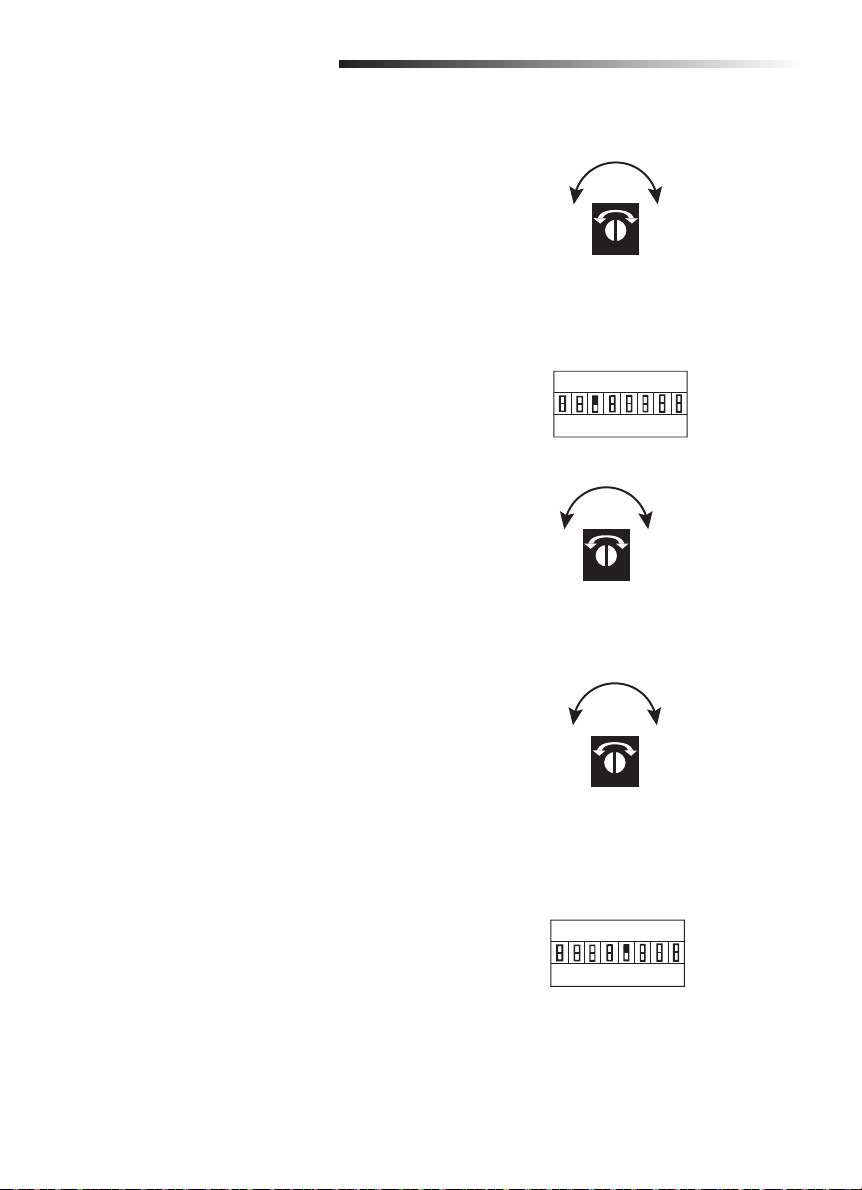
CONFIGURACIÓN
Regulación de la fuerza
El portón se detendrá cuando encuentre un
obstáculo al abrirse, y comenzará a abrirse si
se estuviera cerrando. Si la fuerza calibrada es
muy baja, el portón no funcionará normalmente.
Si la fuerza calibrada es muy alta podría causar
accidentes personales o daños materiales.
Girar el botón FORCE en sentido horario para
incrementar la fuerza del portón. Girar el botón
FORCE en sentido antihorario para reducir la fuerza
del portón.
Parada suave
Con la función de parada suave, el portón se
detendrá suavemente cuando esté llegando al límite
de apertura o de cierre.
3 ON = La parada suave dura 3 segundos
3 OFF = La parada suave dura 4 segundos
Girar el botón LV en sentido horario para aumentar
la duración de la parada suave. Girar el botón LV en
sentido antihorario para reducir la duración de la
parada suave.
IncrementarReducir
FORCE
1 2 3 4 5 6 7 8
ON
S1
OFF
Función de parada suave activada
IncrementarReducir
LV
Calibración de la velocidad de
movimiento
Girar el botón RV en sentido horario para aumentar
la velocidad del portón en movimiento. Girar el
botón RV en sentido antihorario para disminuir la
velocidad del portón en movimiento.
Identificación de apertura y cierre
Si el portón reacciona incorrectamente ante un
obstáculo, llevar el microselector 5 a la posición
opuesta para corregir el problema.
Correcto: Si el portón se está cerrando y se
interrumpe el haz del sensor fotoeléctrico o el
portón encuentra un obstáculo, el portón invierte su
dirección inmediatamente y se abre.
Incorrecto: Si el portón se está cerrando y se
interrumpe el haz del sensor fotoeléctrico o el
portón encuentra un obstáculo, el portón se detiene
o continúa cerrándose.
IncrementarReducir
RV
1 2 3 4 5 6 7 8
ON
S1
OFF
21
Page 50

CONFIGURACIÓN
Luz intermitente (opcional)
Los conectores DCL y GND en la tarjeta corresponden a la luz intermitente FA42LM. La luz intermitente
se encenderá antes de que el portón se abra.
Conexión del sensor fotoeléctrico y el sensor de borde
El contacto del sensor fotoeléctrico y sensor de borde es normalmente cerrado.
SENSOR FOTOELÉCTRICO
Los sensores fotoeléctricos pueden conectarse a IR1 o IR2.
Cuando el haz de un sensor conectado a IR1 se interrumpe, el portón se detendrá e invertirá su
dirección si se estuviera cerrando, o se detendrá si se estuviera abriendo. El LED IR1 en la tarjeta de
control se apagará. Cuando el haz de un sensor conectado a IR2 se interrumpe, el portón se detendrá e
invertirá su dirección durante 1 segundo si se estuviera cerrando, o se detendrá si se estuviera abriendo.
El LED IR2 en la tarjeta de control se apagará.
SENSOR DE BORDE
Los sensores de borde pueden conectarse únicamente a IR2.
Cuando sensor de borde conectado a IR2 hace contacto, el portón se detendrá e invertirá su dirección
durante 1 segundo si se estuviera cerrando, o se detendrá si se estuviera abriendo. El LED IR2 en la
tarjeta de control se apagará.
22
Page 51

USO Y MANTENIMIENTO
PRECAUCIÓN
ADVERTENCIA
ADVERTENCIA
ADVERTENCIA
Instrucciones importantes de seguridad
• LEA Y CUMPLA TODAS LAS INSTRUCCIONES.
• NO permita que los niños usen ni jueguen con los controles de un portón. Mantenga el control
remoto alejado de los niños.
• Mantenga SIEMPRE a la gente y los objetos alejados del portón. NADIE DEBE ATRAVESAR EL
RECORRIDO DEL PORTÓN EN MOVIMIENTO.
• Probar el funcionamiento del operador del portón una vez por mes. El portón DEBE invertir su
dirección al entrar en contacto con un objeto rígido o detenerse cuando se activan los sensores
sin contacto. Probar el sistema después de regular la fuerza o el límite de desplazamiento del
operador. Si el operador de portón no se regula correctamente ni se prueba, habrá más riesgo de
accidentes con GRAVES LESIONES e INCLUSO FATALES.
• Usar el desacople de emergencia ÚNICAMENTE si el portón no está en movimiento.
• MANTENGA EL PORTÓN EN BUENAS CONDICIONES DE USO. Consultar el manual de
instrucciones. Use los servicios de un técnico profesional para reparar el portón.
• La entrada / salida está adaptado para vehículos. Los peatones deben ser provistos de una vía de
acceso independiente.
• Haga funcionar el portón SOLAMENTE si lo puede ver claramente, si está correctamente
calibrado y si no hay ninguna obstrucción en su recorrido.
• Usar dispositivos de seguridad tanto para apertura como para cierre.
• Este operador NO debe ser usado por personas (incluyendo niños) que tengan capacidad física,
sensorial o mental disminuida, ni por quienes no tengan experiencia ni conocimiento sobre el
uso, a menos que hubieran recibido supervisión o instrucciones sobre el uso del dispositivo por
parte de la persona responsable de su seguridad.
• Vigile a los niños para que NO usen el operador como un juguete.
• CONSERVAR ESTAS INSTRUCCIONES.
23
Page 52
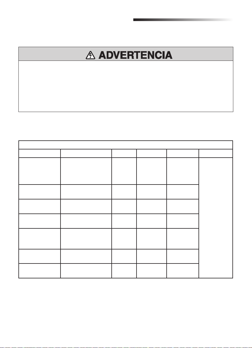
USO Y MANTENIMIENTO
ADVERTENCIA
ADVERTENCIA
Mantenimiento
Para reducir el riesgo de LESIONES GRAVES o la MUERTE:
• Desconectar la alimentación eléctrica ANTES de hacer mantenimiento.
• El mantenimiento DEBE ser realizado por un técnico profesional de LiftMaster
• Usar SIEMPRE guantes y gafas de seguridad para trabajar con la batería.
• Si el cordón de alimentación eléctrica estuviera dañado, por razones de seguridad DEBE ser
cambiado por el fabricante, un representante de servicio o un profesional.
Cuadro de mantenimiento
INSPECCIONAR AL MENOS UNA VEZ CADA
DESCRIPCIÓN TAREA MES 3 MESES 6 MESES 12 MESES
Sistemas de
protección contra
atrapamiento
externo
Letreros de
seguridad
Liberación
manual
Portón Verifi car que no haya
Accesorios Probar el
Instalación
eléctrica
Unidad completa Verifi car que no haya
Probar el
funcionamiento
Verifi car que no falte
ninguno
Probar el
funcionamiento
desgaste ni averías
funcionamiento de
todos
Inspeccionar todas
las conexiones
desgaste ni averías
•
•
•
®
.
Inspección completa
•
•
•
•
24
Page 53
USO Y MANTENIMIENTO
ADVERTENCIA
ADVERTENCIA
Reciclaje
Las baterías de plomo-ácido y ciertos materiales de electrónica son materiales perjudiciales.
Para evitar la contaminación ambiental deben desecharse y reciclarse según las normas vigentes
locales.
Un operador de portón tiene diferentes materiales. Algunos de ellos pueden reciclarse, tales como
aluminio, hierro, plástico, cables, etc., pero no todos son reciclables.
1. Desconectar la alimentación eléctrica del operador.
2. Desarmar el equipo y los accesorios.
3. Quitar la batería de reserva en la caja de control y la batería del control remoto.
4. Desmontar la caja de control.
5. Entregar los materiales reciclables a una compañía local de desecho.
6. La batería de reserva y del control remoto, la caja de control, etc. deben entregarse a una compañía
de reciclaje para evitar la contaminación ambiental.
25
Page 54

DIAGNÓSTICO DE FALLAS
Problema Causa Solución
El operador no funciona
con el control remoto.
El portón no se detiene
en apertura ni en cierre
al tocar el límite de
carrera.
1. El enchufe no está bien
conectado.
2. El embrague está
desacoplado.
3. Falla del sensor fotoeléctrico
o del sensor de borde.
4. Fusible quemado.
5. El código del control remoto
se ha borrado.
6. La batería del control
remoto está descargada.
1. La conexión de los
terminales SW1 y SW2 está
invertida.
2. La conexión de los cables
del motor está invertida.
1. Pedir a un técnico profesional que
conecte la alimentación eléctrica.
2. Acoplar el embrague con la llave
correspondiente.
3. Inspeccionar los sensores
fotoeléctricos y los sensores de
borde. Cambiar los sensores
fotoeléctricos o los sensores de borde
que estuvieran fallados o dañados.
Si no hubieran sensores instalados,
conectar el terminal GND y el terminal
IR con un puente.
4. Cambiar el fusible.
5. Volver a programar el control remoto.
6. Cambiar la batería del control remoto
1. Invertir la conexión de los terminales
SW1 y SW2.
2. Invertir la conexión de los cables del
motor.
El portón no invierte su
dirección al encontrar
un obstáculo.
El portón se abre
automáticamente
durante el cierre.
El portón se abre
automáticamente
cuando está totalmente
cerrado.
El portón no se abre
totalmente.
1. La dirección de cierre del
portón fue programada
incorrectamente.
2. La calibración de fuerza es
muy alta.
La calibración de fuerza es
muy baja.
La dirección de cierre del
portón se ha invertido y la
función automática del portón
de cierre está activo.
El usuario controla el portón
por el botón parcial abierta por
error.
26
1. Llevar el microselector 5 a la posición
opuesta.
2. Girar el selector de fuerza en sentido
antihorario para regular correctamente
la fuerza.
Girar el selector de fuerza en sentido
horario para regular correctamente la
fuerza.
Llevar el microselector 5 a la posición
opuesta.
Controlar el portón con el botón de
apertura y cierre.
Page 55
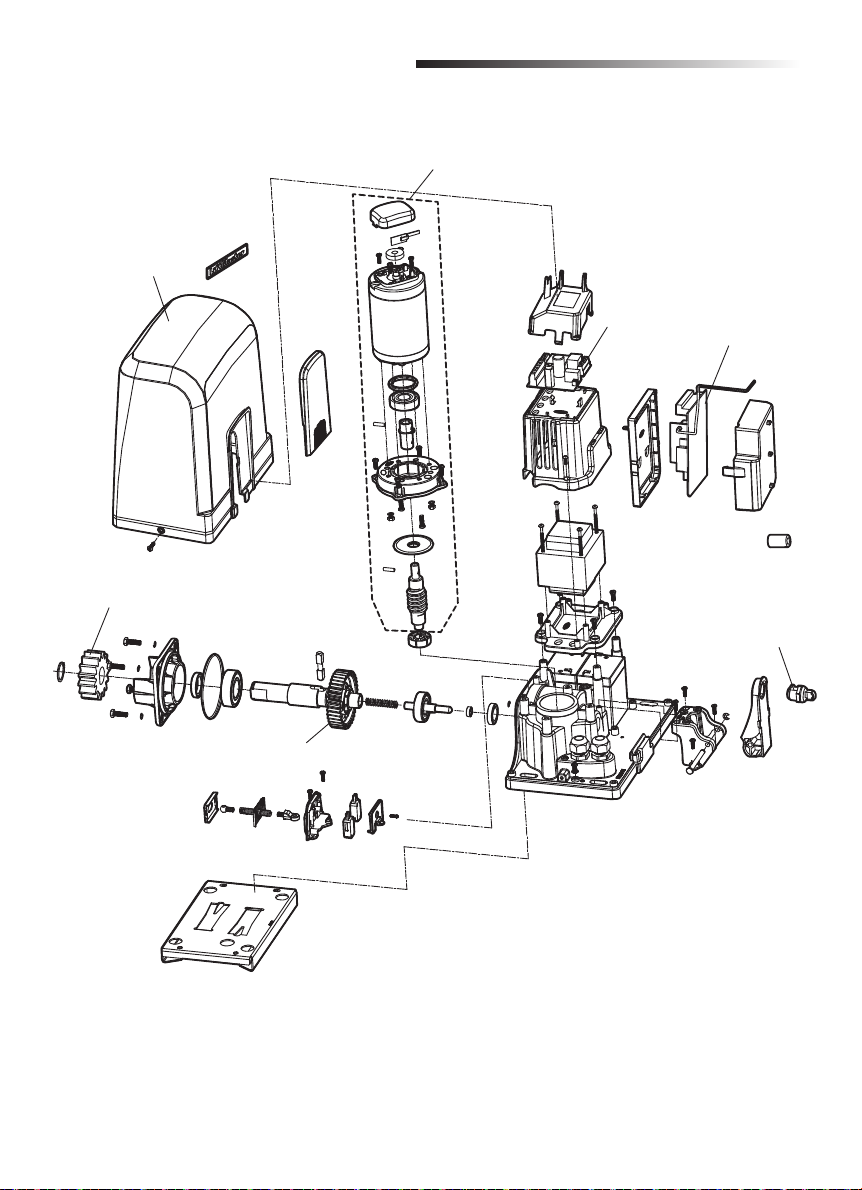
PIEZAS DE REPUESTO
K210720 (Modelo SL600)
K210794 (Modelo SL1000)
Cubierta del operador y
puerta de acceso
K320174
Engranaje de salida
K130026 (Modelo SL600)
K130046 (Modelo SL1000)
Motor completo
K140368
Tarjeta de
alimentación
K140364
Tarjeta de control
K320440
Llave y tambor
de repuesto
K210504
Plástico de la transmisión
de tornillo sin fi n
27
Page 56
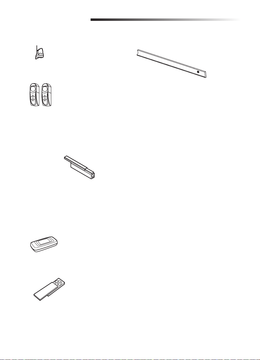
ACCESORIOS
FA31LM Luz intermitente
FA42LM Sensor fotoeléctrico
ME113
ME120
ME123
MU21
MU22
MGO20
MGR20
MGS20
G65ME120C5 Canal del sensor de borde
Sensor de borde (contacto no
monitoreado, 2 conductores)
Los sensores de borde pueden
detectar un obstáculo por
contacto y detener el operador
del portón.
Canal de montaje para los
bordes tipo MG020.
202097 Bastidor
ANTEX12 Antena
828LM LiftMaster Internet Gateway
TX4UNI Control Remoto
Apoyo técnico:
© 2014, LiftMaster
All Rights Reserved
01-37184B Todos los Derechos Reservados
 Loading...