

Page 1
Page 2

Page 3
Page 4
Page 5
Page 6

SPECIFICATIONS AND WARNINGS
SAFETY INSTALLATION INFORMATION
1. Vehicular gate systems provide convenience and security. Gate systems are comprised of many component parts. The gate
operator is only one component. Each gate system is specifically designed for an individual application.
2. Gate operating system designers, installers and users must take into account the possible hazards associated with each individual
application. Improperly designed, installed or maintained systems can create risks for the user as well as the bystander. Gate
systems design and installation must reduce public exposure to potential hazards.
3.
A gate operator can create high levels of force in its function as a component part of a gate system. Therefore, safety features
must be incorporated into every design. Specific safety features include:
• Gate Edges • Guards for Exposed Rollers • Photoelectric Sensors
• Screen Mesh • Vertical Posts • Instructional and Precautionary Signage
4. Install the gate operator only when:
a. The operator is appropriate for the construction and the usage class of the gate.
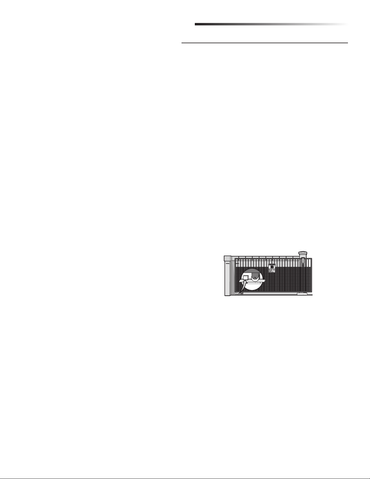
b. All openings of a horizontal slide gate are guarded or screened from the bottom of the gate to a minimum of 4' (1.2 m) above
the ground to prevent a 2-1/4" (6 cm) diameter sphere from passing through the openings anywhere in the gate, and in that
portion of the adjacent fence that the gate covers in the open position.
c. All exposed pinch points are eliminated or guarded, and guarding is supplied for exposed rollers.
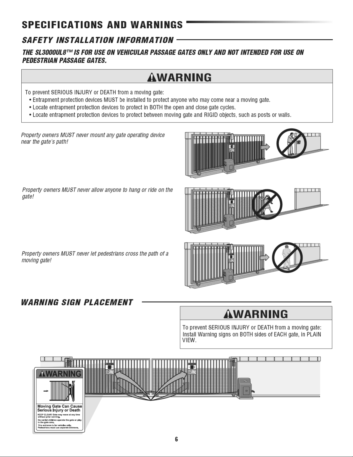
5. The operator is intended for installation only on gates used for vehicles. Pedestrians must be supplied with a separate access
opening. The pedestrian access opening shall be designed to promote pedestrian usage. Locate the gate such that persons will not
come in contact with the vehicular gate during the entire path of travel of the vehicular gate.
6. The gate must be installed in a location so that enough clearance is supplied between the gate and adjacent structures when
opening and closing to reduce the risk of entrapment. Swinging gates shall not open into public access areas.
7. The gate must be properly installed and work freely in both directions prior to the installation of the gate operator.
8. Controls intended for user activation must be located at least six feet (6') away from any moving part of the gate and where the
user is prevented from reaching over, under, around or through the gate to operate the controls. Outdoor or easily accessible
controls shall have a security feature to prevent unauthorized use.
9. The Stop and/or Reset (if provided separately) must be located in the line-of-sight of the gate. Activation of the reset control shall
not cause the operator to start.
10. A minimum of two (2) WARNING SIGNS shall be installed, one on each side of the gate where easily visible.
11. For a gate operator utilizing a non-contact sensor:
a. Reference owner’s manual regarding placement of non-contact sensor for each type of application.
b. Care shall be exercised to reduce the risk of nuisance tripping, such as when a vehicle trips the sensor while the gate is still
moving.
c. One or more non-contact sensors shall be located where the risk of entrapment or obstruction exists, such as the perimeter
reachable by a moving gate or barrier.
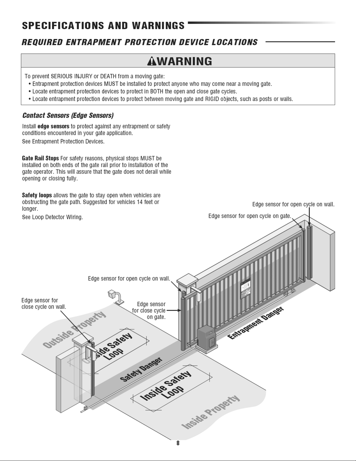
12. For a gate operator utilizing a contact sensor such as an edge sensor:
a. One or more contact sensors shall be located where the risk of entrapment or obstruction exists, such as at the leading edge,
trailing edge and post mounted both inside and outside of a vehicular horizontal slide gate.
b. One or more contact sensors shall be located at the bottom edge of a vehicular vertical lift gate.
c. A hard wired contact sensor shall be located and its wiring arranged so the communication between the sensor and the gate
operator is not subject to mechanical damage.
d. A wireless contact sensor such as the one that transmits radio frequency (RF) signals to the gate operator for entrapment
protection functions shall be located where the transmission of the signals are not obstructed or impeded by building structures,
natural landscaping or similar obstruction. A wireless contact sensor shall function under the intended end-use conditions.
e. One or more contact sensors shall be located on the inside and outside leading edge of a swing gate. Additionally, if the bottom
edge of a swing gate is greater than 6" (152 mm) above the ground at any point in its arc of travel, one or more contact sensors
shall be located on the bottom edge.
f. One or more contact sensors shall be located at the bottom edge of a vertical barrier (arm).
4
Page 7
SPECIFICATIONS AND WARNINGS
GATE CONSTRUCTION INFORMATION
Vehicular gates should be installed in accordance with ASTM F2200: Standard Specification for Automated Vehicular Gate Construction.
For a copy, contact ASTM directly at 610-832-9585 or www.astm.org.
1. General Requirements
1.1 Gates shall be constructed in accordance with the provisions
given for the appropriate gate type listed, refer to ASTM
F2200 for additional gate types.
1.2 Gates shall be designed, constructed and installed to not fall
over more than 45 degrees from the vertical plane, when a
gate is detached from the supporting hardware.
1.3 Gates shall have smooth bottom edges, with vertical bottom
edged protrusions not exceeding 0.50 inches (12.7 mm)
when other than the exceptions listed in ASTM F2200.
1.4 The minimum height for barbed tape shall not be less than 8
feet (2.44 m) above grade and for barbed wire shall not be
less than 6 feet (1.83 m) above grade.
1.5 An existing gate latch shall be disabled when a manually
operated gate is retrofitted with a powered gate operator.
1.6 A gate latch shall not be installed on an automatically
operated gate.
1.7 Protrusions shall not be permitted on any gate, refer to ASTM
F2200 for Exceptions.
1.8 Gates shall be designed, constructed and installed such that
their movement shall not be initiated by gravity when an
automatic operator is disconnected.
1.9 A pedestrian gate shall not be incorporated into a vehicular
gate panel or that portion of the adjacent fence that the gate
covers in the open position.
3.1.3 A gap, measured in the horizontal plane parallel to the
roadway, between a fixed stationary object nearest the
roadway, (such as a gate support post) and the gate frame
when the gate is in either the fully open position or the fully
closed position, shall not exceed 2-1/4 inches (57 mm),
refer to ASTM F2200 for Exception.
3.1.4 Positive stops shall be required to limit travel to the
designed fully open and fully closed positions. These stops
shall be installed at either the top of the gate, or at the
bottom of the gate where such stops shall horizontally or
vertically project no more than is required to perform their
intended function.
3.1.5 All gates shall be designed with sufficient lateral stability to
assure that the gate will enter a receiver guide, refer to
ASTM F2200 for panel types.
3.2 The following provisions shall apply to Class IV vehicular
horizontal slide gates:
3.2.1 All weight bearing exposed rollers 8 feet (2.44 m), or less,
above grade shall be guarded or covered.
3.2.2 Positive stops shall be required to limit travel to the
designed fully open and fully closed positions. These stops
shall be installed at either the top of the gate, or at the
bottom of the gate where such stops shall horizontally or
vertically project no more than is required to perform their
intended function.
2. Specific Applications
2.1 Any non-automated gate that is to be automated shall be
upgraded to conform to the provisions of this specification.
2.2 This specification shall not apply to gates generally used for
pedestrian access and to vehicular gates not to be automated.
2.3 Any existing automated gate, when the operator requires
replacement, shall be upgraded to conform to the provisions
of this specification in effect at that time.
3. Vehicular Horizontal Slide Gates
3.1 The following provisions shall apply to Class I, Class II and
Class III vehicular horizontal slide gates:
3.1.1 All weight bearing exposed rollers 8 feet (2.44 m), or less,
above grade shall be guarded or covered.
3.1.2 All openings located between 48 inches (1.22 m) and 72
inches (1.83 m) above grade shall be designed, guarded or
screened to prevent a 4 inch (102 mm) diameter sphere from
passing through the openings anywhere in the gate, and in
that portion of the adjacent fence that covers in the open
position.
4. Vehicular Horizontal Swing Gates
4.1 The following provisions shall apply to Class I, Class II
and Class III vehicular horizontal swing gates:
4.1.1 Gates shall be designed, constructed and installed so as
not to create an entrapment area between the gate and
the supporting structure or other fixed object when the
gate moves toward the fully open position, subject to the
provisions in the 4.1.1.1 and 4.1.1.2.
4.1.1.1 The width of an object (such as a wall, pillar or column)
covered by a swing gate when in the open position shall
not exceed 4 inches (102 mm), measured from the
center line of the pivot point of the gate, refer to ASTM
F2200 for exception.
4.1.1.2 Except for the zone specified in Section 4.1.1.1, the
distance between a fixed object such as a wall, pillar or
column, and a swing gate when in the open position
shall not be less than 16 inches (406 mm), refer to
ASTM F2200 for exception.
4.2 Class IV vehicular horizontal swing gates shall be
designed, constructed and installed in accordance with
security related parameters specific to the application in
5
question.
Page 8
Page 9
Safety Danger
for CLOSE Cycle
SPECIFICATIONS AND WARNINGS
REQUIRED ENTRAPMENT PROTECTION DEVICE LOCATIONS
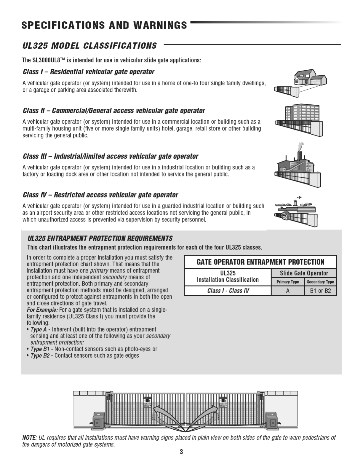
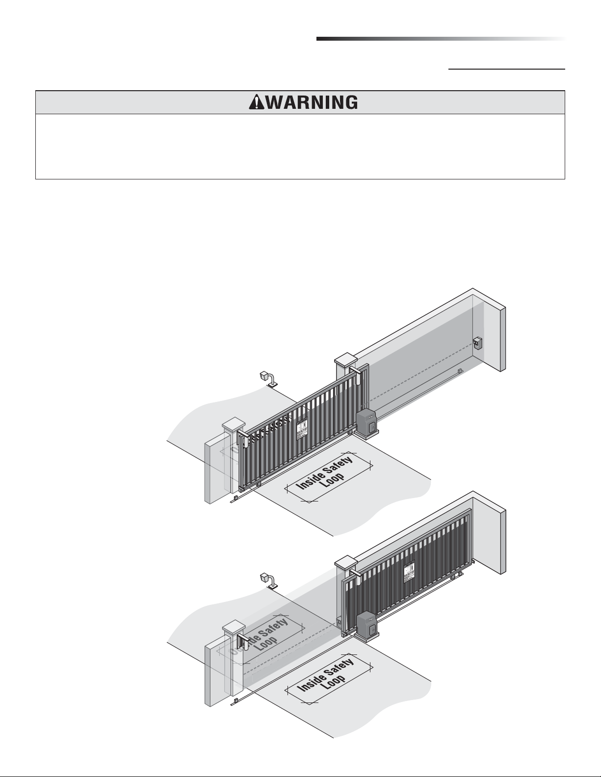
To prevent SERIOUS INJURY or DEATH from a moving gate:
• Entrapment protection devices MUST be installed to protect anyone who may come near a moving gate.
• Locate entrapment protection devices to protect in BOTH the open and close gate cycles.
• Locate entrapment protection devices to protect between moving gate and RIGID objects, such as posts or walls.
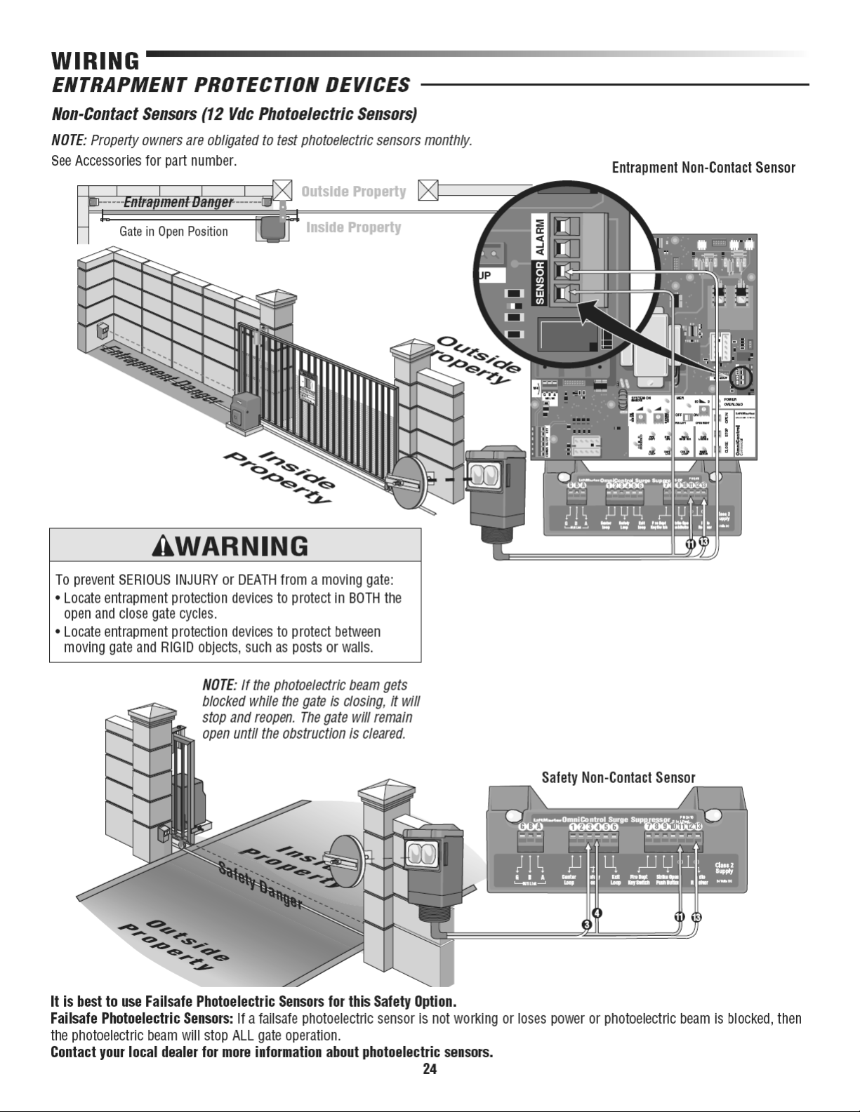
Non-Contact Sensors (Photoelectric Sensors)
Install photoelectric sensors to protect against any entrapment
or safety conditions encountered in your gate application.
See Entrapment Protection Devices.
Safety loops allow the gate to stay open when vehicles are
obstructing the gate path. Suggested for vehicles 14 feet or
longer.
See Loop Detector Wiring.
Gate Rail Stops For safety reasons, physical stops MUST be
installed on both ends of the gate rail prior to installation of the
gate operator. This will assure that the gate does not derail while
opening or closing fully.
Outside Property
Entrapment Danger
for OPEN Cycle
Inside Property
Outside Property
Safety Danger
for CLOSE Cycle
Inside Property
7
Page 10
Page 11
Page 12
Page 13
Page 14
Page 15
Page 16
Page 17
Page 18
Page 19
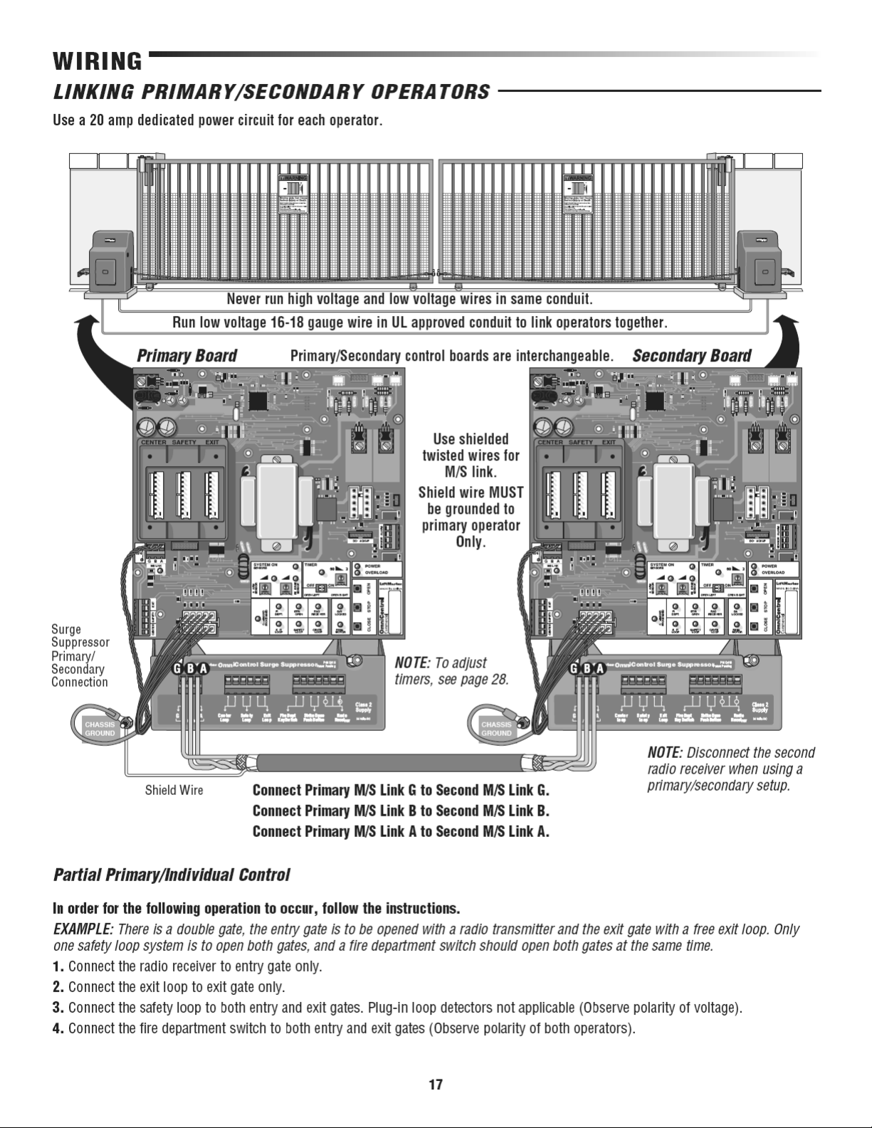
Page 20
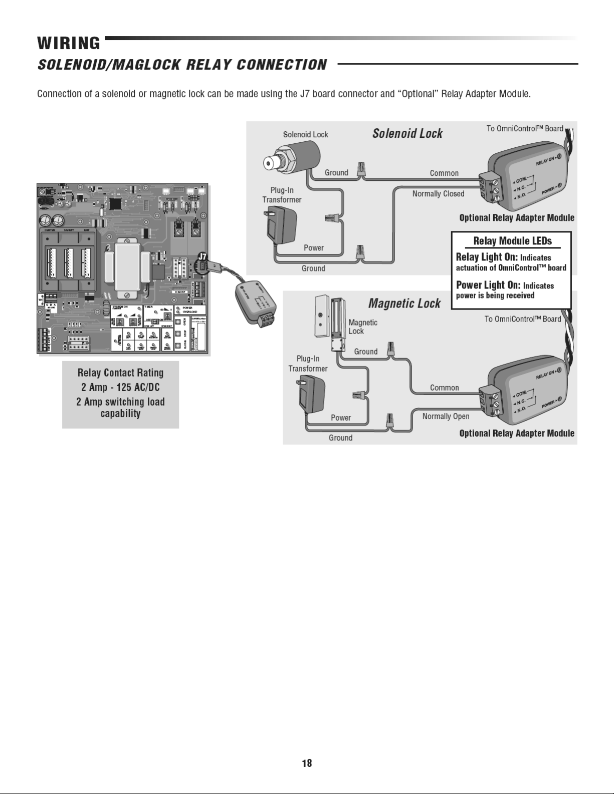
Page 21
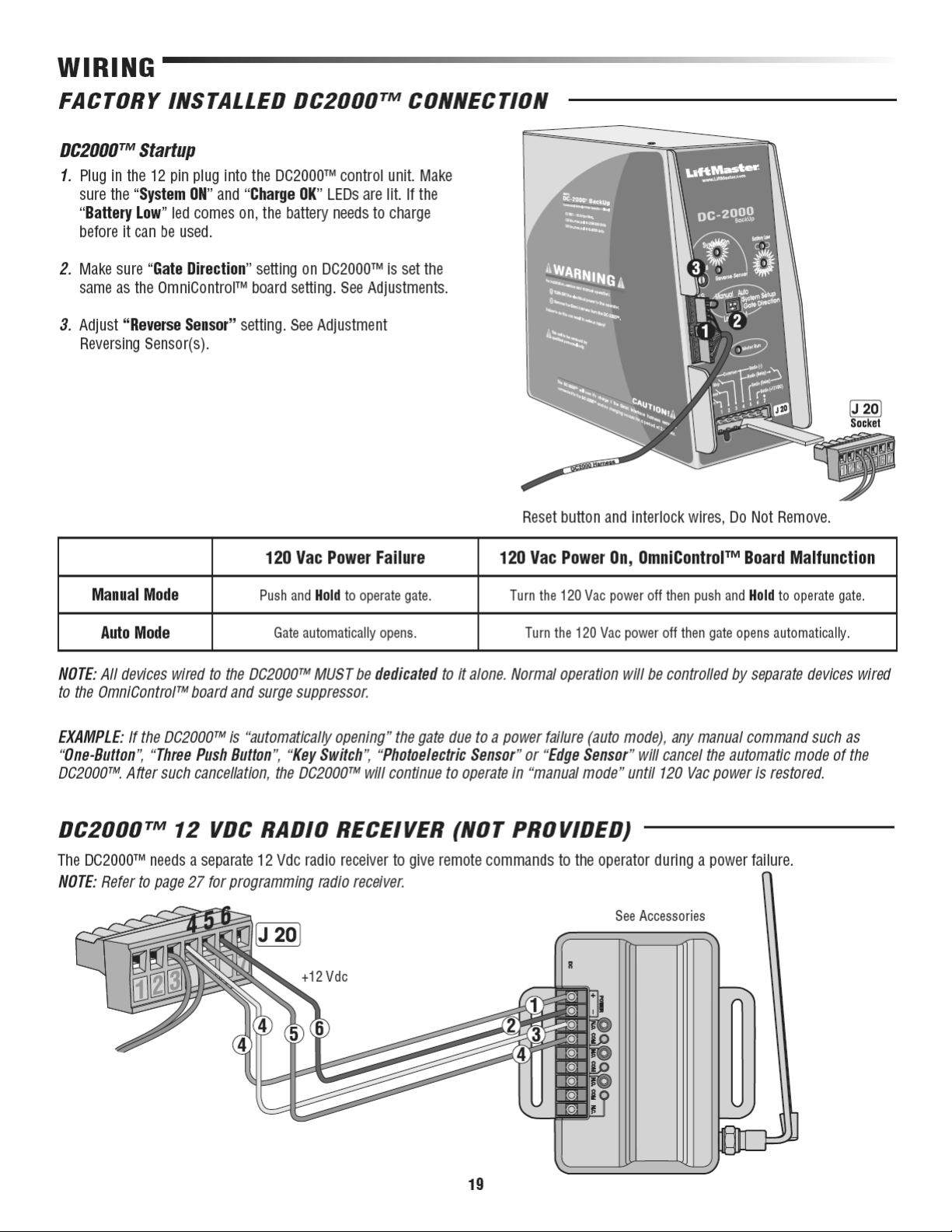
Page 22
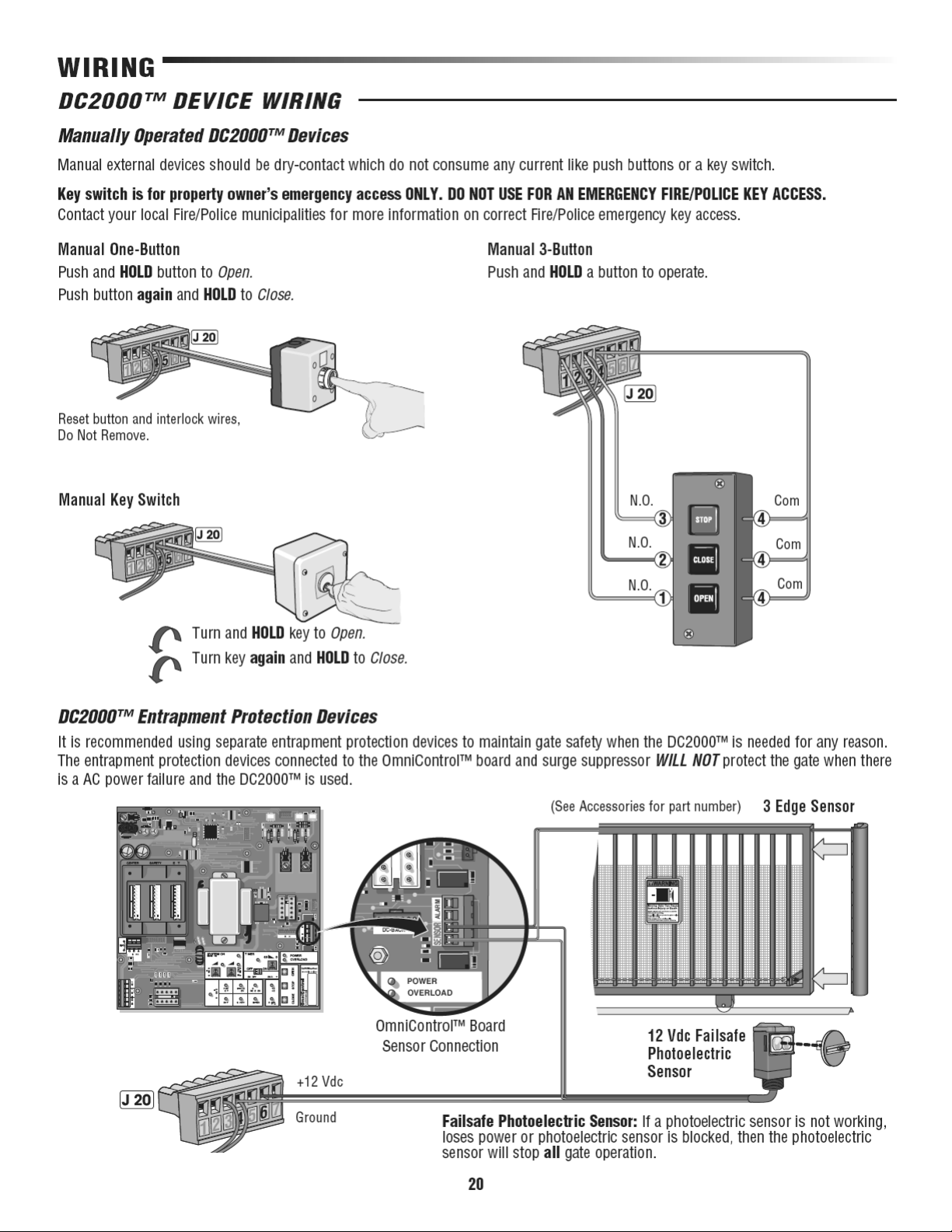
Page 23
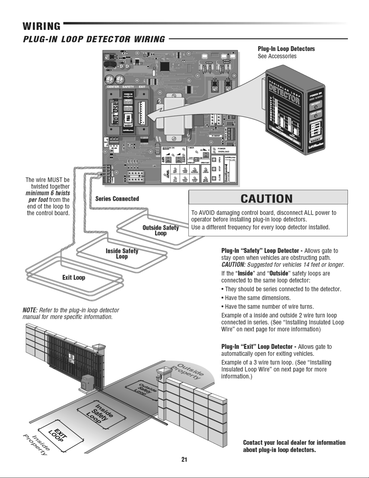
Page 24
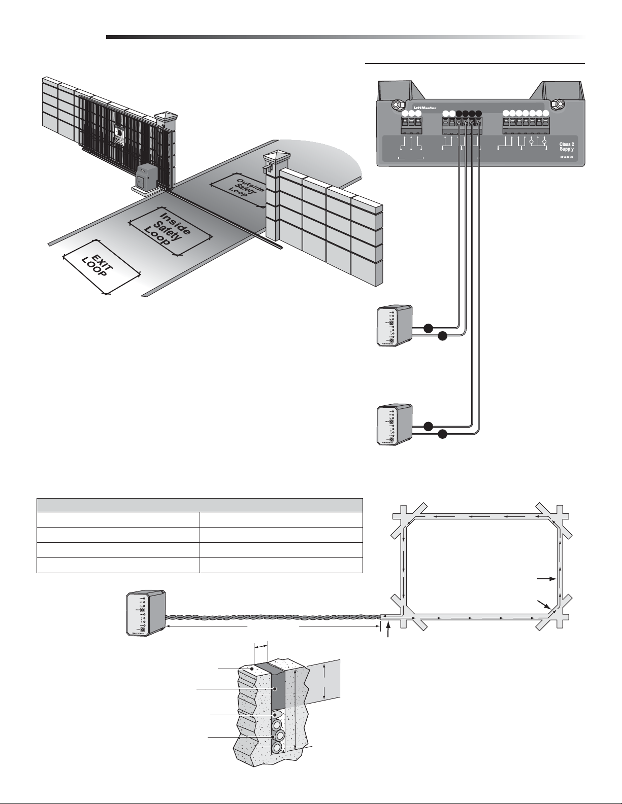
WIRING
120 VAC EXTERNAL LOOP DETECTOR WIRING
Outside
Property
Property
Inside
See Accessories
120 Vac “Safety” Loop Detector - Allows gate to stay open when vehicles are
obstructing path.
CAUTION: Suggested for vehicles 14 feet or longer. If a vehicle is shorter, a center
loop system is recommended and should be installed.
If the “Inside” and “Outside” safety loops are connected to the same loop detector:
• They should be series connected to the detector
• Have the same dimensions.
• Have the same number of wire turns (See table below).
120 Vac “Exit” Loop Detector - Allows gate to automatically open for
exiting vehicles.
GAB
GGBBAA
M/S LinkM/S Link
3
Safety Loop
5
Exit Loop
OmniControl Surge Suppressor
1 65432
Fire Dept
Center
Center
Loop
Loop
Safety
Safety
Loop
Loop
Fire Dept
Exit
Exit
Key Switch
Key Switch
Loop
Loop
4
6
7 121098
Strike Open
Strike Open
Push Button
Push Button
P/N Q410
P/N Q410
Patent Pending
Patent Pending
––
1311
++
Radio
Radio
Receiver
Receiver
Installing Insulated Loop Wire
Number of Wire Turns Needed for Loop Sizes
Loop Perimeter Number of Wire Turns
10 feet to 13 feet 4
14 feet to 26 feet 3
27 feet to 80 feet 2
80 feet and up 1
The wire MUST be twisted together minimum 6
twists per foot from the end of the feeder slot to the
loop detector.
1/8" to 1/4" Width Saw Cut
Contact your local dealer
for more information
about loop detectors.
Insulated loop wire
3 turns shown, amount varies.
Road Surface
Sealant
Backer Rod
Refer to table.
Home Run
Min 1"
2" to 2.5" Depth
Saw Cut
22
The wire is continuously wound in
the loop saw cut for the required
number of turns. One turn shown.
(Refer to table)
Saw Cut
Remove sharp inside corners
by making corner cuts
Feeder Slot
Recommended Loop Wire XLPE 12-18 gauge
(Use heavier wire gauge for a more durable loop).
NOTE: Wire mesh or reinforcement
embedded in the road surface should
be cut away a minimum of 6 inches
from the perimeter of the loop.
Page 25
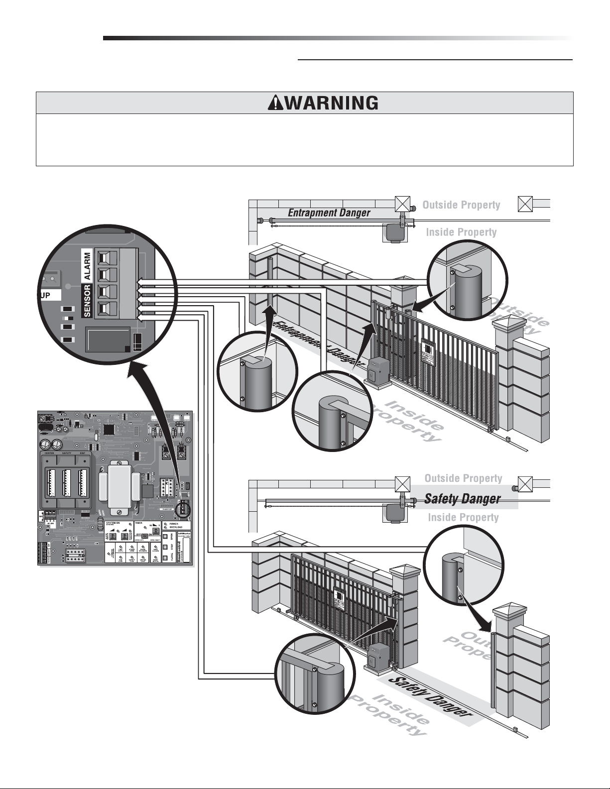
WIRING
ENTRAPMENT PROTECTION DEVICES
Contact Sensors (Edge Sensor)
To prevent SERIOUS INJURY or DEATH from a moving gate:
• Locate entrapment protection devices to protect in BOTH the open and close gate cycles.
• Locate entrapment protection devices to protect between moving gate and RIGID objects, such as posts or walls.
NOTE: When touched, these electrically activated edge sensors immediately signal the gate operator to stop and reverse. Property
owners are obligated to test edges monthly. See Accessories.
Gate in Open Position
Parallel
Connection
Open
Sensor
on Wall
Open Sensor
on Wall
Open Sensor on Gate
Gate in Open Position
Connect all edge sensors to the
sensor connection.
Close
Sensor
on Wall
Close Sensor on Gate
23
Page 26
Page 27
Page 28
Page 29
Page 30
Page 31

Page 32
Page 33
Page 34
Page 35
Page 36
CENTER SAFETY EXIT
CENTER SAFETY EXIT
13
TIMER
SYSTEM ON
ALARM
SENSOR
OPEN
STOPCLOSE
60
POWER
OVERLOAD
OFF
W4
OPEN LEFT
DC-BACKUP
ALARMSENSOR
OPEN RIGHT
3
SENSORS
13
13
ON
GB
MS LINK
A
FIRE
DEPT.
STRIKE
OPEN
RADIO
RECEIVER
EXIT
LOOP
REVERSE
SENSOR
SAFETY
LOOP
CENTER
LOOP
GATE
LOCKED
RESET
MOTOR
COMMAND
PROCESSED
J7
J9
1
2
3
4
5
6
J8
J2
J6
J5
J3
J1
3
1234567
4
3
J10
J11 J12 J13
123
Strike Open
Push Button
Strike Open
Push Button
Fire Dept
Key Switch
Fire Dept
Key Switch
M/S LinkM/S Link
Center
Loop
Center
Loop
Safety
Loop
Safety
Loop
Radio
Receiver
Radio
Receiver
Exit
Loop
Exit
Loop
GGBB
AA
––
++
OmniControl Surge Suppressor
P/N Q410
Patent Pending
P/N Q410
Patent Pending
J1 J3 J2
123 123456 1234567
Omni
Option Board
(Optional)
to
OmniControl™
Board
to
OmniControl™ Board
J2
Green
Chassis Ground
Reset Switch
Interlock
Assembly
NOTE: Reset switch and interlock assembly connection
differs when DC2000™ is used.
Radio Harness
Green
Green/
Black
White
Black
Red
UL Alarm
Limit Box
Assy
Left Right
NOTE: Limit
switch wiring
differs when
DC2000™ is
used.
Relay
Adapter
Module
(Optional)
Motor
Factory Heater
NOTE: Wires into
main power and
draws 3 amps.
OmniControl™ Board
Not Used
J10
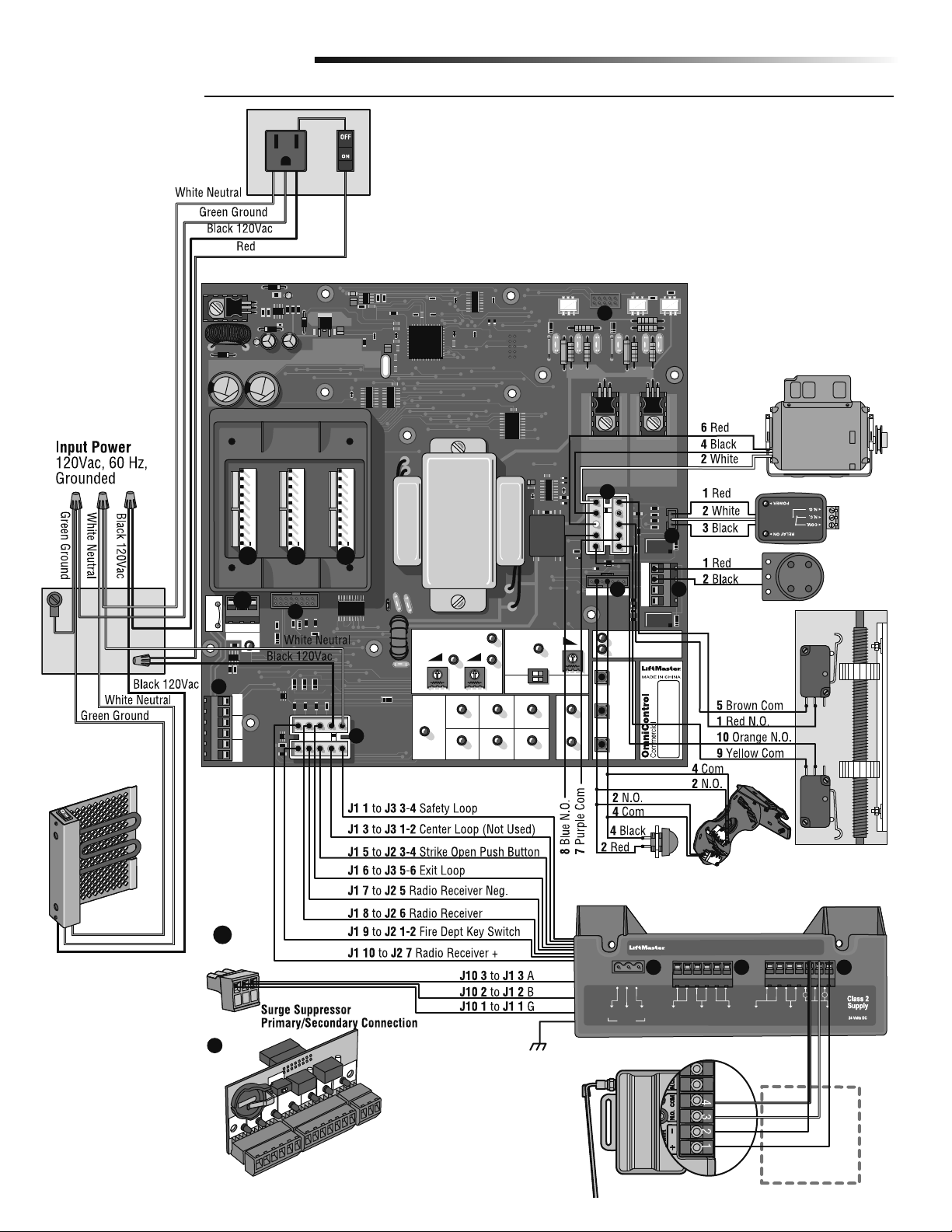
WIRING DIAGRAMS
SL3000UL8™
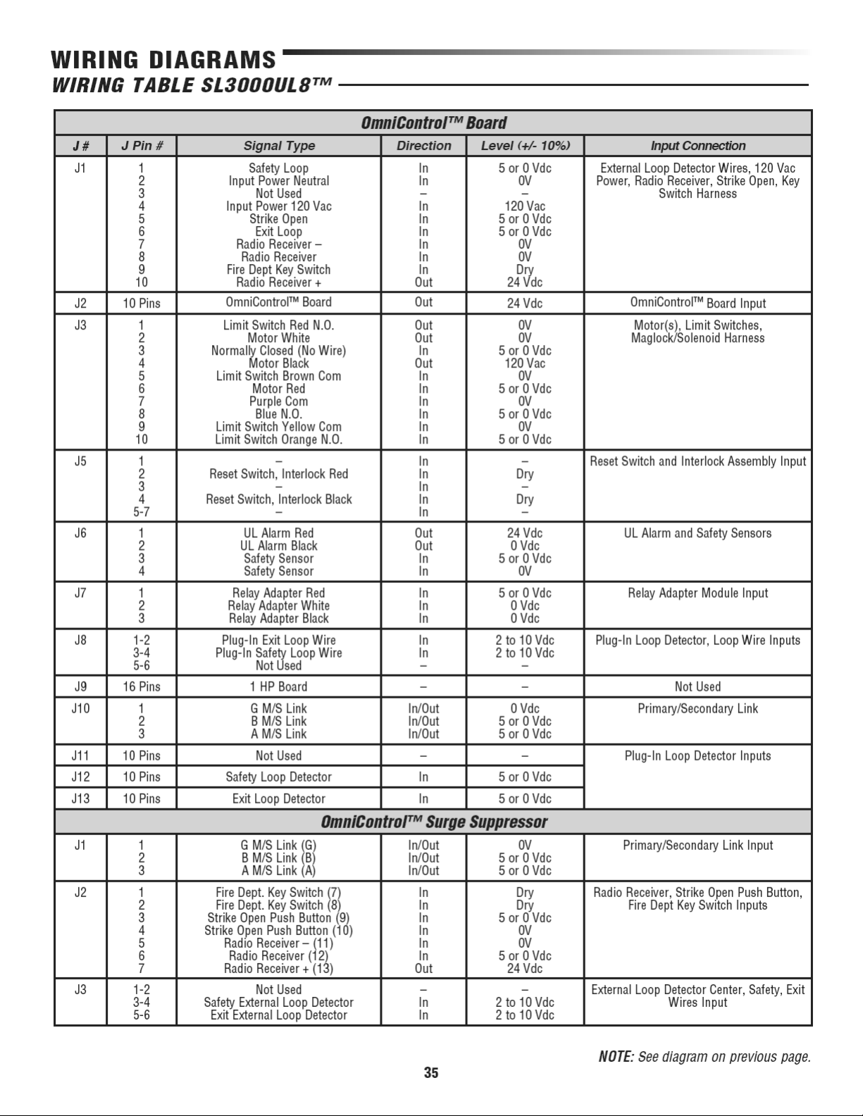
NOTE: See table on next page.
34
Page 37
Page 38
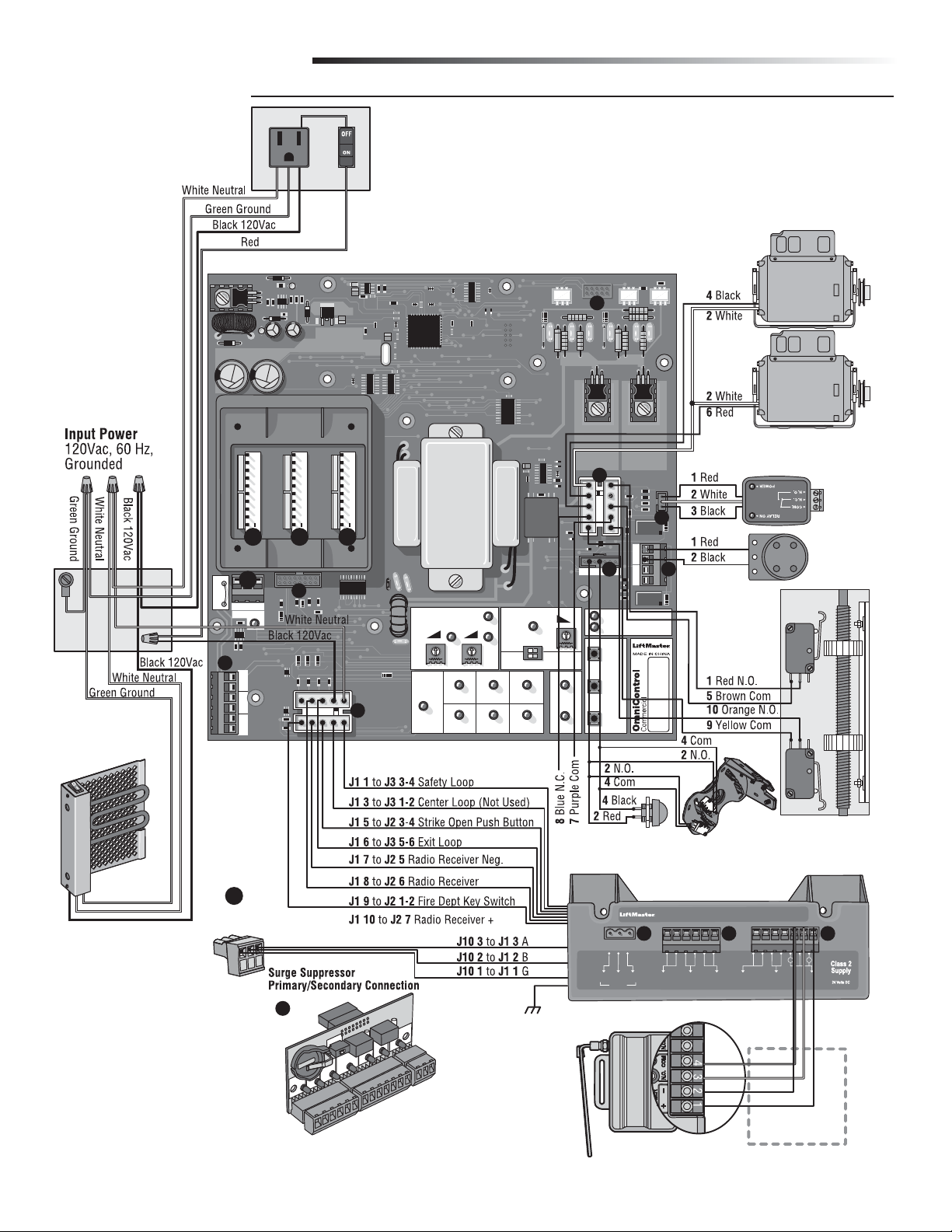
WIRING DIAGRAMS
SL3000ULDM8™
OmniControl™ Board
Factory Heater
NOTE: Wires into
main power and
draws 3 amps.
CENTER SAFETY EXIT
Not Used
J11 J12 J13
J10
W4
123
GB
MS LINK
J8
1
2
3
4
5
6
CENTER SAFETY EXIT
J2
A
J9
Motor
Motor
J3
3
J7
1234567
DC-BACKUP
SYSTEM ON
SENSORS
13
ALARM
SENSOR
FIRE
DEPT.
J1
COMMAND
PROCESSED
LOOP
EXIT
13
STRIKE
OPEN
SAFETY
LOOP
SENSOR
REVERSE
TIMER
OFF
OPEN LEFT
RECEIVER
RADIO
CENTER
LOOP
60
ON
OPEN RIGHT
13
GATE
LOCKED
RESET
MOTOR
3
J5
POWER
OVERLOAD
OPEN
STOPCLOSE
ALARMSENSOR
J6
3
4
NOTE: Limit
switch wiring
differs when
DC2000™ is
used.
Limit Box
Assy
UL Alarm
Left Right
Relay
Adapter
Module
(Optional)
J10
to
OmniControl™
Board
OmniControl™ Board
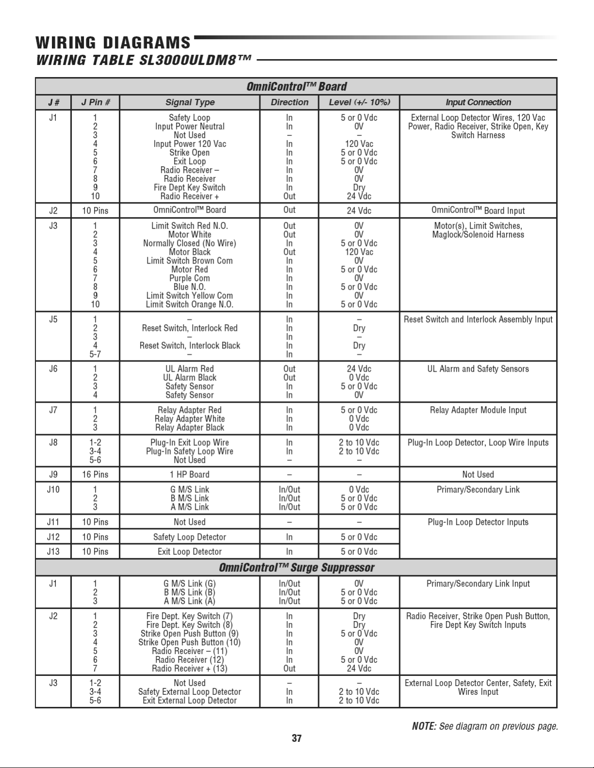
NOTE: See table on next page.
Interlock
Safety
Safety
Loop
Loop
Assembly
Exit
Exit
Fire Dept
Fire Dept
Loop
Loop
Key Switch
Key Switch
Green
White
Black
Red
P/N Q410
P/N Q410
Patent Pending
Patent Pending
++
––
Strike Open
Strike Open
Radio
Radio
Push Button
Push Button
Receiver
Receiver
Black
Green/
Radio Harness
Reset Switch
NOTE: Reset switch and interlock assembly connection
differs when DC2000™ is used.
123 123456 1234567
GG BB
Green
J2
to
Chassis Ground
OmniControl Surge Suppressor
J1 J3 J2
Center
Center
AA
Loop
M/S LinkM/S Link
Loop
Omni
Option Board
(Optional)
36
Page 39
Page 40
Page 41
Page 42
Page 43
Page 44
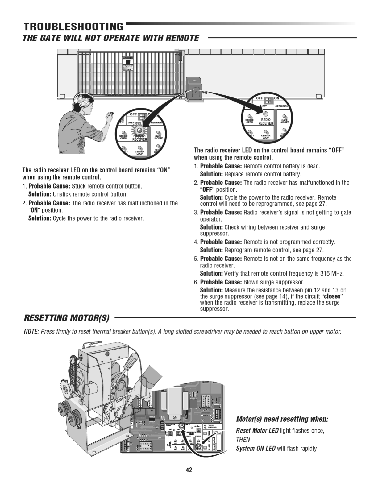
Page 45
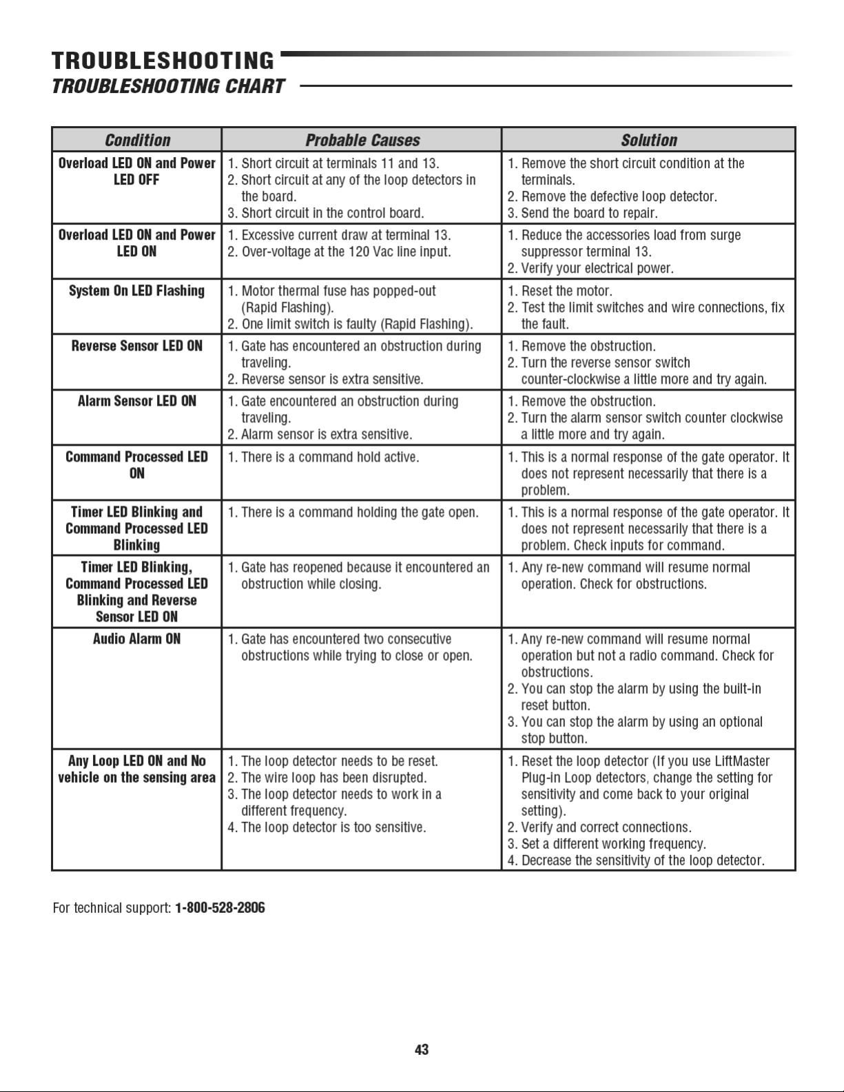
Page 46
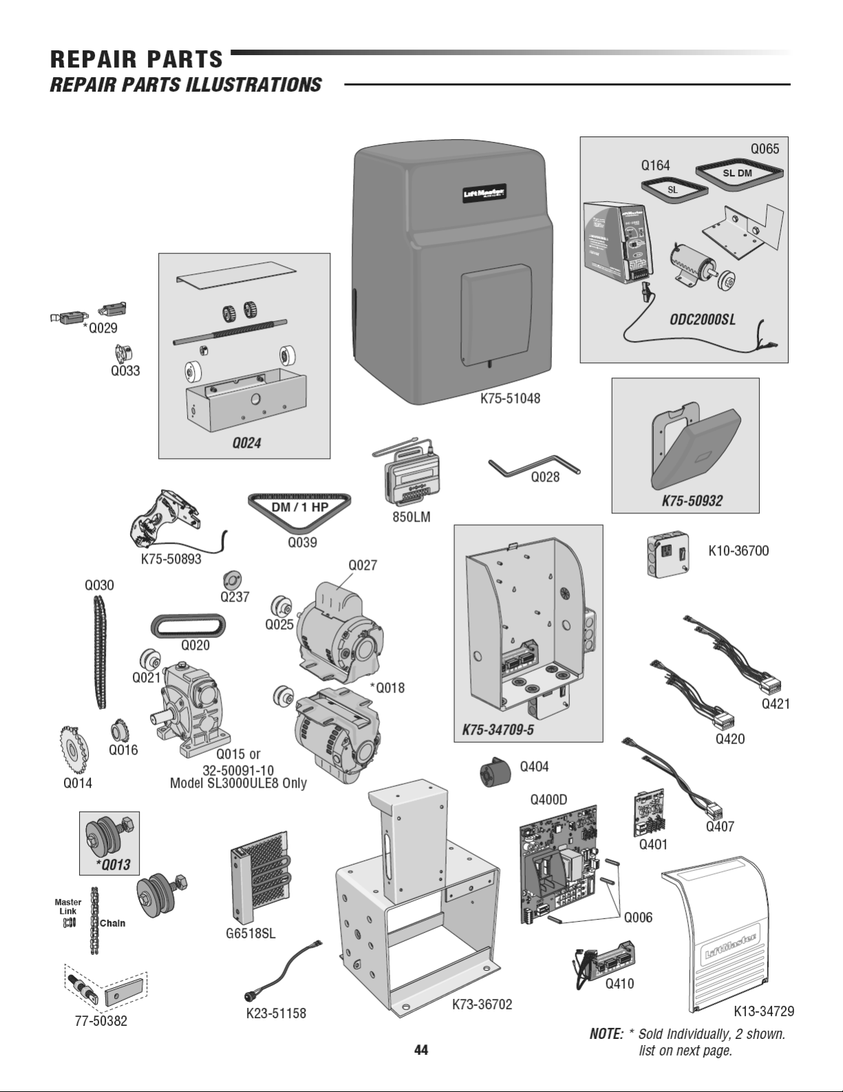
Page 47
REPAIR PARTS
HOW TO ORDER REPAIR PARTS
OUR LARGE SERVICE ORGANIZATION SPANS AMERICA. INSTALLATION AND SERVICE INFORMATION
IS AS NEAR AS YOUR TELEPHONE. SIMPLY DIAL OUR TOLL FREE NUMBER:
WHEN ORDERING REPAIR PARTS, ALWAYS GIVE THE FOLLOWING INFORMATION:
• PART NUMBER
• PART NAME
• MODEL NUMBER
REPAIR PART NAMES AND NUMBERS
1-800-528-2806
www.liftmaster.com
Address orders to:
THE CHAMBERLAIN GROUP, INC.
Technical Support Group
6050 S. Country Club Road
Tucson, Arizona 85706
Crank Housing Kit - K75-50932 - Manual Crank not Included
Power Back-Up Unit - ODC2000SL
- Drive Belt DC SL Q164
- Drive Belt DC SL (DM) Q065
- Back-Up Motor DC 12V
- Chassis DC Back-Up
- Hardware Kit for DC Back-Up
- Wire Harness DC2000
- Pulley DC2000 1/2 ID
Idler Pulley Assembly - Q013
- Bushing, 7/8" OD, .120" Wall x 1.950"
- Pulley, Idler, Molded Plastic, SL
- Screw, Hex, 5/8-11 x 2 3/4", Grade 5
- Nut, Hex, Jam, 5/8 -, S/Z
- Washer, Flat, 5/8", SAE, S/Z
Limit Switch Assembly - Q024
- Limit Switch Bolt
- Limit Switch Adjustment Nuts
- Limit Switch Sprocket
- Limit Switch Bearing Holder
- Collar 3/8"
Control Box Assembly - K75-34709-5
- Electronic Metal Box
- Surge Suppressor
- Audio Alarm
- Dust Guard
1941240D - Chain no. 41 (10 ft)
1940240D - Chain no. 40 (10 ft)
1941240DNP - Chain no. 41 (Nickel Plated)
1950307 - Master Link no. 41
1950310 - Master Link no. 40
K23-51158 - Reset Switch Assembly
K75-50893 - Safety and Interlock Assembly
G6518SL - Heater
K73-36702 - SL-3000 Chassis
K82-PX06-05 - PC Board Screws
Q014 - Drive Sprocket
Q015 - Gear Reducer
32-50091-10 - Gear Reducer (Model SL3000ULE8 only)
Q016 - Limit Switch Drive Sprocket
Q018 - 1/2 HP Electric Motor
Q020 - Drive Belt
Q021 - Gear Pulley
Q025 - Motor Pulley
Q027 - Motor Capacitor
Q028 - Manual Crank
Q029 - Limit Switch
Q030 - Limit Switch/Chain
Q039 - Drive Belt, DM and 1 HP
Q237 - Crank Input
K75-51048 - Cover HD Polyethylene SL
Q400D - Omni Main PCB (OmniControl™)
Q401 - Omni 1 HP Board
Q404 - Omni Siren
Q407 - Omni Motor Harness 1 HP
K10-36700 - Junction Box with On/Off Switch and Receptacle
K13-34729 - Dust Guard
Q410 - Surge Suppressor Terminal Block
Q420 - Omni Motor Harness Single Motor
Q421 - Omni Motor Harness DM
850LM - Radio Receiver
Hardware Kit - 77-50382
- Chain Bolt
- Chain Bracket
NOTE:
Assembly Parts Number
45
Page 48

SYSTEM DIAGRAM
46
Page 49
Page 50

WARRANTY POLICY
7 YEAR RESIDENTIAL / 5 YEAR COMMERCIAL SL3000UL8™ LIMITED WARRANTY
The Chamberlain Group, Inc. (“Seller”) warrants to the first purchaser of this product, for the structure in which this product is
originally installed, that it is free from defect in materials and/or workmanship for a period of 7 year residential/ 5 year commercial
from the date of purchase [and that the SL3000UL8™ is free from defect in materials and/or workmanship for a period of 7 year
residential/ 5 year commercial from the date of purchase]. The proper operation of this product is dependent on your compliance with
the instructions regarding installation, operation, maintenance and testing. Failure to comply strictly with those instructions will void
this limited warranty in its entirety.
If, during the limited warranty period, this product appears to contain a defect covered by this limited warranty, call 1-800-528-2806,
toll free, before dismantling this product. Then send this product, pre-paid and insured, to our service center for warranty repair. You
will be advised of shipping instructions when you call. Please include a brief description of the problem and a dated proof-of-purchase
receipt with any product returned for warranty repair. Products returned to Seller for warranty repair, which upon receipt by Seller are
confirmed to be defective and covered by this limited warranty, will be repaired or replaced (at Seller’s sole option) at no cost to you
and returned pre-paid. Defective parts will be repaired or replaced with new or factory-rebuilt parts at Seller’s sole option.
ALL IMPLIED WARRANTIES FOR THE PRODUCT, INCLUDING BUT NOT LIMITED TO ANY IMPLIED WARRANTIES OF MERCHANTABILITY
AND FITNESS FOR A PARTICULAR PURPOSE, ARE LIMITED IN DURATION TO THE 7 YEAR RESIDENTIAL/ 5 YEAR COMMERCIAL LIMITED
WARRANTY PERIOD SET FORTH ABOVE [EXCEPT THE IMPLIED WARRANTIES WITH RESPECT TO THE SL3000UL8™, WHICH ARE
LIMITED IN DURATION TO THE 7 YEAR RESIDENTIAL/ 5 YEAR COMMERCIAL LIMITED WARRANTY PERIOD FOR THE SL3000UL8™], AND
NO IMPLIED WARRANTIES WILL EXIST OR APPLY AFTER SUCH PERIOD. Some States do not allow limitations on how long an
implied warranty lasts, so the above limitation may not apply to you. THIS LIMITED WARRANTY DOES NOT COVER NON-DEFECT
DAMAGE, DAMAGE CAUSED BY IMPROPER INSTALLATION, OPERATION OR CARE (INCLUDING, BUT NOT LIMITED TO ABUSE, MISUSE,
FAILURE TO PROVIDE REASONABLE AND NECESSARY MAINTENANCE, UNAUTHORIZED REPAIRS OR ANY ALTERATIONS TO THIS
PRODUCT), LABOR CHARGES FOR REINSTALLING A REPAIRED OR REPLACED UNIT, OR REPLACEMENT OF BATTERIES.
THIS LIMITED WARRANTY DOES NOT COVER ANY PROBLEMS WITH, OR RELATING TO, THE GARAGE DOOR OR GARAGE DOOR
HARDWARE, INCLUDING BUT NOT LIMITED TO THE DOOR SPRINGS, DOOR ROLLERS, DOOR ALIGNMENT OR HINGES. THIS LIMITED
WARRANTY ALSO DOES NOT COVER ANY PROBLEMS CAUSED BY INTERFERENCE. ANY SERVICE CALL THAT DETERMINES THE
PROBLEM HAS BEEN CAUSED BY ANY OF THESE ITEMS COULD RESULT IN A FEE TO YOU.
UNDER NO CIRCUMSTANCES SHALL SELLER BE LIABLE FOR CONSEQUENTIAL, INCIDENTAL OR SPECIAL DAMAGES ARISING IN
CONNECTION WITH USE, OR INABILITY TO USE, THIS PRODUCT. IN NO EVENT SHALL SELLER’S LIABILITY FOR BREACH OF WARRANTY,
BREACH OF CONTRACT, NEGLIGENCE OR STRICT LIABILITY EXCEED THE COST OF THE PRODUCT COVERED HEREBY. NO PERSON IS
AUTHORIZED TO ASSUME FOR US ANY OTHER LIABILITY IN CONNECTION WITH THE SALE OF THIS PRODUCT.
Some states do not allow the exclusion or limitation of consequential, incidental or special damages, so the above limitation or
exclusion may not apply to you. This limited warranty gives you specific legal rights, and you may also have other rights which vary
from state to state.
48
Page 51

Page 52

845 Larch Avenue
Elmhurst, Illinois 60126-1196
01-36718 © 2012, The Chamberlain Group, Inc. – All Rights Reserved
 Loading...