

Page 1

Easy step-by-step
interactive 3D instructions
for this product can be found in
DOWNLOAD THE FREE APP
Availableon most iOS and AndroidDevices
AFTER YOUR ASSEMBLY WITH BILT,
DOWNLOAD THE myQ® APP
Installation Manual Inside
Page 2

Page 3

Installation Manual
Belt Drive Garage Door Opener
Models B2202 • B2212T • B2405 • B4505T
FOR RESIDENTIAL USE ONLY
PREǫPROGRAMMED REMOTE
CONTROL INCLUDED
To register your garage door opener to receive
updates and offers from Chamberlain, visit
chamberlain.registria.com or use the icon below:
1. Take a photo of the camera icon including
the points (
2. Send it in by texting the photo to 71403 (US).
).
www.chamberlain.com
• Please read this manual and the enclosed safety materials carefully!
• Fasten the manual near the garage door after installation.
• The door WILL NOT CLOSE unless the Protector System® is connected and properly aligned.
• Periodic checks of the garage door opener are required to ensure safe operation.
• The model number label is located on the left side panel of your garage door opener.
• This garage door opener is compatible with myQ® and Security+2.0® accessories.
• DO NOT install on a one-piece door if using devices or features providing unattended close. Unattended
devices and features are to be used ONLY with sectional doors.
Page 4

Contents
Preparation 5 Assembly 9 Installation 14
Install the Door Control 24
Install the Protector System® 27
Connect Power 31
Adjustments 33
Battery Backup 36
myQ® App Control 37
Connect WithYour Smartphone 37
Operation 38
Usingyour Garage Door Opener 38
Usingyour Door Control 39
Remote Controland Keyless Entry 41
HomeLink® 41
Erase the Memory 42
To Open the Door Manually 42
Maintenance 43
Troubleshooting 44
Warranty 46
Automatic Garage Door Opener Safety & Maintenance Guide 47
Repair Parts 49
Rail AssemblyParts 49
Installation Parts 49
Models B2202and B2212T 50
Models B2405and B4505T 51
Safety Symbol and Signal Word Review
This garage door opener has been designed and tested to offer safe service p rovided it is installed, operated,
maintained and tested in strict accordance with th e instructions and warnings contained in this manual.
Mechanical
Electrical
When you see thes e Safety Symb ols and Signal Words on the following pages, t hey will alert youto the
possibility of serious injury or death if youdo not comp ly with th e warnin gs th at accomp any them. The
hazard may come from someth ing mechanical or from electric shock. Read th e warnings carefully.
When you see this Signal Word on the following pages, it will alert you to the possibility of d amage to your
garage door and/or the garage door opener if you do not comply with the cautionary statements that
accompany it. Read t hem carefully.
WARNING: This product can expose you t o ch emicals including lead, which are known to the State of
California to cause cancer or birth defects or other reproductive harm. For more information go to
www.P65Warn ings.ca.gov
Unattended Operation
The Timer-to-Close (TTC) f eature, t he myQ® App, and myQ® Garage Door and Gate Monitor are examples of
unattended close and are to b e used ONLY with sectional doors. An y device or feature that allows the door to
close with out being in the line of sight of the door is considered unattend ed close. The Timer-to-Close (TTC)
feature, the myQ® App, and any other myQ® devices are to be used ONLYwith sectional doors.
The images throughout this manual are for reference only and your product may
look different.
4
Page 5

Torsion
Spring
Extension
Spring
Wi-Fi signal is weak.
The garage door opener will likely connect to your Wi-Fi
network. If not, try one of the options below.
No Wi-Fi signal. Try one of the following:
• Move your router closer to the garage door opener to
minimize interference from walls and other objects
• Buy a Wi-Fi range extender
Check Signal Strength. If you see:
Wi-Fi signal is strong. You’re all set!
Install your new garage door opener.
Preparation
Check the Door
To prevent possible SERIOUSINJURYor DEATH:
l ALWAYS call a trained door s yst ems technician if garage door bin ds, s ticks, or is out of b alance. An
unbalanced garage door m ay NOT reverse when required.
l NEVER try to loosen, move or adjust garage door, door spring s, cables, pulleys, brackets or their
hardware, ALLof which are under EXTREME tens ion.
l Disable ALLlocks and remove ALLropes connected to garage door BEFORE ins tallation and operating
garage door opener to avoid entanglement.
l DO NOT install on a one-piece door if using devices or features providing unatt ended close.
Unattended devices and features are to be used ONLY with sectional d oors.
To prevent damage t o garage door and opener:
l ALWAYS d isable locks BEFORE installing and operating the open er.
l ONLY operate garage door opener at 120V, 6 0H z to avoid malfunction and damage.
Before youb egin:
1. Disable locks and remove any ropes connected to t he garage door.
2. Lift the door halfway up. Release t he door. If balanced, it should stay in place, supp orted entirely b y its
springs .
3. Raise and lower the door to check for bindin g or sticking. If your door bin ds, s ticks, or is out of b alance,
call a trained door systems technician.
4. Check t he seal on the bottom of the door. Any gap between the floor and th e bottom of the door must
not exceed 1/4" (6 mm). Otherwise, t he safety reversal s ystem may not work properly.
5. The opener should be installed above the center of the d oor. If there is a torsion spring or cent er
bearing plate in the way of the header bracket, it m ay be in stalled within 4feet (1.2 m) to the left or
right of the door cent er. See page 15.
Before You Connect with Your Smartphone
Monitor and control your garage d oor from anywhere usin g the myQ® App. Youwill need a router with Wi-Fi®
and a s martphone or other mobile device. Make sure your mobile device is conn ected to your Wi-Fi® network.
Hold your mobile device in the place where your garage d oor opener will be installed and check the Wi-Fi®
sign al streng th.
Visit support.chamberlaingroup.com for more details.
See myQ® App Control page 37 to connect your g arage door opener to your Wi-Fi® network.
5
Page 6

3/16
7/16
1/2
5/32
5/16
9/16
1/4
7/16
Support Brackets
Hardware x2 (each)
Extension Brackets –Ê041A5281-1
Lag screws x4
Lag screws x12
Wood Blocks
Preparation
Tools Needed
Additional Items You May Need:
Survey your garage area to see if you will need any of the following items:
l (2) 2X4 Pieces of wood : May be used to fasten the h eader bracket to th e structural supports. Also
used to position the garage door opener d uring installation and for t esting the safet y reversing
sens ors.
l Support bracket and fastening hardware: Must be used if you have a finis hed ceiling in your garage.
l Extension brackets (Model 041A5281-1) or wood blocks: Depend ing upon garage construction,
extens ion brackets or wood b locks may b e needed to in stall the safety reversin g sens or.
l Fastening hardware: Altern ate floor mountin g of the safety reversing sensor will require hardware n ot
provided .
l Doo r reinfo rcement: Required if you have a lightweigh t steel, alumin um, fiberglass or glass panel door.
l Railextension kit: Required if your garage door is more than 7 feet (2.13 m) high.
6
Page 7

9 x2
14 x2
2
8 x1
7
7
18
12
8 x4
14 x1
14 x1
11
6
10
3
5
1
16
19
20
17
13
4
15
Preparation
Carton Inventory
Save the carton and packing material unt il the installation and adjustment is complete. Instructions for the
accessories will be attached to the accessory and are not in cluded in this manual. The images throughout th is
manual are for reference only and your product may look d iff erent.
1. H eader bracket
2. P ulley
3. Door b racket
4. Curved door arm
5. S traigh t door arm
(Packaged insid e front rail section)
6. Trolley
7. Emerg ency release rope and handle
8. Rail (1 front and 4 center sections)
9. H angin g brackets (2)
10. Garage door opener (motor unit)
11. Sprocket cover and s crews
12. “U” bracket
13. Belt
14. The Protector System
15. Battery Backup - Model B221 2T
16. Remote control
17. Wireless keypad - Models B2405 and B45 05T
18. Push Button Door Control - Models B22 02 and B2212T
19. White and red/white wire
20. Installation manual and all warning labels
See Hardware p age 8.
Go to chamberlain.com for replacement or additional accessories:
3-button remote control m odel 953EV-P2
Wireless keypad model 940EV-P 2
(Packaged insid e the front rail s ection)
Safety reversing sen sors with 2 cond uctor white and white/black wire attached: sending sensor (1),
receiving sensor (1), and safety sens or brackets (2)
®
Multi-Function Control P anel - M odel B2405
Motion Detecting Control Panel - Model B4505
7
Page 8

ASSEMBLY INSTALLATION
Clevis Pin 5/16"x1-1/2"
Ring
Fastener (3)
Hex Bolt 5/16"-18x7/8" (4)
Self-Threading Screw
1/4"-14x5/8" (2)
Clevis Pin 5/16"x1" Clevis Pin 5/16"x1-1/4"
Hex Screw 10-24 (2)
Wing Nut (2)
Lag Screw 5/16"-9x1-5/8" (4)
Hex Screw #8x3/8" (3)
(packed with the
sprocket cover)
Bolt 1/4"-20x1-3/4"
Lock Nut
1/4"-20
Bolt
Nut 3/8"
Lock Washer 3/8"
Master Link
Threaded
Shaft with
Spring
Trolley Nut
Lock Washer
5/16"-18 (4)
Nut
5/16"-18 (4)
DOOR CONTROL
Insulated Staples
(Not Shown)
Screw 6ABx1" (2)
Screw
6ABx1-1/2" (2)
Drywall Anchors (2)
Models B2405 and B4505T
Models B2202 and B2212T
Drywall
Anchors (2)
Screw 6-32x1" (2)
Preparation
Hardware
8
Page 9

Assembly
Wear Pads
Front Rail Section
(TO DOOR)
“U” Bracket
(TO MOTOR UNIT)
Trolley
Rail Tab
On Top
Slide to stops
on top and sides
of “U” bracket
Screwdriver
STEP 1 Assemble the Rail and Install the Trolley
To prevent INJURY from pinching, keep hands and fingers away f rom the joints while assemb ling th e rail.
To avoid installation difficulties, do not ru n the garage door o pener until instructed to do so.
The front rail h as a cut out “window” at the door end. The rail tab MUST be on top ofthe rail when assembled.
1. Rem ove t he straight door arm and hanging bracket packaged inside the front rail and set aside for
Installation S tep 5 and 9. NOTE: To preven t INJURY while unp acking the rail carefully remove the
straight d oor arm st ored within the rail section.
2. Alig n the rail s ections on a flat surface as sh own and slide the tapered ends into the larger ones. Tabs
along the side willlock int o p lace.
3. P lace the motor unit on packing material to protect the cover, and rest the back en d of the rail on top.
For conven ience, put asupport und er the front end of the rail.
4. As a temporary s top, insert a screwdriver into the hole in the s econd rail s ection from the motor unit,
as shown.
5. Check t o b e sure th ere are 4 plastic wear pads inside t he inner trolley. If they became loose during
shippin g, check allpacking material. Snap them back into p osition as shown.
6. S lide the trolley assemb ly toward the s crewdriver as shown.
7. S lide the rail onto th e “U” bracket, unt il it reaches all th e stops on the top and sides of the “U” b racket.
9
Page 10

Assembly
Bolt
1/4"-20x1-3/4"
Lock Nut
1/4"-20
HARDWARE
Bolts (Mounted in the
garage door opener)
Bolt
Lock Nut
Cover Protection
Bolt Hole
“U” Bracket
STEP 2 Fasten the Rail to the Motor Unit
To avoid SERIOUS d amage to garage d oor opener, use ONLYthose bolts/fasteners mounted in the top of
the opener.
1. Insert a 1/4"-20 x 1-3/4" bolt into the cover protection bolt h ole on the b ack en d of the rail as shown.
Tighten securely with a 1/4"-20 lock nut. DO NOT overtight en.
2. Rem ove t he bolts from the top of the m otor unit.
3. Use the carton to support the front end of the rail.
4. P lace the “U” bracket, flat side down onto the motor unit and align the bracket h oles with th e bolt
holes.
5. Fast en the “U” b racket with the previously rem oved bolts; DO NOT use any power t ools. The use of power
tools may permanen tly damage the garage door opener.
10
Page 11

Assembly
Rail
Idler Pulley
Grease Inside
Pulley
Bolt
Belt
Lock Washer
Nut
Bolt
Nut 3/8" Lock Washer 3/8"
HARDWARE
Trolley Connector
Rail Tab
STEP 3 Install the Idler Pulley
1. Lay the belt beside t he rail, as sh own. Grasp th e end with th e hooked trolley conn ector and pass
approximately 12" (30 cm) of belt through the wind ow. Keep the ribbed side toward the rail, and allow
it to hang until Assembly Step 4.
2. Rem ove t he tape from the idler pulley. The inside cen ter should be pre-greased. If d ry, regrease to
ensure proper operation.
3. P lace the idler pulley int o the window as shown.
4. Insert the id ler bolt f rom the top through the rail an d pulley. Tigh ten with a 3/8" lock washer and nut
5. Rotate t he pulley to be s ure it spins f reely.
6. Locate the rail tab. The rail tab is b etween the idler bolt and the trolley in the front rail s ection. Use a
underneath the rail unt il the lock washer is comp ress ed.
flathead screwdriver and lift the rail tab until t he tab is vertical (90º).
11
Page 12
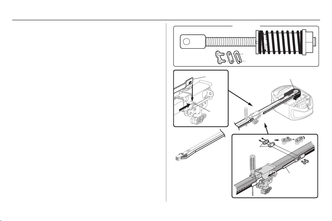
Assembly
HARDWARE
Master Link
Figure 3
Threaded Shaft with Spring Trolley Nut
Threaded Shaft
Master Link
Sprocket
Figure 2
Figure 1
Trolley
Connector
Retaining
Slot
STEP 4 Install the Belt
1. P ull the belt around the id ler pulley and toward the trolley. The ribbed side must contact the pulley.
2. H ook the t rolley conn ector into the retaining slot on t he trolley as shown (Figure1).
3. With the trolley against th e screwdriver, dispen se the remaind er of the b elt along the rail
lengthtoward t he motor unit and around the sprocket (Figure2). The sprocket teeth must engage the
belt.
4. Check t o m ake s ure t he belt is not twist ed. Connect the trolley t hreaded shaft with the mast er link
(Figure3).
a. Push pins of master link bar through holes in en d of belt and trolley th readed shaft.
b. P ush mast er link cap over pins and past pin notches.
c. Slid e the closed end of the clip-on spring over one of the p ins. Push the open end of the clip-on
spring onto the other pin.
5. Rem ove t he spring trolley nut f rom the threaded shaft .
6. Insert the t rolley threaded shaft th rough the hole in th e trolley.
12
Page 13

Assembly
Spring
Trolley Nut
Nut Ring Slot
Nut RingNut Ring
AFTER
1-1/4" (3.18 cm)
BEFORE
1" (2.5 cm)
Hex Screw #8x3/8"
(Packed with the sprocket cover)
HARDWARE
Hex Screw
Sprocket Cover
STEP 5 Tighten the Belt
1. By hand, thread the s pring trolley nut on the t hreaded shaft until it is finger tight against the trolley.
Do not use an y tools. Remove the screwdriver.
2. Insert a flathead screwdriver tip into one of the n ut ring slots and brace it firmly against th e trolley.
3. Tigh ten the spring trolley nut with an adjustable wrench or a 7/16" open end wrench about aquarter
turn until the spring releases and snaps the nut ring against th e trolley. This sets the spring to
optimum belt tension.
STEP 6 Install the Sprocket Cover
To avoid possible SERIOUS INJURYto f ing er from moving garage door opener:
l ALWAYS keep hand clear of sprocket while operating opener.
l Securely attach sprocket cover BEFORE operating.
1. P osition the sprocket cover over the sprocket as shown an d fasten to the mounting plate with #8x3/ 8"
hex screws provided.
You have now finished assembling you r garage door opener. Please read the fo llowing warnings before
proceeding to the installation section.
13
Page 14

Installation
IMPORTANT INSTALLATION INSTRUCTIONS
To reduce the risk of SEVERE INJURY or DEATH:
1. READ AND FOLLOW ALL INSTALLATION WARNINGS AND INSTRUCTIONS.
2. Install garage door opener ONLY on properly balanced and lubricated garage door. An improperly
balanced door m ay NOT reverse when required and could result in SEVERE INJURY or DEATH.
3. ALL repairs to cables, spring ass emb lies and other hardware MUST b e made by atrained door
systems technician BEFORE in stalling opener.
4. Disable ALL locks and remove ALLropes connected to garage door BEFORE installing opener to avoid
entanglement.
5. Wh ere possible, inst all t he door opener 7 feet (2.13 m) or more above the floor.
6. Mount the emergency release within reach, but at least 6 feet (1.83 m) above th e floor and avoiding
contact with vehicles to avoid accidental release.
7. NEVER conn ect garage door opener to power s ource until instructed to do so.
8. NEVER wear watches, rings or loose cloth ing while installing or servicing opener. They could be caught
in garage door or open er mechanisms.
9. Install wall-mount ed garage door control:
l within sight of the garage door.
l out of reach of small children at a minimum height of 5feet (1.5m) above floors, landing s, steps
or any other adjacent walking surface.
l away from ALL moving parts of the door.
10. Place en trapm ent warning label on wall next to garage door control in a promin ent location.
11. Place em ergency release/safety reverse test label in p lain view on inside of garage door.
12. Upon completion of installation, test safety reversal system. Door M UST reverse on contact with a 11/2" (3.8cm) high object (or a 2x4 laid f lat) on the floor.
13. DO NOT install on aone-piece door if using devices or features providing unatten ded close.
Unattended devices and features are to be used ONLY with sectional d oors.
14. SAVE THESE INSTRUCTIONS.
14
Page 15

Installation
Header Wall
Vertical Centerline of Garage Door
2x4
Structural
Supports
Level
(Optional)
Unfinished
Ceiling
2x4
OPTIONAL CEILING MOUNT
FOR HEADER BRACKET
Sectional door with curved track
Header Wall
Track
2" (5 cm)
Highest
Point of
Travel
Door
One-piece door with horizontal track
Header Wall
Track
2" (5 cm)
Highest
Point of
Travel
Door
One-piece door without track:
jamb hardware
Header Wall
8" (20 cm)
Highest
Point of
Travel
Door
Jamb
Hardware
One-piece door without track:
pivot hardware
Header Wall
8" (20 cm)
Highest
Point of
Travel
Door
Pivot
STEP 1 Determine the Header Bracket Location
To prevent possible SERIOUS INJURY or DEATH:
l Header bracket MUST be RIGIDLYfastened to structural s upport on header wall or ceiling, otherwise
garage door m ight NOT reverse when required. DO NOT in stall header bracket over drywall.
l Concrete anchors MUST be used if mounting header bracket or 2x4 into masonry.
l NEVER try to loosen, move or adjust garage door, sp rings, cables, pulleys, brackets, or their hardware,
ALL of which are under EXTREME tens ion.
l ALWAYS call a trained door s yst ems technician if garage door bin ds, s ticks, or is out of b alance. An
unbalanced garage door m igh t NOT revers e when required.
Installation p rocedures vary according to g arage door typ es. Follow th e instructions which apply to your d oor.
1. Close the door and mark the inside vertical centerline of the garage door.
2. Extend the line onto the header wall above th e door. You can fasten the header bracket within 4 feet
(1.22 m) of the left or right of the door center only if a torsion spring or cent er bearing plate is in the
way; or you can attach it to t he ceiling (see p age 16) when clearance is minimal. (It may be mounted on
the wall upsid e down if necessary, t o g ain approximately 1 /2" (1 cm). If you need to install the header
bracket on a2x4 (on wall or ceiling), use lag screws (not p rovided) to securely fasten the 2x4 to
structural supp orts as shown here and on page 16.
3. Open your door to the highest point of travel as shown. Draw an intersecting horizontal line on the
header wall 2" (5 cm) above th e high point:
l 2" (5 cm) above the high point for s ectional door and one-piece door with track.
l 8" (20 cm) above th e high point for one-piece door without track.
This height will provide travel clearance f or t he top edge of the door. NOT E: Ifthe total n umber of inches
exceeds the height available in your garage, use the maximum height possible, or refer to page 16 for ceiling
installation.
15
Page 16

Installation
Lag Screw 5/16"-9x1-5/8"
HARDWARE
UP
Wall Mounting
Holes
WALL INSTALLATION
CEILING INSTALLATION
Optional Mounting
Holes
Vertical
Centerline of
Garage Door
Header Wall
Header
Bracket
2x4
Structural
Support
Door
Spring
Garage Door
Highest Point
of Garage
Door Travel
Horizontal
Line
Lag
Screw
UP
Header Wall
Ceiling Mounting
Holes
Finished Ceiling
Vertical
Centerline of
Garage Door
Header
Bracket
6" (15 cm)
Maximum
Door Spring
Garage Door
Lag Screw
STEP 2 Install the Header Bracket
Youcan attach th e header bracket either to th e wall above the garage door, or to the ceiling . Followthe
inst ructions which will work bes t for your particular requirements . Do not install the header bracket over
drywall. If installing into masonry, use concrete anchors (not provided).
OPTION A - WALL INSTALLATION
1. Center the bracket on the vertical centerline with the bottom edge of the bracket on the horizontal line
as shown (with the arrowpointin g toward t he ceiling).
2. Mark t he vertical set of bracket holes. Drill 3/16" pilot holes and fasten th e bracket securely to a
structural supp ort with the hardware provided.
OPTION B - CEILING INSTALLATION
1. Extend the vertical centerline onto the ceiling as s hown.
2. Center the bracket on the vertical mark, no more than 6" (15 cm) from the wall. Make sure the arrowis
pointin g away from the wall.The bracket can be mounted flush agains t the ceiling when clearance is
minim al.
3. Mark t he side holes. Drill 3/16" pilot holes and fasten bracket securely to a st ructural s upport with the
hardware provided.
16
Page 17

Installation
HARDWARE
Clevis Pin
5/16"x1-1/2"
Ring Fastener
Clevis Pin
Ring Fastener
Connected Disconnected
One-piece door
without tracks
2x4 2x4
All other
door types
STEP 3 Attach the Rail to the Header Bracket
1. P osition the opener on the garage floor below the header bracket. Use packing material as aprotective
base.
NOTE: If t he door spring is in the way, youwill need help. Have someone hold the opener securely on a
temp orary support to allow th e rail to clear the sprin g.
2. P osition the rail b racket against the h eader bracket.
3. Alig n the bracket holes and join with a clevis pin as shown.
4. Insert a ring fastener to secure.
STEP 4 Position the Garage Door Opener
To prevent damage t o garage door, rest garage d oor opener rail on 2x4 placed on top section of door.
1. Rem ove t he packing material and lift the garage door opener onto a ladder.
2. Fully open th e door and place a 2x4 (laid f lat) und er the rail. For one-piece doors without tracks, lay the
2x4 on it's side.
NOTE: A 2x4 is id eal for setting the distance between the rail and the door. If th e ladder is not tall enough you
will need help at this point. If the door hits the trolley when it is raised, pull the t rolley release arm down to
disconn ect the inner and outer trolley. Slide the outer trolley t oward the garage door opener. The trolley can
remain disconn ected until instructed.
17
Page 18

Installation
Finished Ceiling
Lag Screw
1
2
3
Not
Provided
Not Provided
Not Provided
Hex Bolt
Nut
Lock
Washer
4 5
6
Lag Screw
Finished Ceiling
Structural Supports
Hidden
Supports
EXAMPLES
Unfinished Ceiling
HARDWARE
Hex Bolt
5/16"- 18x7/8"
Nut
5/16"-18
Lock Washer
5/16"-18
Lag Screw
5/16"-9x1-5/8"
STEP 5 Hang the Garage Door Opener
To avoid possible SERIOUS INJURYfrom a f alling garage door open er, fasten it SECURELY t o s tructural
supports of t he garage. Concrete anchors MUST be used if installing ANY brackets into masonry.
Hang ing th e garage d oor opener will vary depending on your garage. Beloware three example installations.
Your installation may be differen t. For ALL installations the g arage door opener MUST be conn ected to
structural supp orts. The instructions illust rate one of the examples below.
1. On finis hed ceilings , use th e lag s crews to attach a supp ort bracket (not p rovided) to the structural
supports before installing the garage door opener.
2. Make sure the garage door opener is aligned with the header bracket. Measure t he distance from each
side of the garage door opener to the support bracket.
3. Cut both pieces of the hangin g bracket to req uired length s.
4. At tach the end of each h angin g bracket to t he support bracket with appropriate h ardware (not
provided ).
5. At tach the garage door open er to th e hanging brackets with the hex bolts, lock washers, and nuts.
6. Rem ove t he 2x4 and manually close th e door. If the door hits the rail, raise the header bracket.
18
Page 19

Installation
or
or
or
STEP 6 Install the Light Bulbs
To prevent possible OVERHEATING of the en d panel or ligh t socket:
l Use ONLYA1 9 light bulbs .
l DO NOT use incand escent bulbs larger than 100W.
l DO NOT use compact fluorescent light bulbs larger than 26W (100W equivalent).
l DO NOT use halogen bulbs.
l DO NOT use short neck or specialty light bulbs.
LEDbulbs may cause rem ote control radio interference. Use ONLY LED bulbs recomm ended here:
chamb erlain.com/b ulb.
1. P ull light lens down.
2. Insert light bulb.
3. Close light lens .
STEP 7 Attach the Emergency Release Rope and Handle
To prevent possible SERIOUS INJURY or DEATH from a falling garage door:
l If possible, use emergen cy release handle to d isengage trolley ONLY when garage door is CLOSED.
Weak or broken springs or unbalanced door could result in an open door falling rapidly and/or
unexpected ly.
l NEVER use emergency release handle unless garage d oorway is clear of p ersons and obstructions.
l NEVER use handle to p ull d oor open or closed. If rope knot becomes untied, youcould fall.
1. Insert one end of the emergency release rope t hrough the h andle. Make sure th at “NOTICE” is right
side up. Secure with an overhand knot at least 1" (2.5 cm) from the end of the rope t o prevent slip ping.
2. Insert the oth er end of the emergency release rope through the hole in the trolley release arm. Mount
the emergency release within reach, but at least 6 feet (1.83m ) above floor, avoiding contact with
vehicles to prevent accidental release and secure with an overhand knot.
NOTE: If it is necessary to cut the emergency release rope, s eal the cut end with a match or lighter to prevent
unraveling. Ensure the emergency release rope and handle are above the top of all vehicles to avoid
entanglement.
19
Page 20

Installation
FIGURE 1
FIGURE 3 FIGURE 4
FIGURE 2
Vertical
Reinforcement
Vertical
Centerline
of Garage Door
UP
Door Bracket
Vertical Reinforcement
Vertical Reinforcement
Horizontal Reinforcement
Vertical Centerline
of Garage Door
Hardware
(not provided)
Door Bracket
UP
Vertical
Centerline
of Garage Door
UP
Vertical Centerline of
Garage Door
Hardware
(not provided)
UP
Inside Edge of Door or
Reinforcement Board
Self-Threading Screw
Self-Threading
Screw
HARDWARE
Self-Threading Screw
1/4"-14x5/8"
STEP 8 Install the Door Bracket
Fiberglass, alumin um or lightweight st eel g arage doors WILL REQUIRE reinforcement BEFORE installation
of door bracket. Contact the garage door manufacturer or installing dealer f or opener reinforcement
inst ructions or reinforcemen t kit. Failure t o rein force the top section as req uired accordin g to t he door
manufacturer m ay void the door warranty.
A horizontal and vertical reinforcement is needed for lightweight garage doors (fiberglass , aluminum, s teel,
doors with glass panel, etc.) (not provided). A horizontal rein forcemen t brace should be long enough to be
secured to two or t hree vertical supports. A vertical reinforcement brace s hould cover th e height of the top
panel. Contact the garage door manufacturer or installing dealer for opener reinforcement ins tructions or
reinforcement kit.
NOTE: Many door reinforcement kits provide for direct attachmen t ofthe clevis pin and door arm. In this case
you will not n eed the door bracket; p roceed to th e next step.
OPTION A - SECTIONAL DOORS
1. Center the door bracket on the previously marked vertical centerline used for t he header bracket
inst allation. Note correct UP placement, as stamp ed insid e bracket.
2. P osition the top edge of the bracket 2"-4" (5-10cm) belowthe top edge of t he door, OR directly below
any structural support across the top of the d oor.
3. Mark, d rill holes and install as follows, d epend ing on your door’s const ruction.
Metal or light weight doors using a vertical angle iron bracein the door panel support and the do or
bracket:
l Drill 3/16" fastening holes. Secure t he door bracket usin g the two 1/ 4"-14x5 /8" self-th reading screws.
(Figure1)
l Alternately, use two 5/1 6"-18x2" bolts, lock washers and nuts (not provided). (Figure2)
Metal,insulated or light weight factory reinforced doors:
l Drill 3/16" fastening holes. Secure t he door bracket usin g the self-threading screws. (Figure3)
Wood do ors:
l Use top and bottom or s ide to s ide door bracket holes. Drill 5/16" holes through the door and secure
bracket with 5/16"-18x2" carriage bolts, lock washers and nuts (not provided). (Figure4)
NOTE: The 1/4"-14x5/8" self-threading s crews are not intended for use on wood d oors.
20
Page 21

Installation
For a door with no exposed
framing, or for the optional
installation, use lag screws
5/16"x1-1/2" (not provided)
to fasten the door bracket.
Vertical
Centerline
of Garage
Door
Optional
Placement
of Door
Bracket
Door Bracket
Header Bracket
Header Wall
2x4 Support
(Finished Ceiling)
Door
Bracket
Top of Door
(Inside Garage)
Top Edge of
Door
Optional
Placement
Optional
Placement
Top Edge
of Door
Top of Door
(Inside Garage)
Door
Bracket
Hardware
(not provided)
Hardware
(not provided)
Metal Door Wood Door
Self-Threading Screw
STEP 8 Install the Door Bracket (continued)
OPTION B - ONE-PIECE DOORS
1. Center the door bracket on the top of t he door, in line with the header bracket as s hown.
2. Mark either the left and right, or the top and bottom holes.
Metal Doors:
l Drill 3/16" pilot holes and f asten th e bracket with the s elf-t hreadin g screws provided.
Wood Do ors:
l Drill 5/16" holes and use 5/16"-1 8x2" carriage bolts, lock washers and nuts (not provided) or 5/16"x1-
1/2" lag screws (not provided) depend ing on your installation n eeds.
NOTE: The door b racket may b e installed on t he top edge of the door if required for your installation. (Refer to
the dotted line optional placement drawing.)
21
Page 22

Installation
HARDWARE
Hex Bolt 5/16"-18x7/8"
Nut 5/16"-18
Lock Washer
5/16"-18
Clevis Pin 5/16"x1" Clevis Pin 5/16"x1-1/4"
Ring Fastener
Lock Washer
Nut
Hex Bolt
Clevis Pin
5/16"x1-1/4"
Cut If Needed
Ring Fastener
Clevis Pin
5/16"x1"
Straight
Door Arm
(Groove
facing out)
Curved
Door Arm
STEP 9 Connect the Door Arm to the Trolley
Installation will vary according to t he garage door type. Follow the in structions which apply to your door.
OPTION A - SECTIONAL DOORS
IMPORTANT: The groove on the straight door arm MUST f ace away from the curved door arm.
1. Close the door. Disconn ect the trolley b y pulling the emergency release handle.
2. At tach the straight door arm to the outer trolley usin g the clevis pin. Secure with th e ring fastener.
3. At tach the curved door arm to the door bracket using the clevis pin. Secure with the ring fast ener.
4. Bring arm sections together. Find two pairs of holes that line up and join sections . Select h oles as f ar
apart as possible to increase door arm rigidity and attach using the bolts, nuts, and lock washers.
5. P ull the emergency release handle toward the garage d oor opener until t he trolley release arm is
horizontal. The t rolley will re-engage automatically when th e garage door opener is activated.
NOTE: If t he holes in the curved d oor arm and th e straight door arm do not align, reverse the straight door
arm, select twoholes (as far apart as poss ible) and attach usin g bolts, nuts, and lock washers . Ifthe straight
door arm is hanging down too far, you m ay cut 6" (15 cm) from the solid end.
22
Page 23

Installation
HARDWARE
Hex Bolt 5/16"-18x7/8"
Nut 5/16"-18
Lock Washer
5/16" -18
Clevis Pin 5/16"x1" Clevis Pin 5/16"x1-1/4"
Ring Fastener
One-Piece Door without Track
One-Piece Door with Track
Ring Fastener
Ring Fastener
Ring Fastener
Nut
Nut
Ring Fastener
Lock Washer
Lock Washer
Clevis Pin 5/16"x1-1/4"
Clevis Pin
5/16"x1-1/4"
Hex Bolts
Hex Bolts
Clevis Pin
5/16"x1"
Clevis Pin
5/16"x1"
Straight Door Arm
(Groove facing out)
Curved Door Arm
STEP 9 Connect the Door Arm to the Trolley (continued)
OPTION B - ONE-PIECE DOORS
IMPORTANT: The groove on the straight door arm MUST f ace away from the curved door arm.
1. Close the door. Disconn ect the trolley b y pulling the emergency release handle.
2. Fast en the straight door arm and the curved door arm together to the long est poss ible length (with a 2
or 3 hole overlap) using the bolts, nuts, and lock washers .
3. At tach the straight door arm to the d oor bracket usin g the clevis pin. Secure with th e ring fasten er.
4. At tach the curved door arm to the trolley using the clevis pin. Secure with the ring fastener.
5. P ull the emergency release handle toward the garage d oor opener until t he trolley release arm is
horizontal.
23
Page 24

Installation
Screw 6ABx1-1/2" (2)
HARDWARE
Drywall Anchors (2)
1/4" (6 mm)
1
2 3
STEP 10 Install the Door Control
PUSH BUTTON DOOR CONTROL
To prevent possible SERIOUS INJURY or DEATH from electrocution:
l Be sure power is NOT connected BEFORE in stalling door control.
l Connect door cont rol O NLYto 12 VOLT low voltage wires.
To prevent possible SERIOUS INJURY or DEATH from a closing garage door:
l Install door control within sight of garage door, out of reach of s mall children at a minimum height of
5f eet (1.5m) above f loors, landing s, step s or any other adjacent walking surface, and away from ALL
moving parts of door.
l NEVER permit child ren to operate or play with door control push buttons or remote control
trans mitters.
l Activate door ONLYwhen it can be s een clearly, is properly adjust ed, and there are n o obs tructions to
door t ravel.
l ALWAYS keep garage d oor in sig ht until completely closed. NEVER p ermit anyone to cross path of
closing garage door.
INT RODUC TION
Install the door control within sight of the door at a minimum heigh t of 5 feet (1.5 m) above floors, land ings,
step s or any other adjacent walking surface, where small children cannot reach, and away f rom the moving
parts of the door.
NOTE: Your product may look different th an the illustrations.
1. S trip 1/4" (6 mm) of in sulation from one end of t he wire and sep arate the wires.
2. Conn ect one wire to each of the twos crews on the back of the d oor control. The wires can be conn ected
to either screw.
3. Mount the door control with th e hardware p rovided.
24
Page 25

Installation
Screw
6ABx1" (2)
Drywall
Anchors (2)
Screw
6-32x1" (2)
HARDWARE
7/16" (11 mm)
Wall
1
2 3
4-5 6
8
7
DRYWALL
GANG BOX
6ABx1"
6-32x1"
Drywall Anchor
DRYWALL GANG BOX
6ABx1"
6-32x1"
Drywall Anchor
MOTION DETEC TING AND MULTI-F UNCTION CONTROL PANEL
To prevent possible SERIOUS INJURY or DEATH from electrocution:
l Be sure power is NOT connected BEFORE in stalling door control.
l Connect door cont rol O NLYto 12 VOLT low voltage wires.
To prevent possible SERIOUS INJURY or DEATH from a closing garage door:
l Install door control within sight of garage door, out of reach of s mall children at a minimum height of
5f eet (1.5m) above f loors, landing s, step s or any other adjacent walking surface, and away from ALL
moving parts of door.
l NEVER permit child ren to operate or play with door control push buttons or remote control
trans mitters.
l Activate door ONLYwhen it can be s een clearly, is properly adjust ed, and there are n o obs tructions to
door t ravel.
l ALWAYS keep garage d oor in sig ht until completely closed. NEVER p ermit anyone to cross path of
closing garage door.
INT RODUC TION
Older Chamb erlain door controls and third party products are not compatible. Install door control within
sigh t of garage door, out of reach of small children at a minimum height of 5 f eet (1.5 m) above f loors,
landings, s teps or any other adjacent walking surface, and away from ALL moving parts of door. For gang box
inst allations it is n ot necessary to drill h oles or ins tall the drywall anch ors. Use the existing holes in t he gang
box.
NOTE: Your product may look different th an the illustrations.
1. S trip 7/16" (11 mm ) of insulation from one end of the wire and separate the wires.
2. Conn ect one wire to each of the twos crews on the back of the d oor control. The wires can be conn ected
to either screw. If your garage is pre-wired for the door control choose any two wires to connect, note
which wires are used so the correct wires are conn ected to the garage door opener in a later step.
3. Mark t he location of the bottom mounting hole and drill a 5/32 " hole.
4. Install the bottom screw, allowing 1/8" (3 mm) to protrude from the wall.
5. P osition the bottom hole of the door cont rol over the screw and slide down into place.
6. Lift the push bar up and mark the top h ole.
7. Rem ove t he door control f rom the wall and drill a 5/3 2" hole for the top screw.
8. P osition the bottom hole of the door cont rol over the screw and slide down into place. Attach the t op
screw.
25
Page 26

Installation
7/16" (11 mm)
2
3
1
HARDWARE
Insulated Staple (Not Shown)
Staple
RED
WHITE
STEP 11 Wire the Door Control to the Garage Door Opener
1. Run the whit e and red/white wire from the door control to the g arage door opener. At tach the wire to
the wall and ceiling with the staple (not applicable for gang box or pre-wired installations). Do not
pierce the wire with the staple as th is may cause a s hort or an open circuit.
2. S trip 7/16" (11 mm ) of insulation from the end of t he wire near the garage door open er.
3. Conn ect the wire to the red and white t ermin als on the garage door opener. If your garage is pre-wired
make sure you use the s ame wires that are conn ected to the door control. Toinsert or release wires from
the terminal, push in the tab with screwdriver tip.
STEP 12 Attach the Warning Labels
1. At tach the entrapment warning label on the wall near the door control with tacks or staples.
2. At tach the manual release/safety reverse test label in a visible location on the inside of the g arage
door.
26
Page 27

Installation
Safety Reversing SensorLight Beam Protection Area Safety Reversing Sensor
Wing Nut (2)
HARDWARE
Hex Screw 10-24 (2)
6" (15 cm) max.
Door track
1
2
3
Garage door
Wing nut
STEP 13 Install the Protector System
®
Be sure power is NOT connected to the garage door opener BEFORE installing the safety reversing sensor.
To prevent SERIOUS INJURY or DEATH from closing garage door:
l Correctly conn ect and align the safety reversing sensor. This required s afety device MUST NOT be
disabled.
l Install the safety reversing sens or so beam is NO HIGHER than 6" (15 cm) above garage f loor.
IMPORTANT : The safety reversing sensors MUST be connected and aligned correctly beforethe garage
door opener will move in the down direction.
The Protector S yst em® includes two saf ety reversing sensors which use a light beam to prevent the garage
door f rom closing. The sending sensor (amb er LED) t ransmits the beam to th e receiving sensor (green LED)
when both are p owered and align ed. If an obstruction breaks the light beam while the door is closing, t he
door will stop, and reverse to the full open position, and the garage door opener light s will flash 10 times.
When installing the safety reversing sensors, check:
l Sens ors are installed INSIDEt he garage.
l Sens or lenses are facing each oth er. IMPORTANT: Do not allowd irect sunlight to the receiving sen sor
(green LED).
l Sens or beam is NO HIGHER than 6" (15 cm) above the floor and the light beam is unobstructed.
The safety reversing sensors are des igned to clip onto the door track with the p rovided sensor brackets. If
the door t rack will not s upport the sensor bracket a wall ins tallation is recomm ended. The s ensor beam should
be NO HIGHER than 6" (15 cm) above th e floor.
DOOR TRACK INSTALLATION
1. S lide the curved arms of the sensor bracket around the ed ge of t he door track. Snap into place s o t hat
the sens or bracket is f lush against the track.
2. S lide the hex screw through the sensor.
3. At tach the sensor to th e bracket with the wing nut. Make sure the lens is not obstructed by the
bracket.
Repeat the steps with the other sensor on t he opposite door track. Both lenses must face each other.
27
Page 28

Installation
OR
1
Wing Nut
OPTIONAL
2 3
Door track
Inside
garage wall
6" (15 cm)
max.
Not provided
1
3
4
2
Inside
garage wall
Not
provided
Door track
6" (15 cm) max.
Wingnut
STEP 13 Install the Protector System (continued)
WALL OPTION
Make s ure the brackets on each side are clear of the door track an d have the same amount of clearance s o t he
sens ors will align correctly. If additional clearance is needed, use ext ension b rackets 041 A528 1-1 (not
provided ) or wood blocks.
1. At tach the sensor bracket against the wall with two lag screws (not provided).
2. S lide the hex screw through the sensor.
3. At tach the sensor to th e bracket with the wing nut. Make sure the lens is not obstructed by the
bracket.
Repeat the steps with the other sensor on t he opposite side of the garage door. Both lenses must face each
other.
FLOOR OPTION
1. Measure t he position of both sensor brackets so they will be the same dist ance from the wall and
unobstructed.
2. At tach the bracket to the floor with concrete anch ors (not provided).
3. S lide the hex screw through the sensor.
4. At tach the sensor to th e bracket with the wing nut. Make sure the lens is not obstructed by the
bracket.
Repeat the steps with the other sensor on t he opposite side of the garage door. Both lenses must face each
other.
28
Page 29

Installation
Staple
1
2
3
HARDWARE
Insulated Staple (Not Shown)
7/16" (11 mm)
STEP 14 Wire the Safety Reversing Sensors
If your garage has pre-ins talled wiring for t he safety reversing sensors, see OPTION B - PRE-WIRED
INSTALLATION p age 30.
OPTION A - INSTALLATION WITH NO PRE-WIRING
1. Run the wire from both sens ors to t he garage door opener. At tach with staples, but DO NOT puncture
the wire.
2. S eparate the sens or wires and strip insulation from each end. Twist the two white wires together. Then
twist the two white/black wires togeth er.
3. Using a s crewdriver, push in the terminal tabs, and insert th e white wires into the white terminal.
Insert th e white/black wires into the grey terminal.
29
Page 30

Installation
Safety reversing sensor wires
White
White/Black
Yellow (for example)
Purple (for example)
Wire nuts (not provided)
Pre-installed wires
Safety reversing
sensor wires
1
3
4
7/16" (11 mm)
2
5
Purple
Yellow
Pre-installed
wires
Pre-installed wires
7/16" (11 mm)
Yellow
Purple
STEP 14 Wire the Safety Reversing Sensors (continued)
OPTION B - PRE-WIRED INSTALLAT ION
1. Cut the sens or wires, making sure there is enough wire to reach the p re-ins talled wires from the wall.
2. S eparate the sens or wires and strip insulation from each end. Choose two of the pre-installed wires
and strip insulation from each en d. Choose the same color pre-ins talled wires f or each sensor.
3. Conn ect the pre-ins talled wires to the sensor wires with wire n uts making sure the colors correspond
for each s ensor.
4. At th e garage door opener, strip the en d of the wires previously connected to the sensors. Twist the
like-colored wires together.
5. Using a s crewdriver, push in the terminal tabs, and insert th e wire color conn ected to the sensor's
white wire into the white t erminal. Ins ert the other wire color conn ected to the sensor's white/black wire
into the grey terminal.
30
Page 31

Installation
Ground Tab
Green Ground Screw
Ground Wire
White Wire
Black Wire
STEP 15 Connect Power
To prevent possible SERIOUS INJURY or DEATH from electrocution or f ire:
l Be sure power is NOT connected to the open er, and disconnect power to circuit BEFORE removing
cover t o establish permanent wiring connection.
l Garage d oor ins tallation and wiring MUST b e in comp liance with ALLlocal electrical and building
codes.
l NEVER use an extension cord, 2-wire adapt er, or change p lug in ANYway to make it fit outlet. Be sure
the opener is grounded.
To avoid installation difficulties, do not ru n the opener at this time.
To reduce the risk of electric shock, your garage door opener has a ground ing typ e plug with a third
grounding pin. This plug will only f it into a groundin g type outlet. If the plug d oesn’t fit into the outlet you
have, contact a qualified electrician to in stall the proper outlet.
THERE ARE TWO OPTIONS FOR CONNECTING POWER:
OPTION A - TYPIC AL WIR ING
1. P lug in t he garage door opener into a grounded outlet.
2. DO NOT run garage door open er at this time.
OPTION B - PERMANENT WIRING
If permanent wiring is required by your local code, refer to the fo llowing procedure. T o make a permanent
connection throug h the 7/8-inch hole in the top of the motor u nit (according to local code):
1. Rem ove t he motor unit cover screws and set the cover aside.
2. Rem ove t he attached 3-p rong cord.
3. Conn ect the black (line) wire to th e screw on the brass terminal; the white (neutral) wire to the screw on
the silver terminal; and the ground wire to the green ground screw. T he opener must be ground ed.
4. Rein stall the cover.
31
Page 32

Installation
Light Beam Protection Area
Receiving sensor - green LEDSending sensor - amber LED
Wing nut
RED
WHITE
GREY
3
2
1
STEP 16 Align the Safety Reversing Sensors
IMPORTANT : The safety reversing sensors MUST be connected and aligned correctly beforethe garage
door opener will move in the down direction.
When the g arage door opener has power, ch eck the safety reversing sensors. If the sensors are aligned and
wired correctly, both LEDs will glowsteadily.
To align the safety reversing sensors:
1. Loosen the wing nuts.
2. Ad just the sens ors up or down until both LEDs glow steady indicating alignmen t.
3. Tigh ten the wing nut to secure the sensor.
SAFETY SENSOR TR OUBLESHOOTIN G
If either of the sensor LEDs are off, th ere is no power to the sensor:
1. Check t hat you have power to th e garage door opener.
2. Check t he sens or wire is not s horted or broken.
3. Check t hat the s ensors are wired correctly; white wires to white terminal and white/black wires to grey
terminal.
If the green receiving senso r LED is blinking, the sensors are ob structed or misaligned:
1. Check f or obs tructions in the s ensor light beam.
2. Alig n the sens ors.
3. If th e receiving sensor (green LED) f aces direct sunligh t, switch the receiving sensor with th e sending
sens or and repeat STEP 12 Install the Protector System ® page 27 to ass ure p roper operation.
STEP 17 Ensure the Door Control is Wired Correctly
If the door control has been installed and wired correctly, t he command LED on the control p anel willblink or
the LEDbehin d the push butt on will blink if in stalled correctly.
32
Page 33

Adjustments
UP (Open)
DOWN (Close)
Correct
Incorrect
UP Button
Adjustment Button
DOWN Button
PROGRAMMING BUTTONS
Introduction
Without a properly installed safety reversal system , persons (particularly small children) could be
SERIOUSLY INJURED or KILLED by a closing garage door.
l Incorrect adjustmen t of g arage door travel lim its will interfere with proper operation of safety reversal
system.
l After ANYadjustments are made, the safety reversal s ystem MUST b e tested. Door MUST reverse on
contact with 1-1/2" (3.8 cm) h igh object (or 2x4 laid flat) on floor.
To prevent damage t o veh icles, be sure fully open door provides adequate clearance.
Your garage door opener is designed with electronic cont rols to make setup and adjustmen ts easy. The
adjustments allow you to program where t he door will stop in t he open (UP) and close (DOWN)position. The
electronic controls sense the amount of f orce required to open and close the door. The force is adjust ed
automatically when you program the travel.
ONE-PIECE DOORS ONLY
When sett ing th e UP travel for a one-piece door ensure that the door does n ot slant backwards when fully
open (UP). If the door is slanted backwards this willcause unn ecessary bucking and/or jerking when the door
is opening or closing.
PROGRAMMING BUTTONS
The programming buttons are located on the left side panel of the garage door open er and are used to
program th e travel. Wh ile p rogramming , the UP and DOWN buttons can be used to move t he door as needed.
33
Page 34

Adjustments
UP Button
Adjustment Button
DOWN Button
PROGRAMMING BUTTONS
1 2
3
4 5
6 7
STEP 1 Program the Travel
Without a properly installed safety reversal system , persons (particularly small children) could be
SERIOUSLY INJURED or KILLED by a closing garage door.
l Incorrect adjustmen t of g arage door travel lim its will interfere with proper operation of safety reversal
system.
l After ANYadjustments are made, the safety reversal s ystem MUST b e tested. Door MUST reverse on
contact with 1-1/2" (3.8 cm) h igh object (or 2x4 laid flat) on floor.
While programm ing, t he UP and DOWN buttons can be used to move t he door as needed.
1. P ress and hold t he Adjustm ent Button until the UP Button b egins to f lash and/ or a beep is heard.
2. P ress and hold t he UP Button until t he door is in the desired UP p osition.
3. Once the door is in the desired UP p osition press and release the Adjustment Button. The garage d oor
opener lights willflash twice and the DOWN Button will begin to flash. IMPORTANT NOTE: For one-
piece door installations refer to page 33.
4. P ress and hold t he DOWN butt on unt il the door is in the desired DOWN position.
5. Once the door is in the desired DOWN position press and release the Adjustment Button. The g arage
door open er lights will f lash twice and the UP Button will begin to f lash.
6. P ress and release the UP Button. When the door travels to the programm ed UP position, the DOWN
Button will begin to f lash.
7. P ress and release the DOWN Button. The door will travel to the programm ed DOWN posit ion.
Programming is comp lete.
* If the garage door opener light s are f lashing 5 times during the steps f or P rogram the Travel, the
programming has timed out. If the g arage door opener lig hts are flashing 10 times during the steps for
Program th e Travel, the safety reversing sens ors are m isalign ed or obstructed (refer to page 3 2). When the
sens ors are align ed and unobstructed, cycle th e door through a comp lete up and down cycle using the
remote control or the UP and DOWN buttons. P rogramm ing is complete. If youare unable t o operate the door
up and down, repeat the steps for Programming the Travel.
34
Page 35

Adjustments
1 2
1
2
Receiving sensor - green LED
STEP 2 Test the Safety Reversal System
Without a properly installed safety reversal system , persons (particularly small children) could be
SERIOUSLY INJURED or KILLED by a closing garage door.
l Safety reversal s yst em MUST be tested every month .
l After ANYadjustments are made, the safety reversal s ystem MUST b e tested. Door MUST reverse on
contact with 1-1/2" (3.8 cm) h igh object (or 2x4 laid flat) on the f loor.
1. With the door fully open, p lace a 1-1/ 2 inch (3.8 cm) board (or a 2x4 laid flat) on t he floor, cent ered
under the garage door.
2. P ress th e remote cont rol or wall-mount ed door control to close the door. The door should stop and
reverse when it makes contact with the board. The door returns to the previous open position. Opener
beeps and ligh ts flash 5 times.
3. If th e door reverses, remove the board. The tes t is complete.
If the door st ops but does not reverse:
1. Review the installation instructions provided to ensure allstep s were followed;
2. Ref er to Adjustmen t Step 1 and and set the d own limit closer to the garage floor. NOTE: On a sectional
door, m ake sure adjustment s do not force the door arm beyond a straight up and down position.
3. Rep eat the Safety Reversal test.
If the test continues to fail, call a trained door system s technician.
STEP 3 Test the Protector System®
Without a properly installed safety reversing sensor, persons (particularly s mall children) could be
SERIOUSLY INJURED or KILLED by a closing garage door.
1. Open the d oor. Place the garage door opener carton in th e path of t he door.
2. P ress th e remote cont rol p ush button t o close the door. The door will not move more th an 1"(2.5cm ),
the garage door opener lights will f lash 10 times, the green LEDon t he receiving sensor will blink.
The garage door opener will not close from a remote control if th e sensor light beam is misaligned or
obstructed. If the garage door opener closes the door when th e safety reversing sens or is obstructed (and the
sens ors are n o m ore than 6" [15cm] above the floor), call for a trained door systems techn ician.
35
Page 36

Battery Backup
Battery Status LED
Install the Battery
MODEL B2212T
To reduce the risk of FIRE or INJURY to persons:
l Disconnect ALL electric and battery power BEFORE performin g ANY service or mainten ance.
l Use ONLYChamberlain part # G4228 for rep lacement batt ery.
l DO NOT dispose of battery in fire. Battery may explode. Check with local codes for disposal
inst ructions.
ALWAYS wear protective gloves and eye protection when changing the battery or working around the
battery comp artment.
The 12V battery backup allows access in and out of your garage, even when the power is out. The battery does
not have to be fully charged to operate the garage door opener. When the garage door opener is operating on
battery power, it m ay run s lower and the following features are d isabled:
l Garage d oor opener lights
l myQ® Ap p control and monitoring
l Unattended close including Timer-to-Close
1. Unplug the garage door opener.
2. Open the lig ht lens on the right side panel of the g arage door opener. Use a Ph illips head screwdriver
to remove th e battery cover on the g arage door opener.
3. P artially insert the b attery into th e battery compartm ent with the terminals facing out.
4. Conn ect red (+) and black (-) wires f rom the garage door opener to the corresp ondin g termin als on the
battery.
5. Rep lace t he battery cover.
6. P lug in t he garage door opener.
7. Wait for the green Battery Status LED t o s tart flash ing bef ore p roceeding to test the b attery.
Test the Battery
Dependin g on the power level, th e battery may need to charge before performing the test. The g arage door
opener must be unplugged to test the battery.
1. Open and close the door using th e remote control or door control. While the motor is on, the battery
status LED will either glowsolid orange indicating opener is operating on battery power or will flash
indicating low battery power. NOTE: The garage door opener may run slower ifthe battery is not fully
charged.
2. P lug in t he garage door opener. Verify the battery status LEDis flashing green, indicating the battery
is charging.
Charge the Battery
The battery charges when the g arage door opener is plugged int o a 120V ac electrical outlet that has power
and requires 24 hours to fully charge. A fully charged battery supplies 12Vd c to the garage door opener for
one to two days of n ormal operation d uring an electrical power outage. Af ter the electrical p ower has been
restored, t he battery will recharge within 24 hours. The b attery will last app roximately 1 to 2 years with
normal usage. Instructions for replacement are p rovided with the battery. To obt ain maximum battery life and
prevent damage, disconn ect the battery when the garage door opener is unp lugged for an extended period
of time, such as a summer or winter home.
Battery Status
Green batterystatus LED: Allsystems are no rmal.
l A solid g reen LEDlight ind icates the battery is fully charg ed.
l A flashing green LEDindicates the battery is being charg ed.
Orange battery status LED: The garage do or opener has lost power and is in battery backup mo de.
l Solid orange LED while the motor is on, indicates the garage door opener is operating on battery power.
l A flashing orange LED while the motor is on, indicates the battery is low.
l The opener beeps every 2 s econds while operating on battery power.
Red b attery status LED: The battery needs to be replaced.
l A solid red LED in dicates th e battery will no longer hold acharge. Go to chamberlain.com t o p urchase a
replacement battery to allow your s yst em to operate during a power outage.
36
Page 37

myQ®App Control
An LED on the garage door
opener will indicate Wi-Fi®
status. See table below.
LED
Connect With Your Smartphone
YOU WILL NEED:
l Wi-Fi en abled smartph one, tablet or laptop
l Broadband Internet connection
l Wi-Fi s ign al in th e garage (2.4 GHz, 802.11b/g /n required), see page 5
l Pass word f or your home n etwork (router's main account, not guest network)
l myQ® s erial number located on the garage door opener
DOWNLOAD THE myQ® APP TO SET UP AN ACCOUNT AN D CONN ECT
Open and close your door, get alerts and set schedules from anywhere. Connected smart garage door
openers also receive software updates to en sure the opener has the latest operational f eatures.
The garage door opener must run through a complete cycle before it will activate Wi-Fi® programming.
1. Download the myQ® App.
2. S et up an account and conn ect.
If youalready have the myQ® App installed:
1. Check t hat your mobile d evice has the latest software.
2. Download the latest version of the myQ® App.
For more information on connecting your garage d oor opener, visit support.chamb erlaingroup.com.
NOTES:
myQ® Ap p control WILL NOT work ifthe garage d oor opener is operatin g on battery power.
To erase the Wi-Fi settings from t he opener, see page 42.
Goog le Play and the Google Pla y lo go are trade marks of Google LLC.
App Store and the Apple and App Store logos are trade ma rks of Apple Inc.
Wi-Fi Status
LED Definition
Blue Off - Wi-Fi® is n ot turned on.
Blinking - Garage door opener is in Wi-Fi® learn mode.
Solid - Mobile device conn ected to the garage door opener.
Blue and Green Blinking - Attemptin g to connect to router.
Green Blinking - Att empting to connect to the Internet server.
Solid - Wi-Fi® has been set up and garage door opener is connected to the Internet .
37
Page 38

Operation
IMPORTANT SAFETY INSTRUCTIONS
To reduce the risk of SEVERE INJURY or DEATH:
1. READ AND FOLLOW ALL WARNINGS ANDINSTRUCTIONS.
2. ALWAYS keep remote cont rols out of reach of children. NEVER permit children to operate or p lay with
garage door control p ush buttons or remote controls.
3. ONLYactivate garage door when it can b e seen clearly, it is properly adjusted, and there are no
obstructions to door travel.
4. ALWAYS keep garage door in sight and away f rom people and objects until completely closed . NO ONE
SHO ULD CROSS THE PATH OF THE MOVING DOOR.
5. NO ONE SH OULD GO UNDER A STOP PED, P ARTIALLYOPENEDDOOR.
6. If poss ible, use emergency release hand le to disengage trolley ONLY when garage door is CLOSED. Use
caution when using this release with th e door open. Weak or broken spring s or unb alanced door could
result in an open door falling rapidly and/or unexpectedly and increasin g the risk of SEVEREINJURY or
DEATH.
7. NEVER use emergency release hand le unless garage doorway is clear of persons and obst ructions.
8. NEVER use h andle to pull garage door open or closed. If rope knot becomes untied, youcould fall.
Using your Garage Door Opener
The garage door opener can b e activated through a wall-mounted door control, remote control, wireless keyless
entry or myQ® App.
When the d oor is closed and the garage door opener is activated the door will open. If the d oor makes contact
with an obs truction while opening, the door will stop, open er beeps and lights flash 5 times. When the door is
in any position other than closed and the garage door opener is activated, the door will close. If the garage
door m akes contact with an obstruction while closing, the door will reverse, opener beeps and lights flash 5
times . If the obstruction interrupts the sensor beam the garage door opener lights will blink 10 times.
However, you can close the door if you hold the button on the d oor control or keyless entry until the door is fully
closed.
The safety reversing sensors do not aff ect the opening cycle. The s afety reversin g sens or must be connected
and aligned correctly before the garage door opener will move in th e down direction.
9. Af ter ANY adjustm ents are made, the safety reversal syst em MUST be tested.
10. Safety reversal system MUST b e tested every month. Garage door MUST reverse on contact with 11/2"(3.8cm ) high object (or a 2x4 laid f lat) on the floor. Failure to adjust the garage door opener
properly increases the risk of SEVERE INJURYor DEATH.
11. ALWAYS KEEP GARAGEDOOR PROPERLY BALANCED (see page 5). An improperly balanced door may
NOT revers e when required and could result in S EVERE INJURY or DEATH.
12. ALL repairs to cables, spring ass emblies and other hardware, ALL of which are under EXTREME
tens ion, MUST be m ade by a trained door system s techn ician.
13. ALWAYS disconnect electric and battery power to garage door opener BEFORE making ANY repairs or
removing covers.
14. This operator system is equipped with an unattended operation feature. The door could move
unexpected ly. NO ONE SH OULD CRO SS THE PATH OF THE MOVING DOOR.
15. DO NOT install on aone-piece door if using devices or features providing unatten ded close.
Unattended devices and features are to be used ONLY with sectional d oors.
16. SAVE THESE INSTRUCTIONS.
The garage door opener lights will t urn on when th e opener is in itially plugged in, the opener is activated,
power is restored after interruption, or when safety reversing sensor light beam is obstructed. The garage
door open er lights automatically turn off after a set leng th of time. Toadjust the light set ting s, see Using your
Door Cont rol.
For energy efficiency the garage d oor opener will enter sleep mode when the door is fully closed. The sleep
mode shuts th e garage door opener down until activated. While in s leep mode the opener lights and th e
safety sensor LEDs will turn off. The garage d oor opener will not g o into the sleep mode unt il it has completed
5 cycles upon power up.
38
Page 39

Operation
Command
LED
Push Bar
Motion Sensor
Switch
LIGHT Button
Motion Sensor
LEARN Button
LOCK Button
Using your Door Control
MOTION DETEC TING CONTROL PANEL
SYNCHRONI ZE THE DOOR CONT ROL: To s ynch ronize the door control t o the garage door opener, press the
push bar until the garage door opener activates (it may take up to 3 presses). Test th e door control b y
pressing the push bar; each p ress of the push bar will activate the garage door opener.
PUSH BAR: Press the p ush bar to open or close th e door.
LEARN BUTTON: Use to program compatible remote cont rols, wireless keyless ent ries and myQ®devices to
the garage door opener.
MOTION SENSOR: Turns the garage door opener lights on when motion is detected . Lights stay on for 4-1/2
minutes (factory s etting), then turn off. Set the motion sens or s witch ON or OFF t o cont rol t his feature.
LOCK: Prevents remote controls from working, while still allowing activation from the door cont rol and keyless
entry. (Factory setting is OFF.)
Turn O N: Press and hold the LOCK b utton for 2 s econds . The command LED will flash as long as the lock
feature is on.
Turn O FF: P ress and hold t he LOCK button for 2 second s. The command LED will stop flashin g and normal
operation will resume.
LIGHT BUT TON: Turns th e garage d oor opener lights on or off when pressed. Lights stay on for 4-1/2
minutes (factory s etting). The LIGHT button willnot control t he lights when the door is in motion.
To change the amount of time the light s stay on:
Press and hold the LOCK b utton (approximately 1 0 seconds ) until t he garage door opener lights flash. The
time interval is ind icated by the number of times th e garage door opener lights flash:
l 1 flash is 1-1/ 2 minutes
l 2 flashes is 2-1 /2 minutes
l 3 flashes is 3-1 /2 minutes
l 4 flashes is 4-1 /2 minutes
To cycle through the time intervals repeat the step above. If th e push bar LED is contin uously blinking, the
LOCK feature n eeds to be turned off.
To turn the lig ht feature ON (Factory default is On):
1. Close the garage door.
2. S tart with the garage door opener lights "ON".
3. P ress and hold t he LIGHT button (approximately 10 seconds) until the garage door opener light s turn
off, then on again.
To turn the lig ht feature OFF:
1. Close the garage door.
2. S tart with the garage door opener lights "OFF".
3. P ress and hold t he LIGHT button (approximately 10 seconds) until the garage door opener light s turn
off, then on again.
39
Page 40

Operation
Command LED
LIGHT Button
LEARN Button
LOCK Button
Push Bar
Push Button
LIGHT Button
MULTI-F UNC TION CONTROL PANEL
SYNCHRONI ZE THE DOOR CONT ROL: To s ynch ronize the door control
to the garage d oor opener, press the push bar until the garage door
opener activates (it may t ake up to 3 presses). Test the door control b y
pressing the push bar; each p ress of the push bar will activate the
garage door opener.
PUSH BAR: Press the p ush bar to open or close th e door.
LEARN BUTTON: Use to program compatible remote cont rols, wireless
keyless entries and myQ®devices to the garage door opener.
LOCK: Prevents remote controls from working, while still allowing
activation from the door control and keyless entry. (Factory setting is
OFF.)
Turn O N:
Press and hold the LOCK b utton for 2 s econds. The comm and LED will
flash as long as the lock feature is on.
Turn O FF:
Press and hold the LOCK b utton for 2 s econds. The comm and LED will
stop flashing and normal operation will resume.
LIGHT BUT TON: Turns th e garage d oor opener lights on or off when
pressed. Lights stay on for 4-1/2 min utes (factory setting). The LIGHT
button will not cont rol t he lights when the door is in motion.
To change the amount of time the light s stay on:
Press and hold the LOCK b utton (approximately 1 0 seconds ) until t he
garage door opener lights flash. The t ime interval is indicated by the
number of times th e garage door opener lights flash:
l 1 flash is 1-1/ 2 minutes
l 2 flashes is 2-1 /2 minutes
l 3 flashes is 3-1 /2 minutes
l 4 flashes is 4-1 /2 minutes
To cycle through the time intervals repeat the step above. If th e push
bar LEDis continuously blinking, the LOCK feature n eeds to be t urned
off.
To turn the Light feature on or off (Factory default is On):
Turn O FF:
1. Close the garage door.
2. S tart with the garage door opener lights "OFF".
3. P ress and hold t he LIGHT button (approximately 10 seconds)
until the garage door opener lights turn off, then on again.
Turn O N:
1. Close the garage door.
2. S tart with the garage door opener lights "ON".
3. P ress and hold t he LIGHT button (approximately 10 seconds)
until the garage door opener lights turn off, then on again.
PUSH BUTTON DOOR CONTROL
SYNCHRONI ZE THE DOOR CONT ROL: To s ynch ronize the door control
to the garage d oor opener, press the push butt on until t he garage door
opener activates (it may t ake up to 3 presses).
PUSH BUTTON: P ress th e button to open or close the door.
LIGHT /LEARN BU TTON: Press th e LIGHT button to turn th e garage
door open er lights on or off . When the lights are turned on they will
stay on unt il the LIGHT button is p ress ed again, or until the garage door
opener is activated. Once the garage door opener is activated the light s
will turn off after the s pecified period of time (the factory setting is 41/2 min utes). The LIGHT button will not control the lights when the d oor
is in motion.
40
Page 41

Operation
PIN
OR
OR
? ? ? ?
Push
Button
LIGHT
Button
“click”
“click”
PIN
OR
1-2
3
LEARN LED
LEARN
Button
Remote Control and Keyless Entry
PRE-PROGRAMMED REMOTE CONTROL INCLUDED, NO NEED TO PROGRAM THE
REMOTE.
To add or reprogram a rem ote control, follow t he instructions below. Older Chamberlain remote controls are
NOT compatible.
PROGRAM USING T HE MOTION DETECTING OR MULTI-FUNCTION CONTROL PANEL
1. P ress th e LEARN b utton on the door control t o enter programming mode. The comm and LED will f lash
once.
2. P ress th e LEARN b utton again, the command LED will f lash once again.
3. Remote control: Press th e button on the remote control that you wish to operate your garage door.
Keyless entry: Enter a 4-digit personal id entif ication number (PIN) of your choice on the keyless entry
keypad. Then press th e ENTER button.
PROGRAM USING T HE PUSH BUTTON DOOR CONTROL
1. P ress and hold t he light butt on and the push button until the push button LED begins to blink.
2. Remote control: Press th e button on the remote control that you wish to operate your garage door.
Keyless entry: Enter a 4-digit personal id entif ication number (PIN) of your choice on the keyless entry
keypad. Then press th e ENTER button.
PROGRAM USING T HE GARAGE DOOR OPENER LEARN BUTTON
1. Locate the LEARN Button.
2. P ress and immediately release the LEARN button. The LEARN LED will glows teady for 30 seconds.
Within 30 seconds...
3. Remote Con trol: Press and hold the b utton on the remote control that you wish to use.
Keyless Entry: Enter a 4-digit personal id entif ication number (PIN) of your choice on the keyless entry
keypad. Then press and hold t he ENTER b utton.
Release the button when the garage d oor opener lights blink or two clicks are heard.
HomeLink®
If your vehicle is equipped with HomeLink®, a Compatib ility Bridge™ (not included) may b e necessary for
certain vehicles. Visit bridge.chamberlain.com t o f ind out if a Bridge is needed.
The garage door opener lights will f lash (or t wo clicks will be heard) when the code has been programmed.
Repeat the steps for programming addit ional remote controls or keyless entry devices. If programming is
unsuccessful, repeat the steps using the LEARN button on the garage door opener.
41
Page 42

Operation
LEARN Button
Black
Adjustment
Button
Erase the Memory
ERASE ALL REMOTE CONTROLS AND KEYLESS ENTRIES
1. P ress and hold t he LEARNbutton on garage door opener until the learn LED goes out (approximately 6
seconds ). All remote control and keyless entry codes are nowerased. Reprogram any accessory you
wish to use.
ERASE ALL DEVICES INCLUDIN G myQ®ENABLED ACCESSORIES
1. P ress and hold t he LEARNbutton on garage door opener until the learn LED goes out (approximately 6
seconds ).
2. Immediately pres s and hold the LEARNbutton again until the learn LED g oes out. All codes are now
erased. Reprogram any accessory you wish to use.
ERASE THE CONNECTION FROM GARAGE DOOR OPENER TO HOME Wi-Fi® NETWORK
1. P ress and hold t he black adjust ment button on t he garage door opener until 3 beeps are heard
(Approximately 6 seconds).
To Open the Door Manually
To prevent possible SERIOUS INJURY or DEATH from a falling garage door:
l If possible, use emergen cy release handle to d isengage trolley ONLY when garage door is CLOSED.
Weak or broken springs or unbalanced door could result in an open door falling rapidly and/or
unexpected ly.
l NEVER use emergency release handle unless garage d oorway is clear of p ersons and obstructions.
l NEVER use handle to p ull d oor open or closed. If rope knot becomes untied, youcould fall.
DISCONNECT THE TROLLEY
1. The door s hould be fully closed if possib le.
2. P ull down on the emergency release handle so the trolley release arm snaps to the vertical p osition.
The door can nowbe raised and lowered as often as necessary.
TO RE-C ONN ECT THE TROLLEY
1. P ull the emergency release handle toward the garage d oor opener so th e trolley release arm snaps to
the horizontal position. The trolley will reconn ect on t he next UP or DOWN operation, either manually or
by using the d oor control or remote control.
42
Page 43

Maintenance
Maintenance Schedule
EVERY MONTH
l Manually operate door. If it is unbalanced or bindin g, call a trained door s yst ems technician.
l Check to be sure door opens and closes fully. Adjust if necessary, see page 33.
l Test the safety reversal s ystem. Adjust if necessary, s ee page 35.
EVERY YEAR
l Oil door rollers, bearings and hinges. The garage door opener does not require additional lubrication.
Do not grease the door t racks.
l Test the battery backup and consider replacing the battery to ensure t he garage door opener will
operate during an electrical power outage, see p age 36 to test the battery backup.
The Remote Control Battery
To prevent possible SERIOUS INJURY or DEATH:
l NEVER allow s mall children near batteries.
l If battery is swallowed, immediately notify doctor.
To reduce risk of fire, explosion or chemical burn:
l Replace ONLYwith 3V CR2032 coin batteries.
l DO NOT recharge, disass emble, h eat above 212°F (100°C) or incinerate.
The 3V CR2032 Lithium battery should p roduce power for up to 3
years. If t he battery is low, the remote control’s LEDwill not flash
when the button is pressed.
To replace battery, pry open the case first in the midd le (1), th en
at each side (2 and 3) with the visor clip. Replace t he batteries
with only 3V CR2032 coin cell batteries. Insert battery positive
side up. Disp ose of old batteries properly.
NOTICE: This device complie s w ith part 15 of the FCC rule s and Innovation, Science and Economic Develo pme nt
Canada license-exem pt RSSs. Operation is subject to the fol lowi ng two conditions: (1) this de vice may no t cause
harmful interference, and (2) this device must a ccept a ny interference received, including interference that may cau se
undesired operation.
Any change s or modifications not e xpressly approved by the party responsible for compliance could void the u ser’s
authority to operate the e quipm ent.
This device must be installed to ensure a minim um 20 cm (8 in.) distance is m ainta ined betwe en users/bystanders and
device.
This device has been tested and found to comply w ith the l imits for a Cla ss B digital device, pursuant to part 15 of the
FCC rule s and IndustryCanada ICES standard. These limits a re designe d to provide reasona ble protection against
harmful interference in a resi dentia l installa tion. This equipm ent gene rates, uses and can radi ate radio frequency
ene rgy and, if not installe d and used in accordance with the instructions, may cause harmful interference to radi o
communications. Howe ver, there i s no gu arantee that interference will not occur i n a p articular i nstalla tion. If this
equi pme nt do es cause harmful interference to radio or television reception, which can be determined by turning the
equi pme nt o ff a nd on, the use r is encourage d to try to correct the interference b y one or more of the fol lowi ng
measures:
l Reo rient or relocate the receiving antenna .
l Increase the sepa ration betwee n the equipme nt and recei ver.
l Conne ct the equi pment into an o utlet on a circuit different from that to whi ch the receiver is conne cted.
l Consult the dea ler or an experienced radio/TV technician for help.
43
Page 44

Troubleshooting
Diagnostic Chart
Your garage door opener is programmed with self-diagnostic capabilities. The UP and DOWN arrows on the garage door opener flash the diagnost ic codes .
DIAGNOSTIC CODE SYMPTOM SOLUTION
Flashes Flashes
1 1
1 2
1 3
1 4
1 5
1 6
2 1-5
3 2
3 3
4 1-4
4 5
4 6
The garage door opener will not close and the lights f lash. Safet y reversing sensors are not installed, connected, or wires m ay be cut. Insp ect sensor wires for a dis connected or cut wire.
The garage door opener will not close and the lights f lash.
The door control will not function.
The garage door opener will not close and the lights f lash.
Door moves 6-8" (15-2 0 cm) stops or reverses.
No movemen t, only a sing le click.
Open er hums for 1-2 seconds no movement.
Door coasts after it has come to a complete stop. Program travel to coasting position or have d oor balanced by a trained door systems technician.
No movemen t, or sound . Replace logic board.
Unable to set the travel or retain position. Check travel m odule f or p roper assembly, replace if necessary.
The battery status LED is constantly flashing green. Battery backup charging circuit error, replace the logic board.
Door is moving, stops or reverses. Opener beeps and light s
flash .
Open er runs approximately 6-8" (15-20 cm), stops and
reverses .
The garage door opener will not close and the lights f lash. Safet y reversing sensors are misaligned or were m omentarily obs tructed. Realign both sens ors to ensure both LEDs are steady and not
There is a short or reversed wire for the safety reversin g sens ors. Inspect safety sens or wire at all staple and connection points, replace
wire or correct as needed.
The wires for the door control are shorted or the door control is faulty. Ins pect door control wires at all staple and conn ection points,
replace wire or correct as needed.
Safety reversing sen sors are misaligned or were momentarily obstructed. Realign both sensors until both LEDs are g lowing steady. Make
sure nothing is hanging or mounted on t he door that would interrupt th e sensor’s path while closin g.
Manually open and close the door. Check for binding or obstructions, s uch as a broken sprin g or d oor lock, correct as needed. Check
wiring connections at travel module and at the logic board. Rep lace travel module if necess ary.
Manually open and close the door. Check for binding or obstructions, s uch as a broken sprin g or d oor lock, correct as needed. Rep lace
logic b oard if necessary.
Manually open and close the door. Check for binding or obstructions, s uch as a broken sprin g or d oor lock, correct as needed. Rep lace
motor if necessary.
Manually open and close the door. Check for binding or obstructions, s uch as a broken sprin g or d oor lock, correct as needed. If th e door
is binding or sticking contact a t rained door systems technician. If door is not binding or sticking attempt to reprogram travel, see
Program th e Travel page 34.
Communication error to travel module. Check t ravel module connections, replace travel m odule if necessary.
flickering . Make sure nothing is hanging or mounted on the door th at would interrupt the s ensor’s path while closin g.
44
Page 45

Troubleshooting
Additional Troubleshooting
My g arage door o pener stops, reverses, beeps and flashes its lights:
l Garage d oor opener has been activated th rough a device or feature s uch as Timer-to-Close or garage
door m onitor.
l Check for b inding or obs tructions anywhere along th e track to garage floor.
My remo te co ntrol will not activate the garage do or:
l Verify the lock feature is not activated on the door control.
l Reprogram th e remote cont rol.
l If the remote control will still not activate the door check the diagnostic codes to ens ure t he garage
door open er is working properly.
My d oo r will not close and the lights blink on my opener:
The safety reversing sensor m ust be connected and aligned correctly before the garage door opener will
move in t he down d irection.
l Check for b inding or obs tructions anywhere along th e track to garage floor.
l The safety reversing sensor m ust be connected and aligned correctly before the garage door opener
will move in the down direction.
o
Verify the s afety reversing sensors are p roperly inst alled, align ed and free of any obs tructions.
o
If the receiving sens or (g reen LED) faces direct sunlight , switch the receiving sens or with th e
send ing sensor so t he receiving sensor is n ot in direct sunlight.
My g arage door o pener light(s) will n ot turn off when the door is open:
The garage door opener is eq uipped with a f eature t hat turns th e light on when the safety reversing sensors
have been obstructed or when th e motion s ensor on the d oor control detects movement in the garage. These
features can be disabled using the door control, s ee your door control in th e Operation section.
Wi-Fi® troublesho oting
The garage door opener will NOT enter Wi-Fi® learn mode:
l After t he initial installation of the garage door opener, the garage door opener must complete a full
cycle (open and closed) before th e Wi-Fi®learn mode can be activated.
l If there has been a recent power outage, the garage door opener must complete a full cycle before the
Wi-Fi®learn mode can be activated.
See page 37 to activate Wi-Fi LEARN m ode.
If your black adjustment button is not solid g reen go to supp ort.chamberlaingroup.com.
My vehicle's Homelink®is not programming to my garage do or opener:
Compatibility Bridge (not included) may be necessary for certain vehicles. Visit bridge.chamberlain.com to
find out if aBridg e is n eeded.
My n eighbo r’s remote control opens my garage do or:
Erase the memory from your garage door opener and reprogram the remote cont rol(s).
Safety sensor LED lights arenot lit:
The opener may b e in s leep mode. The sens or LEDs will turn on when the opener is activated. If the sensor
LEDs do not g low st eadily when th e opener is activated, see SAFETY SENSOR TROUBLESHOOTING page 3 2.
45
Page 46

Warranty
Contact Information
STOP!
This garage door opener WILL NOT work until the safety reversing sensors are
properly installed and aligned.
Visit us online at:
support.chamberlaingroup.com
CHAMBER LAIN®LIMITED WARRANTY
The Chamberlain Group, Inc.®(“Seller”) warrants to t he first retail purchaser of this product, for the residence in which this product is originally
inst alled, that it is f ree from defects in materials and/or workmans hip for a specific p eriod of time as defined below (th e “Warranty Period”).
The warranty period comm ences from the date of purchase.
WARRANTY PERIOD
Model Parts Motor Accessories Belt Battery Backup
B220 2 1 year 6 years 1 year 5 years -
B221 2T 1 year 6 years 1 year 5 years 1 year
B240 5 1 year 10 years 1 year 15 years -
B450 5T 5 years Lifetime 1 year Lifetime -
The proper operation of this product is dependent on your compliance with th e instructions regarding installation, operation, and
maintenance and testing. Failure to comp ly strictly with th ose instructions willvoid this limited warranty in its entiret y.
If, during the limited warranty period, this product appears to cont ain a def ect covered by t his limited warrant y, visit chamberlain.com, before
dism antling this product. You will b e advised of disassembly and shippin g. Then send th e product or component, p re-paid and insured, as
directed to our service center for warranty repair. Please include a brief des cription of the problem and a dated proof-of-purchase receipt with
any product returned for warranty repair. P roducts returned to Seller for warranty repair, which upon receipt by Seller are confirmed to be
defective and covered by this limited warranty, will be repaired or replaced (at Seller’s sole option) at no cost to you and returned pre-paid.
Defective parts will be repaired or rep laced with new or factory-rebuilt parts at Seller’s sole option. [Youare respons ible for any cost s incurred
in removing and/or reinstalling the product or any component ].
ALLIMPLIED WARRANTIES FOR T HE PRODUCT, INCLUDING BUT NOT LIMITED TO ANY IMPLIED WARRANTIES OF MERCHANTABILITY
AND FITNESS FOR A PARTICULAR PURPOSE, ARE LIMITED IN DURATI ON TO THE APPLICABLE LIMITE D WARRANTY PERIOD SET
FORTH ABOVE FOR THE RELATED COMPONENT (S), AND NO IMPLIED WARRANTIES WILL EXIST OR APPLY AFTE R SUCH PERIOD. Some
States and Provinces do not allow limitations on how long an imp lied warranty lasts, so the above limitation may n ot apply to yo u. THIS
LIMITED WARRANTY DOES NOT COVER NON-DEFECT DAMAGE, DAMAGE CAUSE D BY I MPROPER INST ALLATION, OPERATION OR
CARE (I NCLUDI NG, BUT NOT LIMITED TO ABUSE, MI SUSE , FAILURE TO PROVIDE REASONABLE AND N ECESSARY MAINTENANCE,
UNAUTHORIZED REPAIRS OR ANY ALTERATIONS TO THIS PRODUCT), LABOR CHARGES FOR REINST ALLING A REPAIRED OR
REPLACED U NIT, REPLACEMENT OF CONSU MABLE I TEMS (E.G., BATT ERIES IN REMOTE CONTROL TRANSMITT ERS AND LIGHT
BULBS), OR UNIT S INSTALLED FOR NON-RESI DEN TIAL USE . THIS LIMITE D WARRANTY DOES NOT COVER ANY PROBLEMS WIT H, OR
RELATING TO, T HE GARAGE DOOR OR GARAGE DOOR HARDWARE, INCLUDING BUT NOT LIMITED TO THE DOOR SPRINGS, DOOR
ROLLERS, DOOR ALIGN MENT OR HING ES. THIS LIMI TED WARRANTY ALSO DOES NOT COVER ANY PROBLEMS CAUSED BY
INT ERFERENCE. UNDER NO CIRCUMSTANCES SHALL SELLER BE LIABLE FOR CONSEQUE NTIAL, IN CIDENTAL OR SPECIAL DAMAGES
ARISING IN CONNECTION WITH USE, OR I NABILITY TO USE, THIS PRODUCT. IN NO E VENT SHALL SE LLER’S LIABILIT Y FOR BREACH
OF WARRANTY, BREACH OF CONTRACT, NEGLIGENCE OR STRICT LIABILITY EXCEED THE COST OF THE PRODUCT COVERED HEREBY.
NO PERSON IS AUTHORIZED TO ASSUME FOR US ANY OTHER LIABILITY IN CONNECTION WITH THE SALE OF THIS PRODUCT.
Some states and provinces do not allow th e exclusion or limitation of consequential, in cidental or special damages, s o the above limitation or
exclusion may n ot apply to you. This limited warranty gives you specific legal rig hts, and youmay also have other rights , which vary from state
to state and province to province.
46
Page 47

Automatic Garage Door Opener Safety & Maintenance Guide
Garage Door Opener Safety – An Automatic Decision
A garage do or is the largest moving object in the h ome. An improperly adjusted garage door and opener can exert d eadly fo rce when the door closes – which could lead to entrapment of children or adults and
sub sequent injury or d eath.
Proper installation, operation, maint enance, and testing of the garage door and automatic opener are necessary to p rovide a safe, trouble-f ree system. Careless operation or allowing children to p lay with or use garage door
opener controls are also dangerous situations that can lead to tragic results. A few sim ple precautions can protect your family and friend s from potent ial h arm. Please review th e safety and mainten ance tips in this guide
carefully and keep it for reference. Check th e operation of your garage door and opener to ensure they function in a safe and trouble-free manner. Be sure to read all Important Safety Information found in your garage door
opener’s m anual as it provides more details and safety considerations than can be supplied with this guide.
Garage Door Openers are Not Toys
Discuss garage door and opener safety with your children. Explain the danger of being trapped under the door.
Stay away from a moving doo r. The wall-mounted pu sh button sho uld be out of reach of
children, at least 5feet from the nearest standing surface and
away from all moving parts. M ount and use the button where you
can clearly see the closing garage d oor.
Keep transmitters and remo te co ntrols ou t of reach of children.
Do not let children play with or use transm itters or other remote
control devices.
Keep the door in sight until it comp letelycloses when usin g the
wall-mount ed push button or transmitter.
47
Page 48

Routine Maintenance Can Prevent Tragedies
1
2
Make m onth ly inspection and testing of your garage door and opener system a part of your regular routine. Review your owner’s manual for both the door and door opener. If youdon’t have the owner’s manuals, contact the
manufacturer(s) and req uest a copy for your specific model(s). Look for the opener model n umber on the back of the p ower unit.
WARNING – SPRINGS ARE UNDER HIGH TENSION. ONLY QUALIFIED INDIVIDUALS SHOULD ADJUST THEM.
Visually check th e d oo r and installation:
l Starting with the door in th e closed posit ion, use the manual disconnect on the opener to disconnect th e door.
l Look for s igns of wear or damage on hinges, rollers, springs, and door p anels.
l These parts may require periodic lubrication. Check the owner’s m anual f or s ugges ted maint enance.
l If any s ign s of damage are eviden t, contact a trained door systems techn ician for ass istance.
l Verify the p hotoeye height is no higher than 6" from the garage floor.
Test the d oo r for p roper operation:
l Open and close the door manually using handles or suitable g ripp ing points.
l The door should move f reely and with out difficulty.
l The door shou ld balance and stay partially open 3–4 feet abo ve the floor.
l If youd etect any sign s of improper operation, contact a trained door sys tems technician for assist ance.
Test the o pener safety features:
l Reconnect the open er to th e door using the m anual d isconnect and open the door.
l Place a 2x4 board flat in the path of the door (1) and try to close it (2). The door s hould stop when it comes in contact with the
2x4 and then reverse direction.
l Block the photoelectric sensor by waving an object in front of the sensor and attempt to close the door. The door s hould not
close unless the wall-mounted push button is manually held during operation.
l If the opener does n ot perform as described, contact a trained door system s technician for assist ance.
48
Page 49

Repair Parts
2
6
1
3
5
7
8
4
1
3
4
2
5
6
7
9
11
10
8
Rail Assembly Parts
Description Part Number
1 Belt 041A5250
2 Pulley 14 4C0054M
3 Master link 004A1008
4 Rail 041A5665
5 Trolley assembly: threaded shaft (1), clevis p in (1), and ring (1) 041C5141 -2
6 “U” bracket 041D0598-1
7 D-shape threaded shaft 041A6689
8 Spring trolley n ut 041B410 3
Not sho wn
Wear p ads 041A7276
Hardware bag 041A7920-2
Installation Parts
Description Part Number
1 Curved door arm 041B003 5B
2 Door b racket with clevis pin and fastener 041A5047-1
3 Emergency release rope and hand le 041A2828
4 Header bracket with clevis pin and fastener 041A5047-2
5 Remote control visor clip K029B0137
6 Safety sens or bracket 041-015 5-000
7 Safety sens or kit: receiving and s ending sens ors with 2-conductorwire 041-013 6-000
8 Straight door arm 4178B00 34B
9 White and red/white wire 041B4494-1
10 3V CR2032 lithium battery K010A0020
11 Hang ing brackets 012B0776
Not sho wn
Installation M anual 114-5556-000
49
Page 50

Repair Parts
2
3
8
7
6
4
5
9
10
1
Garage Door Opener Parts - Models B2202 and B2212T
Description Part Number
1 Sprocket and sprocket cover with screws 041C1751
2 Front end panel 041A7618
3 Light lens 041-014 4
4 Light socket 041C0279
5 Cover 041-022 9
6 Motor with travel module 041-0236
7 Travel m odule 041D8071-4
8 End panel for receiver logic board 041D0233-3
9 Logic b oard 050DCTB
10 12V Battery - Model B2212T G4228
Not sho wn
Wire harness 041D9069
Transformer 041D0277-1
Line cord 041B4245
Terminal block 041A3150
50
Page 51

Repair Parts
1
7
5
3
4
3
9
6
8
2
4
10
11
12
Garage Door Opener Parts - Models B2405 and B4505T
Description Part Number
1 Sprocket and sprocket cover 041C17 51
2 End panel with light socket 041D0207
3 Light lens 041-014 4
4 Light socket 041C0279
5 Transformer 041D0277-2
6 Cover 041-022 9
7 Motor with travel module 041-0236
8 End panel for receiver logic board with ligh t socket 041D8214
9 Logic b oard 050DCTB
10 Travel module 041D8071-4
11 Line cord 041B424 5-1
12 Terminal block 041A3150
Not sho wn
Wire harness 041D8255
51
Page 52

114-555 6-000
© 2021, The Chamberlain Group, Inc.
Wi-Fi®is a registered trademark of Wi-Fi Alliance
HomeLink®is a registered trademark of Gentex Corporation
All Rights Reserved
The Chamberlain Group, Inc.
300 Wind sor Drive
Oak Brook, IL60523
 Loading...