

Page 1
AT61 GSM Text Auto Dialer Manual
1
Challenger_AT61 _Instructions_Rev01
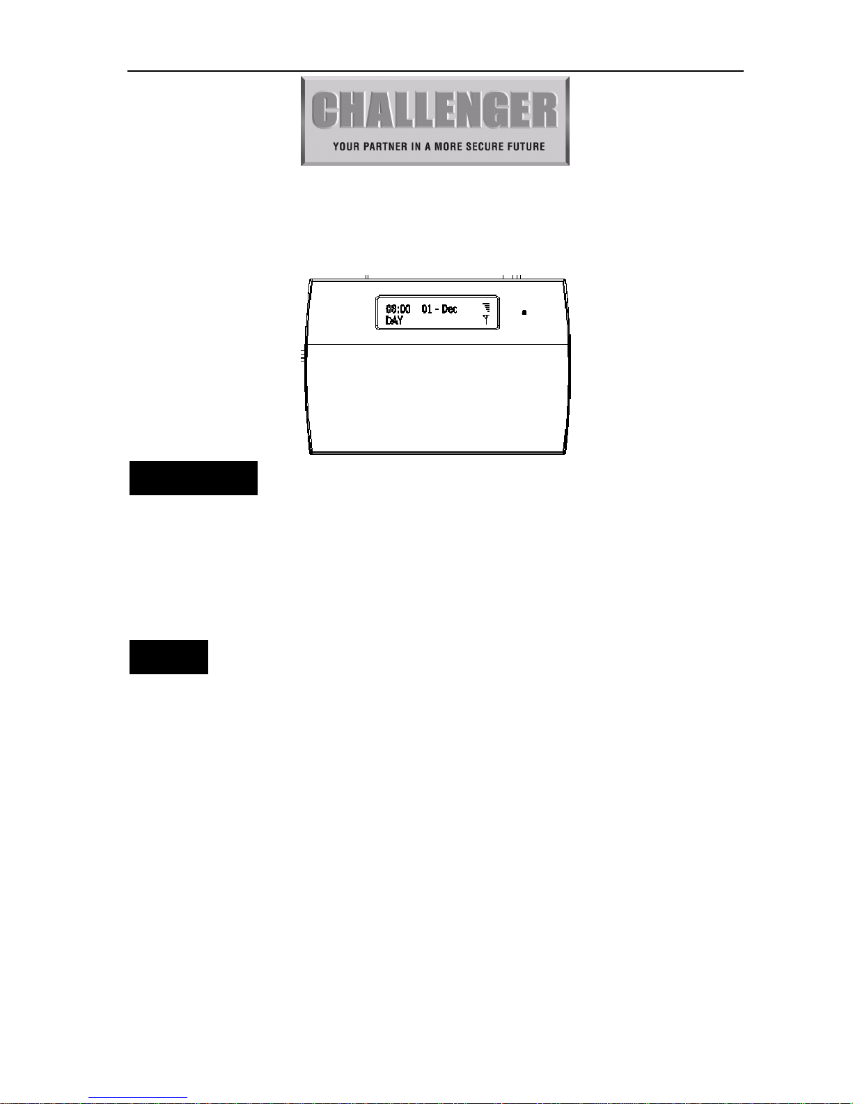
AT61 GSM Text Auto Dialer Manual
Introduction
AT61 GSM Text Auto Dialer is an advanced component that when triggered it will send a text
message up to 3 different telephone mobile numbers. If the AT61 dialer is connected to a Force10
intruder control panel then you have the additional feature to be able to ARM and DISARM via short
message text message on your mobile phone.
Compatible Networks: Vodafone, EE/Orange, O2
Feature
1. You can register a maximum three mobile numbers
2. one master code (default pin: 0123) to setup/program the dialer
3. Tamper protect function.
4. Modify pin
5. SMS COMMAND to set control panel going to Arm and disarm mode (Force 10 Panels only)
6. Eight terminals (five input for trigger as: Intruder, PA, ABORT, SET+ and Fire, two input for power
supply DC 13V + and DC 13V -, one output terminal PTS for to control ARM or DISARM for
control panel.
7. GSM receiving signal level indicated on LCD display.
Page 2
AT61 GSM Text Auto Dialer Manual
2
Challenger_AT61 _Instructions_Rev01
IMPORTANT NOTE: To enable the remote text function for Arm/Disarming and notification of Set/Unset with a
compatible Force10 Control Panel, then the below programming options will need to be configured from the Engineering
menu on the Force 10 control panel
1).Enable below features at Force-10 control panel
-[Setup system]->[Flag2]->[Key switch]->select “ON”
-[Setup system]->[Flag2]->[Strobe on set]->select “ON”
2).Once the GSM dialer (mobile phone is set) and is powered on, the preset mobile phone will receive below
message
SET off
FIRE Trigger
ABORT Trigger
PANIC Trigger
3).If “Tamper” or “Panic Alarm (PA) is triggered under “DAY” mode, the preset mobile phone will receive below
message
INTRUDER Trigger
4).All trigger of “Alarm”, “Tamper”, “Panic Alarm (PA)” under “SET” mode (armed status) will send message of
“INTRUDER Trigger”
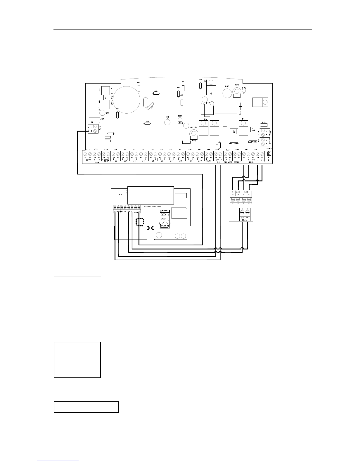
Wiring diagram
1). The supplied relay module will need to be used with security control panels without communicator outputs.
Below diagram illustrating connection to a
Force-10 control panel.
GSM Dialler
Force-10 Alarm Control Panel
External TF Board
Page 3
AT61 GSM Text Auto Dialer Manual
3
Challenger_AT61 _Instructions_Rev01
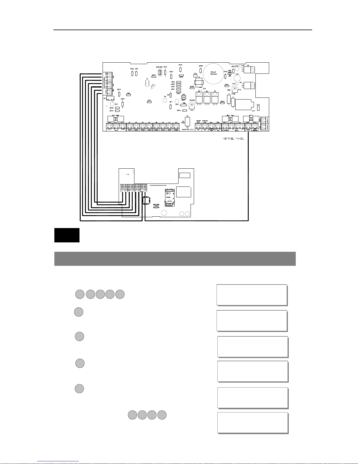
2). Connection with Force10 Main Panel with built-in communicators outputs
(AP10LEDC, AP11LEDC, AP11LCDC)
Usage
How to setup Force10 Control Panel ‘Key switch’ function
·Operate Control panel, setup key switch function
·Enter Manager program mode
Press
·Press key to require the Manage to authorize Engineer
access.
·Press to accept. It will give a 3hr window to operate
the Engineer operation mode.
·Press to accept, the accept tone will be generated.
·Press to go back DAY mode.
·Input 4-digit Engineer code and go to
MANAGER MENU
Authori
s
e Engr?
Engr Authorised
for 3 hours
MANAGER MENU
Set Chime Zones?
MANAGER MENU
Setup
Codes
?
00:26:15 08-Aug
DAY
LC ENGINEER MENU
Setup Programs?
P OR G
0 1 2 3
3
P OR G
P OR G
R ES TE
9 9 9 9
Page 4
AT61 GSM Text Auto Dialer Manual
4
Challenger_AT61 _Instructions_Rev01
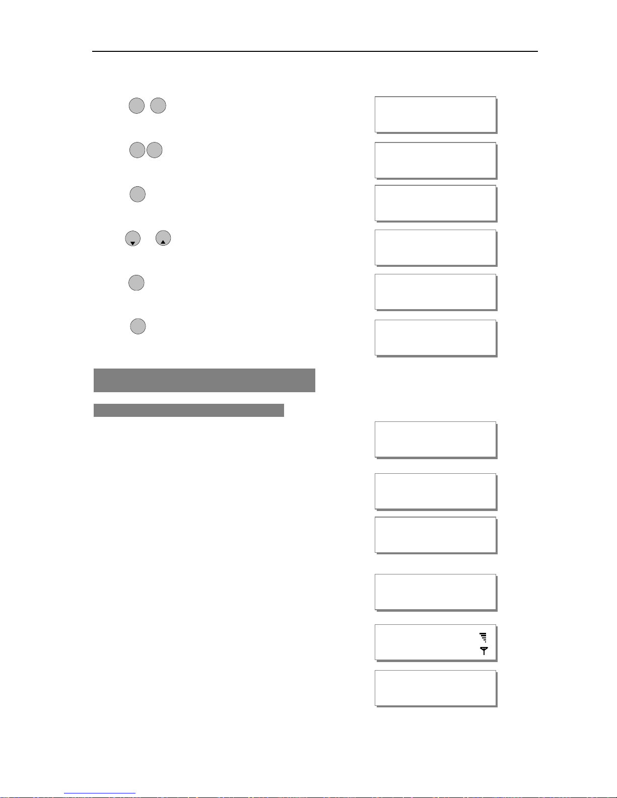
Engineer operation widow within 5 seconds.
·Press keys go into Setup System function.
·
Press keys go into Setup Flags 2
·Press key accept be selected flag.
·Press or key to toggle ON/OFF,
·Press to save.
·Press to go back DAY mode.
GSM Dialer Power on Message
NOTE: Insert Sim card before applying Power
·Display software version.
·Initial GSM module.
·For initial power will take approx 1minute to setup GSM module.
· When no SIM, display “SIM not inserted”
· GSM module has finished, normal display:
When
no SIM card inserted or incompatible network:
Init GSM Module
. . . . . . . . . . . . . .
Init GSM Module
.
SETUP SYSTEM
Flag
s 1?
SELECT FLAG 2
Key switch
?
P OR G
Key switch
OFF
P OR G
P OR G
5
Key switch
ON
O IM T
2
SELECT FLAG 2
PTS as Doorbel
l?
00:26:15 08-Aug
DAY
R ES TE
P OR G
LCD GSM DIALER
Version: V
3.91x
SIM not inserted
08:00 01-Dec
DAY
08:00 01-Dec
DAY X
Page 5

AT61 GSM Text Auto Dialer Manual
5
Challenger_AT61 _Instructions_Rev01
When the SIM card requires PIN, or poor signal quality:
Defaulting Panel to Factory Settings
You will change the value of all parameters to factory default.
CAUTION: All configurations of the panel are restored to factory default conditions.
To default to factory settings:
·Power down the GSM LCD Dialler.
·Press and hold keys.
·Power up.
·
Wait about 3 seconds, LCD display
“Reset NVM OK”
·
Release press keys and system initial GSM module.
How to Change USER CODE using self-user code
·System in Day mode
or system in SET mode.
·To enter User Menu
Press
· Input new code (4-digit)
·Press to save and return to Day mode.
If the 4-digits is the same as old, then display ‘Duplicate Code’
press any key return to Day mode and no change code.
Enter your code
*****
Enter new code
****
08:00 01-Dec
DAY
* * * *
P
OR G
P OR G
Duplicate Code!
08:00 01-Dec
DAY
9
Init GSM Module
.
R ES TE
Reset NVM OK
LCD GSM DIALER
Version: V
3.91x
08:00 01-Dec
08:00 01-Dec
DAY
Page 6

AT61 GSM Text Auto Dialer Manual
6
Challenger_AT61 _Instructions_Rev01
How to Set up the system
The full menu structure for the panel can only be accessed while in Master Program Mode. The structure is
shown in the following table:
How to go into Master Program Mode
·System work in Day mode
or system in SET mode.
·Go into Master Menu
Press
·Master Menu display.
1=Register Mobile
There are 3 Mobile Number can be created in the system,, all are 16-digit and can be set.
1 = Mobile Number 1, 2 = Mobile Number 2, 3 = Mobile Number 3
How to change Mobile number
Under Master Menu.
·Press keys go into Setup Codes function.
·
Press … or or key to select a Mobile Number
that you want to program.
Note: = mobile number 1, … = mobile number 3
MENU OPTIONS
1 Register mobile
2 Set up codes
3 View Event log
4 Set up system
Enter your code
*****
MASTER MENU
Register Mobile
?
P OR G
0 1 2 3
08:00 01-Dec
DAY
MASTER MENU
Register Mobile
?
P OR G
1
REGISTER MOBILE
Mobile Number 1?
3
1
1
3
O IM T
08:00 01-Dec
DAY
08:00 01-Dec
Page 7

AT61 GSM Text Auto Dialer Manual
7
Challenger_AT61 _Instructions_Rev01
·Press key to accept and go into set the mobile number.
Set new mobile number: 13686196127
Input new mobile number:
·Press to save. or Press key will without change the
mobile number and to go to modify next mobile number, if the
number is “Mobile Number 3”, it will leave “Register Mobile”
and go to next menu “Setup Codes”
·Press to return to master menu.
How to delete Mobile number
Under Master Menu.
·Press keys go into Setup Codes function.
·
Press … or or key to select a Mobile Number
that you want to set.
Note: = mobile number 1, … = mobile number 3
·Press key to accept and go into set the mobile number.
·Press key to clear the mobile number display.
·Press to accept delete the mobile number. or Press key
will without change the mobile number and to go to modify next
mobile number, if the number is “Mobile Number 3”, it will leave
“Register Mobile” and go to next menu “Setup Codes”
·Press to return to master menu.
2= Setup Codes
There are 4 user codes can be created in the system, all are 4-digit and can be set to any number from 0000 to
9999. The access codes ensure that only authorized users can operate the system.
SETUP MOBILE NUM
P OR G
SETUP MOBILE NUM
13686196127
1
3
6 8 6 1 9
1
P OR G
R ES TE
MASTER MENU
Setup Codes
?
R ES TE
REGISTER MOBILE
Mobile Number 3
MASTER MENU
Register Mobile
?
P OR G
SETUP MOBILE NUM
13686196127_
P OR G
1
REGISTER MOBILE
Mobile Number 1?
3
1
1
3
O IM T
SETUP MOBILE NUM
_
MASTER MENU
Setup Codes
?
R ES TE
O IM T
REGISTER MOBILE
Mobile Number 3
P OR G
R ES TE
6 7 2
Page 8

AT61 GSM Text Auto Dialer Manual
8
Challenger_AT61 _Instructions_Rev01
1 = user 1, 2 = user 2, 3 = user 3, 4 = master
User 1 – User 3 codes:
The user 1 to user 3 codes have the same operation for testing and Setting and Unsetting, changing their
own code.
Master code
To operate the alarm system you will need to use a code. A code is 4 digits long, and can be any
number from 0000 to 9999. By default master code is but you should change this
as soon as possible.
How to change User Code
This option allows each of the users to be given a code.
Under Master Menu.
·Press keys go into Setup Codes function.
·
Press … or or key to select a code
that you want to set.
Note: =user 1, … = user 3, … = master
·Press to accept and go into set the user.
·Press key to select Change Code function.
·Press key go into Change Code function.
·If no code programmed, then display
·Input new code (4-digit)
·Press to save. If the 4-digits is the same as old, then display
‘Duplicate Code’
press any key to leave, it goes to “Delete Code”
·Press key will without change the code and exit.
·Press key to return to master menu.
How to delete User Code
Under Master Menu.
·Press keys go into Setup Codes function.
MASTER MENU
Setup Codes
?
SELECT CODE
User 1?
P OR G
3
1
1
4
O IM T
P OR G
P OR G
USER CODE
****
USER CODE
.
. . .
P OR G
SETUP CODE
Delete Code
?
R ES TE
MASTER MENU
Setup Codes
?
P OR G
SETUP CODE
Change Code
?
0 1 2 3
R ES TE
R ES TE
4
1
2
Duplicate Code!
2
Page 9

AT61 GSM Text Auto Dialer Manual
9
Challenger_AT61 _Instructions_Rev01
·
Press … or or key to select a code
that you want to set.
Note: =user 1, … = user 3, … = master
·Press to accept and go into set the user.
·Press key to select Delete Code function.
·Press key will go into delete the user code function.
·Press key will delete the user code or press key to cannel
and go to modify next code.
·If the code is “Master codes”, it will leave
“Setup Codes” and go to next menu “View Event Log”.
Press to return to master menu.
3 = View Event Log
The event log gives displays of all the events that have taken place. The events are organised by date and time.
Up to 43 events can be stored in the memory. When the log reaches 43 events any new events will overwrite
the oldest events. The system is known as FILO (First In Last Out).
To view the event log:
Under Master Menu
·Press key to select View Event Log function.
·Press to accept and most recent event shown first.
·View older event log using or key.
·View newer event log using or key.
·View oldest event log using key.
·View newest event log using key.
Delete the Code?
Press PG for yes
MASTER MENU
View Event Log?
P OR G
2
SETUP CODE
Delet
e Code
?
MASTER MENU
View Event Log?
FIRE Trigger
08:12 05
-
Dec 43
P OR G
O IM T
PANIC Trigger
08:12 04
-
Dec 42
R ES TE
SELECT CODE
User 1?
3
1
1
4
O IM T
P OR G
4
2
FIRE Trigger
08:12 05
-
Dec 43
3
INTRUDER Trigger
08:08 01
-
Dec 01
1
FIRE Trigger
08:12 05
-
Dec 43
4
SELECT CODE
Master Code?
P OR G
R ES TE
3
Page 10

AT61 GSM Text Auto Dialer Manual
10
Challenger_AT61 _Instructions_Rev01
·
Press to select clear all alarm events.
·Press to accept.
·
or Press to cancel and go to next menu “Setup System”.
4 = How to Setup System
How to Setup Set Time
The time can be modified in hours, minutes in the format HH:MM. you must set it correctly, or else System
will generate an error tone and not save the changes.
Under Master Menu.
·Press keys go into Setup System function.
·Press to select Set Time function.
·Press to accept. Display current time.
set new time to 12:02
·Press number keys.
·Press to save it and clear second time, or press to
cancel, it will exit and go to “Set Date”.
How to Setup Set Date
The date can be changed in day, month, year format DD/MM/YY. The method of set date is the same as
how to set time.
e.g. Set current system date: 28-04-2017
Under Master Menu.
SETUP SYSTEM
Set Time
?
Set Time HH:MM
0
0:00
MASTER MENU
Set Date
?
Set Time HH:MM
12:02
P OR G
R ES TE
P OR G
0
4
2 2
R ES TE
MASTER MENU
S
etup System
?
P OR G
1
MASTER MENU
S
etup System
?
1
Clear Event Log
Press PG for yes
9
P OR G
MASTER MENU
Setup Syst
em?
Page 11

AT61 GSM Text Auto Dialer Manual
11
Challenger_AT61 _Instructions_Rev01
·Press keys go into Setup System function.
·Press to select Set Date function.
·Press to accept, display current date.
·Enter system date: Day/Mon/Year(6-digits)
·Press number keys.
·Press to save it, or press to cancel, it will exit
and go to “Reset NVM?”.
How to Restore to factor value using menu
You will change the value of all parameters to factory default value when you set it.
CAUTION: All configurations of the panel are restored to factory default conditions.
To default to factory settings:
Under Master Menu.
·Press keys go into Setup System function.
·Press to select Reset NVM function
·Press go into Reset NVM function.
·Press to accept and restore to factory setting value.
·Finished and return to next option.
How to Exit Master Program Menu
Under Master Menu.
·
Press key return to top of Master menu.
·
Press key to exit Master program mode,
return to Day mode, and two accept beep sound are heard
.
SETUP SYSTEM
Set Date
?
SETUP SYSTEM
Reset NVM
?
R ES TE
P OR G
Date: DD/MM/YY
28/04/17
R ES TE
MASTER MENU
Setup Codes
?
R ES TE
08:00 01-Dec
DAY
4
P OR G
P OR G
P OR G
SETUP SYSTEM
Reset NVM?
3
4
MASTER MENU
S
etup System
?
P OR G
Reset NVM
Press PG for yes
MASTER MENU
Register Mobile?
2
P OR G
Date: DD/MM/YY
25/04/17
0
248
1 7
Page 12

AT61 GSM Text Auto Dialer Manual
12
Challenger_AT61 _Instructions_Rev01
How to ARM or DISARM Mode
Note: Make sure the Force10 Control Panel Key switch function is ON.
ARM mode, send a SMS text message to the AT61 dialer telephone number as following (case insensitive):
User pin code (4-digital) + ARM (arm)
e.g. 0123 ARM
DISARM mode, send a SMS text message to the AT61 dialer telephone number as following (case
insensitive):
User pin code (4-digital) + DISARM (disarm)
e.g. 0123 disarm
GSM send SMS format to mobile as following:
Action event SMS content Note
ARM action* Mobile number + ‘release on’ Mobile number Sent SMS
‘ ARM’ command.
DISARM action* Mobile number + ‘release off’ Mobile number Sent SMS
‘ DISARM’ command.
FIRE input FIRE trigger
PA input PANIC trigger
INT input INTRUDER trigger
SET high level input* SET On
SET low level input* SET Off
ABORT input ABORT trigger
* available for control panel without communicators
Due to our policy of continuous improvement we reserve the right to change specification without prior notice.
Errors and omissions accepted. These instructions have been carefully checked prior to
publication. However, no responsibility can be accepted by Challenger Security Products for any
misinterpretation of these instructions.
Distributed by:
CHALLENGER SECURITY PRODUCTS
10 SANDERSONS WAY, BLACKPOOL, FY4 4NB
Email: enquiries@challenger.co.uk
Website: www.challenger.co.uk
 Loading...