

Page 1
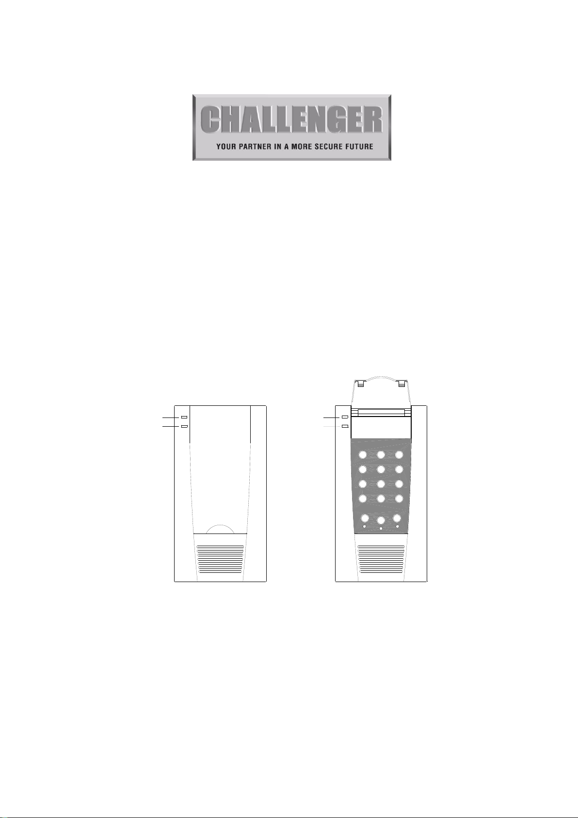
Power on LED
MIC
MIC
Power on LED
321
5 64
7
98
STORE
0
REC/PLAY
M3
M2
M1
AT60
AUTO DIALLER
User Guide
Page 2

AT60 User Guide
Table of Contents
I. Overview 3
II. Installation 4
III. Initialize the Dialer 5
IV. Using the Dialer 6
V. Maintenance 6
VI. Specifications 7
VII. Customer Information 7
Annex 1 – AT60 Auto Voice Dialer Wire Connection Diagram
Annex 2 – AT60 Auto Voice Dialer Operation Summary
Annex 3 – AT60 Wiring Connection between AT60 and Alarm Panel
Page 2
CHALLENGER_AT60_Instructions_Rev02
Page 3

AT60 User Guide
I. Overview
AT60 Auto Voice Dialer is a microprocessor based security monitoring device
which can notify you of an alarm event through public telephone system. The
device normally works with a control panel of any standard alarm system.
IMPORTANT - Please read through the whole manual OR Section I of User
Guide, Wire Connection Diagram (Annex 1) and Operation Summary (Annex
2) before commencing installation and operation.
I.1 Components
The main unit is the AT60 Auto Voice Dialer.
In addition, the standard dialer set also includes the following connecting
accessories:
(a) A length of telephone cord with plug.
You may need to purchase the following parts, which are not included in the
standard dialer set, to complete the installation:
(a) A 9V alkaline battery for backup power.
(b) Connections to a suitable approved 12V DC power supply or alarm control
panel.
I.2 Tools may be needed
For installation, the following tools are required:
Screwdrivers
Hammer
Power drill
Wire cutter and wire stripper
Eye protection glasses etc.
I.3 System features
Ease of Installation - You can quickly connect the dialer to a telephone
line, alarm system or 12v DC power supply. The dialer required to be wall
mounted.
Simple to Use - You may use a single function key to do the functions
such as record message, play back message, start and exit a phone number
entry.
Clear Message - A digital voice chip is used to ensure the clearest
possible recording of your pre-stored message. The message can be
played back so that you can check whether the contents are accurate. The
recorded message will not be lost even if the power to the dialer has been
cut off.
Connectivity - The dialer can be connected to different types of alarm
systems.
Page 3
CHALLENGER_AT60_Instructions_Rev02
Page 4
AT60 User Guide
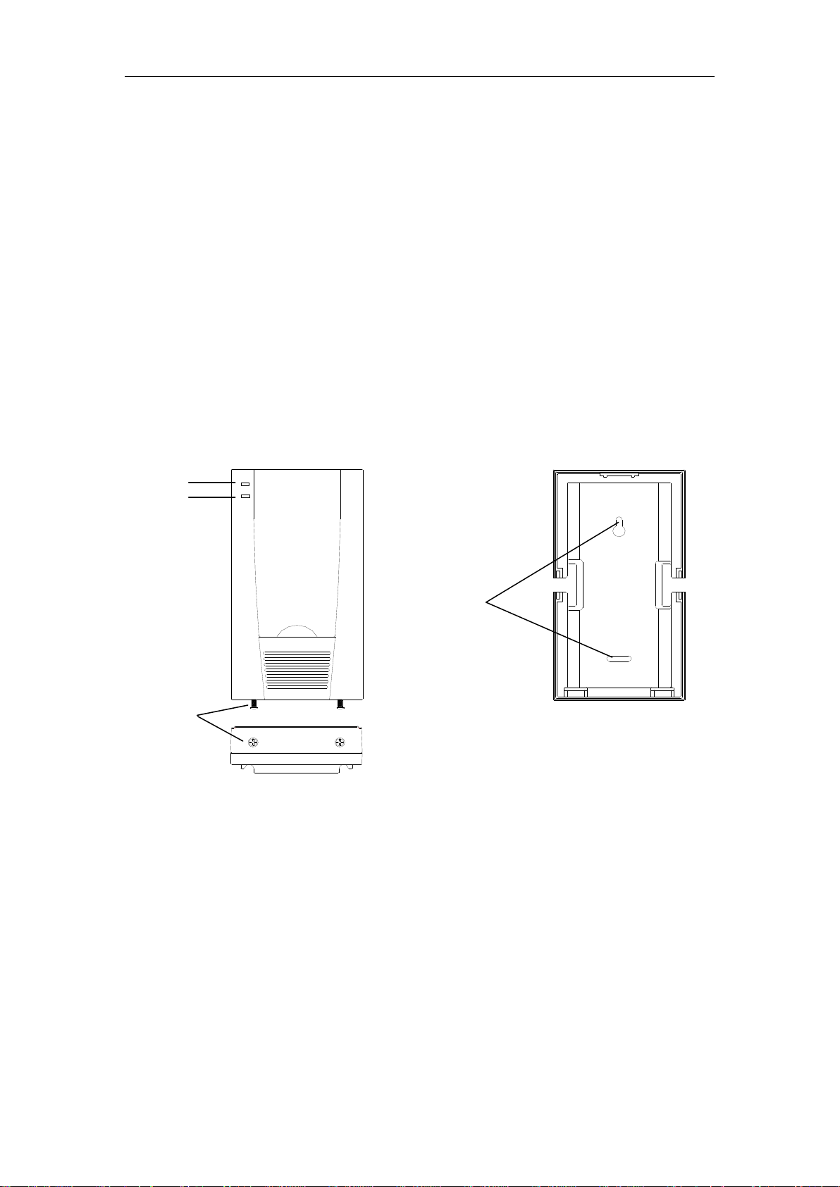
Mounting
holes
(back cover of Dialer)
Figure 2
Screw
(Bottom View)
Figure 1
Power LED
Microphone
Three Pre-stored Phone Numbers - You may store up to 3 phone
numbers in the dialer. It is more likely that your message will get through
to someone who can take necessary action. When an alarm event happens,
the stored phone numbers will be dialed out in sequence up to five times
each or until any call receiver acknowledges and stops it through the line.
II. Installation
II.1 Location
Select a location for the dialer
Near the alarm system
Near a phone socket
To be installed with the protected area and not easily accessible to
intruders
II.2 Fitting the Dialer
WARNING: Isolate the supply before starting work.
a. Remove and retain the two screws from the Main Console (Figure 1).
b. Position the back cover of the Main Console against the wall. Mark and drill two
5 mm mounting holes as shown (Figure 2) and use two 16 mm dome head screws
and wall plugs to mount the unit on your chosen location.
c. Connect the DC supply (Figure 3).
d. Connect the phone cord provided (Figure 3).
e. If there is broadband connected to the same phone line please ensure an ASDL
filter is fitted to the dialer.
f. Connect the alarm terminal to your alarm system (Figure 3).
Page 4
CHALLENGER_AT60_Instructions_Rev02
Page 5

AT60 User Guide
21 3
5
64
7
98
STOREREC/PLAY
0
M2
M1
M3
9V alkaline battery
Dialer keypad
(Back View of Dialer, with
the back cover taken out)
Figure 3
TEL
_
12V
+
_
SET
+
Connect to the
telephone
line/cord
Connect to
12vDC supply
Connect to your alarm
panel
SET + connects to
alarm panel bell trigger
(SET + & - can also be
triggered by volt free contacts)
III. Apply Power to the AT60 Dialer
g. Plug in a 9V alkaline backup battery to the battery lead (Figure 3).
h. Replace and screw the Main Console to the back cover.
i. Plug the AC Adapter to the Main Power Outlet.
To prepare the dialer, perform the following procedures:
III.1 Store Phone numbers
a. Press REC/PLAY key twice.
b. Enter first phone number.
c. Press STORE key twice.
d. Press M1 key.
e. Press REC/PLAY key once.
f. Repeat steps ‘a’ to ‘e’ for 2nd phone number (Press M2 in step ‘d’).
g. Repeat steps ‘a’ to ‘e’ for 3rd phone number (Press M3 in step ‘d’).
Note: A pause cannot be stored when entering the telephone number and is not
compatible with PABX systems.
III.2 Check Phone numbers
a. Press REC/PLAY key twice.
b. Press M1 key.
c. A DTMF tone of the stored phone number will be played back.
d. Repeat steps ‘a’ to ‘c’, pressing M2 or M3 in step ‘b’ to check the 2nd or 3rd
phone numbers.
Page 5
CHALLENGER_AT60_Instructions_Rev02
Page 6

AT60 User Guide
III.3 Record the voice message
a. Press the REC/PLAY key for 2 seconds (until M1 LED will be on).
b. Speak the message clearly to the microphone while the REC/PLAY key is still
being pressed.
c. Release the REC/PLAY key when your voice message recording is completed
(M1 LED will turn off).
III.4 Listening the message.
Press REC/PLAY key once, then the voice message will be played back.
III.5 Testing the Dialer
NOTE: Make sure who receives your dialer message knows that you are testing
the equipment. Call each of the phone numbers that the dialer will dial and brief
them how to handle the call before testing. DO NOT store any of the Emergency
phone numbers (such as Fire station, Police) into the dialer.
a. Insert the phone cord from dialer into the phone jack. It is recommended to use
the direct phone line for the dialer. If there is broadband connected to the same
phone line please ensure an ASDL filter is fitted to the dialer.
b. Trigger the alarm system.
c. The dialer dials the first stored phone number, if the call is answered, the dialer
will play the voice message 3 times. The called receiver may
stop/acknowledge the playback by pressing any of the number keys on the
phone receiver twice and hang up. This acknowledges the alarm call and stops
the dialer.
d. If the phone number is busy, the dialer hangs up and tries the next stored phone
number in sequence.
e. If there is no answer the dialer hangs up after 6 rings and tries the next stored
phone number in sequence.
f. If there is no acknowledgment (pressing any of the number keys on the
receiver phone twice) from the call receiver, the dialer hangs up and tries the
next stored phone number in sequence.
g. If the acknowledgement has been received, the dialing sequence will be exited
and the dialer stops. Otherwise, the dialer will continue the dialing sequence
until each stored phone number has been dialed 5 times.
IV. Using the Dialer
When the dialer is connected to an alarm system and is triggered by an alarm event,
the dialer will automatically dial the stored phone numbers and play the
pre-recorded message.
Page 6
CHALLENGER_AT60_Instructions_Rev02
Page 7

AT60 User Guide
V. Maintenance
Once every year,
★ Replace the alkaline battery in the Dialer.
★ Test Monthly for correct operation
Additionally,
★ In case of main power lost over 24 hours, replace the alkaline battery in the
Dialer (as that the telephone numbers will be erased).
VI. Specifications
Type Microprocessor based automatic voice dialer
Housing ABS
Pre-stored numbers 3 sets of phone numbers (programmable). Each phone number
has 16 digits capacity
Dialing mode Tone
Pre-stored Message 20 seconds (programmable)
Trigger type Switch negative to SET + terminal or Dry contact (NO)
Power Supply 12V dc
Backup battery 9V size alkaline battery
Power Consumption 0.1W (Standby)
VII. Customer Information
The dialer MUST NOT be connected to
Coin-operated systems
Party-line systems
Digital phone systems (PABX telephone system)
Page 7
CHALLENGER_AT60_Instructions_Rev02
Page 8

9V alkaline battery
TEL
+ _ +
_
Connect the
telephone line/cord
(NOTE 1)
Connect to the
AC/DC Adaptor
line/cord
Connect to your
alarm panel (Accept
dry contact signal)
SET + connects to
alarm panel bell
trigger
12V
SET
(Back view of dialer, with
the back cover taken out)
AT60 User Guide
AT60 Auto Voice Dialer Wire Connection Diagram
NOTE 1: The dialer should not be connected to coin-operated telephone systems, party-line system nor digfital
telephone systems (PABX). It is recommended to use a direct phone line for the dialer.
Page 8
CHALLENGER_AT60_Instructions_Rev02
Page 9

AT60 User Guide
M1M2M3
1 2 3
4 5
6
9
7
8
REC/PLAY
0
STORE
after pressing for 2 sec.
8
7
9
REC/PLAY
0
STORE
4 5
6
21 3
M1M2M3
‘M1’ LED lights up
‘M1’ LED lights off
(DTMF tone of stored phone
number played back)
Green LED
}
Microphone
Dialer keypad
LED
REC/PLAY
REC/PLAY
M1
M1
REC/PLAY
REC/PLAY
2 2 3 4 8
Phone No.
(Example phone number is 22348)
STORE
STORE
M1
REC/PLAY
REC/PLAY
REC/PLAY
M1
ANNEX 2
AT60 Auto Voice Dialer Operation Summary
A) Record message
Press
( Keep on pressing )
(Speak your message clearly to the microphone and release
the key when your voice message is completed).
B) Play message
Press (Play the recorded message)
C1) Store phone number
Press Press
Press Press Press Press
C2) Check to ensure phone number has been stored
Press Press Press
Repeat Procedures C1 and C2 to store and check the 2
nd
and 3rd priority phone numbers.
Page 9
CHALLENGER_AT60_Instructions_Rev02
Page 10

AT60 User Guide
ANNEX 2
(Instead of pressing M1 in the repeated Procedures C1 and C2, Press M2 for 2nd and M3 for 3rd
priority phone number)
D) Alarm trigger
When the dialer is triggered, the first priority phone number M1 will be dialed out.
If the line cannot go through the first priority phone number M1, the next stored phone
numbers (2nd, 3rd priority phone numbers, M2 & M3) will be dialed out.
When the telephone call is answered, the recorded message will be played back three times or
until call receiver responses by pressing any of the number keys 0~9 twice on the receiver
phone (acknowledgment) to stop the playback and hangs up to exit the dialing
sequence.
If there is no response from any of the three stored phone numbers, the dialing cycle will start
again and continue five times or until one of the phone numbers is answered.
E) Hang up and Exit the Dialing Sequence
After taking up the call and listening to the recorded message, the call receiver can press any of
the number keys on his telephone two times and hang up. This acknowledges the call, stops the
playback of the recorded message and gets the dialer to exit the dialing sequence.
NOTE: WHEN STORING PHONE NUMBERS AND (OR) MAKING TEST CALLS TO THE
STORED PHONE NUMBERS
1. Remain on the line and briefly explain to the call receiver the reason for the call.
2. Perform such activities in the off-peak hours, such as early morning or late evenings.
Page 10
CHALLENGER_AT60_Instructions_Rev02
Page 11

AT60 User Guide
Terminals
Connector
Wiring Connection between AT60 and Force 10 Alarm Panel
AT60 and the Tamper Output Terminals
ANNEX 3
The AT60 comes with the tamper output terminals which is a dry contact output.
Plug in the connector and fit the terminals inside the AT60
Connect the cable from Tamper Switch terminals to Alarm Panel
Page 11
CHALLENGER_AT60_Instructions_Rev02
Page 12

AT60 User Guide
Due to our policy of continuous improvement we reserve the right to change specification without
prior notice. Errors and omissions accepted. These instructions have been carefully checked
prior to publication. However, no responsibility can be accepted by Challenger Security Products
for any misinterpretation of these instructions.
Distributed by:
CHALLENGER SECURITY PRODUCTS
10 SANDERSONS WAY, BLACKPOOL, FY4 4NB
Email: enquiries@challenger.co.uk
Website: www.challenger.co.uk
Page 12
CHALLENGER_AT60_Instructions_Rev02
 Loading...