

Page 1
Challenger_ASFP1_Instructions_Rev01
ASFP1
MOTION DETECTOR
The Motion Detector is designed with two detecting sensors, Passive Infra-Red
(PIR) sensor and light sensor, in order to fulfill the purpose of security and home
automation. When the detector is cooperated with security appliances, it is acting
as a security device by detecting changes in infra-red radiation levels. If a person
moves within or across the device field of vision, a trigger radio signal will be
transmitted to cause full alarm condition. Alternatively, when the detector is
worked with home automation appliances, the detector can be set to perform the
role of home automation device by detecting both changes in infra-red radiation
levels and percentage of lux levels. Once night falls, the percentage of ambient
illumination is lower than preset value. If a person moves within or across the device
field of vision, a trigger radio signal will be transmitted so as to turn on the
connected lightings for better illumination.
The PIR Detector requires a CR123A 3.0V Lithium battery which under normal
conditions will have typical life in excess of 1 year. When the battery level drops to
an unacceptable level, the LED behind the detection window will flash once every
30 seconds. When this occurs the batteries should be replaced as soon as possible.
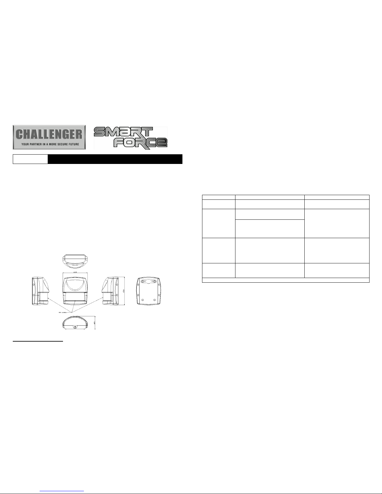
Product Overview
IMPORTANT NOTE:
The motion detector supplied in the kit HAS already been
learnt to the Gateway Hub and does not require learning to the ASFK1 Gateway
Hub. For replacement or additional PIR’s these will need to be learnt to the
Gateway Hub before installation.
LEARNING MOTION DETECTOR
Please refer to Smart Force Quick Set Up Guide. The easiest way to learn the
device is either via through the Smart Force Web Site or Smart Force App once you
have completed the System Registration.
On the back of the PIR PCB there is a tamer switch, this is also used to carry out
learning to the Gateway Hub and reset. When the detector is first powered up,
the LED flashes on and off alternately and repeatedly at 2-second intervals. This is
to indicate that device has not been assigned to the Gateway Hub and will not
work.
Put the Gateway Hub in to learn mode via the Smart Force Web User Interface or
Smart Force App. Then select add a device.
Function
Descriptio
n Indication
Device Not
Learnt
The Gateway Hub has not
allocated or Learnt the PIR
2-second on, 2-second off for 2
minutes.
Learn Mode 1. Gateway Hub entered learn
mode
1. Waiting to Learn, LED ON
0.5 second, OFF 0.5 second
2. Success, the green LED will
be bright for 0.5 second.
3. Fail, the green LED will flash
3 times.
2. Pressing tamper switch 3 times
within 1.5 second and release
in 6 seconds, the PIR will enter
learn mode.
Reset 1. In the 30-second learn mode,
press the tamper switch for
6~10 seconds, this will delete
the device from Gateway Hub.
1. Press the Tamer Switch for 6
seconds, the LED will light
be constant.
2. Fail, the green LED will flash
3 times.
Empty ID code 1. IDs are excluded and all of
preset value will be reset to
factory default.
1. The orange light will
2-second on, 2-second off
Failed or success learning can be viewed from the Gateway Hub website or App.
Choosing a Mounting Location
Please ensure the motion sensor is within signal range of the Gateway Hub prior to
mounting.
The PIR Detector is suitable for mounting in dry interior locations only.
The recommended position for a PIR Detector is in the corner of a room mounted at
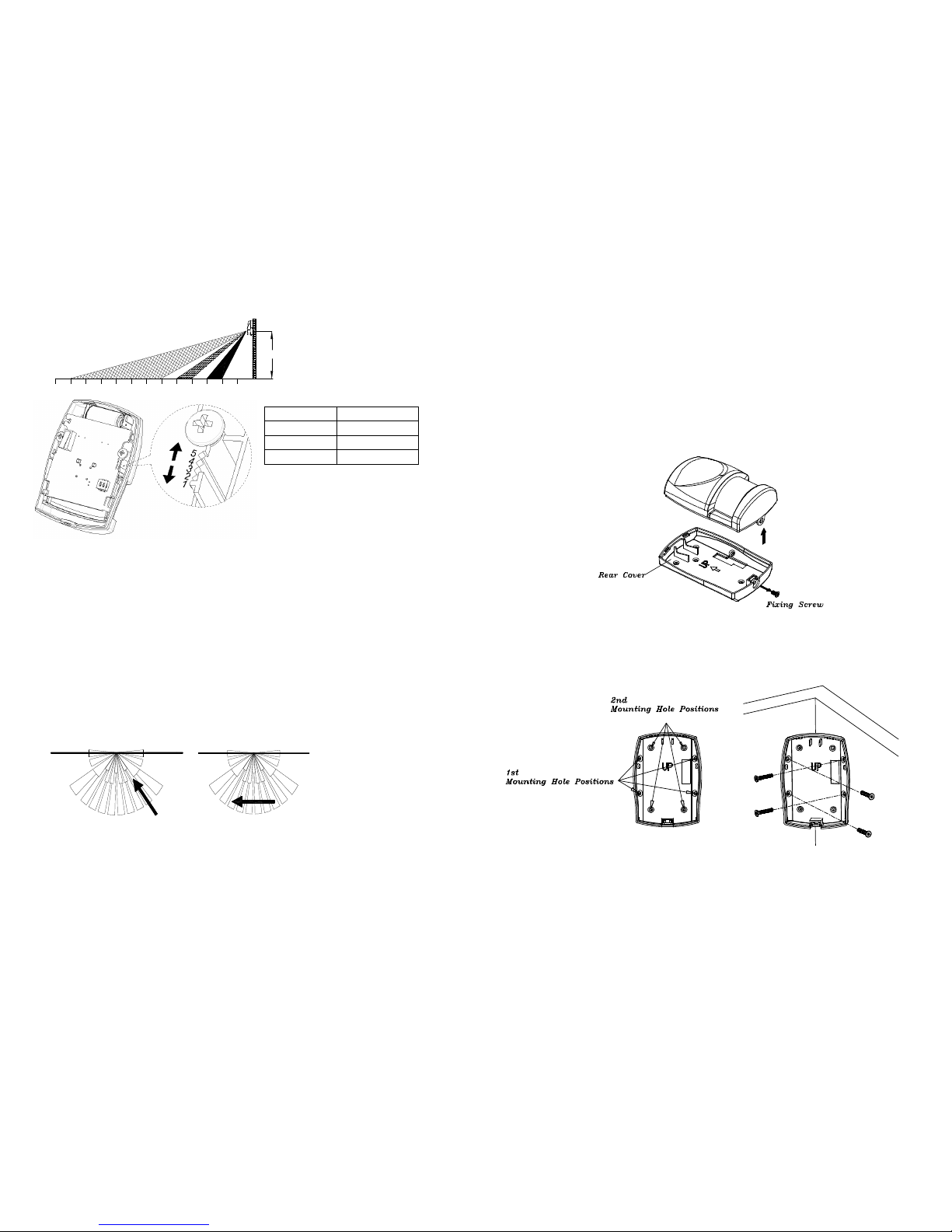
a height between 1.8 and 2m. At this height, the PIR detector will have a maximum
range of up to 9m with a field of view of 110°, subject to the position for the PCB
being set in 5. (FIGURE 1& 2) The position of the PCB inside the PIR can be set to
5 different positions to adjust the range of the detector. Setting the PCB in position 3
will reduce the range to 6m approximately, with position 1 providing a range of 3m
approximately. The recommended position setting for the PCB is in position 5.
Page 2
Challenger_ASFP1_Instructions_Rev01
PCB Position Range
1 3m
3 6m
5 9m
FIGURE 1 & 2
When considering and deciding upon the mounting position for the detector the
following points should be considered to ensure trouble free operation:
1. Do not locate the detector facing a window or where it is exposed to or facing
direct sunlight. PIR Detectors are not suitable for use in conservatories.
2. Do not locate the detector where it is exposed to extractor fans.
3. Do not locate the detector directly above a heat source, (e.g. fire, radiator, boiler,
etc).
4. Where possible, mount the detector in the corner of the room so that the logical
path of an intruder would cut across the fan detection pattern. PIR detectors
respond more effectively to movement across the device than to movement
directly towards it (FIGURE 3).
Less Sensitive More Sensitive
FIGURE 3
5. Do not locate the detector in a position where it is subject to excessive vibration.
6. Ensure that the position selected for the PIR detector is within effective range of
the system (refer to System Installation and Operating Manual).
Note: When the system is armed, household pets should not be allowed into an
area protected by a PIR detector as their movement would trigger the PIR and
generate an alarm.
Installation
Ensure that the system is in Test Mode.
1. Undo and remove the fixing screw from the bottom edge of the detector.
Carefully pull the bottom edge of the detector away from the rear cover and
then slide down to release the top clips (FIGURE 2).
FIGURE 2
2. Carefully drill out the required mounting holes in the rear cover using 3mm drill
according to whether the unit is being mounted in a corner or against a flat wall.
Note: Using the first mounting hole to fulfill corner mounting installation, while
2nd mounting hole for flat wall installation (FIGURE 3a & 3b).
3. Using the rear cover as a template, mark the positions of the fixing holes on the
wall.
1
23456789101112013
2M
FIGURE 3a
Corner mounting
FIGURE 3b
Page 3

Challenger_ASFP1_Instructions_Rev01
4. Fix the rear cover to the wall using the two 18mm No.4 screws and 25mm wall
plugs (a 5mm hole will be required for the wall plugs). Do not over-tighten the
fixing screws as this may distort or damage the cover.
5. Configure the detector as described below. Remember that on initial installation
that the device needs to be tested.
6. Check that the detector PCB is located and set in the correct position to provide
the required detection range. To adjust the PCB position, simply slide it up or
down ensuring that the location legs are aligned with the required position
number marked on the board.
7. To refit the detector to the rear cover and locate the clips in the top edge into the
rear cover. Push the lower edge of the detector into place and refit the fixing
screw in the bottom edge of the detector to secure in position. Do not
over-tighten the fixing screws as this may damage the casing.
Settings
Warm-Up
It will take approximately 2 minutes to warm up after battery has been connected.
When the red LED turns on steadily for 5 seconds, it implies warm-up procedure is
completed and the detector is ready for detection.
Operation Wall Mounting
1. After power on, PIR will warm-up for about 2 minutes, if the unit is not learnt
then the LED will continuously blink to notify the user. Range or Distance test
for PIR can only be done after the sensor has been learnt so NO NOT fit the
PIR until learnt with the Gateway Hub.
2. Test mode:
After Learnt, if Tamper switch is not pressed, the unit will enter test mode. When
PIR is triggered, the red LED will light up once and retrigger time is about 5 sec.
However, if Tamper switch is pressed, the unit will enter normal mode. When
PIR is triggered, the red LED will not light up and retrigger time is based on set
up value.
3. By walking into a protected area within coverage of 110 degrees, the detector
will now be triggered each time the detector senses movement. The associated
appliances will be activated. For example, siren will be sounded or indication of
movement detection will be shown on the controller. It implies that the unit is
working properly.
Troubleshooting
Symptom
Possible Cause
Recommendation
LED cannot be displayed Run out of battery power Replace a new battery
Check if reverse battery
polarity
Refit the battery with correct
polarity
The detector not working Check if mounting location
is proper
Reposition its mounting
location
Remove the source of
interference
Check if the detector is out
of order
Do not open the detector;
send it to the local retailer.
Two minutes warm up is
completed, The detector
does not work and LED
flashes on & off repeatedly at
2-second intervals
Check if detector is first
power up or the detector
has executed exclusion or
reset procedure
Please carry out inclusion
procedure; make sure there
are ID codes stored in the
detector.
Specifications
Battery CR123A 3.0V 1700mAh Lithium Battery
Operating Range 30m line of sight
Warm Up Time About 2 minutes
PIR Detection Coverage
Wall-
Mounted:
Up to 10m x 110° (at 1.8m mounting height & 25°C)
Operating Frequency 868.42 MHz (EU)
ZDK Version V5.02
Due to our policy of continuous improvement we reserve the right to change specification
without prior notice.
Errors and omissions excepted. These instructions have been carefully checked prior to
publication. However, no responsibility can be accepted by Challenger for any
misinterpretation of these instructions.
Challenger Security Products
10 Sandersons Way, Blackpool, FY4 4NB
Tel: 01253 791888, Fax: 01253 791887
Email: enquiries.challenger@adivision.co.uk
Web: www.challenger.co.uk
 Loading...