

Page 1
APFWKGSM GSM Wireless Alarm Operating Manual
APFWKGSM Manual Rev01
- 1 -
POWER
APFWKGSM – GSM WIRELESS ALARM
OPERATING Manual
SAFETY
Before proceeding with the installation, please note the following safety warnings:
DO NOT connect the mains supply directly to the products, this will cause permanent damage to
the products.
Control panel is for indoor use only. Avoid mounting location which can expose this product to splashing or
dripping liquid.
Always follow the manufacturer’s advice when using any tools power tools, ladder/steps,. using steps or
ladders, and wear suitable protective equipment (e.g. safety goggles) when drilling holes, etc. The use of ear
protectors are advisable when working in close proximity to the Control Panel’s Siren when the front panel
cover is removed due to the high sound level produced. Before drilling holes in walls, check for hidden
electricity cables and water pipes. The use of a cable/pipe locator is advisable if in doubt. Batteries (battery
pack or batteries installed) should not be exposed to excessive heat. Danger of damage to the unit may occur
if battery is incorrectly replaced. Replace only with the same or equivalent type. (Do not mix batteries type).
IMPORTANT – Please read this manual carefully, in full, before commencing
Installation. You will find installation easier if you follow these steps in the
sequence shown.
Page 2

APFWKGSM GSM Wireless Alarm Operating Manual
APFWKGSM Manual Rev01
- 2 -
Table of Contents
SECTION 1 – OVERVIEW OF SYSTEM .......................................................... - 5 -
1.1 – System Feature............................................................................................................................. - 5 -
1.2 – Contents .......................................................................................................................................... - 5 -
1.3 – Tools Required .............................................................................................................................. - 6 -
1.4 – Explanation of Terms ................................................................................................................. - 6 -
SECTION 2 – INSTALLING YOUR SYSTEM .................................................. - 6 -
2.1 – Location of components ............................................................................................................ - 6 -
2.2 – Fixing the Control Panel ............................................................................................................ - 8 -
2.3 – PCB .................................................................................................................................................... - 9 -
2.4 – How to inset your SIM Card ..................................................................................................... - 9 -
2.5 – Extension speaker ..................................................................................................................... - 10 -
SECTION 3 – FACTORY DEFAULT SETTING .............................................. - 10 -
SECTION 4 – MAINS CONNECTION ........................................................... - 11 -
SECTION 5 – FIRST POWER UP .................................................................. - 12 -
SECTION 6 – HOW TO SET UP THE SYSTEM ............................................. - 13 -
6.1 – Set Mobile Number .................................................................................................................... - 13 -
6.1.1 – Entering Master Program Mode ............................................................................................ - 13 -
6.1.2 – Setting the Mobile Phone Number ........................................................................................ - 13 -
6.1.3 – Setting the Mobile Phone Name ............................................................................................ - 14 -
6.1.4 – Deleting the Mobile Phone Number ...................................................................................... - 15 -
6.2 – Setup Programs .......................................................................................................................... - 15 -
6.2.1 – Full mode Setting .................................................................................................................... - 15 -
6.2.2 – Part mode Setting ................................................................................................................... - 16 -
6.2.3 – Setting zone function .............................................................................................................. - 16 -
6.2.4 – Setting Delay Time function .................................................................................................. - 17 -
6.3 – Setup Zones Name .................................................................................................................... - 17 -
Page 3

APFWKGSM GSM Wireless Alarm Operating Manual
APFWKGSM Manual Rev01
- 3 -
6.3.1 – Setting Zone Name ................................................................................................................. - 17 -
6. 4 – Change Code .............................................................................................................................. - 18 -
6. 4.1 – Changing Master Code .......................................................................................................... - 18 -
6. 5 – Setup system .............................................................................................................................. - 19 -
6.5.1 – Entering Bell Time ................................................................................................................... - 19 -
6.5.2 – How to Set Time ...................................................................................................................... - 19 -
6.5.3 – Entering Set Date .................................................................................................................... - 20 -
6.5.4 – Setting GSM Signal Level Display .......................................................................................... - 21 -
6.5.5 – Restoring to factory setting using menu.............................................................................. - 21 -
6. 6 – View Event Log .......................................................................................................................... - 21 -
6.7 – Test System ................................................................................................................................. - 22 -
6.7.1 – How to Test Speaker .............................................................................................................. - 22 -
6.7.2 – How to perform Walk Test ..................................................................................................... - 23 -
6.7.3 – How to perform SMS test set ................................................................................................ - 23 -
6.8 – Setup Wireless Device ............................................................................................................. - 24 -
6.8.1 – How to pair wireless remote key .......................................................................................... - 24 -
6.8.2 – How to delete all wireless remote keys ............................................................................... - 25 -
6.8.3 – How to learn a wireless zone ................................................................................................ - 25 -
6.8.4 – How to delete a wireless zone .............................................................................................. - 26 -
6.8.5 – How to delete all wireless zones ........................................................................................... - 26 -
6.9 – How to Exit Master Program Menu ..................................................................................... - 26 -
SECTION 7 – USING SYSTEM ...................................................................... - 27 -
7.1 – Setting the System .................................................................................................................... - 27 -
7.1.1 – Using the keyboard on control panel to setup .................................................................... - 27 -
7.1.2 – How to use SMS to set the system ....................................................................................... - 28 -
7.1.3 – Disarming the System ............................................................................................................ - 28 -
7.1.4 – How to use SMS to reset the system ................................................................................... - 28 -
7.1.5 – How to DISARM the Alarm and RESET the system ............................................................ - 29 -
7.1.6 – How to use Panic Alarm on keypad ...................................................................................... - 29 -
7.1.7 – How to use Panic Alarm on wireless key ............................................................................. - 29 -
7.1.8 – SMS Content of feedback for system action ....................................................................... - 30 -
SECTION 8 – MAINTENANCE ...................................................................... - 30 -
SECTION 9 – TROUBLESHOOTING GUIDE ................................................ - 30 -
SECTION 10 – SPECIFICATIONS ................................................................ - 32 -
Page 4

APFWKGSM GSM Wireless Alarm Operating Manual
APFWKGSM Manual Rev01
- 4 -
APPENDIX 1 – EVENT LOG MESSAGES ...................................................... - 34 -
APPENDIX 2 – ZONE - LOCATION TABLE .................................................. - 35 -
DISPOSAL AND RECYCLING........................................................................ - 35 -
Page 5
APFWKGSM GSM Wireless Alarm Operating Manual
APFWKGSM Manual Rev01
- 5 -
POWER
Section 1 – Overview of System
This brilliant system incorporates a quad band GSM module to notify you by phone and SMS when
the alarm is triggered.
The system is easy to set up and to operate, utilising wireless PIR detectors and reed switches, so
there's virtually no wiring at all. Fully featured with up to ten zones, remote arm and disarm function
and battery backup. This system allows you to cater for all your security needs in one system while
giving you peace of mind. Supplied with the alarm control unit, loud 120dB siren, a wireless PIR
detector and wireless reed switch and two wireless remote controls.
1.1 – System Feature
• 10 wireless zones.
• Maximum 4 wireless remote key.
• 10 Zones programmable for Delay zone or Immediate zone.
• Output for External Siren.
• 1 Full set and 1 fully selectable part set programs.
• 100 events memory for event log.
• Programmable timers for exit/entry and bell cut off
• Walk Test mode
• Quick set system
• Non-volatile memory for protection of master program and event log.
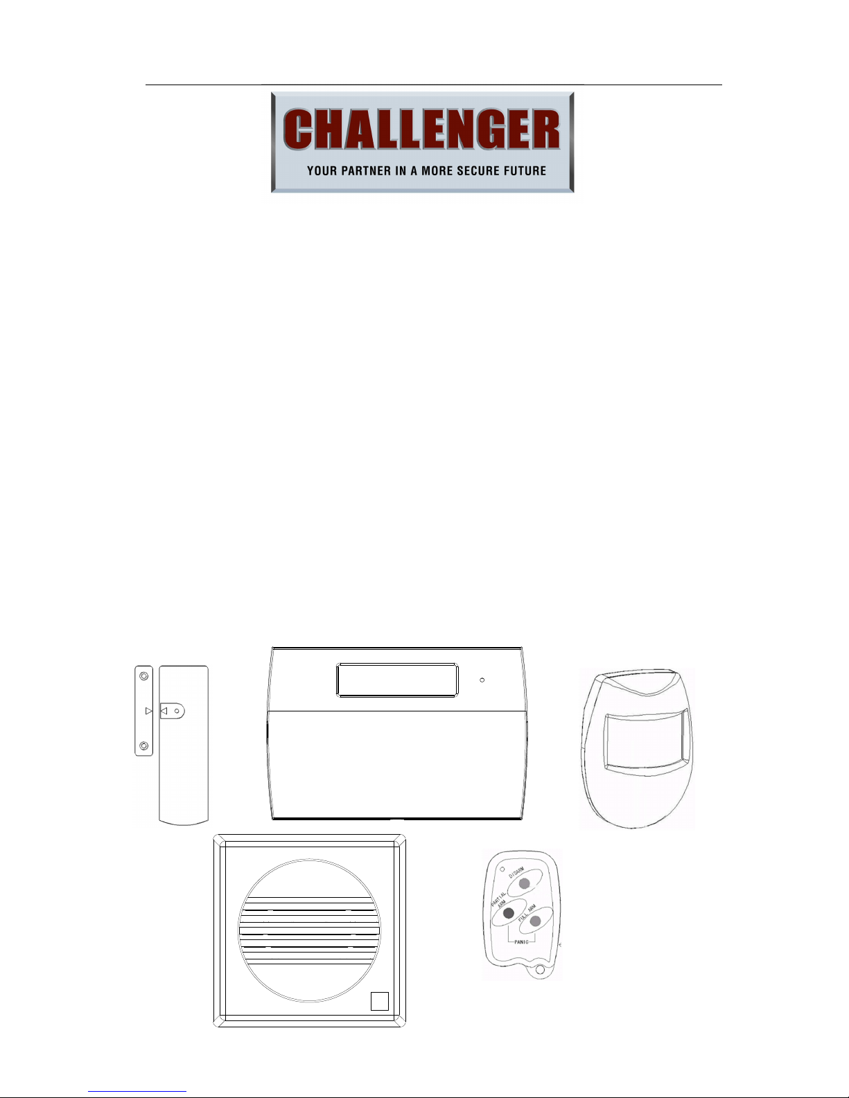
1.2 – Contents
- GSM Wireless Alarm Control Panel (CU) (One Unit)
This is the heart of the system. It receives signals from detectors.
Accepts input from a user and activates warning devices such as
siren and strobe lights.
- Wireless Door/Window Contact Detector (MC)(One Pair)
Uses a magnetically operated switch to sense the opening/closing of door or window.
- Wireless Movement / Passive Infrared Detector (PIR) (One Unit)
The PIR uses Infra-Red technology to sense body heat of a moving person. One unit
can cover an entire room.
- Wireless Remote Key (One Unit)
Used for full arming, part arming or disarming the system. In addition it is used for the
panic function. (fitted with 3V CR2032 lithium coin cell)
- External Sounder (One Unit)
Gives audible and visual indication of an alarm condition.
- Other accessories
External AC adaptor(One Unit)
The CU is pre-programmed to recognize the PIR/MC/Remote Key for immediate
operation after power supply is being connected properly.
Page 6

APFWKGSM GSM Wireless Alarm Operating Manual
APFWKGSM Manual Rev01
- 6 -
1.3 – Tools Required
• Large and small slotted screwdrivers
• Large and small Phillips screwdrivers
• Power drill
• Hammer
• 5mm, 8mm and 10mm masonry drill bits
• Sharp knife
• Wire cutters & wire stripper
•
Ladder or other safe working platform
1.4 – Explanation of Terms
Zone – A logical area that is monitored by one detector.
Disarm – It is the normal state of the system when the house is occupied. Enter your
four-digit user PIN code would return to OFF state.
Full Alarm (ARM state) – The CU will sound full alarm (internal siren) when it receives
alarm signals.
Part Arm (Home state) – Arming the system so that certain zones omitted (i.e. will not
trigger an alarm).
Entry/Exit Zone – The CU recognize MC zone as entry and/or exit zone.
OK Beep – Rapid double tone; it indicates correct operation.
Error Beep – Long single tone; it indicates incorrect operation.
Section 2 – Installing your System
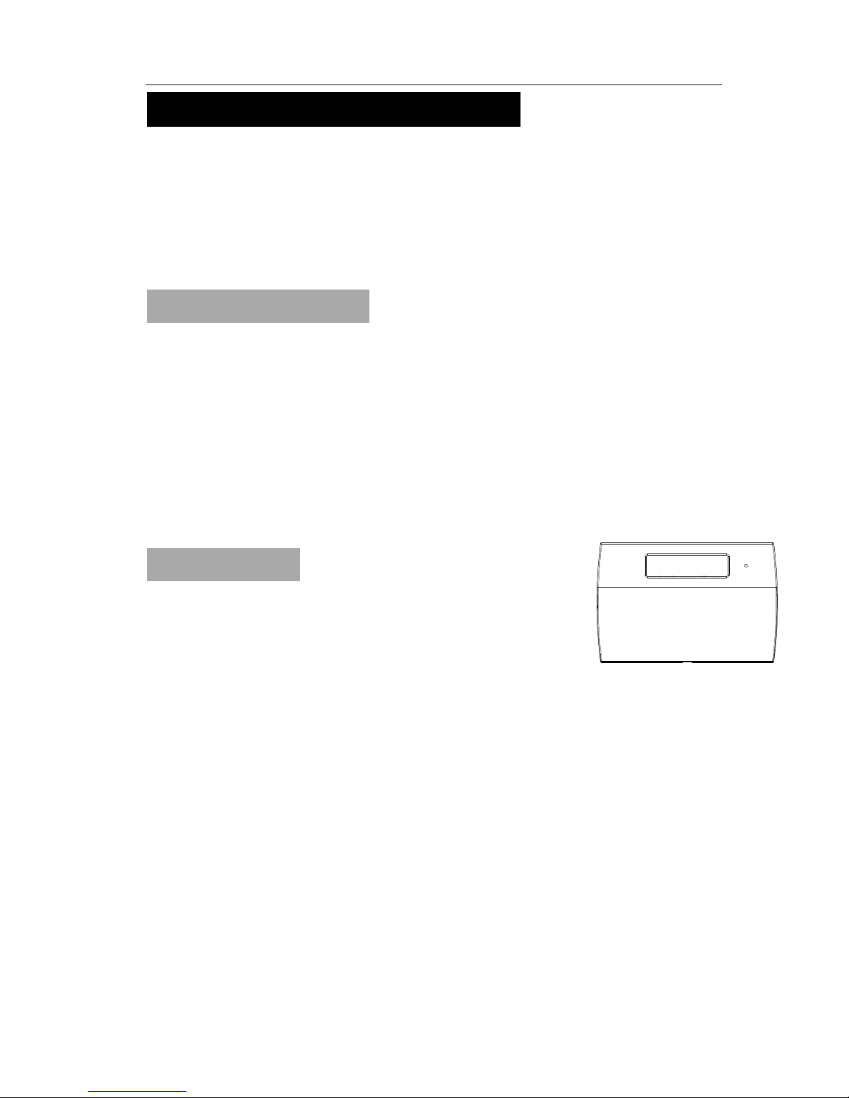
2.1 – Location of components
GSM Wireless Alarm Conrol Panel (CU) – Location
In choosing a suitable location you should bear in mind:
The need to reach the keypad easily, within the 99 seconds of entering and leaving
the premises ( ideally passing one detector).
The Alarm panel should not be visible from the exterior of the protected premises.
Reception of radio signals can be affected by the presence of metal objects within a
few feet of the CU. (E.g. mirrors, central heating radiators, garage doors and cars
parked in garages on the opposite side of the wall. Avoid any location which is near
(within 60cm) to these or any other large metal objects.
Having chosen the location, do not mount at this stage.
Wireless Door/Window Contact Detector (MC) – Location
These parts contain a radio transmitter and should not be situated
near large metal objects.
Contains two parts. The larger one (the actual detector) contains
the batteries and the electronics. The smaller part is simply a
magnet inside.
Page 7
APFWKGSM GSM Wireless Alarm Operating Manual
APFWKGSM Manual Rev01
- 7 -
PIR
2 - 2.5M
Designed to detect a door or window opening. The detector is usually
mounted next to it on the door or window. For optimum wireless range, they
should be mounted as high as possible.
In most applications, it is fitted to the front door.
Having chosen the location, do not mount at this stage.
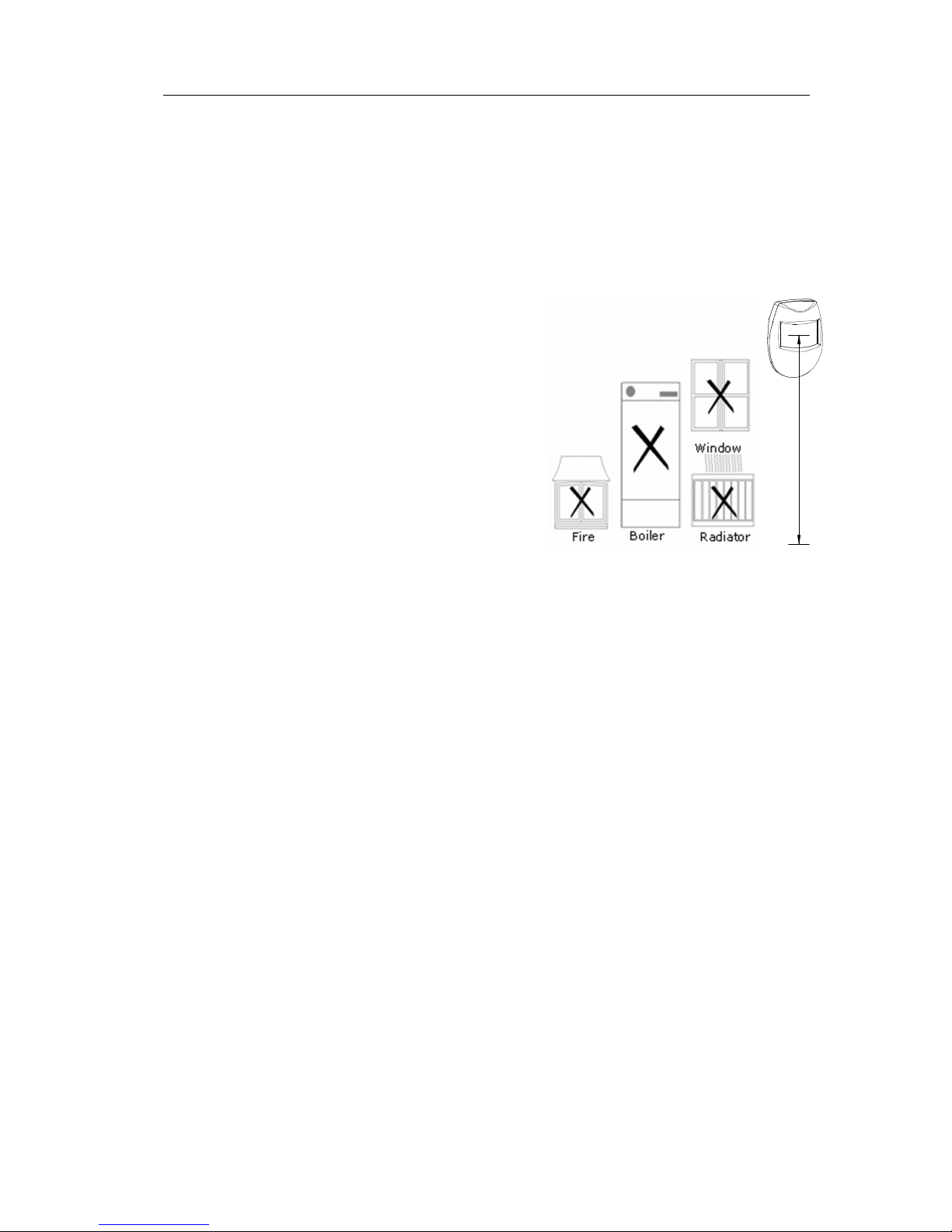
Wireless Movement / Passive Infrared Detector (PIR) – Location
The detector should not be mounted near to
large metal objects or on metal surfaces. It
needs to be mounted on a wall or in corner at a
height of approximately 2-2.5 meters for the
best general coverage in an average room. The
detector has been designed to avoid false alarms,
nevertheless, it is best to avoid installing the unit
where it is facing directly at sources of heat such
as fires and boilers and always try to avoid facing
at the window. A PIR can face at a radiator but
should not be situated above it.
Do not position a PIR where its field of view may be obstructed (e.g. by
curtains.)
Also, note that PIR works best when sensing a movement across rather than along
their detection beams.
Allowing for pets – The PIR senses moving body heat. In some cases, the
movement of pets may also be detected. To overcome this it is recommended that
the pets are kept in one specific room out of sight of a PIR when the system is
armed.
Having chosen the location, do not mount at this stage.
Page 8
APFWKGSM GSM Wireless Alarm Operating Manual
APFWKGSM Manual Rev01
- 8 -
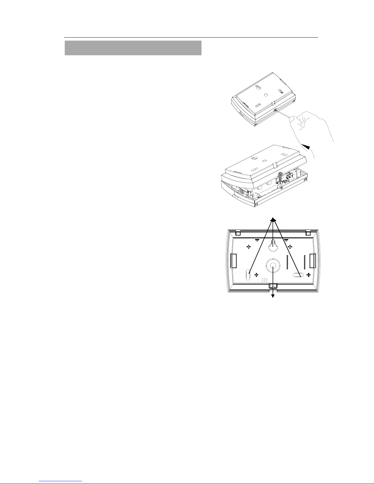
2.2 – Fixing the Control Panel
CAUTION: When positioning the control panel ensure that it is located in a dry place.
Step 1. Remove the backgraund cover(s) from the base assembly.
Step 2. Carefully remove the board by taking away screws at both edges
Step 3. Fit the panel to wall with suitable fixings. Ensure the
wall surface is flat to prevent base distortion. There are
cable entry holes provided in the rear of the base and
around the outside edges through the thinned out
plastic sections which may be cut away as required.
Step 4. The hole provided adjacent to the mains
transformer is a dedicated mains cable entry point.
Mounting hole
Cable Entry
Page 9
APFWKGSM GSM Wireless Alarm Operating Manual
APFWKGSM Manual Rev01
- 9 -
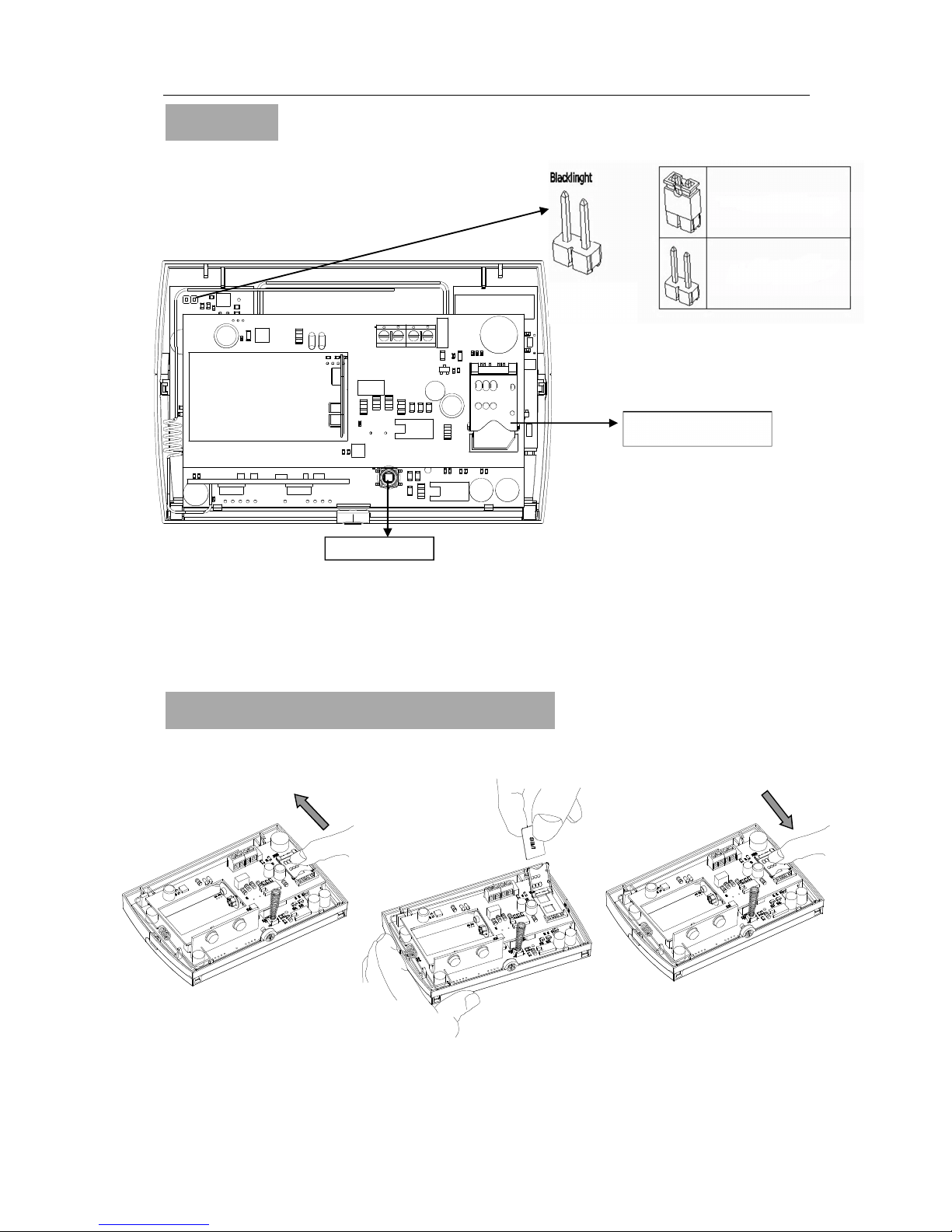
BACK LIGHT
- +
EXTERNAL
SIREN
~ ~
15V
AC IN
2.3 – PCB
CAUTION: Always power-down the panel when wiring external circuits, to prevent
damage to the panel electronics.
Systematically wire and test each circuit:
• Zone and Tamper circuit
• Finish by wiring any additional extension speaker sounders and the 13V supply.
2.4 – How to inset your SIM Card
When you insert the SIM card into panel ensure all power supply of panel is cut off.
a. Open the cover of card hold tray.
b. Insert the SIM card to the cover.
c. Close the cover and slide into the lock.
Tamper button
Press key back light on 5s
Back light constantly on
GSM Sim card tray
a)
b) c)
Page 10
APFWKGSM GSM Wireless Alarm Operating Manual
APFWKGSM Manual Rev01
- 10 -
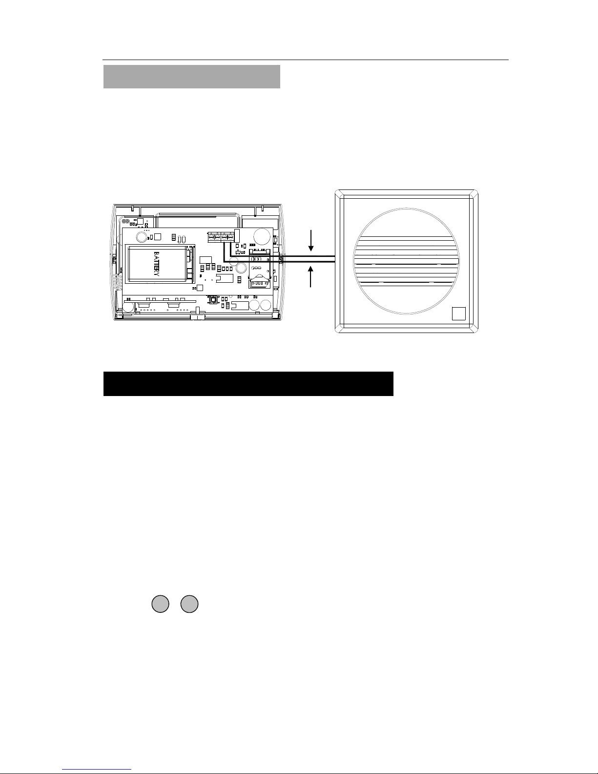
2.5 – Extension speaker
Extension speaker may be connected to the loudspeaker terminals to produce high
volume alarm tones.
External speaker connects to control panel
Extension speakers may be wired across the speaker terminals(Red to +and Black to -).
Mounted in convenient positions within the installation the extension speakers will
reproduce one of the alarm tones generated by itself.
Section 3 – Factory Default Setting
Defaulting Master code
1. Disconnect all power source to the unit
2. Repower system - After initializatied the alarm will start
3. Press & KEYS simultaneously for 5 seconds - this process takes around
10 seconds.
4. After Master Reset, enter 1 2 3 4 to silence alarm
System Status
Master code : 1234
Bell time : 3 minutes
System Time : 00:00:00
System Date : 01-01-12
Alarm INFO text is Null
Zone type : Security
GSM Receiving Signal Level Display : On
SET Mode
Full mode:
Zone 1-10 : Delay
Exit Mode : Timed Exit
Delay Time : 30 sec
Part 1 mode:
Zone 1-10 : Immediate
Exit Mode : Timed Exit
Delay Time : 30 sec
Extension Speaker
SET
RESET
~ ~
15V
AC IN
- +
EXTERNAL
SIREN
BACK LIGHT
‘-’(Black)
‘+’(Red)
Page 11
APFWKGSM GSM Wireless Alarm Operating Manual
APFWKGSM Manual Rev01
- 11 -
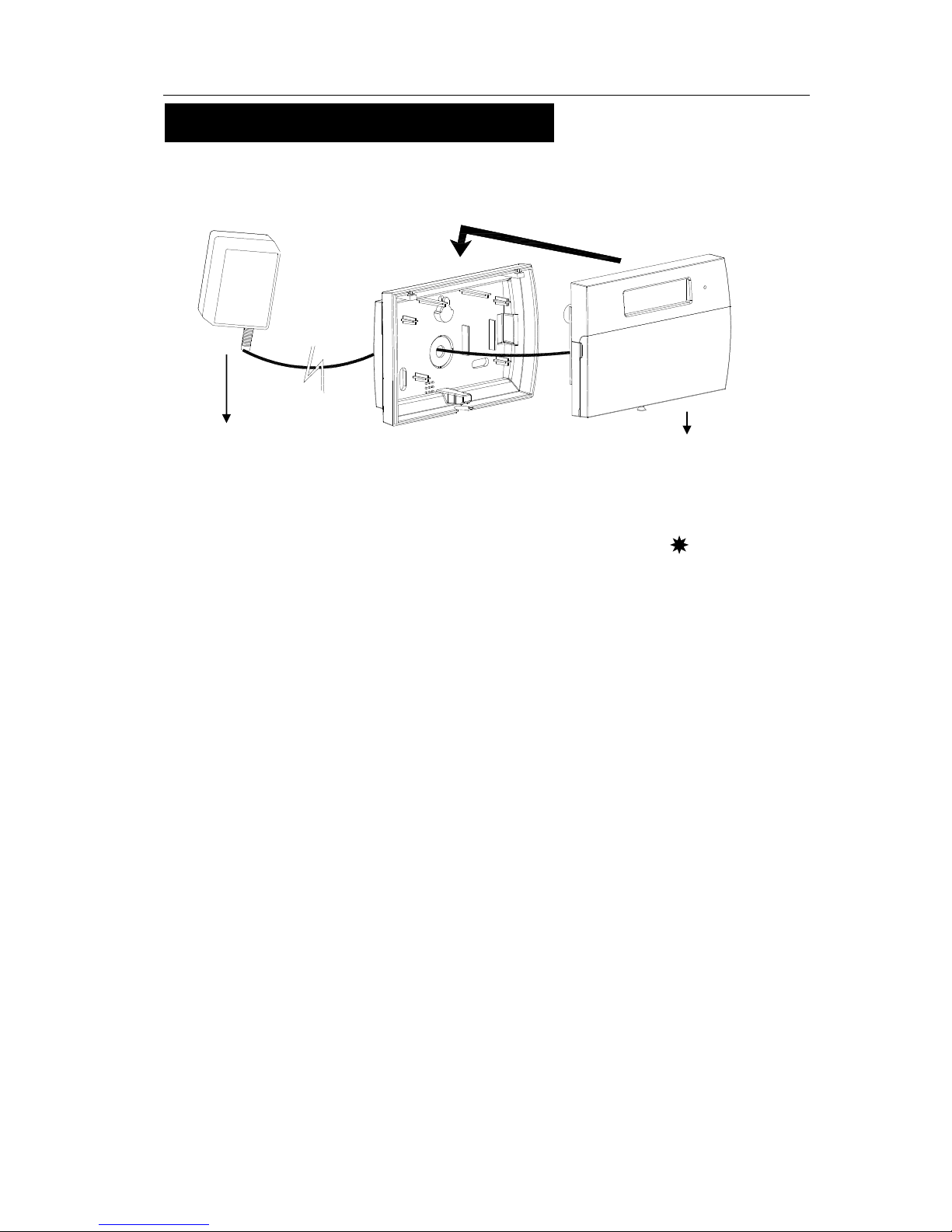
Section 4 – Mains Connection
The mains power should be connected using an AC/ AC Adaptor(AC230V/AC15V,
500mA).
CAUTION: To avoid the risk of electrical shock you must always totally isolate the mains
supply before opening the control panel cover(s).
On connecting the mains supply to the panel the power indicator is lit. Power
Testing the System
Complete the wiring of the system and then:
• Fully test the system and ensure it is fault free.
• Fully program the system.
• Fill in the installation log at the back of the manual and retain if for future reference.
Extenal 15V adaptor
GSM Wireless Panel
Page 12

APFWKGSM GSM Wireless Alarm Operating Manual
APFWKGSM Manual Rev01
- 12 -
Section 5 – First Power Up
Before powering up the GSM panel – fit the top cover on to the base. Connect the speaker
wires and the SIM Card inserted.
a. On connecting the battery the system will now go into alarm condition.
b. Fit the cover to hold down the tamper spring at the bottom right-hand of the board.
c. Enter Master code
(factory set code).
d. Press to return to Day mode.
Power Up
1 2 3 4
RESET
01-Jan 00:00
DAY
Battery Clip
Battery fixure
Page 13

APFWKGSM GSM Wireless Alarm Operating Manual
APFWKGSM Manual Rev01
- 13 -
Section 6 – How to Set up the system
Master Program Mode
The control panel may be programmed to suit a wide variety of installations.
Once the master program mode has been accessed, each configuration may be changed in
any order.
Before entering master program mode the system should be in Day mode.
The full menu structure for the panel can only be accessed while in master Program Mode.
The structure is shown in the following table:
6.1 – Set Mobile Number
6.1.1 – Entering Master Program Mode
It is accessed directly from Day mode via the Master code.
Entering the Master Opeation mode is as follow :
• Enter Manager program mode
Press
6.1.2 – Setting the Mobile Phone Number
·Under Master mode.
·Press keys to go into Set Mobile No function.
·Press to select phone 1
Note: =Phone 1, =Phone 2, = Phone 3
·Press to go into the Change Number function.
MENU OPTIONS
1 Register Mobile Number 5 Setup System
2 Setup Arm Setting 6 View alarm log
3 Setup Zone Name 7 Test System
4 Setup code 8 Setup Wireless Device
MASTER MENU
Set Mobile No.?
PROG
1 2 3 4
MASTER MENU
Set Mobile No.?
SET
1
SET
1
1
2 3
SELECT NUMBER
Mobile Number 1?
MASTER MENU
Set Mobile No.?
SET
SETUP NUMBER
Change Number?
1
Page 14

APFWKGSM GSM Wireless Alarm Operating Manual
APFWKGSM Manual Rev01
- 14 -
·Press keys to go into register mobile phone function.
·Input your mobile phone Number, max 16 digit.
Input phone number eg. 0412345678
·Press to save the phone number or press to cancel
and exit.
6.1.3 – Setting the Mobile Phone Name
·Under Master mode.
·Press keys to go into Set Mobile No function.
·Press to select phone 1
Note: =Phone 1, =Phone 2, = Phone 3
·Press to select the Change Number Name function.
·Press to go into the Change Number Name function.
·Press key, it will clear the last character.
·Press key, it will clear the line text.
[0]..[9] key have different characters.
_0 ,)?1 abc2 def3
ghi4 jkl5 mno6 pqrs7
tuv8 wxyz9
·Press key to toggle between capital and lower case letters. ABC-abc.
·Press key twice within 3 seconds, Capital 'H' will be shown on LCD.
INPUT MOBILE NO.
_
SET
INPUT MOBILE NO.
0412345678_
SET
RESET
MASTER MENU
Set Mobile No.?
SET
1
SET
1
1
2 3
SELECT NUMBER
Mobile Number 1?
MASTER MENU
Set Mobile No.?
SETUP NUMBER
Change Num Name
?
SET Number Name
?
Phone 1
2
SETUP NUMBER
Change Num Name
?
SET
SET Number Name
?_
0 1 2 3
4 5
6
7
9 8
4
SET Number Name
?
Phone
PROG
SET Number Name
?H
Page 15

APFWKGSM GSM Wireless Alarm Operating Manual
APFWKGSM Manual Rev01
- 15 -
·Press key twice within 3 seconds. Lower case 'e' will be
shown on LCD.
·Input “Helen” string.
·Press key to accept input and save the text,
·Press key, it will exit without change to the text.
6.1.4 – Deleting the Mobile Phone Number
·Under Master mode.
·Press keys to go into Set Mobile No function.
·Press to select phone 1
Note: =Phone 1, =Phone 2, = Phone 3
·Press to select the Delete Number function.
·Press to delete Mobile Number 1.
6.2 – Setup Programs
6.2.1 – Full mode Setting
·Under Master mode.
·Press to select Setup Programs.
·Press to accept and go into Setup Full Mode.
MASTER MENU
Setup Program
?
SELECT PROGRAM
Setup Full Mode
?
SET
2
SET
1
SET Number Name
?
Helen
SETUP NUMBER
Delete Number?
3
SET
RESET
SET Number Name
?He
MASTER MENU
Set Mobile No.?
SET
1
SET
1
1
2 3
SELECT NUMBER
Mobile Number 1?
MASTER MENU
Set Mobile No.?
3
SETUP NUMBER
Delete Number?
SET
SETUP NUMBER
Number Delete!
Page 16

APFWKGSM GSM Wireless Alarm Operating Manual
APFWKGSM Manual Rev01
- 16 -
6.2.2 – Part mode Setting
·Under Master mode.
·Press to select Setup Programs.
·Press to accept and go into Setup Part Mode.
6.2.3 – Setting zone function
In Zone Function, Security type zones can be assigned with different functions. These
are 1= Immediate Zone, 2 = Delay Zone
Immediate Zone:
Use this function when the zone is not part of an entry/exit route. When the system is
SET, activation of an immediate zone will cause a full alarm condition.
Delay Zone:
A time zone would be used to protect an entry/exit route. Opening the door or
triggering the sensor in this type of zone when the system is SET will start the entry
timer.
Under Master Menu/Setup Program, the program mode is chosen.
·Press to go into zone functions function.
·Select Zone No. using or key.
·Press to accept. Display zone current function.
·If press to select Immediate zone function.
·If press to select Delay zone function.
·Press to accept and return to next zone option or press
to cancel and exit.
Setup Full Mode
Zone Function
?
SELECT ZONE
Zone 1?
ZONE FUNCTION
Immediate
Z
one?
SELECT ZONE
Zone 2?
MASTER MENU
Setup Program
?
ZONE FUNCTION
Immediate
Z
one?
ZONE FUNCTION
Delay Z
one?
SELECT PROGRAM
Setup
Part Mode
?
SET
2
SET
2
SET
1
SET
1
2
SET
RESET
Page 17

APFWKGSM GSM Wireless Alarm Operating Manual
APFWKGSM Manual Rev01
- 17 -
6.2.4 – Setting Delay Time function
This is the time allowed to leave the premises via the exit route before the system arms
(Entry/Exit time), and entry route to disarm the system before the system goes into alarm.
The programmable range is 00-99 seconds.
The default is 30 seconds.
Under Master Menu/Setup Program, the program mode is chosen. ( Full or Part )
·Press to select Delay Time function.
·Press to accept. Display current exit time number.
Set the time by pressing number key. The range is 00-99.
eg. Set the exit time 15econds.
·Press number key, cursor moves to next a character.
·Then press number key, cursor move to next a character.
·Press to save, or press to cancel.
6.3 – Setup Zones Name
6.3.1 – Setting Zone Name
This option allows each of the ten zones to be given a name.
e.g. Change zone 5 name to Bedroom 1.
Under Master Menu.
·Press to select Set Zone Name function.
·Press to accept.
·Press keys to select zone 5.
Note: =zone 1, =zone 2, … = zone 10
·Press keys to go into setup zone name function.
Setup Full Mode
Delay
Time?
Delay Time
????
30
Setup Full Mode
Zone Function
?
Delay Time
????
10
Delay Time
????
15
MASTER MENU
Set Zone Name
?
SELECT ZONE
Zone 1?
SET ZONE TYPE
Zone Name?
ZONE NAME
????
Zone 5
2
SET
1
5
SET
RESET
3
SET
5
SET
1
2 0
1
SET
Page 18

APFWKGSM GSM Wireless Alarm Operating Manual
APFWKGSM Manual Rev01
- 18 -
·Press key, it will clear the last character.
·Press key, it will clear the line text.
[0]..[9] key have different characters.
_0 ,)?1 abc2 def3
ghi4 jkl5 mno6 pqrs7
tuv8 wxyz9
·Press key twice within 3 seconds. Capital 'B' will be
shown on LCD.
·Press key to toggle between capital and lower case letters. ABC-abc.
·Press key twice within 3 seconds. Lower case 'e' will be
shown on LCD.
·Input “Bedroom 1” string.
·Press key to accept input and save the text,
·Press key, it will exit without change to the text.
6. 4 – Change Code
6. 4.1 – Changing Master Code
Under Master Menu.
·Press keys to go into Setup Codes function.
·Press to accept and go into set the user.
·Input the 4-digit code, if you enter the wrong 4 digit code, an error tone will be generated.
·Press to save. If the 4-digit is the same as other codes,
then display and error tone generate,
·Press key, it will not change the code and exit.
ZONE NAME
????
Zone
ZONE NAME
????
ZONE NAME
????
B
ZONE NAME
????
Be
ZONE NAME
????
Bedroom 1
MASTER MENU
Change
Code?
MASTER CODE
*******
******
***
ZONE NAME
????
B
0 1 2 3
4 5
6
7
9 8
2
PROG
3
SET
RESET
4
SET
SET
MASTER MENU
Setup
System
?
RESET
SET
MASTER MENU
Change Code?
Page 19

APFWKGSM GSM Wireless Alarm Operating Manual
APFWKGSM Manual Rev01
- 19 -
6. 5 – Setup system
The catalog of Setup system contains five parts. They are list as follow:
1 = Bell Time, 2 = Set Time, 3 = Set Date, 4 = GSM Receiving Signal Level
Display, 5 = Reset NVM(
non-volatile memory)
6.5.1 – Entering Bell Time
This is the duration that the external bell output is active. The range is 01-20 minutes.
The default is 14 minutes.
e.g. Change the Bell Time from 3 to 10 minutes.
Under Master Menu
·Press keys to go into Setup System function.
·Press to select Bell Time function.
·Press to accept. Display current Bell time number.
Set the time by pressing number key. The range is 01-20.
·Press number key, cursor moves to the next a character.
·Then press number key, cursor moves to thenext a
character.
·Press to save it, or press to cancel, it will exit
and go to “Set Time”.
6.5.2 – How to Set Time
The time can be modified in hours, minutes in the format HH:MM. you must set it
correctly, or else System will generate an error tone and not save the change. key
will help you to select the bit that you want to change.
* Time and Date will be lost once the power supply from both main power and backup battery
are disconnected
e.g. Change the system time to 12:02.
Under Master Menu
·Press keys to go into Setup System function.
SETUP SYSTEM
Bell Time
?
BELL TIME
Min
????
03
SETUP SYSTEM
Set Time
?
BELL TIME
Min
????
13
BELL TIME
Min
????
10
SETUP SYSTEM
Bell Time
?
5
SET
1
SET
1
0
SET
RESET
5
SET
MASTER MENU
Setup
System
?
Page 20

APFWKGSM GSM Wireless Alarm Operating Manual
APFWKGSM Manual Rev01
- 20 -
·Press to select Set Time function.
·Press to accept. Display current time.
set new time to 12:02
·Press number keys.
·Press to save it and clear second time, or press to
cancel, it will exit and go to “Set Date”.
6.5.3 – Entering Set Date
Using digital keys or key to change the date, pressing the key
to save or pressing key to cancel. The date can be changed in day, month, year
format DD/MM/YY. The method of set date is the same as setting time.
e.g. Set current system date: 01-08-2012
Under Master Menu
·Press keys to go into Setup System function.
·Press to select Set Date function.
·Enter system date: Day/Mon/Year(6-digits)
·Press number keys.
·Press to save or press to cancel and it willl exit
the current menu.
SETUP SYSTEM
Set Time
?
Set Time HH:MM
0
0:00
SETUP SYSTEM
Set Date
?
Set Time HH:MM
12:0
2
SETUP SYSTEM
Set Date
?
SETUP SYSTEM
GSM Signal Dis?
Date DD/MM/YY
01/01/12
Date DD/MM/YY
08/01/12
2
SET
0 2 1 2
SET
RESET
SET
RESET
3
5
SET
1
1 0 0 8 2
SET
RESET
SETUP SYSTEM
Bell Time
?
SET
Page 21

APFWKGSM GSM Wireless Alarm Operating Manual
APFWKGSM Manual Rev01
- 21 -
6.5.4 – Setting GSM Signal Level Display
When this flag is set to ON, system will check the antenna of GSM module receving signal
level all the time and show level through this icon “ ”.
Under Master Menu
·Press keys to go into Setup System function.
·Press to select GSM Signal Diplay function.
·Press or key to toggle ON/OFF.
·Press to save or press to cancel and will exit
the current menu.
6.5.5 – Restoring to factory setting using menu
You will change the value of all parameters to factory default value when you set it.
CAUTION: All configurations of the panel are reset to reset to factory default conditions.
To default to factory settings:
Under Master Menu
·Press keys to go into Setup System function.
·Press to select Reset NVM function.
·Press key to go into Reset NVM function.
·Press to accept and system will generate an extended
acceptance tone, or press to cancel and will exit the
current menu.
6. 6 – View Event Log
The event log gives a display of all the events that has taken place. The events are
arranged by date and time. Up to 100 events can be stored in the memory. When the log
reaches 100 events and another event takes place, the first event drops out. The system
is known as FILO (First In Last Out).
To view the event log:
SETUP SYSTEM
GSM Signal Dis?
SETUP SYSTEM
Reset NVM
?
GSM Signal Dis
ON
4
5
SET
SET
RESET
SETUP SYSTEM
Bell Time
?
SET
SETUP SYSTEM
Reset NVM
?
SETUP SYSTEM
Bell Time
?
Are you sure?
Press
S to reset
5
5
SET
SET
RESET
SETUP SYSTEM
Bell Time
?
SET
* NVM is non-volatile memory
* NVM is Non-volatile memory
Page 22

APFWKGSM GSM Wireless Alarm Operating Manual
APFWKGSM Manual Rev01
- 22 -
Press: Jump to oldest event
Jump to newest event
Clear all alarm event
Move one event older
Move one event newer
····Under Master menu
·Press key to select View Event Log function.
·Press to accept and most recent event shown first.
·View other event log using or key.
·View event time and date using key.
·Press any key to return the current event log when viewing
the time and date
·Press to accept and system will generate an extended
acceptance tone. Or press key to exit
·Finished and return to next option.
6.7 – Test System
This function has three parts in Test System: Test Speaker, Walk Test, SMS Test.
6.7.1 – How to Test Speaker
····Under Master menu
·Press key to select Test System function.
·Press key to go into test system bell item.
·Press key to select speaker output test.
·Press key to accept and toggle test outputs ON,
or press key , it will leave the menu “Test System”.
MASTER MENU
View Event Log?
System Set
Master
Time : 00 : 28
Date :
12 - Jan
MASTER MENU
T
est S
ystem
?
Code Change
Master
Code Changed
Master
MASTER MENU
Test System
?
Speaker is ON
Press
any key
TEST SYSTEM
Speaker
?
6
SET
SET
SET
RESET
7
SET
1
SET
RESET
1
4
9
Page 23

APFWKGSM GSM Wireless Alarm Operating Manual
APFWKGSM Manual Rev01
- 23 -
·Press any key to stop output and menu return to next test option.
6.7.2 – How to perform Walk Test
The walk test function allows checking of each Zone trigger, Zone tamper, Detect Tamper,
Control panel tamper, Bell Box tamper, Remote Keypad tamper in order to verify that
they are functioning correctly. A tone is generated as each zone or tamper is activated
(open circuit).
e.g. Trigger Zone and Zone tamper
· Under Master menu
·Press keys to go into Test System function.
·Press key to select Walk Test function.
·Press key to go into walk test.
·The zone tested will be display in LCD,
if it isn’t displayed, check the Zone that you trigger.
·Press any key to exit “Walk Test”.
6.7.3 – How to perform SMS test set
·Under Master menu
·Press keys to go into Test System function.
·Press key to select SMS Test function.
·Press key to go into SMS Test function.
·System sends the message from phone 1 to phone 3.
·System will show “Test fail” when it registers a
wrong number.
TEST SYSTEM
Walk Test
?
TEST SYSTEM
Walk Test
?
Walk Test
TEST SYSTEM
Speaker
?
Zone Tested
Z1:Zone 1
7
SET
2
SET
TEST SYSTEM
SMS Test
?
TEST SYSTEM
Speaker
?
7
SET
3
SET
Test Message
Sending
…
Phone 1
Test OK!
Phone 1
Test Fail!
Page 24

APFWKGSM GSM Wireless Alarm Operating Manual
APFWKGSM Manual Rev01
- 24 -
·After sending all message, system will display “test finish”.
·If no phone number is registered, the unit will ask user to
register.
·Press any key to exit “SMS Test”.
6.8 – Setup Wireless Device
Up to 4 wireless remote keys and 10 wireless devices(PIR or MS) could be paried with the
control panel.
1 = Setup WL Key, 2 = Setup WL Zone
6.8.1 – How to pair wireless remote key
Wireless remote key which is paired to the CU may control cp to be full mode, part 1
mode and day mode.
· Under Master menu
·Press to select Setup WL Device function.
·Press keys to go into Setup WL Device function.
·Press key to select Setup WL Key function.
·Press any key on the wireless key to learn.
If wireless key have been entered into the system, process will be
unsuccessful.
·Press any key to exit the current menu.
SETUP KEY
Key 1 Learning
SETUP WL DEVICE
Setup WL Key?
8
SET
1
SET
Key 1
Leant OK!
MASTER MENU
Setup WL Device
?
SMS Test Finish
Press any key
Please Register
Phone Number
TEST SYSTEM
Speaker
?
Page 25

APFWKGSM GSM Wireless Alarm Operating Manual
APFWKGSM Manual Rev01
- 25 -
6.8.2 – How to delete all wireless remote keys
·Under Master menu
·Press keys to go into Setup WL Device function.
·Press key to select Setup WL Key function.
·Press key go into delete all keys function.
·Press key to delete key ID record or press to reject
change.
·Press any key to exit “Setup WL Key”.
6.8.3 – How to learn a wireless zone
Zone 1~ Zone 10 is all the wireless zones.
· Under Master menu
·Press keys to go into Setup WL Device function.
·Press key to select Setup WL Zone function.
·Press
key to go into Setup WL Zone item.
·Press keys to select zone 5.
Note: = Zone 1, = Zone 2, … = Zone 10
·Trigger wireless Device(PIR or MS).
Note: System emitting beep-beep sound indicate learning the
wireless device successfully.
·Press any key to exit the current menu.
SETUP KEY
All keys delete?
SETUP WL DEVICE
Setup WL Key?
8
SET
1
SET
All keys
ID code deleted
All keys
have been learnt
SET
RESET
SETUP WL DEVICE
Setup WL
Zone
?
SETUP WL DEVICE
Setup WL
Zone
?
SETUP WL DEVICE
Setup WL Key?
8
SET
2
SETUP ZONE
Zone 1?
SET
Zone 5 Learning
Trig WL Detector
5
1
2 0
Zone 5
Learn
t OK!
SETUP ZONE
Zone 6?
SET
Page 26

APFWKGSM GSM Wireless Alarm Operating Manual
APFWKGSM Manual Rev01
- 26 -
6.8.4 – How to delete a wireless zone
·Under Master menu
·Press keys to go into Setup WL Device function.
·Press key to select Setup WL Zone function
·Press keys to select zone 5.
Note: = Zone 1, = Zone 2, … = Zone 10
·Press key go into delete the zone function.
·Press key to delete zone ID record or press to reject
change.
·Press any key to exit the current menu.
6.8.5 – How to delete all wireless zones
·Under Master menu
·Press keys to go into Setup WL Device function.
·Press key to select Setup WL Zone function
·Press key go into delete all zones function.
·Press key to delete all zones ID record or press to
cancel change.
·Press any key to exit the current menu.
6.9 – How to Exit Master Program Menu
····Under Master menu
····Press key to return to top of master menu.
····When no fault(Main tamper), return to DAY mode.
····LCD show DAY mode.
MASTER MENU
Setup Program
?
RESET
SETUP WL DEVICE
Setup WL
Key?
8
SET
2
SET
Zone 5
ID code deleted
SETUP ZONE
Zone 1?
SET
RESET
SETUP ZONE
Zone 6?
Zone 5
H
as been learnt
5
1 2 0
SET
Zone 5
ID Code delete?
SETUP WL DEVICE
Setup WL
Key?
8
SET
2
SET
Zone 5
ID code deleted
SETUP ZONE
Zone 1?
SET
RESET
SETUP ZONE
Zone 6?
All zones
ID Code delete?
08-Jan 12:03
DAY
Page 27

APFWKGSM GSM Wireless Alarm Operating Manual
APFWKGSM Manual Rev01
- 27 -
Section 7 – Using System
After you have finished system settings, you can now use the system. This section gives
an operation of how to arm and disarm the system as well as how to reset after an alarm.
7.1 – Setting the System
The panel has two programs: Program Full, Program Part. Both can be programmed independently
in the master operations mode. So you can set the system to the corresponding mode: Full Mode,
Part Mode
7.1.1 – Using the keyboard on control panel to setup
·System is in Day mode.
····Enter 4-digit master code and wait
e.g. press
····The display will last 3 seconds.
·Prompt user to select arm mode
Press key to select Full arm mode,
Or press key to select Part arm mode,
Or press key to exit.
····Exit and check system faults.
System fault contains: Tamper Zone, CP tamper
····
If the system has fault an error message will be displayed on the
LCD. Please resolve the fault before entering the mode.
e.g. Detector 1 abnormal.
····When
there are no faults, the panel will
display “Exit–No Faults” and the
exit tone generated. Alarm will proceed to the selected mode
until the exit time is completed..Pressing the key will
quickly set the system.
····Arm mode is set.
Enter your code
***
===Welcome ===
Master
To Set Select
[F
ULL
] [P
ART
]
Exit–No Faults
Exit Faults…
Z1:Zone 1
Count down beep
1 2 3 4
SET
RESET
SET
08-Jan 12:03
08-Jan 12:03
DAY
Page 28

APFWKGSM GSM Wireless Alarm Operating Manual
APFWKGSM Manual Rev01
- 28 -
Note:
Wireless remote could set full mode and part mode.
Pressing the “disarm” botton
on the wireless key will disarm the system.
7.1.2 – How to use SMS to set the system
·System is in Day mode.
·Input command message “1234armf” to set system
FULL Mode.
·Input command message “1234armp” to set system
PART Mode.
When no fault, it will display “Exit–No Faults” and the
exit tone will be generated
Note:
a, The SMS message is Case-insensitive.
b, If there is a zone that is open, system will feedback a message.
“Zone open, Zone No”.
····Arm mode is set.
7.1.3 – Disarming the System
To disarm the system in SET as follows.
·System is in the SET mode
·Input 4-digit master code.
e.g. press
····System will be reset and work in DAY mode.
7.1.4 – How to use SMS to reset the system
·System is in the ARM mode
·Input command message “1234disarm” to set system to
DAY Mode.
Enter your code
***
1 2 3 4
08-Jan 12:03
DAY
22-May 15:30
08-Jan 12:03
DAY
Exit–No Faults
08-Jan 12:03
Count down beep
08-Jan 12:03
08-Jan 12:03
DAY
Page 29

APFWKGSM GSM Wireless Alarm Operating Manual
APFWKGSM Manual Rev01
- 29 -
7.1.5 – How to DISARM the Alarm and RESET the
system
You can disarm the system in SET and reset it after an alarm or tamper.
e.g. Control Panel tamper trigger alarm
·System work in SET mode
·Enter master code
e.g. press .
·It will stop system in alarm and the LCD will
display the message of newest alarm event.
Hint (the display will scroll the following two screens)
·Press or enter master code to reset.
Then system return to Day mode.
7.1.6 – How to use Panic Alarm on keypad
Should you need to attract attention, the full alarm signal can be activated in an
emergency by pressing 0 and 5 together
Press & simultaneously, the system and external sounder will sound immediately.
7.1.7 – How to use Panic Alarm on wireless key
Pressing the PARTIAL ARM & FULL ARM key on wireless key simultaneously will
cause the system and external sounder sounding immediately.
0 5
CP Tamper
User Restore
Press Reset
Unset System by
Master
1 2 3 4
RESET
08-Jan 12:03
DAY
D
I
S
A
R
M
PANIC
F
U
L
L
A
R
M
P
A
R
T
I
A
L
A
R
M
08-Jan 12:03
Page 30

APFWKGSM GSM Wireless Alarm Operating Manual
APFWKGSM Manual Rev01
- 30 -
7.1.8 – SMS Content of feedback for system action
Action event SMS content
ARM Full action(1234armf)
System is in Full Mode.
--Phone Name.
ARM Part action(1234armp)
System is in Part Mode.
--Phone Name.
DISARM action(1234disarm)
System is in Day Mode.
--Phone Name.
DISARM action(1234disarm)
System is disarmed from alarm.
--Phone Name.
Zone trigger System Zone Trigger, Zn:Zone Name
Wireless Zone tamper System Zone Tamper, Zn: Zone Name
CP tamper System Tamper, CP Tamper
Panic alarm System Panic Alarm
GSM TEST SMS Self Test
ARM action
(1234armf or 1234armp)
When Zone open
Zone Open
Zone No
Section 8 – Maintenance
Once every three months,
• Test all detectors.
• Check speaker of control unit.
Additionally, once every year,
• Test detector feature
Additionally, once every two years,
• Replace the 9V alkaline battery in the Control Unit.
Section 9 – Troubleshooting Guide
Control Unit (CU)
Symptoms Possible cause & cures
Power indicator does not light up.
Main supply is out. It is operating from backup
battery. Check power connections/adaptor.
TAMPER Tamper triggered, check panel tamper.
No response to keystroke Power reset (both mains and backup battery)
Page 31

APFWKGSM GSM Wireless Alarm Operating Manual
APFWKGSM Manual Rev01
- 31 -
Wireless Door/Window Contact Detector (MC)
Symptoms Possible causes and cures
Does not detect opening of door or
window (Red LED does not flash)
Check that batteries are correctly installed.
Check that magnet is correctly positioned.
Built-in buzzer makes a sound Batteries are low. Replace batteries
Wireless PIR detector (PIR)
Symptoms Possible causes and cures
Does not detect movement
(Red LED does not flash)
Is PIR’s LED turned off?
Is the PIR in its “sleep” condition (Section 3.4)
PIR causes false “intruder” alarms. Check that
PIR is not pointed at heat sources or
moving objects, and is not mounted above a
radiator or other heater.
PIR will not trigger alarm when the
system is set.
PIR in “sleep” condition.
Built-in buzzer makes a sound Batteries are low. Replace batteries
Wireless Remote Control
Symptoms Possible causes and cures
Does not transmit
(Red LED does not flash)
Check that the battery is correctly installed.
Battery low, replace battery
Remark: If you have any problem with the alarm system. To default to factory settings,
please follow sections 5 explained in this manual.
Page 32

APFWKGSM GSM Wireless Alarm Operating Manual
APFWKGSM Manual Rev01
- 32 -
Section 10 – Specifications
GSM Wireless Alarm Panel
Type of Alarm Panel Microprocessor based control unit
Housing ABS
Entry Delay default 30 seconds, programmable
Exit Delay default 30 seconds, programmable
Alarm Zone 10 Zones - Programmable function
External Speaker DC12V 16ohm, max current : 200mA
Siren Duration Default 3 minutes
Current consumption control panel
Standby : 75mA
Alarm : 240mA
Battery input voltage Alkaline battery DC9V, 450mAh
Mains supply voltage 15V AC (+/- 10%) 50Hz max load 0.5A
Ambient operating temperature
0℃ ~ 40℃
Dimensions (mm) 253 x 195 x 61
Wireless Door/Window Contact Detector
Type
Magnetically activated switch with option for
external wired contact detectors
Housing ABS
LED Transmission indication
Transmission Frequency 433MHz
Transmission Range 120 meters (open air with direct line of sight)
Power Supply
3VDC (2x 1.5V
LR03 size AAA alkaline batteries
are not included)
Wireless Movement / Passive Infrared Detector
Type
Dual Pyroelectric element with hemispherical
lens
Housing Material On/off selectable
LED default 30 seconds, programmable
Mounting Height 2 ~ 2.5 meters
Page 33

APFWKGSM GSM Wireless Alarm Operating Manual
APFWKGSM Manual Rev01
- 33 -
Wireless Remote Key
Type
Microprocessor based wireless remote control
key
Housing Material ABS
LED Transmission indication
Transmission Frequency 433MHz
Transmission Range 30 meters (open air with direct line of sight)
Power Supply 3VDC (1 x CR2032 Lithium Coin size Battery)
External Sounder
Housing Material ABS
Rated Voltage 12VDC
Sound Output Level 105dB
Control Panel External Power Supply
Type AC/AC Adaptor
Housing Material ABS
Rated Supply 230VAC 50HZ supply
Output Extra Low Voltage (AC15V max at 500mA AC)
Detection Range 12 meters @ 110o
Transmission Frequency 433MHz
Transmission Range 120 meters (open air with direct line of sight)
Power Supply
3VDC (2x 1.5V LR03 size AAA alkaline batteries
are not included)
Page 34

APFWKGSM GSM Wireless Alarm Operating Manual
APFWKGSM Manual Rev01
- 34 -
Appendix 1 – Event Log Messages
Keypad text Description
Power up Supply power on
Code Changed
Master
Master code be changed
Battery Low Battery low voltage
Battery Low
Z No: Zone Name
Wireless Zone Low battery
AC Power Off Mains power supply failure
System SET System into Set mode
System Disaram User has disarmed the system
Disarm from Alarm User has disarmed the system from alarm
Intruder Alarm Intruder zone activated (opened)
Entry Start Entry time started
PANIC Alarm Panic zone activated (opened)
CP Tamper Control panel tamper opened
Zone Tamper
Z No: Zone Name
Zone tamper opened
Page 35

APFWKGSM GSM Wireless Alarm Operating Manual
APFWKGSM Manual Rev01
- 35 -
Appendix 2 – Zone - Location Table
Zone Number
Location
1
2
3
4
5
6
7
8
9
10
Disposal and Recycling
Batteries and waste electrical products should not be disposed of with household waste.
Please recycle where these facilities exist.
Due to our policy of continuous improvement we reserve the right to change
specification without prior notice.
Errors and omissions accepted. These instructions have been carefully checked
prior to publication. However, no responsibility can be accepted by Challenger
Security Products for any misinterpretation of these instructions.
Page 36

APFWKGSM GSM Wireless Alarm Operating Manual
APFWKGSM Manual Rev01
- 36 -
CHALLENGER SECURITY PRODUCTS
10 Sandersons Way
Marton
Blackpool
FY4 4NB
Tel No: 0044 1253 791 888
Tech No: 0044 1253 792 898
Website: www.challenger.co.uk
Email: enquiries.challenger@adivision.co.uk
 Loading...