

Page 1
APFW10 wireless module operating manual
Operating Manual
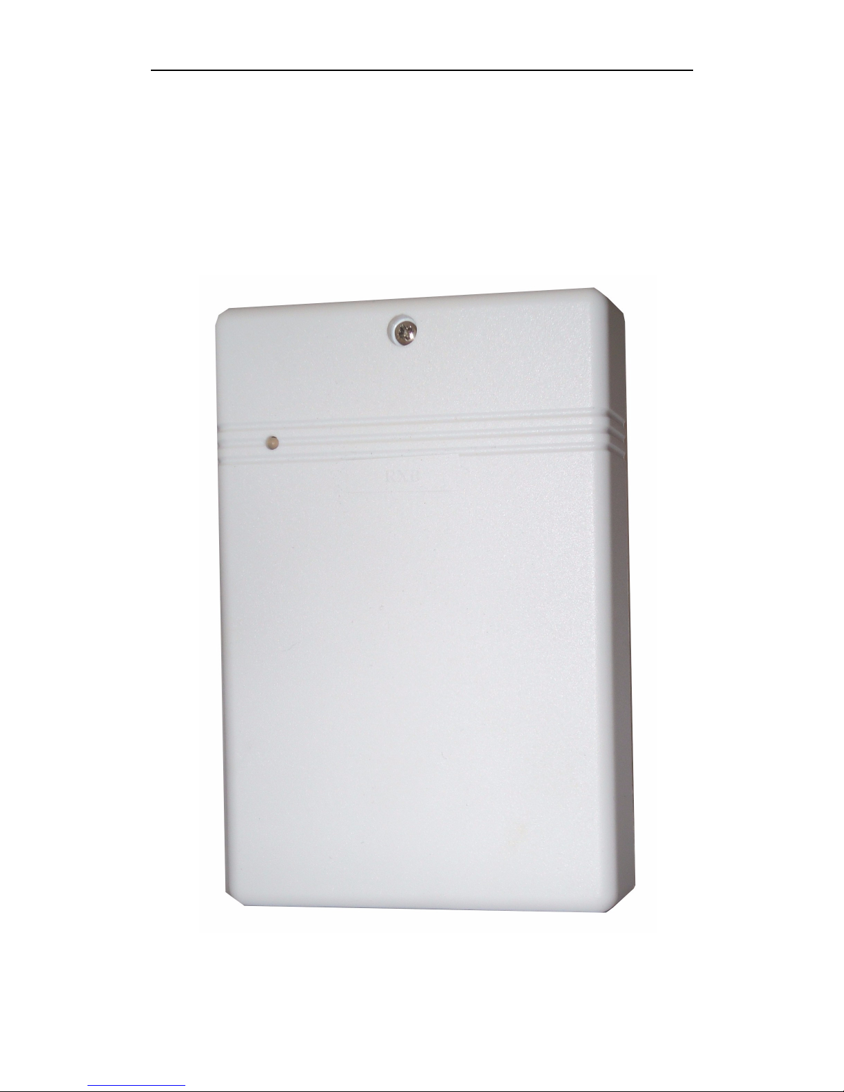
Easy Set Module APFW10
Page 2

APFW10 wireless module operating manual
Table of Contents
1. Features
....................................................................................................................3
2. Overview
..................................................................................................................3
3. Wiring diagram
.............................................................................................4
4. Extending the System
.......................................................................5
5. Installing the unit
....................................................................................6
6. Wireless Detectors Learning
..................................................7
7. Using the system
.......................................................................................8
8. Summary of LED Response
.......................................................9
9. Specification
......................................................................................................9
Page 3
APFW10 wireless module operating manual
1. Features
Allow the AP11 alarm control panel become wireless alarm system
Link to 20 wireless PIR(ADFW1)/wireless Magnetic Contact(ACFW1) and
4 Wireless remote keys (AUWFOB) in maximum
Arm and disarm alarm by remote key
Power up by Alarm Control Unit, no extra power source is needed
Status LED indication
Tamper protection
Anti-jamming detection
Detectors low battery detection
Detectors Supervision
Alert buzzer
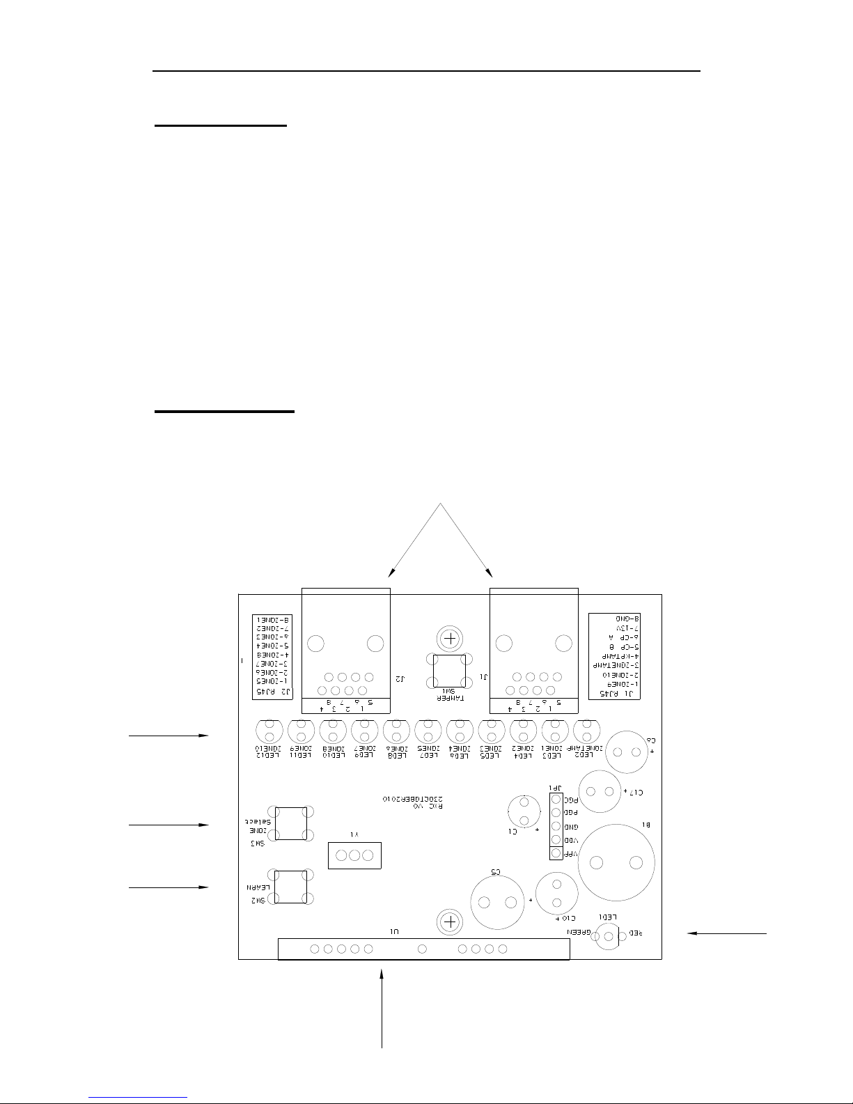
2. Overview
1 – RJ45 Socket
2 – Zone indicating LED
3 – Zone Select Button
4 – Learn Button
5 – RF Module
6 – Power LED
5
4
2
6
3
1
Page 4

APFW10 wireless module operating manual
3. Wiring diagram
Easy Set module APFW10 connect with Force-10 AP11 alarm control panel
Green
Blue
Orange
White/Green
White/Blue
White/Brown
Brown
Green
Blue
Orange
White/Orange
Brown
White/Orange
White/Green
White/Blue
White/Brown
Page 5

APFW10 wireless module operating manual
4. Extending the System
A number of accessories are available to extend your system to suit your
exact requirements. When extending the system, please note the system
can take up to 20 wireless PIR(ADFW1)/wireless Magnetic Contact(ACFW1)
and 4 Wireless remote keys (AUWFOB) in maximum
Wireless PIR (ADFW1)
– easy to install, one unit protects a large area.
Wireless Magnetic Contact (ACFW1)
– easy to fit, detects opening of a door or window, can be
extended by the addition of wired magnetic contact.
Wireless Remote Key (AUWFOB)
– can be used to arm, part-arm, disarm or panic the CU
system with an operating range of about 60 meters in open
field conditions..
Page 6

APFW10 wireless module operating manual
5. Installing the unit
Page 7

APFW10 wireless module operating manual
6. Wireless Detectors Learning
How to go into learn mode
Press Learn button on APFW10 board, it gives one beep, then yellow LED is
on to indicate learn mode now after release off.
How to learn a valid pin of control panel from wiring remote keypad.
The APFW10 acts as if the user has entered a valid PIN code. To achieve this,
the system needs to learn the PIN code. Under learn mode, Input 4 - digital key,
Red LED on APFW10 board will flash fast twice and give two beeps to indicate
OK.
How to register wireless detector into RXC module.
Under learn mode, trigger unregistered wireless detector, Red LED on
APFW10 board will flash fast twice and give two beeps to indicate OK. The
APFW10 will be ready to learn the next wireless detector. A zone LED will jump
to next zone LED indicate when it has learnt 2 detector. The APFW10 may
register maximum twenty detectors (ten zones, each of zone may be registered
by two detectors ). It will exit learn mode when unregistered wireless detector
has not signal over 10 second and doesn’t receive any hit button signal from
other wiring remote keypad.
How to register wireless remote key into APFW10 module.
Under learn mode, press any key on unregistered wireless remote key, Red
LED on APFW10 board will flash fast twice and give two beeps to indicate OK.
The APFW10 will be flash the yellow LED and ready to learn the next wireless
remote key. The APFW10 may register maximum four wireless remote keys. It
will exit learn mode when unregistered wireless detector and wireless remote
key have not signal over 10 second and doesn’t receive any hit button signal
from other wiring remote keypad.
Page 8

APFW10 wireless module operating manual
7. Using the system
How to set control panel going into FULL ARM, PART ARM via
wireless remote key?
Under system is DAY mode, press [ FULL ARM ] or [ PART ARM ]button of
registered remote key, control panel will go into FULL or PART mode with
delay a little time.
How to set control panel into OFF MODE via wireless remote key?
Under system is ARM mode, press [ DISARM ] of registered remote key,
control panel will return to OFF mode at once.
What to do if PIN code in alarm panel changed.
When the original user PIN code in the control panel is changed, you
must relearn the PIN code. (See section 6) We suggest programming a
different user code for the APFW10 than the standard user code. (2 user
codes plus a manager code can be programmed in panel)
How to clear valid pin and register wireless detector/device to restore
factory default setting?
In normal mode (Green LED on), Press button on APFW10 board for more
than 6 seconds, APFW10 gives two beeps when factory default completed.
Then release button
When do supervisor signal appear for APFW10 ?
System indicates message:
Below is Zone LED status when Wireless detector trigger.
Detector Action Zone LED Status
PIR trigger Light on about 2 seconds
MC open ON
MC close OFF
Tamper from PIR or MC Light on about 2 seconds
Missed zone(No supervision signal) Light on about 2 seconds
Page 9

APFW10 wireless module operating manual
8. Summary of LED Response
Below is double colour LED indicating status
Status
colour
Light on Flash twice Slow flash
Green Normal mode Low battery
Red Supervisor Learn ok Anti-Jamming
Yellow
Learn
mode(PIR&MC)
Learn mode(key)
When APFW10 working in learn mode, Z1 LED – Z10 LED indicate status:
LED flash slowly hint ready to learn the first detector to zone, LED flash fast hint
to learn the second detector, while LED light on indicate the zone be learned.
In Learn mode, APFW10 Learning Key status & PIR, MC status toggle
automatically when the rx signal enter.
Note: If APFW10 miss detector or doesn’t receive supervisor signal of any
detector, then it light on the corresponding zone LED about 2 seconds.
9. Specification
Housing ABS
Dimension
15×100×30mm;
5-7/8in×3-15/16in×1-3/16in
Power Supply: DC 9V to 14V
Standby 20mA Current Consumption:
Alarm 100mA
Security Wireless Zones: Up to 20PCS
User Remote Key: Up to 4PCS
Radio System:
433MHz AM Receiver
Wireless MC,PIR Range:
Up to 160 m
Wireless remote key 50m
Anti-jamming Yes
Tamper: Yes
Supervision: Yes
PA: Yes
Ambient Operating temperature: 0℃ to 40℃
Note : Default ID address of APFW10 is 0x04 (no jump setting).
Page 10

APFW10 wireless module operating manual
Distributed by;
Challenger Security Products
4 Arkwright Court,
Fylde Industrial Estate
Blackpool
FY4 5DR
Tel: 01253 792898
Fax: 01253 791887
Email: Enquiries.challenger@adivision.co.uk
Web: www.challenger.co.uk
 Loading...