

Page 1

0
o
R
d
c
X
d
A
&
8
k
P-SE
IES M
ANU
L
P10
P
0X, P
were
Instru
1500
Lou
tion Manual
P1
spea
(English)
00SX
ers
Page 2

CERWIN-VEGA! PROFESSIONAL
To avoid injury, read all operating instructions and safety information in this
manual before using the speaker.
Failure to follow these safety instructions could result in fire, electric shock, or
other injury or damage to the speaker or other property.
Contents
IMPORTANT SAFETY INSTRUCTIONS ....................................................................................................................................... 3
REGULATORY CERTIFICATION ................................................................................................................................................. 5
Introduction ............................................................................................................................................................................ 6
Before you begin ..................................................................................................................................................................... 6
Quick Start ............................................................................................................................................................................... 7
Loudspeaker placement .......................................................................................................................................................... 7
P1000X and P1500X Mixer - Rear Panel ................................................................................................................................. 8
P1800SX Mixer - Rear Panel .................................................................................................................................................. 11
P1000X, P1500X and P1800SX Power Connections - Rear Panel .......................................................................................... 13
Using the P1000X and P1500X as a floor/stage monitor ...................................................................................................... 14
Using the pole mount – P1000X only .................................................................................................................................... 14
Using the pole mount – P1500X only .................................................................................................................................... 15
Using the suspension points ................................................................................................................................................. 16
Application #1 – Single P1000X or P1500X ........................................................................................................................... 17
Application #2 – Adding a second P1000X or P1500X .......................................................................................................... 18
Application #3 – Adding Subwoofers .................................................................................................................................... 19
Application #3 – Adding Subwoofers (Adjusting HPF & LPF Filters continued) .................................................................... 20
Application #4 – Daisy-Chain ................................................................................................................................................ 21
Application #5 – Adding a P1000X or P1500X as a Stage Monitor ....................................................................................... 22
Application #6 – Large Venue/Front of House ...................................................................................................................... 23
Protective Grill ...................................................................................................................................................................... 24
Remote Main Volume ........................................................................................................................................................... 24
System Block Diagram (P1000X and 1500X full-range loudspeaker) .................................................................................... 25
System Block Diagram (P1800SX subwoofer) ....................................................................................................................... 25
Troubleshooting .................................................................................................................................................................... 26
Care and Maintenance .......................................................................................................................................................... 28
Appendix A – Cable Connections .......................................................................................................................................... 28
Warranty ............................................................................................................................................................................... 30
How to Obtain Warranty Service .......................................................................................................................................... 32
2
Page 3

C
o W
o
C
Cso CTt
W
s
d f T T
e
u
o
h
d
a
e
A
d
i
w
n
h
e
u
u
o
y
d
c
a
c
d
e
n
h
E
s
a
s
o
e
o
s
h
l
a
s
q
m
r
e
b
o
c
e
o
s
d
o
u
t
O
n
a
t
n
r
e
n
p
e
v
h
o
e
s
c
A
s
y
d
e
o
M
T
y
e
t
n
e
i
u
d
e
n
t
a
m
g
u
g
g
a
a
D
u
o
i
d
v
g
e
n
e
o
a
,
t
u
o
a
s
U
r
I
a
y
o
u
t
u
o
t
t
u
s
a
y
l
d
,
u
u
e
s
t
n
u
h
t
N
h
t
n
t
t
e
t
n
C
n
a
e
m
i
e
,
r
n
t
o
(
o
n
a
g
r
a
t
p
d
v
,
g
x
s
c
o
c
u
p
g
r
R
AUTION: Th
presence of
f electric sh
e lightning fl
n-insulated d
ck to person
IM
sh with an
angerous vol
.
CERWIN
PORTAN
rrowhead s
age within th
-VEGA! PROF
SAFETY I
mbol within
e unit’s encl
ESSIONAL
NSTRUCT
an equilater
sure that ma
ONS
l triangle is i
be of suffici
ntended to
nt magnitud
lert the user
e to constitu
to the
e a risk
ARNING: T
perating an
NOTE: The h
information r
AUTION: To
parts inside.
a) Rea
b) Reta
c) All
AUTION: To
place objects
bath tub, or
olvents or c
r when unus
AUTION: Th
it should not
installation, s
he unit sho
hat produce
ARNING: D
erious injur
recommende
NOTE: Shoul
isposal of el
e exclamati
maintenanc
nd within an
garding the
reduce the ri
ll servicing s
and follow a
in this user m
arning on the
reduce the ri
containing li
ear a swim
emically imp
ed for long p
unit should
be situated
ch as a book
ld be situate
heat. No nak
not place t
to a child
by the ma
i
nstructions a
ombination
ppliance an
ombination t
the unit bec
ctronic prod
n point with
(servicing) i
equilateral t
peration of t
ks of fire or
ould be refer
l the safety a
anual for futu
unit and its
ks of fire or
uid such as
ing pool. Un
egnated clot
riods of time
e installed s
n a bed, sofa
case or cabin
d from heat
d flame sour
his unit on a
r adult and
nufacturer.
nd should u
should be m
cart combin
o avoid injur
me damage
cts in your r
in an equilat
structions in
iangle is inte
he unit, and s
lectric shock
red to qualifi
d operating
re reference.
ackaging sho
lectric shock
ases or glass
plug the unit
s. For cleani
.
that its loca
, rug or simil
t, that may i
ources such
es, such as li
n unstable s
serious dam
ny mountin
e a mountin
oved with c
ation to over
from tip-ove
beyond rep
gion.
ral triangle
he literature
ded to alert
hould be rea
do not remo
d service en
nstructions b
ld be read a
o not expos
s on apparat
from the wa
g always use
ion or positi
r surface th
pede the flo
as radiators,
hted candles
rface, cart, s
age to the
of the devi
accessory r
re. Quick st
turn. When
r.
ir, or reache
s intended t
accompanyin
the user to s
fully before
e any covers,
ineers.
fore connec
d followed.
this product
us. Do not
ll outlet befo
a soft dry cl
n does not in
t may block
w of air thro
heat register
should be pl
and or tripo
nit. Use onl
ce on a wal
ecommende
ps, excessiv
cart is used
s the end of i
alert the u
g the produc
pecific guida
sing the unit
or open the
ing or using t
to rain, mois
se this produ
re cleaning.
th. Unplug t
erfere with i
he ventilatio
gh its ventila
, stoves or o
ced on, or n
d, bracket or
with a car
or ceiling s
by the ma
e force and
use caution
ts life, please
er to the pr
.
ce and infor
for the first t
nit. There ar
is unit.
ure, dripping
ct near wate
ever use thi
is product du
s proper ven
openings;
ion openings
her devices
ar the unit.
table. The u
, stand, trip
hould follow
ufacturer. A
uneven surf
when movin
consult the
sence of im
ation regar
me.
no user-ser
or splashing.
for example
ner, cleanin
ring lightning
ilation. For e
r placed in a
and/or fan a
including am
nit may fall,
d, bracket
the manufa
appliance a
ces may ca
the cart/ap
egulations re
ortant
ing the
iceable
Do not
near a
fluids,
storms
ample,
built-in
sembly.
plifiers)
ausing
r table
turer’s
nd cart
se the
aratus
arding
3
by improper
G TO THE W
otective gro
se of the uni
IDE WALL SO
nd(earth) co
t and or the
KET SLOT AN
nection.
pplications p
D FULLY INSE
ovided
T.
NOTE: Cerwi
or use with t
O PREVENT
he apparatu
-Vega canno
e unit.
LECTRIC SH
shall be con
be held resp
CK, MATCH T
ected to a
nsible for da
HE WIDE BLA
ains socket o
mage caused
E OF THE PL
tlet with a p
Page 4

t2t3td456
7
8
9
TTOTT
T
T
T9OsTaoyT
a
n
e
e
m
f
e
n
a
t
p
t
t
u
f
b
s
d
p
s
t
o
a
a
t
l
c
m
p
w
u
y
g
t
i
u
c
c
N
t
R
d
g
i
o
e
n
s
f
e
a
t
m
t
O
y
w
a
u
u
r
n
N
e
m
p
u
m
l
n
t
e
n
e
y
h
w
e
P
a
u
h
CERWIN
e
t
a
o
m
n
F
m
n
b
e
g
n
t
r
d
.
t
n
e
a
a
w
g
t
C
u
g
r
c
n
.
a
m
n
T
c
e
s
v
u
a
a
a
A
n
e
n
o
i
c
A
e
O
c
n
f
t
0
e
O
A
h
o
e
u
o
t
d
s
g
C
a
Z
u
d
s
t
e
f
e
q
a
.
h
e
E
t
a
u
t
r
m
o
o
o
c
e
r
t
e
o
r
m
x
n
n
e
-VEGA! PROF
ESSIONAL
IMP
RTANT SAF
ETY INSTRU
TIONS (con
tinued)
1. The unit a
he rear of th
2. Protect th
hey exit fro
. Do not de
han the oth
oes not fit i
. If the main
rupture value
. Never use
. The power
. Only use at
. To comple
. The mains
DO NOT ATTE
In the event
parts and tha
REPLACEMEN
his unit sho
he power co
bjects have
he unit has
he unit does
he device ha
Keep speaker
may become
he speaker
incinerate, pa
d power sup
unit and po
power cable
the apparat
eat the safet
r. A groundin
to your outle
s plug supply
.
damaged or
cable of the
tachments/a
ely disconne
lug of the ap
MPT SERVICI
hat servicing
routine safe
T WITH INCO
ld be service
rd or the plu
allen, or liqu
een exposed
not appear t
s been dropp
out of exte
egraded by l
contains sen
int, or insert
ly should onl
er supply.
from being
s.
purpose of
type plug h
, consult a q
ng this prod
frayed powe
nit should be
cessories spe
t the power i
paratus shoul
G OF THIS U
is needed, m
y checks hav
RECT PARTS
by qualified
has been da
d has been s
to rain or liq
operate nor
d or the enc
ded or intens
ong-term exp
itive compo
oreign objec
be connect
alked on or p
the polarized
s two blades
alified electri
ct incorpora
cable; this c
unplugged fr
cified by the
put, the mai
d not be obst
IT YOURSEL
ake sure that
been perfor
MAY RESULT
service perso
aged
illed into the
ids of any kin
ally or exhi
osure damag
e direct sunli
osure to inte
ents. Do no
s into speake
d to a power
inched partic
or groundin
and a third g
cian for repla
es a fuse the
n cause serio
m the wall o
anufacturer
s plug of the
ructed so it c
. REFER SERV
any replace
ed to guara
IN FIRE, ELEC
nel when:
unit
d
its a marked
d.
ht. The drive
se ultra-viol
drop, disas
.
outlet that m
larly at plugs
-type plug.
ounding pro
ement of th
it should o
us risk of exp
utlet when it
speaker shou
n be easily a
ICING TO QU
ent parts us
tee that the
RIC SHOCK
hange in per
r suspension
t (UV) light.
emble, ope
atches the v
, convenienc
polarized pl
g provided f
obsolete ou
ly be replace
sure to letha
is not going u
ld be disconn
cessed durin
LIFIED SERVI
d have the s
equipment is
R OTHER HA
formance
ould premat
, crush, ben
ltage and fre
receptacles,
g has two bl
r your safety
let.
with a fuse
l voltages.
ed for a long
ected from t
intended us
E PERSONN
me characte
in safe opera
ARDS.
rely dry out
, deform, p
uency as ma
and the poin
des with on
If the provid
of identical o
period of tim
e mains conn
.
L.
ristics as the
ing condition
nd finished s
ncture, mic
ked on
where
wider
ed plug
r lower
e.
ection.
original
.
urfaces
owave,
he speakers
performers,
0 dB(A).
perate and
might cause
peakers as c
urn the spe
reas could c
ften but no
partials (inclu
ou’d normal
he speaker
way from s
are easily ca
roduction cr
tore the spe
he speaker
ndensation
ker off when
use an explo
always mar
ding grain du
y be advised
ontains smal
all children.
pable of gen
w and audie
ker in a plac
o temporaril
ay form wit
in any area
sion or fire r
ked clearly.
st or metal p
o turn off yo
l parts, whic
rating soun
ce members
where the
stop worki
in the speak
ith a potenti
sulting in seri
otential are
rticles) belo
r vehicle en
may presen
pressure le
Caution sho
emperature i
g. Avoid dra
r.
lly explosive
ous injury or
s may includ
deck on bo
ine.
a choking h
4
els (SPL) suf
ld be taken
s between -2
matic chang
tmosphere.
even death.
e fueling are
ats, fuel or c
zard to small
icient to cau
o avoid prolo
° to 55°C. Lo
s in tempera
bey all signs
reas with po
as, areas wh
emical trans
children. Ke
e permanen
nged exposu
w or high te
ture or humi
and instructi
entially expl
re the air c
er storage fa
p the speak
hearing da
e to SPL in e
perature co
dity when us
ns as sparks
sive atmosph
ntains chem
ilities, and a
r and its acc
age to
cess of
ditions
ing the
in such
ere are
icals or
y area
ssories
Page 5

w
w
h
e
e
m
a
e
o
c
n
n
a
d
+
l
t
o
G
s
h
C
e
n
f
c
u
u
t
0
n
r
o
e
u
v
e
a
r
o
n
t
1
e
e
a
e
o
r
a
C
CERWIN
T
t
5
r
c
n
d
n
n
r
e
e
n
-
T
p
e
t
w
m
a
o
n
t
s
e
l
c
t
d
y
s
o
d
p
c
n
h
e
3
o
,
t
s
o
e
w
n
m
y
u
u
-VEGA! PROF
ESSIONAL
in-Vega decl
Cer
follo
ing standar
The
Declarations
erlands Tel :
Net
device comp
This
e harmful in
caus
sired operati
und
Thes
e limits are d
gen
rates, uses, a
har
ful interfere
inst
llation. If this
the
quipment of
– Re
rient or relo
– In
rease the sep
nnect the eq
– Co
– Co
nsult the deal
Class B digital
This
WARNIN
the user'
NOTE: T
of the FC
res under o
s:
of Conformi
31 347 32 4
ies with Part
erference, a
n.
: Changes o
authority to
is equipment
Rules.
signed to pr
nd can radiat
ce to radio
equipment d
and on, the
ate the recei
aration betw
ipment into
er or an expe
apparatus c
r sole respo
y can be ob
10 - Fax : +3
15 of the FC
d (2) this d
modification
operate the
has been tes
vide reason
radio frequ
communicati
oes cause ha
ser is encour
ing antenna.
en the equip
n outlet on a
ienced radio
mplies with
REGULA
sibility that
tained from
347 32 40 1
C Rules. Ope
vice must a
s to this unit
quipment.
ted and foun
ble protectio
ncy energy a
ns. Howeve
mful interfer
ged to try to
ment and rec
circuit differ
TV technicia
anadian ICES
ORY CER
this product,
Gibson Euro
ation is subj
cept any in
ot expressly
to comply
against har
d, if not inst
, there is n
ence to radio
correct the i
iver.
nt from that
for help.
003.
IFICATIO
to which thi
e BV - Kam
ct to the fol
erference re
approved by
ith the limits
ful interfere
lled and use
guarantee t
or television
terference b
o which the r
N
declaration
rlingh Onne
owing two c
eived, inclu
he party res
for a Class B
nce in a resid
in accordan
hat interfere
reception, w
one or mor
eceiver is con
relates, is in
weg, 2 - 41
nditions: (1)
ing interfere
onsible for c
digital device
ential installa
e with the in
ce will not
ich can be d
of the follow
nected.
conformity
1 PK Viane
this device
nce that ma
mpliance co
pursuant to
ion. This eq
tructions, ma
ccur in a pa
termined by
ing measures
ith the
- The
ay not
cause
ld void
Part 15
ipment
y cause
rticular
turning
:
5
Page 6

CERWIN-VEGA! PROFESSIONAL
Introduction
Congratulations - Welcome to the Cerwin-Vega! Family! You’ve joined a growing group of audio professionals who have
turned to Cerwin-Vega! for the most advanced audio reproduction systems available. All Cerwin-Vega! products are
thoroughly tested to insure that they meet or exceed our performance specifications. Backed by the best service in the
industry, Cerwin-Vega! is dedicated to quality and reliability. For a complete overview of Cerwin-Vega! products and
services, log onto www.cerwin-vega.com
Before you begin
The Cerwin-Vega! P-Series active speakers covered by this manual are designed for portable applications in which the
speakers will be stacked directly on a floor, stage, stable platform, or mounted on a tripod stand or pole-mount. CerwinVega! does not support suspension of the subwoofer models covered by this manual nor are these models intended for
fixed installation in outdoor or high moisture environments. Moisture can damage the speaker cone or surround and
cause corrosion of electrical contacts so avoid exposing the speakers to direct moisture.
Cerwin-Vega! speakers can generate considerable energy. When placed on a slippery surface such as polished wood or
linoleum, the speaker may move due to its own mechanical vibration. Precautions should be taken to assure that the
speaker does not fall off a stage or table on which it is placed.
Some Cerwin-Vega! speakers include a receptacle cup to allow mounting of a satellite speaker on top of the subwoofer
using a standard speaker pole shaft. When using a standard speaker pole shaft, be sure to observe the following
precautions:
CAUTION: There are a wide variety of pole stands and pole shaft available in the market. Please refer to
qualified service personnel from the pole stands and pole shaft manufacturer for installation service. Improper
use of accessory and inappropriate installation will present a tripping hazard.
Check the speaker pole shaft specification to be certain it is designed to support the weight of the speakers.
Observe all safety precautions specified by the speaker pole shaft manufacturer.
Always verify that the subwoofer is placed on a flat, level, and stable surface.
Route cables so that performers, production crew, and audience will not trip over them, toppling the speaker.
Always be cautious in windy, outdoor conditions as the stability of the entire system may be compromised.
6
Page 7

CERWIN-VEGA! PROFESSIONAL
Quick Start
The steps below provide a quick reference on how to setup and use a single loudspeaker. A typical setup will follow the
same basic steps.
Make sure the loudspeaker is unplugged.
STEP 1
STEP 2
STEP 3
NOTE(s)
Be sure the master switch is to set to the ‘OFF’ position.
Turn the Volume to the lowest level (fully counter-clockwise)
Check that the loudspeaker voltage selector is set to the same voltage as the AC power outlet.
Place the loudspeaker in the ideal location. See the Loudspeaker Placement page for
recommended usage.
Connect the source audio equipment output to the loudspeaker input. Be sure the source
equipment is powered on and set to a normal output level.
Connect the power cord to the loudspeaker and AC power outlet.
Set the master power switch to the ‘ON’ position and verify the rear POWER LED indicator is
illuminated.
Slowly turn the volume clockwise until the sound output is at the desired level. If there is no
sound, check to make sure the source equipment is providing audio output.
When you are done using the loudspeaker, set the master power switch to ‘OFF’ before removing
any cables and turning off the source audio equipment.
Do not switch the loudspeaker voltage selector or MIC/LINE switch while the loudspeaker is
powered ‘ON’ and plugged into an AC power outlet.
Loudspeaker placement
Never point a microphone directly at a loudspeaker as this will result in extreme feedback (unwanted sound). Be
sure the loudspeaker is placed away from the front of the microphone or directly behind the microphone when
in a floor monitor position.
When used with turntables, carefully place the loudspeaker so that any vibrations do not interfere with the
turntable performance and functionality.
Avoid placing the loudspeaker in the corners or along the walls of a room. This will increase the low-frequency
sounds and the sound will result in a muddy and incoherent sound reproduction.
Avoid placing the speakers directly on a hollow stage. It is better to place the loudspeakers on tripod stands or a
sturdy table.
The loudspeaker should be placed two to four feet above the ear level of the audience since the human body
can absorb sound especially at high frequencies. This will make sure the entire audience can hear the sound
system with the best possible clarity.
7
Page 8
0
u
h
m
o
k
n
d
s
1
a
h
o
1
X
w
g
e
t
t
h
p
h
E
o
o
S
p
W
M
c
k
n
a
1
B
v
N
e
e
m
T
p
n
r
n
s
n
P
o
O
k
c
e
n
t
N
c
e
G
e
o
r
u
n
)
N
i
t
s
e
o
h
s
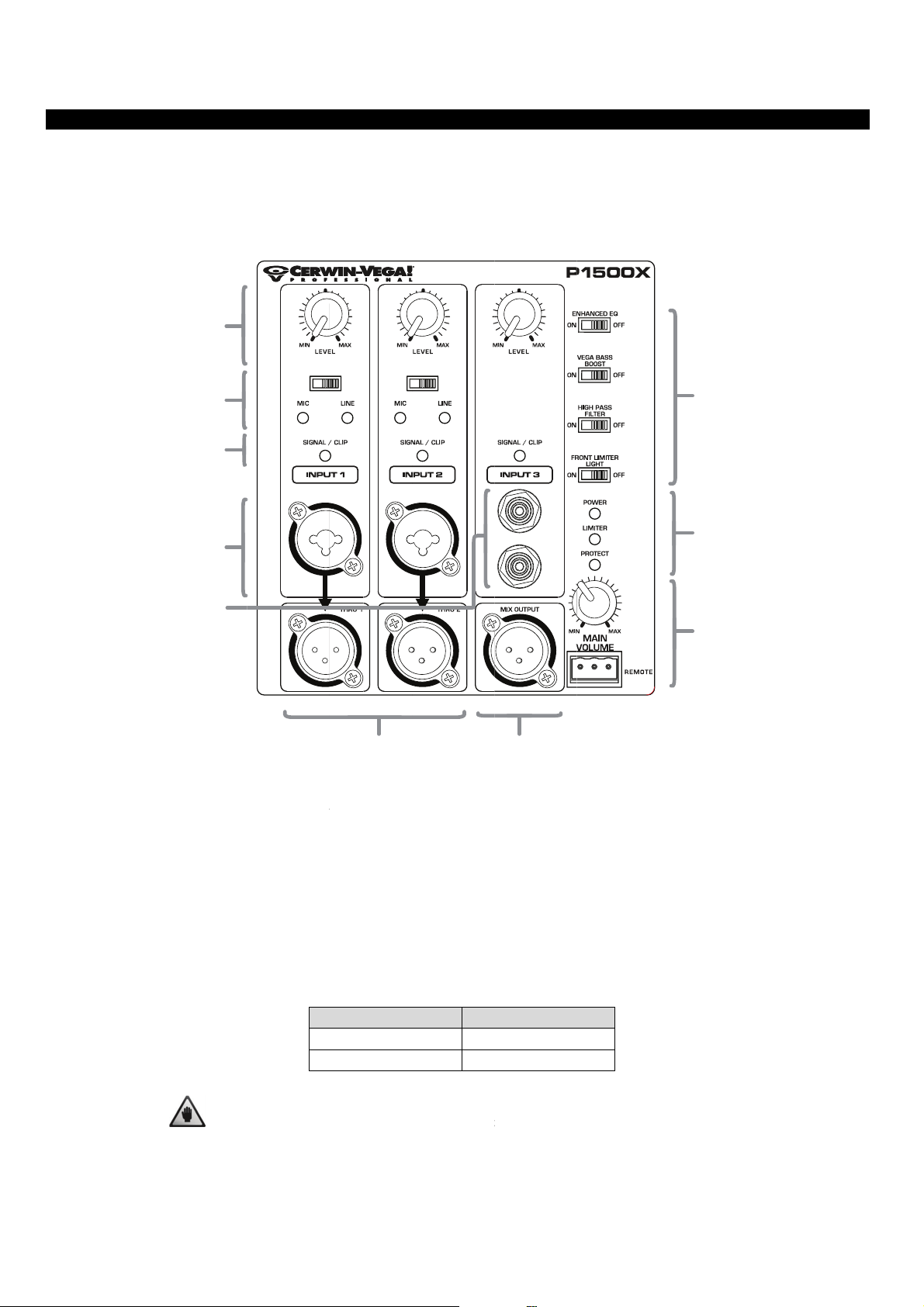
P1
00X an
The
P1000X and
ications. It i
appl
ures.
feat
P1500
P1500X po
suggested
A
Mixer -
ered louds
to review t
CERWIN
Rear Pa
eaker has
e P1000X/P
-VEGA! PROF
el
n assortme
500X mixe
ESSIONAL
t of mixer
, as listed b
ontrols and
low, to tak
connections
full advant
that cover
age of the p
everal
roduct
(A)
level knob
Eac
to
aximum w
rec
mmended t
cloc
wise positi
INPUT
B
C
D
E
, INPUT 2,
djusts the
ereas a full
o set each l
n when firs
INPUT 3 L
ain level on
counter-cl
vel knob t
connecting
F
EVEL KNO
the respecti
ckwise (MI
the middl
the system.
S
e input sig
) position
position a
al. The full c
ets the gai
d the main
lock-wise p
level to th
volume kno
J
I
H
sition (MAX
e minimum
b to the MI
sets the gai
‘MUTE’ lev
or fully c
n level
l. It is
unter-
(B)
Set
con
swit
INPUT
each switch
ected to IN
ch to ‘LINE’.
, INPUT 2
according
PUT 1, set t
NOT
inpu
MIC/LINE
o the equi
e switch to
E: The swit
t. Any mista
WITCH
ment conn
‘MIC’. If a
S
ITCH POSI
IC
LI
NE
h must be
e may resul
cted to IN
ixing cons
ION INP
2 k
40
roperly set
t in unexpec
8
UT 1 and I
le or acous
UT IMPEDA
hm
Ohm
to the devi
ted sound l
NPUT 2. Fo
ic-electric g
CE
e that is co
vel.
example,
itar is conn
nected to
f a microp
ected then
he
one is
et the
Page 9

CERWIN-VEGA! PROFESSIONAL
(C) SIGNAL/CLIP INDICATORS
Each of the three inputs is monitored by an indicator that provides status on the incoming audio signal. The SIGNAL
indicator is illuminated when there is an audio signal present with a level greater than -30dBu, approximately the lowest
level before a MUTE condition. The CLIP indicator is illuminated when the audio signal is clipping and adjustments must
be made to avoid amplifier shutdown and poor sound quality. Adjustments to prevent clipping are made by reducing the
input signal gain/level on the appropriate channel or reducing the volume level on your audio source, if possible.
(D) INPUT 1 & INPUT 2 INPUT JACKS
A combination input on each channel allows for either XLR or ¼” TRS cable types.
(E) INPUT 3 INPUT JACKS
A pair of ¼” TS unbalanced input jacks is provided on this channel for stereo connections such as a keyboard or media
device. Devices with RCA outputs can use these inputs with the appropriate cable or plug adapter. Both input jacks on
this channel are summed into one mono signal.
(F) THRU 1 & THRU 2
The balanced XLR outputs THRU 1 & THRU 2 are parallel connections to the respective INPUT 1 and INPUT 2. The level
controls for INPUT 1 & INPUT 2 will not affect the signal on the direct output connection.
(G) MIX OUTPUT
This is a balanced XLR output that is a sum of all three input channels. This output is not affected by changes to the
Main Volume knob or the custom features but is affected by the levels set on each channel level knob. This connection is
designed to provide an output which combines all three input channels together for connecting to another
P1000X/P1500X powered speaker or a recording device.
(H) MAIN VOLUME KNOB & REMOTE VOLUME CONTROL
It is highly recommended to have the volume set to the minimal (MIN) level upon initial system start-up and it can be
adjusted two different ways. On the main volume knob, volume is increased in a clockwise rotation and decreased in a
counter-clockwise rotation. Another method to control the volume is by using the Remote connection (sold separately).
A removable three-terminal jack can be wired over long distances to a remote volume control device with a
corresponding connection.
(I) INDICATORS
Three indicators provide operating condition status on the P1000X/P1500X:
1) The POWER indicator (green) will illuminate when power is properly applied to the P1000X/P1500X and the
main power switch is ‘ON’.
2) The LIMITER indicator (yellow) will illuminate when the P1000/P1500X automatically reduces the sound output
to prevent damage to the speaker. While the P1000X/P1500X is producing sound, it is suggested to reduce the
volume level so the LIMITER indicator does not illuminate. Continuing use of the P1000X/P1500X while this
indicator is illuminated may result in a protect condition where no sound can be produced.
3) The PROTECT indicator (red) will illuminate when the P1000X/P1500X automatically places itself into a condition
where sound output is shutoff. This condition may be the result of excessive limiting, an excessive heat
condition, or a low voltage condition. These conditions all can cause significant damage to the product.
9
Page 10

CERWIN-VEGA! PROFESSIONAL
(J) CUSTOM FEATURES
ENHANCED EQ SWITCH
The ENHANCED EQ switch adjusts the contour of the overall frequency response and attenuates the mid-range
frequencies which helps increase focus on the low and high frequencies while potentially reducing feedback. This
feature is ideal for situations where an external mixer or EQ device is not available or playback only situations such as
mobile DJ’s. It is recommended that users listen to their system with this switch both on or off to determine what is
best for their needs.
VEGA BASS BOOST SWITCH
Engaging the VEGA BASS BOOST switch to ‘ON’ adds low frequency gain to the signal and dynamically adjusts the lowfrequency response based on the speaker volume level. Leaving the switch ‘OFF’ and engaging the HIGH PASS FILTER is
recommended when using the P1000X/P1500X with a subwoofer. When using the P1000X/P1500X with the P1800X
subwoofer it is also recommended to engage the HPF THRU & LPF SUB switch on the P1800X for the best performance.
HIGH PASS FILTER SWITCH
When engaged to ‘ON’, the HIGH PASS FILTER (HPF) switch attenuates overall frequency output below 80Hz. This is
recommended to reduce stage rumble when the speaker is used as a floor monitor or in situations where low
frequencies need to be attenuated such as in combination with a subwoofer.
FRONT LIMITER LIGHT SWITCH
Setting the FRONT LIMITER LIGHT switch to ‘ON’ will enable the limiter indicator light on the front of the P1000X/P1500X.
This allows the user to see when the limiter is engaged in situations where it needs to be visible such as during a sound
check.
10
Page 11

CERWIN-VEGA! PROFESSIONAL
P1800SX Mixer - Rear Panel
The P1800SX powered subwoofer features an assortment of controls and connections similar to the P1000X/P1500X but
unique to the needs of this subwoofer. It is suggested to review the P1800SX mixer, as listed below, to take full
advantage of the product features.
(A) SIGNAL/CLIP INDICATOR
Each of the two inputs is monitored by an indicator that provides status on the incoming audio signal. The SIGNAL
indicator is illuminated when there is an audio signal present with a level greater than -30dB, approximately the lowest
level before a MUTE condition. The CLIP indicator is illuminated when the audio signal is clipping and adjustments must
be made to avoid amplifier shutdown and poor sound quality. Adjustments to prevent clipping are made by reducing the
input signal gain/level on the appropriate channel.
(B) INPUT 1 & INPUT 2 INPUT JACKS
A combination input allows for both XLR and ¼” TRS cable types.
(C) THRU 1 & THRU 2
The balanced XLR output is a connection to the respective INPUT 1 and INPUT 2. Note, the HPF THRU & LPF SUB custom
feature is placed between the INPUT and THRU.
11
Page 12

CERWIN-VEGA! PROFESSIONAL
(D) LINK OUTPUT
This is a balanced XLR output that is the sum of the two input channels. This output is not affected by changes to the
Main Volume knob or the custom features. This connection is designed to provide an output which combines both
channels together for connecting to an additional P1800SX.
(E) MAIN VOLUME KNOB & REMOTE VOLUME CONTROL
It is highly recommended to have the volume set to the minimal (MIN) level upon initial system start-up and it can be
adjusted two different ways. On the main volume knob, volume is increased in a clockwise rotation and decreased in a
counter-clockwise rotation. Another method to control the volume is by using the Remote connection (sold separately).
A removable three-terminal jack can be wired over long distances to a remote volume control device with a
corresponding connection.
(F) INDICATORS
Three indicators provide operating condition status on the P1800SX:
1) The POWER indicator (green) will illuminate when power is properly applied to the P1800SX and the main power
switch is ‘ON’.
2) The LIMITER indicator (yellow) will illuminate when the P1800SX automatically reduces the sound output to
prevent damage to the speaker. While the P1800SX is producing sound, it is suggested to reduce the volume
level so the LIMITER indicator does not illuminate. Continuing use of the P1800SX while this indicator is
illuminated may result in a protect condition where no sound can be produced.
3) The PROTECT indicator (red) will illuminate when the P1800SX automatically places itself into a condition where
sound output is shutoff. This condition may be the result of excessive limiting, an excessive heat condition, or a
low voltage condition. These conditions all can cause significant damage to the product.
(G) CUSTOM FEATURES
POLARITY REVERSE
In situations where the P1800SX is not optimally located, a polarity reverse switch is provided which inverts the phase of
the audio signal by 180 degrees and can improve low frequency performance. In certain situations, the location of the
subwoofer may be out of phase with the full-range speakers. By reversing the polarity of the subwoofer, the phase will
match the full-range with the benefit of not having to relocate the subwoofer.
VEGA BASS BOOST SWITCH
Engaging the VEGA BASS BOOST switch to ‘ON’ adds low frequency gain to the signal and dynamically adjusts the lowfrequency response based on the subwoofer volume level.
HPF THRU & LPF SUB
When turned on, the HPF THRU & LPF SUB switch engages two filters simultaneously:
1) A low pass filter will attenuate frequencies above 80Hz for the P1800SX subwoofer.
2) A high pass filter will attenuate frequencies below 80Hz on the THRU 1 & 2 outputs. This is recommended when
using the subwoofer in combination with other speakers such as the P1000X/P1500X.
FRONT LIMITER LIGHT
Setting the FRONT LIMITER LIGHT switch to ‘ON’ will enable the limiter indicator light on the front of the P1800SX. This
allows the user to see when the limiter is engaged in situations where it needs to be visible such as during a sound check.
12
Page 13

0
w
e
i
d
u
o
f
s
5
o
P
r
o
e
t
P
s
e
m
r
d
L
d
f
U
e
e
n
t
S
e
o
n
p
p
r
n
r
n
p
A
u
l
’
e
r
t
e
u
e
d
f
e
a
e
l
o
n
r
s
f
a
e
t
-
s
n
h
r
s
c
P1
The
P1000X, P1
er connecti
po
00X, P1
500X an
00X and P1
ns and desc
P1800
800SX pow
riptions bel
CERWIN
X Powe
r connectio
w to insure
-VEGA! PROF
Connec
s are locat
proper use.
ESSIONAL
ions - R
d on the re
ar Pane
r panel. It i
s suggested
to understa
nd the
(A)
The
loudspeake
t to the pr
is s
sett
ng, be sure
lou
speaker.
(B)
The
power inlet
ded with th
incl
Bel
w the powe
the
use with ra
(C)
ON/OFF ma
The
level befor
safe
(D)
fan is auto
The
hould neve
fan
MAIN
POWER
MAIN
FAN
OWER VO
can be use
per voltage
the proper
INLET & F
is an IEC r
loudspeak
r inlet is the
ed-equivale
OWER SWI
ter switch c
placing the
atically con
be blocked
TAGE SELE
with 100-1
before con
use has bee
SE
ceptacle ty
r.
fuse holder
t (see Speci
TCH
ontrols the
loudspeake
rolled by th
in order to i
CTOR
20V AC or 2
ecting the
n installed.
e and sho
that can on
fication sect
ower to the
into an ‘ON
e loudspeak
sure prope
20-240V AC
ower cord.
ny failure t
ld only be
y be access
ion).
loudspeake
condition.
r and provi
cooling air
power supp
In addition,
o meet thes
sed with th
d when the
r. Be sure all
es air-flow
low to the
ly lines. Be s
if the select
e instructio
e power co
power cord
connection
ventilation
lectronics.
ure the volt
r is adjust
s may resul
d, or rated
is removed.
and audio
or the inter
ge selector
d from its s
in damage
equivalent,
Be sure to
ettings are
al electroni
switch
ipped
to the
that is
eplace
et at a
s. The
13
Page 14

i
a
0
i
a
t
1
d
o
b
h
o
s
H
n
n
g
a
a
n
T
T
º
0
s
e
r
t
p
0
p
k
o
o
e
w
h
v
c
c
h
e
y
P
o
n
u
o
a
St
S
w
a
i
e
s
w
t
i
o
g
t
e
a
a
s
s
e
i
h
o
n
Us
ng the P
The
P1000X an
rd the perf
tow
low
frequency
0X/P1500X
P10
angl
e XLR or rig
000X a
P1500X ca
rmers. It is
ass-couplin
and cables
t angle ¼” j
d P150
be used a
recommend
or stage
re not loca
cks where
CERWIN
X as a fl
s a floor m
d to engag
umble bet
ed where t
ossible to a
-VEGA! PROF
or/stag
nitor by la
the HIGH
een the lo
ey can bec
oid cable bi
ESSIONAL
monito
ing the cabi
ASS FILTER
udspeaker
me a tripp
ding betwe
r
net on its s
hich cuts l
nd the sta
ng hazard. I
n the louds
de at a fixe
w frequenci
e platform.
is recomm
peaker and
d 45 degre
es to minim
Be sure t
ended to us
tage platfor
angle
ze any
at the
e right
m.
Us
ng the p
The
P1000X feat
pole. To u
on
Nex
, spin the S
le mou
ures a SHAF
e the SHAF
AFT GRABB
t – P10
GRABBER
GRABBER,
ER disc cloc
45
0X only
ole mount
spin the dis
wise until t
up that red
counter-cl
e speaker h
ces unnece
ckwise unti
s a tight fit
peaker direc
age Floor
sary wobbl
l the pole c
ith the spe
ion
when the
n fit into th
ker pole.
peaker is m
e pole mou
unted
t cup.
14
Page 15

i
w
u
u
t
t
.
o
s
l
d
o
w
N
u
o
h
r
e
r
i
d
s
n
e
e
i
e
n
o
i
u
c
a
k
e
r
a
p
i
,
o
d
0
o
a
e
u
h
s
e
d
h
h
s
n
a
d
n
a
a
a
g
e
e
t
o
e
p
h
e
r
k
d
e
e
t
d
o
m
l
d
c
e
e
b
p
n
d
a
a
g
o
u
e
h
a
e
e
f
w
.
w
o
t
o
h
g
h
e
w
c
c
t
u
r
e
t
e
e
r
e
a
a
n
Us
ng the p
The
P1500X ha
s the louds
allo
For
example, a
sted to 7.5
adj
Adj
st the pole
bot
om of the l
the
wo tabs to
or 7
5 (angle do
le mou
two differ
peaker to b
oudspeaker
egrees dow
mount angl
udspeaker
rotate the d
nwards). B
– P15
nt pole m
adjusted to
placed on
nward so th
e on the lo
s a rotatabl
isc so that t
sure the di
CERWIN
0X only
unting angl
an angle th
raised sta
front audi
dspeaker b
e disc with
e position i
c ‘clicks’ int
-VEGA! PROF
es: level an
t provides
e platform
nce will not
fore it is p
wo tabs an
ndicator is a
place and
ESSIONAL
d 7.5 degre
ptimal audi
may have t
be missed.
aced onto
a position
ligned with
annot rotat
es down. T
nce covera
e pole mou
pole. On t
indicator. U
ither 0 (lev
freely.
is
e.
nt
se
e
l)
7.5
0
CAUTIO
Make
preca
The p
legs s
Powe
or top
When
Befor
and/o
Only u
Avoid
In a w
for ad
Consu
nation
under
: When usi
sure the p
tions as ind
le stand m
ould be pla
cables and
ple the spea
placing the l
loudspeak
missing pa
se a pole st
placing the
ndy environ
itional stab
lt a licensed
al regulati
tood and a
g stands or
le stand is
cated by th
st be place
ed where t
udio signal
ers over w
oudspeaker
r pole mou
ts that may
nd intende
ole stand a
ment, be su
lity. Do not
profession
ns regardin
hered to.
poles, be su
capable of
pole stand
on a flat, l
ey will not
cables must
en moved o
on top of t
ting, be sur
ffect the st
for loudspe
d loudspea
re to use ad
ttach bann
l engineer r
g the safe
re to observ
handling th
manufactur
vel and sta
resent a tri
be placed i
r pulled.
e pole stan
to inspect
ength and s
aker use.
er in an are
itional wei
rs, signage
garding eq
y and ope
the followi
e weight o
r.
le surface
ping hazard
a location
, be sure to
ll critical po
afety of the
of traffic t
ht to suppo
r balloons t
ipment ins
ration of l
ng:
the loudsp
ith the legs
here they
ask for help
ints for any
installation.
prevent ac
rt (sandbags
o the pole s
allation and
udspeakers
eaker. Be s
fully extend
ill not creat
.
racks, defo
idental cont
) on the bas
and and/or
ensure that
and relat
ure to obse
ed. The pol
e a tripping
mations, co
act.
of the pol
he loudspe
all local, st
d equipme
rve all
stand
hazard
rosion
stand
ker.
te and
t are
15
Page 16

i
h
t
d
t
d
z
h
u
d
2
r
,
t
N
p
e
s
t
e
r
u
e
h
n
u
d
d
u
o
o
n
e
o
,
o
d
e
r
c
.
g
s
n
g
o
a
d
s
o
r
a
e
n
a
b
m
r
e
n
n
u
e
t
o
r
d
a
f
p
w
s
u
n
e
o
t
y
e
a
e
t
o
n
d
g
u
o
n
a
h
u
f
e
n
n
u
p
e
a
n
r
o
n
n
Us
ng the s
The
P1000X an
a depth of
wit
spensio
P1500X s
5mm.
n points
spension p
CERWIN
ints are M
-VEGA! PROF
10 threads
ESSIONAL
On
he P1000X,
han
le with fou
On
he P1500X
han
le (top fo
hori
ontal orien
on t
he rear of th
CAUTIO
Louds
unsaf
Consu
nation
under
Do no
Befor
and/o
Only
for th
Fitting
sure t
Cerwi
struct
two suspen
pull-back p
two suspe
r vertical
ation) as w
e unit.
: When usi
eaker susp
mounting
lt a licensed
al regulati
tood and a
attempt to
loudspeak
missing pa
se commer
actual load
s and riggin
e installed i
-Vega! can
re or impro
sion points
ints locate
nsion point
rientation
ell as two p
g suspensi
nsion requi
f any heavy
profession
ns regardin
hered to.
suspend th
r suspensio
ts that may
ially-availa
hardware
checked th
ot be held
per installati
re located
on the rear
are locate
and on th
ull-back poi
n installatio
es qualified
load can res
l engineer r
g the safe
loudspeake
, be sure t
ffect the st
le M10 loa
ay deterior
oroughly by
esponsible
on.
on the top
of the unit.
d on each
side for
ts located
, be sure to
persons wh
lt in seriou
garding eq
y and ope
rs by the ha
inspect all
ength and s
-rated shou
te over ext
qualified pe
or damage
observe th
o are famili
injury and
ipment ins
ration of l
dles.
critical poi
afety of the
lder eyebolt
nded perio
rsonal at re
r injury ca
following:
r with riggi
quipment d
allation and
udspeakers
ts for any c
installation.
s along wit
s of time d
ular interval
sed by insu
g standards
amage.
ensure that
and relat
racks, defor
rigging har
e to wear a
s.
ficient stre
and practic
all local, st
d equipme
mations, co
dware appr
d/or corros
gth of the s
s. Any
te and
t are
rosion
priate
ion, be
upport
Do not
intende
intende
use the pull
for anglin
for one lou
-back point
the louds
dspeaker on
as the sus
peaker do
ly.
ension poin
nwards onl
16
t for a maj
. Note tha
rity of the
t the louds
load. The p
peaker sus
ll-back poi
ension poi
ts are
ts are
Page 17

p
n
d
n
u
u
u
v
#
s
e
o
q
c
M
e
t
e
p
t
t
S
m
P
o
e
h
u
e
o
r
p
X
e
i
e
e
C
¼XD
n
u
a
e
u
a
b
t
t
e
o
h
Ap
lication
A si
gle P1000X
diag
ram below
ia player ar
me
mai
volume kn
1 – Singl
or P1500X
hows an a
used toge
b controls t
P1000X
powered sp
plication w
her. Each in
he overall a
CERWIN
r P1500
aker can b
ere a vocal
dividual cha
dience volu
-VEGA! PROF
used to re
microphon
nnel volum
me.
ESSIONAL
inforce sou
, an acoust
can be adj
d for a wid
ic-electric g
sted to cre
variety of
itar and ei
te the righ
performanc
her a keyb
balance w
s. The
ard or
ile the
t 1 A
Inp
Inp
t 2
Inp
t 3 K
De
ices with RCA ou
*
E
uipment
oustic-Elec
icrophone (
yboard (or
puts can use IN
ric Guitar (S
et switch t
edia playe
UT 3 with the ap
t switch to
MIC)
)
ropriate cable o
LINE)
r plug adapters.
17
able Type
” TS (stand
LR
ual ¼” TS (o
rd guitar ca
r RCA*)
le)
Page 18

p
t
a
#
X
t
d
n
e
n
m
n
r
u
X
r
X
b
0
n
w
m
d
v
U
o
a
T
a
p
e
d
e
v
n
e
P
e
h
n
Ap
lication
A se
cond P1000
speaker sys
two
1500X louds
or P
he level an
set
spe
ker will not
simi
lar settings.
2 – Addi
or P1500X
em can cov
peaker, con
main volu
change the
g a seco
loudspeake
r a wider a
ect the MI
e to an app
volume on
CERWIN
d P1000
can easily
dience and
OUTPUT of
opriate sett
the second
-VEGA! PROF
or P150
e added usi
situations
the first spe
ing on the fi
speaker so
ESSIONAL
X
g a standar
here more
aker to INP
rst speaker.
ake sure t
XLR/mic c
olume is ne
T 1 or INPU
Be aware th
set the in
ble as in th
eded. To ad
2 on the s
t the main
ut and mai
example b
a second
cond speak
olume on t
volume k
low. A
1000X
r then
e first
obs to
18
Page 19

CERWIN-VEGA! PROFESSIONAL
Application #3 – Adding Subwoofers
For demanding applications where even greater bass response is ideal, adding subwoofers to a pair of P1000X/P1500X
speakers is a great idea. In the diagram below, an audio source is connected to INPUT 1 on each P1800SX subwoofer
and then the signal is linked to the P1000X/P1500X speakers by using the P1800SX THRU 1 outputs. The P1000X/P1500X
and P1800SX also have CUSTOM FEATURES that allow them to work together efficiently which is covered on the next
page.
AUDIO SOURCE
P1500X Equipment Cable Type
Input 1 From P1800SX THRU 1 output XLR
P1800SX Equipment Cable Type
Input 1 From Audio Source XLR or ¼” TRS
19
Page 20

p
e
0
O
#
P
s
d
D
m
n
5
t
i
a
e
o
8
R
o
e
O
0
0
p
a
h
B
s
X
s
L
0
a
P
o
t
t
e
O
N
N
X
r
O
i
o
X
o
f
GBO
0P18
S
t
e
t
0
X
T
b
P
w
P
S
a
g
0
1
Ap
lication
Wh
n using the
on t
he P1000X/
unately, thi
Fort
0SX depen
P18
3 – Addi
P1000X/P1
1500X and
system is
ing on the s
g Subwo
00X and P1
he HPF TH
designed s
ituation. Th
CERWIN
fers (Adj
00SX toget
U & LPF SU
that the u
settings bel
-VEGA! PROF
usting H
er it is imp
switch on
ser can rou
ow have be
ESSIONAL
F & LPF F
rtant to kn
he P1800S
e the audi
n provided
lters con
w how to s
so that bot
source to
or either se
inued)
t the HIGH
h speakers
either the
up.
ASS FILTER
ork well to
1000X/P15
switch
ether.
0X or
SIGNAL FL
TOP (P1
(P1800SX)
W
00X/P1500
) to B
AUDIO S
TTOM
SI
NAL FLOW
TTOM (P18
0SX) to TOP
(P1000X/ P
500X)
REC
MMENDE
NOTE: U
comple
SETTINGS
sing a stand
entary syst
P1000X/15
P1800SX: H
rd speaker
m that is e
0X: High Pa
PF THRU &
ole, the P1
sy to setup
ss Filter is O
PF SUB is O
00X/P1500
nd transpo
20
and P1800
t.
P1
00X/P1500
00SX: HPF
X active su
: High Pass
HRU & LPF
woofer cre
Filter is OFF
UB is ON
te a
Page 21

CERWIN-VEGA! PROFESSIONAL
Application #4 – Daisy-Chain
Some events may require several P1000X/P1500X speakers spread across a long distance or a large stage front to
provide adequate sound reinforcement for the entire audience. Since there are multiple sources, the loop out from the
mix output should be used to daisy-chain to the next P1000X/P1500X and then use the thru-out from the second
speaker onward.
Equipment Cable Type
Input 1 Microphone (Set switch to MIC) XLR
Input 2 Microphone (Set switch to MIC) XLR
Input 3 Player (Left-to-Left, Right-to-Right) ⅛” to dual ¼” TS( or RCA*)
MIX
OUTPUT
* Devices with RCA outputs can use INPUT 3 with the appropriate cable or plug adapters.
P1000X/P1500X next in daisy-chain
(Input 1, Set switch to LINE)
XLR
21
Page 22

p
smea
n
#
m
s
f
H
e
m
C
n
p
n
t
a
0
m
p
r
s
h
n
0
t
)
m
d
e
S
g
a
n
f
w
r
e
n
t
r
m
e
t
d
r
s
m
t
e
o
h
m
X
h
e
e
t
k
e
p
n
o
Ap
lication
In a
live perfor
ram below
diag
y-chained)
(dai
ns all the T
the
first loudsp
itor can be
mo
5 – Addi
ance, the
hows a P10
or the audi
RU outputs
aker, the i
ixed to the
g a P100
performer
00X/P1500X
ence. The
from the pe
put levels c
performer’
CERWIN
X or P15
ay wish to
used as a s
erformer(s
former(s)
an be mixe
specific req
-VEGA! PROF
0X as a
have a sta
age monito
may have
ust be take
to the pre
uirements
ESSIONAL
tage Mo
e monitor
r for the pe
a different
to the first
erred pres
ithout affec
itor
o help hea
former plu
ix require
loudspeaker
ntation for
ing what th
the perfor
two P1000
ent than t
used to cov
he audienc
audience h
ance bett
/P1500X s
e audience
r the audie
. The perf
ears
r. The
eakers
which
ce. At
rmer’s
NOTE:
suscepti
areful posi
ble to feedb
ioning of t
ck. As a ge
e monitor
eral rule, n
loudspeake
ver point th
is require
microphon
as the pr
e towards t
ximity to
e loudspea
he microph
er.
one is
22
Page 23

CERWIN-VEGA! PROFESSIONAL
Application #6 – Large Venue/Front of House
In larger venues the Front of House engineer has control of the entire sound reinforcement system using the console
mixer. The diagram below shows how a console mixer interfaces with the performers’ on-stage audio equipment with
several P1000X/P1500X speakers directed towards the audience.
23
Page 24

o
hRem
e
m
o
o
G
5
a
c
i
n
u
t
n
8
n
a
t
m
o
n
n
e
h
e
n
w
d
n
s
t
t
s
k
0
a
o
t
t
s
d
v
e
o
o
u
v
k
e
s
h
m
o
t
d
e
e
e
w
q
h
i
n
e
e
o
o
h
m
a
c
a
f
r
Pr
tective
The
P1000X, P1
prevent any
will
rill
00X and P1
accidental d
00SX are s
amage to th
CERWIN
ipped with
drivers tha
-VEGA! PROF
he grill atta
t may result
ESSIONAL
ched. It is r
during tran
commende
portation, s
to leave th
tup and ge
e grill in pla
eral use.
e as it
e event th
In t
ove the gril
fast
ners are se
Re
ote Ma
The
3-pin termi
ote location
rem
and
not the act
potentiome
The
First Lo
t the grill
l slowly to
ured in tigh
n Volu
al connect
through sig
al audio sig
er should b
NOT
volu
resu
udspeaker
eeds to be
void damag
ly to preve
e
r plug allo
al wires an
al. A single
10kOhm a
E: Do not u
me control
lt in damage
removed,
ing the gas
t rattling du
s the P100
d an extern
evice can c
d specified
e the remo
hrough the
to the loud
Secon
imply remo
et. When r
ring general
X, P1500X
l device (n
ntrol the m
o support n
e main volu
external de
peaker.
Loudspea
e the hex-
placing the
use.
r P1800SX
t included).
ain volume
merous rot
me connecti
ice. Failure
ead screws
grill, be sur
ain volum
The signal
f multiple u
ations as re
on for anyt
o follow th
Third Lo
around th
the gasket
level to b
ire passes
nits when c
uired for vo
ing other t
s warning
udspeaker
edge of th
is in place
controlled
nly a voltag
nnected co
lume contro
an
ay
nd on...
e grill.
nd all
rom a
e level
rectly.
l use.
ccw w
V
lume Pote
cw
tiometer
24
Page 25

s
s
c
c
a
a
0
0
1
w
Sy
tem Blo
k Diagr
m (P10
CERWIN
0X and
-VEGA! PROF
500X fu
ESSIONAL
ll-range loudspeaker)
Sy
tem Blo
k Diagr
m (P18
0SX sub
oofer)
25
Page 26

CERWIN-VEGA! PROFESSIONAL
Troubleshooting
Problem
No Sound Loudspeaker is not
Loudspeaker power
Input level is set to
Main volume is set to
Audio source is not
No Power Loudspeaker is not
Loudspeaker power
AC power source
Loudspeaker fuse is
Shutdown Loudspeaker self-
Cause
connected to active
AC power
switch is in the ‘OFF’
position
minimum setting
minimum setting
active, volume is set
too low, or poor
connection
connected to active
AC power
switch is in the ‘OFF’
position
voltage is too low or
high
blown
protection
Solution
Verify the loudspeaker is indeed connected to an active AC power source.
Various outlets may need to be switched ‘on’. Use a lamp as another way to be
sure the AC power source is active.
Verify that the power switch on the back of the loudspeaker is ‘ON’.
Set the input level to a setting where sound can be heard.
Set the volume level to a setting where sound can be heard.
Use the Signal indicator on the back of the loudspeaker to verify an audio
signal is indeed present.
Verify that the audio equipment is turned ‘ON’ and set to output an audio
signal at a volume level above minimum.
Verify the cable connection from the audio source output to the loudspeaker
input is correct.
Audio mixers may have a MUTE or LOOP switch that may need to be
disengaged.
Microphones that require phantom power must be used with an external
power source.
Verify the loudspeaker is indeed connected to an active AC power source.
Various outlets may need to be switched ‘ON’. Use a lamp as another way to be
sure the AC power source is active.
Verify that the power switch on the back of the loudspeaker is ‘ON’.
Verify if the AC power source is too low or too high. The loudspeaker will
protect itself if the AC power source is 10% lower or 10% higher than the
loudspeaker’s intended voltage setting.
Disconnect all power connections and inspect and replace, if necessary, the
fuse located on the rear of the loudspeaker. See Specifications for fuse
information.
Avoid placing the loudspeaker near a heat source or under direct sun light.
Avoid using an audio source with clipped and/or distorted input signal.
Verify the limiter indicators are not always on and if so, lower the input and
volume levels until the limiter indicator is ‘OFF’.
26
Page 27

Troubleshooting (continued)
CERWIN-VEGA! PROFESSIONAL
Bad Sound Equipment settings
are not set properly
causing distortion
Bad cable connections Verify that all connections are good. Verify the connectors are clean and free of
Rattling Sounds Be sure the rattling sounds do not come from the caster wheels (subwoofer
Bad AC mains cable
location
Ground loop ‘hum’ Turn all volume and input levels to the minimum setting to verify there is no
Equipment ‘hiss’ Use a balanced connection (instead of an unbalanced connection) to take
Check the meters on the external mixing console to ensure that the signal is
not being clipped by the mixer, if the levels from the mixer are too hot
correct the gain structure of the console; first by lowering the pre-amplifier
trim (input sensitivity), if this does not lower the signal level sufficiently then
lower the channel fader, and if the level is still too hot then lower the master
bus (but most likely a clipped input is the source of the distortion). It is
important to check every active input channel on the console to ensure that
each input trim is set correctly for each source.
If the signal sources are plugged directly into the P1000X/P1500X make sure
that the input level knobs are not turned up too high. If the signal indicator
LED is turning RED on any channel that means the input on that channel is
clipping and the input level needs to be lowered. It is also possible that the
source level will need to be lowered. If distortion is still audible after
lowering the source level and input level knob then lower the master volume
knob on the P1500X.
Check that the audio source and/or mixer do not have excessive bass or
treble added to the mix, overdriven EQ’s can clip causing audible distortion.
any residue build-up. Verify the insulation jacket on all cables has not been torn
or crushed.
only), loudspeaker stands or any furniture or fixtures located near the system.
Avoid using an AC power source that is connected to a light dimmer. Use an AC
filter box or use a different AC circuit.
Avoid routing the audio signal cables along other power cables, transformers
and signal cables to prevent interference.
‘hum’ coming from the connected audio equipment. If the ‘hum’ is still present,
than remove all audio cable connections and if the ‘hum’ disappears than there
is a potential ground loop problem. Ground lifting the signal cable (with a direct
box or coupling transformer) is the safest way to eliminate ground loops within
sound setups. Plug all audio equipment AC power connections into the same
outlet which shares a common ground (make sure the outlet is capable of
supporting the equipment to avoid overloading the circuit). Verify that the
distance between AC power source and common ground is as short as possible.
advantage of the best noise rejection.
Plug all audio equipment AC power connections into the same outlet which
shares a common ground (make sure the outlet is capable of supporting the
equipment to avoid overloading the circuit).
27
Page 28

CERWIN-VEGA! PROFESSIONAL
Care and Maintenance
Before any cleaning or maintenance, be sure the loudspeaker is unplugged, turned off, and that all cables are removed.
Be sure to avoid any moisture coming into the openings of the speaker.
The loudspeaker can be maintained cosmetically using a dry cloth. Avoid using cleaning chemicals as they may harm the
finish of the loudspeaker. A direct burst of air should be avoided and may harm the drivers as well as assisting debris
into the enclosure.
When storing the loudspeaker, be sure it is above ground to avoid accidental flooding and excess dust build-up. It is
suggested to cover the loudspeaker while it is placed in storage or being transported.
Appendix A – Cable Connections
1/4” TRS
Balanced
Hot (positive)
Cold (negative)
Shield
Sleeve
Hot (positive)
Cold (negative)
XLR Balanced Input
Ring
Tip
Sleeve
Ring
Shield
Tip
Hot (
Cold (
Shield
positive
negative
2
3
1
)
)
1/4” TS
Unbalanced
28
Sleeve
Tip
TipSleeve
Signal
Ground
Page 29

CERWIN-VEGA! PROFESSIONAL
REMOTE DEVICE REMOTE SIDE OF CABLE
DESCRIPTION CABLE (Connector Type)
A. XLR**
Floating or Balanced
low impedance: most
professional equipment
line in and line out,
microphones.
B. TRS PHONE
Unbalanced
low impedance: some
C. STANDARD
PHONE
professional equipment
and microphones.
2
3
1
TRS
TS
Hot (positive)
Shield/GND
Hot (positive) Cold (negative)
Shield/GND
Hot (positive) Cold (negative)
Shield/GND
Cold (negative)
2
3
(XLR)
1
2
3
(XLR)
1
2
3
(XLR)
1
D. STANDARD
PHONE
Unbalanced
high impedance: most
hi-fi equipment.
Unbalanced
E. SHIELD/GND
PHONE
high impedance: most
hi-fi equipment.
TS
T TSS
Hot (positive) Cold (negative)
Shield/GND
Hot (positive)
Shield/GND
29
2
3
(XLR)
1
(Standard Phone)
Page 30

CERWIN-VEGA! PROFESSIONAL
Warranty
Thank you for choosing one of Gibson Pro Audio’s brands (Stanton, KRK, or Cerwin Vega!).
Your satisfaction is extremely important to us. We proudly stand behind the quality of our work and appreciate that you
put your trust in us. Registering your merchandise will help us guarantee that you are kept up to date on our latest
advances.
To Register Merchandise Purchased from an Authorized Gibson Pro Audio Dealer in the U.S.:
Please go to: http://www.gibson.com and register online.
Or you may send your warranty card to:
Gibson Customer Service
309 Plus Park Blvd.
Nashville, TN 37217
If you have any questions you may contact customer service at:
1-800-4GIBSON (1-800-444-2766)
e-mail: service@gibson.com
FOR MERCHANDISE PURCHASED FROM AN AUTHORIZED GIBSON PRO AUDIO DISTRIBUTOR OUTSIDE OF THE US, PLEASE
CONTACT THE DISTRIBUTOR FROM WHOM YOU PURCHASED YOUR MERCHANDISE FOR TO REGISTER YOUR WARRANTY
AND FOR HANDLING AND RESOLUTION OF ALL WARRANTY-RELATED ISSUES.
Gibson Pro Audio Warranty
If at any time your Gibson Pro Audio product (which includes Stanton, KRK, or Cerwin Vega! brands) malfunctions as a
result of faulty materials or workmanship, Gibson Pro Audio or one of Gibson Pro Audio’s Authorized Service Centers in
the US will repair the defect(s) or replace the merchandise, as it deems appropriate at its sole discretion.
Warranty Period (from date of Purchase as listed on the Bill of Sale):
Stanton
One (1) year for all Stanton products.
KRK
Three (3) years from all studio monitors.
One (1) year all headphones, computer audio devices, including room correction devices.
Cerwin Vega!
Five (5) years for all passive speaker systems.
Three (3) years for all active speaker systems.
Three (3) years for all mixers.
Gibson will warrant all replacement parts and repairs for ninety (90) days from the date of original shipment.
In the unlikely event that your merchandise is destroyed, lost or damaged beyond repair while in the possession of
Gibson or one of Gibson Pro Audio’s Authorized Service Centers for repair, Gibson will replace that merchandise with
one of the same or most similar style of a value not in excess of the original purchase price of your merchandise. Any
insurance covering the merchandise, including but not limited to collector's value insurance, must be carried by owner
at owner's expense.
For the fastest and safest merchandise return, please use the original shipping carton and packaging materials. Gibson
cannot be responsible for any damages incurred during the shipping process due to poor or inadequate packing.
30
Page 31

CERWIN-VEGA! PROFESSIONAL
THIS WARRANTY IS EXTENDED TO THE ORIGINAL RETAIL PURCHASER ONLY AND MAY NOT BE TRANSFERRED OR
ASSIGNED TO SUBSEQUENT OWNERS. IN ORDER TO VALIDATE YOUR WARRANTY, AND AS A CONDITION PRECEDENT TO
WARRANTY COVERAGE HEREUNDER, YOU MUST REGISTER YOUR WARRANTY WITHIN FIFTEEN (15) DAYS FOLLOWING
THE ORIGINAL DATE OF PURCHASE.YOUR PROOF OF PURCHASE OR SALES RECEIPT MUST ACCOMPANY ALL REQUESTS
FOR WARRANTY COVERAGE.
This warranty is subject to the following limitations:
THIS WARRANTY DOES NOT COVER
1. Any merchandise that has been altered or modified in any way or upon which the serial number has been tampered
with or altered.
2. Any merchandise whose warranty card has been altered or upon which false information has been given.
3. Any merchandise that has been damaged due to misuse, negligence, or improper operation.
4. Any merchandise that has been damaged by accident, flood, fire, lightening, or other acts of God.
5. Shipping damage of any kind.
6. Any merchandise that has been subjected to extremes of humidity or temperature.
7. Any merchandise that has been purchased from an unauthorized dealer, or upon which unauthorized repair or service
has been performed.
GIBSON MAKES NO OTHER EXPRESS WARRANTY OF ANY KIND WHATSOEVER. ALL IMPLIED WARRANTIES, INCLUDING
WARRANTIES OF MERCHANTABILITY AND FITNESS FOR A PARTICULAR PURPOSE, EXCEEDING THE SPECIFIC PROVISIONS
OF THIS WARRANTY ARE HEREBY DISCLAIMED AND EXCLUDED FROM THIS WARRANTY. SOME STATES AND/OR
COUNTRIES DO NOT ALLOW THE EXCLUSION OR LIMITATION OF IMPLIED WARRANTIES SO THAT THE ABOVE MAY NOT
APPLY TO YOU.
GIBSON SHALL NOT BE LIABLE FOR ANY SPECIAL, INDIRECT CONSEQUENTIAL, INCIDENTAL OR OTHER SIMILAR DAMAGES
SUFFERED BY THE PURCHASER OR ANY THIRD PARTY, INCLUDING WITHOUT LIMITATION, DAMAGES FOR LOSS OF
PROFITS OR BUSINESS OR DAMAGES RESULTING FROM USE OR PERFORMANCE OF THE MERCHANDISE, WHETHER IN
CONTRACT OR IN TORT, EVEN IF GIBSON OR ITS AUTHORIZED REPRESENTATIVE HAS BEEN ADVISED OF THE POSSIBILITY
OF SUCH DAMAGES, AND GIBSON SHALL NOT BE LIABLE FOR ANY EXPENSES, CLAIMS, OR SUITS ARISING OUT OF OR
RELATING TO ANY OF THE FOREGOING.
FOR MERCHANDISE PURCHASED FROM AN AUTHORIZED GIBSON PRO AUDIO DISTRIBUTOR OUTSIDE OF THE US, PLEASE
CONTACT THE DISTRIBUTOR FROM WHOM YOU PURCHASED YOUR MERCHANDISE FOR THE HANDLING AND
RESOLUTION OF ALL WARRANTY ISSUES. FOR THESE PURCHASES, THE ABOVE-DESCRIBED WARRANTY IS NOT
APPLICABLE.
31
Page 32

CERWIN-VEGA! PROFESSIONAL
How to Obtain Warranty Service
Warranty Service outside the United States:
To initiate a warranty repair, please contact the Authorized Gibson Pro Audio distributor from whom you purchased
your merchandise, and follow the distributor’s return/warranty policy.
Warranty Service for Merchandise Purchased from an Authorized Gibson Pro Audio Dealer in the U.S:
In the event of malfunction of your Gibson Pro Audio merchandise, the Dealer or Owner must call Customer Service @
1-800-4GIBSON (1-800-444-2766) and obtain a Return Authorization number from the customer service agent. No
merchandise may be returned to Gibson without such prior Return Authorization, and the Return Authorization number
must be written on the outside of the shipping package. The Customer Service agent will provide the address and
additional shipping instructions. Owner must ship the merchandise, freight, and insurance pre-paid to the address
provided by the customer service representative. Only Authorized Gibson Pro Audio Service Centers may perform
warranty service and any service performed by unauthorized persons will void this warranty. Gibson disclaims liability
for defects or damage caused by services performed by unauthorized persons or non-warranty service not performed by
Gibson or an Authorized Gibson Pro Audio Service Center.
When contacting Gibson, you must include a complete written description of the malfunction of the merchandise. If
non-warranty work is required or recommended, a quotation will be issued and must be approved by you before any
non-warranty work is commenced. You should consider quotations obtained for non-warranty work immediately and
advise the Authorized Gibson Pro Audio Service Center or Gibson of your wishes. You are not required to purchase nonwarranty work in order to obtain service on materials covered by this warranty. Following its inspection of merchandise
upon its arrival, Gibson or the Authorized Gibson Pro Audio Service Center will advise you or your dealer of the
approximate date of completion. The repaired merchandise or part will be returned to you or your dealer, freight collect
insured.
No representative or other person is authorized to assume for Gibson any liability except as stated in this warranty. This
warranty gives you specific rights which vary from state to state or from country to country.
For further information, write:
Customer Service Dept.,
Gibson Customer Service
309 Plus Park Blvd.
Nashville, TN 37217
Or call:
1-800-4GIBSON
32
 Loading...