

Page 1
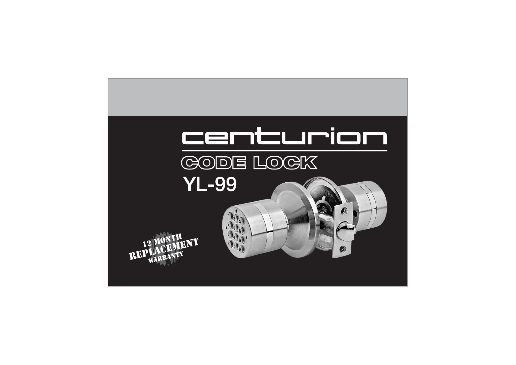
Programming and Installation Instructions
TM
Passed ISO9001-2000 international system ratification
Page 2
FEATURES
ACCESS CODE INSTRUCTIONS
The YL-99 electronic lock is capable of storing up to 10 access
codes; 1 Master code, 1 Passage code and 8 User codes.
All codes are allocated a starting number or sequence
number. The master code is ‘0’, the passage code is ‘9’ and
the user codes are ‘1-8’.
The master code must be set up in order to input user codes.
• Waterproof seals protecting electronic
components
• Backlit keypad for use in low light
• Up to 10 changeable codes including
passage, user and master levels
• Deadlatch assembly with adjustable
backset
• DIY installation (instructions included)
• LED indicators for code entry
• 50 event audit trail recording
• Anti spy code encryption
• Low battery warning with emergency
power jump override
1
MASTER CODE
The master code is the most important code in the series as it
is needed to set up all user codes and the passage code.
All codes can be a maximum of 15 digits including the
allocated sequence number.
The allocated sequence number for the master code is ‘0’,
therefore you must ensure this is the first digit of your code
and the remainder may be any combination of digits from
‘0-9’.
The manufacturers default code is ‘0123’.
To unlock the lock, enter the code ‘0123’ and press the ‘#’
key. The lock will sound and the green indicator will light. The
handle is unlocked while the beep is sounding and will return
to the locked position once the beep stops.
Page 3

CHANGING THE MASTER CODE
USER CODES AND PASSAGE CODES
Step 1.
Enter the default master code (‘0123’) or the current
master code, and press the ‘#’ key.
Step 2.
Wait until the beeping sound stops but the blue backlight
remains on.
Step 3.
Enter a new master code that starts with ‘0’ and press the
‘*’ key.
If two beeps are heard the new master code has been
saved successfully.
Note: Door should always be ajar when adding /
changing codes.
RESETTING THE MASTER CODE
The reset button is located on the battery pack and
should only be used when the master code is lost or
forgotten. Press and hold the reset button for five
seconds until three beeps are heard. The master code
will return to the manufacturer default code ‘0123’.
The user and passage codes can be any number and
combination of ‘0 - 9’ with a maximum of 15 digits.
Only the master code can have ‘0’ as the first digit and
only the passage code can have ‘9’ as the first digit.
SETTING THE USER CODES AND
PASSAGE CODE
Step 1.
Enter the current master code and press the ‘#’ key.
Step 2.
Wait until the beeping sound stops and the blue
backlight remains on.
Step 3.
Enter a new user code beginning with that codes
sequence number and press the ‘*’ key. E.g. the first
user code will begin with ‘1’.
Once you hear two beeps the first user code has been
saved into the lock.
Step 4.
Enter the second user code starting with sequence
number ‘2’ and press the ‘*’ key.
Once you hear two beeps the second user code has
been saved into the lock.
2
Page 4
SETTING THE USER CODES AND
PASSAGE CODE contd . . .
Repeat these steps until all eight user codes and the
passage code have been successfully set.
Note: Each user code must be entered while the blue
backlight is on. If light goes out, you must re-enter the
master code to unlock the lock again.
CHANGING USER CODES
In addition to the master code, each user code has the
ability to change their own code.
Step 1.
Enter the user code you want to change and press the
‘#’ key.
Step 2.
After the beep stops and before the blue backlight goes
off, enter the new user code and press the ‘*’ key. (Eg. If
user one is resetting their code, the new code must
again begin with ‘1’)
Once you hear two beeps the new user code has been
saved into the lock.
Note: Door should always be ajar when adding /
changing codes.
3
Page 5

DELETING A USER CODE
If you want to delete all user codes.
Step 1.
Enter the master code and press the ‘#’ key.
Step 2.
After the beep stops and before the blue backlight goes
off, enter ‘0’ five times and press the ‘*’ key.
Once you hear two beeps all codes will be erased and
only the master code will be able to operate the lock.
If you want to delete an individual user code.
Step 1.
Enter the master code and press the ‘#’ key.
Step 2.
After the beep stops and before the blue backlight goes
off, enter ‘0000’ and the sequence number of the code
you want to delete and press the ‘*’ key. (Eg. To delete
code one - enter ‘00001’)
Once you hear several beeps, the user code selected
will be erased.
Repeat this procedure for any other user codes you wish
to delete.
PASSAGE MODE
- ONE DIGIT ACCESS
The YL-99 has the ability to be set to passage mode by
entering a passage code.
In passage mode, all users can press any key to open
the door without requiring a user code.
How to enter passage mode
Step 1.
Enter the passage code (beginning with sequence
number ‘9’) then press ‘#’.
Step 2.
After the beep stops and before the blue backlight goes
off, press ‘*’ then ‘#’ in quick succession.
Once you hear two beeps the lock is in passage mode.
How to cancel passage mode
Step 1.
Press any key to activate the lock.
Step 2.
After the beep stops and before the blue backlight goes
off, press ‘*’ then ‘#’ in quick succession.
Once you hear two beeps passage mode is cancelled.
4
Page 6

ENCRYPTION
USER CODE AUDIT TRAIL
This function is an added security feature which is aimed
at preventing codes being observed while being
entered.
Step 1.
Enter the first digit of the code you want to enter.
Step 2.
Enter any sequence of digits to confuse the observer.
Step 3.
Enter the balance of the user code, followed by the
‘#’ key.
Example:
• User code is ‘83557373’.
• Enter the first digit: 8
• Enter any digits to confuse the observer: 564778458
• Enter the balance of the original user code: 3557373
and press ‘#’
5
The lock will record the last 50 events.
Please contact your distributor for more information.
BATTERY INFORMATION
The lock requires four ‘AAA’ alkaline batteries which are
housed in the internal handle.
The lock has a low battery indicator which when
unlocking the door will sound a continuous beep,
followed by a single beep.
New batteries should be installed within approximately
two weeks.
Expected battery life is approximately 180 days and all
time measurements are calculated on twenty uses per
day.
If the batteries are completely dead, you can use the
emergency backup battery pack (supplied) to power
the lock, however ensure that the batteries in the lock
are replaced immediately.
Page 7

LOCK COMPONENTS
M
G
H
D
B
E
Q
F
N
P
A : Outside Knob
B : Outside Rose Plate
C : Latch Assembly
D : Inside Rose Plate
E : Mounting Screws
C
A
F : Battery Box
G : Inside Knob Cover
H : Cover Plate Screws
J : Strike Plate
K : Wrought Box
L
J
K
L : Latch Faceplate
M : LED Indicator
N : Keypad
P : Emergency Power Jack
Q : Reset Key
6
Page 8

INSTALLATION INSTRUCTIONS
Step 1. Mark Door
Using template, mark
hole on both sides of
door at required
backset, then mark
latch hole on door
edge.
Step 2. Drill Holes
Bore a 54mm hole on
door face, then drill
25mm hole in door
edge to intersect with
center of 54mm hole.
Note: Drill 54mm hole
from both sides of
door to stop wood
splintering
7
Step 3. Install Latch
Insert latch into hole and
mark a line around edge of
latch plate and remove
latch. (Fig. 3a)
Chisel approx. 3mm deep or
until latch plate sits flush with
door edge. (Fig. 3b)
Insert latch then drill 2 x 3mm
holes for mounting screws
and fasten latch. (Fig. 3c)
(Fig. 3a)
(Fig. 3b)
(Fig. 3c)
Page 9

Step 4. Install Strike
Close door and mark horizontal centre of latch on to door
frame. Mark vertical line where door edge meets frame
and measure in half of door thickness to find vertical
centre. (Fig. 4a)
Extend both lines until they intersect and drill a 25mm hole
to 15mm depth.
Position strike plate and mark around edge.
Chisel frame to approx 1.5mm depth or until strike sits flush.
Drill 2 x 3mm screw holes and fix strike to frame. (Fig. 4b)
(Fig. 4a) (Fig. 4b)
Step 6. Install Inside Knob
Feed power cable through
hole in knob and guide
spindle into handle. (Fig 6a)
Screw inside knob to outside
knob using mounting screws.
(Fig. 6b)
(Fig. 6b)
Step 7. Plug in Battery Box
Insert power cable into battery
box and position box in line
with cover screw holes.
(Fig. 6a)
Step 5. Install Outside
Knob
Feed the power cable
through latch and guide
spindle through until
outside rose sits flush.
Step 8. Install Inside Cover
Plate
Position cover plate over
battery box and align with
screw holes.
Fasten screws to secure
cover plate to inside knob.
8
Page 10

WARRANTY TERMS and PROCEDURE
Retain your receipt as proof of purchase. Failure to retain proof of purchase voids this Warranty.
Your Centurion Code Lock
require replacement during this time due to faulty performance please return the complete unit, with (the
original or a copy of) your receipt, to receive a new Centurion Code Lock
Warranty does not cover malfunctions due to incorrect installation of the Centurion Code LockTM.
This Warranty applies to the original purchaser when the Code Lock
Dealer of Centurion Code LockTM. It is not transferrable or assignable.
TM
is covered by a 12 month replacement Warranty. Should your Code Lock
TM
. The 12 month replacement
TM
unit is purchased from an Authorised
TM
Centurion International Wholesalers Pte. Ltd. will not cover the cost of removal or re-installation of the
Centurion Code Lock
unit to and from your Authorised Code Lock
9
TM
. Centurion International Wholesalers Pte. Ltd. will not cover the cost of transport of the
TM
TM
Dealer.
Page 11

✄
Stick template to door, aligning fold correctly on door edge.
10
Page 12

TM
Distributed by:
Centurion International Wholesalers Pte. Ltd.
52 Horne Road #02-01 Singapore 209071
info@centurioncodelock.com.au www.centurioncodelock.com.au
 Loading...