

Page 1
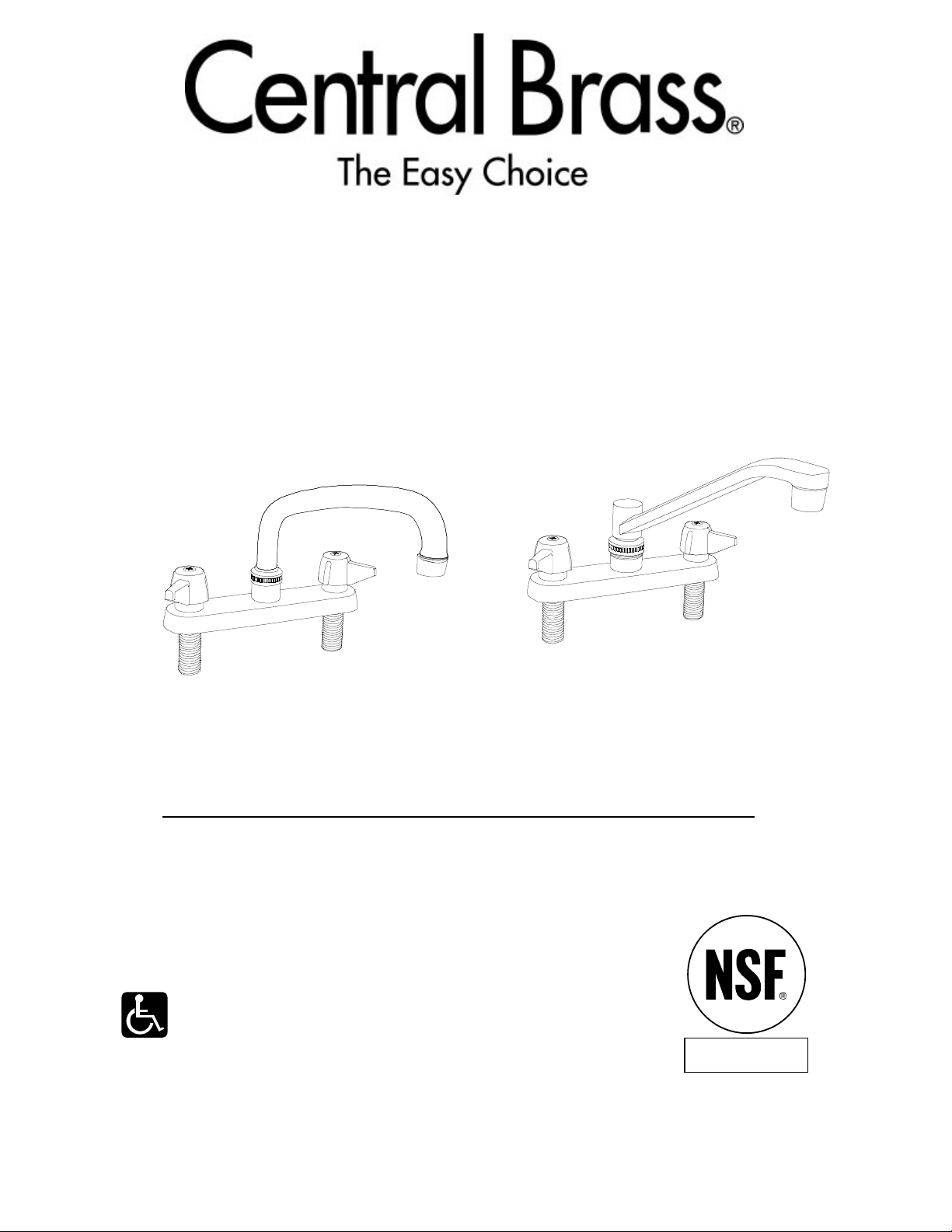
KITCHEN T OPMOUNT FAUCET
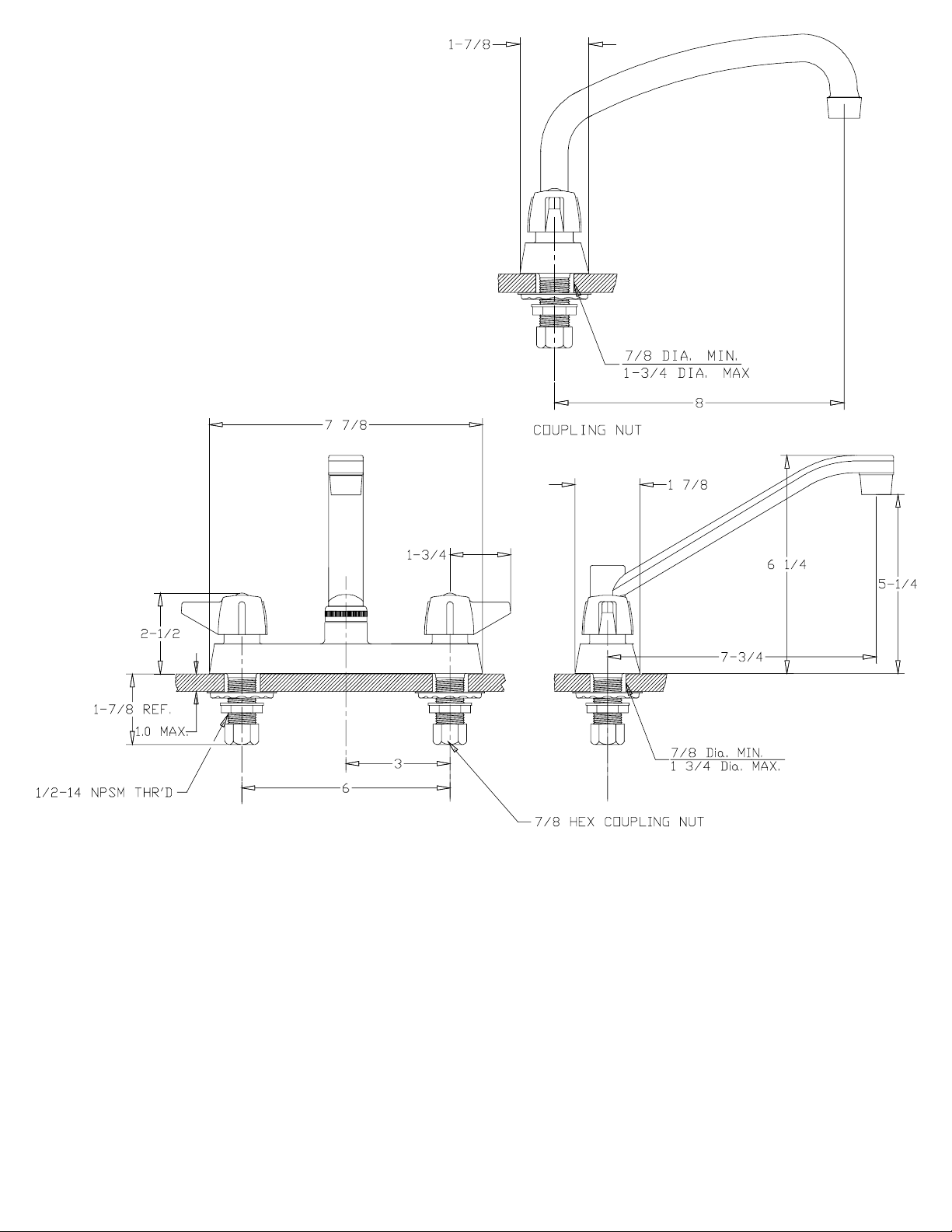
6 Inch Centers
Cast Brass Body
6" Centers with Compression Stem Assemblies
0125 - A Series with 8-inch Swivel Spout
0127 - A Series with 8-inch D-Spout
Faucets with lever, wrist or elbow
handles and compression or ceramic
stem cartridges are ADA compliant.
Certified to
ANSI/NSF 61 Section9
CENTRAL BRASS MFG CO
2950 East 55th Street, Cleveland, Ohio 44127
Phone: 216-883-0220 Fax: 216-883-0875 Email: sales @CentralBrass.com
022703 I-0125
www.CentralBrass.com
Page 2
CENTRAL BRASS
INSTALLATION INSTRUCTIONS
NOTE:
Faucets supplied without hose and
spray should be flushed with only
the aerator removed.
1. Apply a thin coat of soft plumbers putty to the bottom edge of the faucet body,
place the faucet shanks thru the holes in the sink. (Handles indexed cold on right
side, body marked on bottom front for those without handle indexes.)
2. Attach steel washer and locknuts and tighten. Connect hot water supply to left
side and cold water supply to right side. Tighten coupling nuts securely.
3. Install spout, without aerator. Turn on hot and cold water for one minute to flush
out dirt and sediment that might have accumulated during installation.
4. Install spout aerator.
5. Check all connections for leakage.
CENTRAL BRASS MFG CO
2950 East 55th Street, Cleveland, Ohio 44127
Phone: 216-883-0220 Fax: 216-883-0875 Email: sales @CentralBrass.com
022703 I-0125
www.CentralBrass.com
Page 3
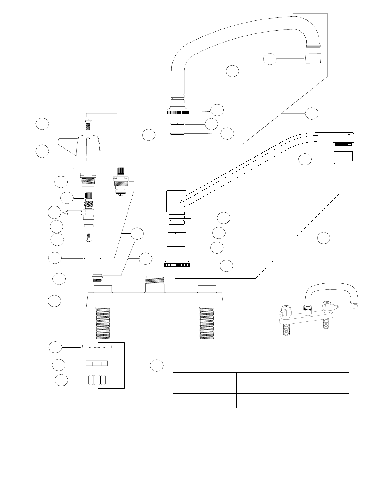
REPLACEMENT
1
*
*
*
2
3
4
PARTS
B
A
7
*
0125 Series
*
8
9
D
7
0127 Series
*
8
9
D
5
6
*
11
12
13
* These items are not offered
individually and must be
purchased as a group or unit.
Please contact Central Brass
for more information.
Phone: 216-883-0220 Fax: 216-883-0875 Email: sales @CentralBrass.com
C
10
E
Part # Description
G-1748-88W Wall Mount Spout Adapter
SU-2775-R-02 Jointed Spout (7-inch )
30-RB Swivel Rose Spray Aerator
Accessories
(includes G-1808-E & Washer X402-E)
CENTRAL BRASS MFG CO
2950 East 55th Street, Cleveland, Ohio 44127
022703 I-0125
www.CentralBrass.com
Page 4
REPLACEMENT P ARTS
# Part # Description
A G-523-C Lever Handle C Indexed with Screw (X107-F)
A G-523-H Lever Handle H Indexed with Screw (X107-F)
B G-453-EL Cold O-Ring Stem Assembly with Gasket (X1028-Y)
B G-453-ER Hot O-Ring Stem Assembly with Gasket (X1028-Y)
C K-453-C Cold O-Ring Stem Assembly with Gasket (X1028-Y) and Seat (X263-BC)
C K-453-H Hot O-Ring Stem Assembly with Gasket (X1028-Y) and Seat (X263-BC)
D SU-363-RA 8-Inch Swivel Spout with Aerator (30-M) 0125 Series
D SU-365-CA 8-Inch Swivel D-Spout with Aerator (30-M) 0127 Series
E G-913-A Coupling Nut group (1 set)
1 X10⁷- F Handle Screw (25 pcs per pack)
2 X1038-453 O-Rings (25 pcs per pack)
3 X901-WNN Stem Seat Washer (25 pcs per pack)
4 X10⁴ Seat Wa sher Screw (25 pcs per pack)
5 X1028-Y Gasket (25 pcs per pack)
6 X263-BC Replacement Seat (10 pcs per pack)
7 30-M Aerator
8 X166-FN Snap Ring (6 pcs per pack)
9 X1038-KN Spout O-Ring (25 pcs per pack)
10 X54 Crowfoot Washer (10 pcs per pack)
11 X7133-AL Locknut (10 pcs per pack)
12 X4015 Coupling Nut (4 pcs per pack)
OPTIONS & REPLACEMENT PARTS for options
Suffix
Number
2 D SU-363-JA 10-Inch Swivel Spout with Aerator (30-M)
3 D SU-363-LA 12-Inch Swivel Spout with Aerator (30-M)
4 D SU-363-MA 14-Inch Swivel Spout with Aerator (30-M)
8 D SU-357-HSA 7 ¼ Inch High-Rise Swivel Spout with Aerator (30-L)
70 A K-506-1C or 1H Acrylic Handles with C or H metal indexed buttons
Replaces
Item #
If faucet has round handles (70 or 80 suffixes) , use two Hot stem assemblies
If faucet has lever handles, use one Hot and one Cold stem assemblies
Part Number Description
X126-625B Handle Screw for Acrylic Handles suffix’s 70 or 80 (6 pcs per pack)
G-503-M-02
Metal indexed buttons C & H
for Acrylic Handles suffix’s 70 or 80 (one pair per pack)
CENTRAL BRASS MFG CO
2950 East 55th Street, Cleveland, Ohio 44127
Phone: 216-883-0220 Fax: 216-883-0875 Email: sales @CentralBrass.com
022703 I-0125
www.CentralBrass.com
Page 5
CENTRAL BRASS
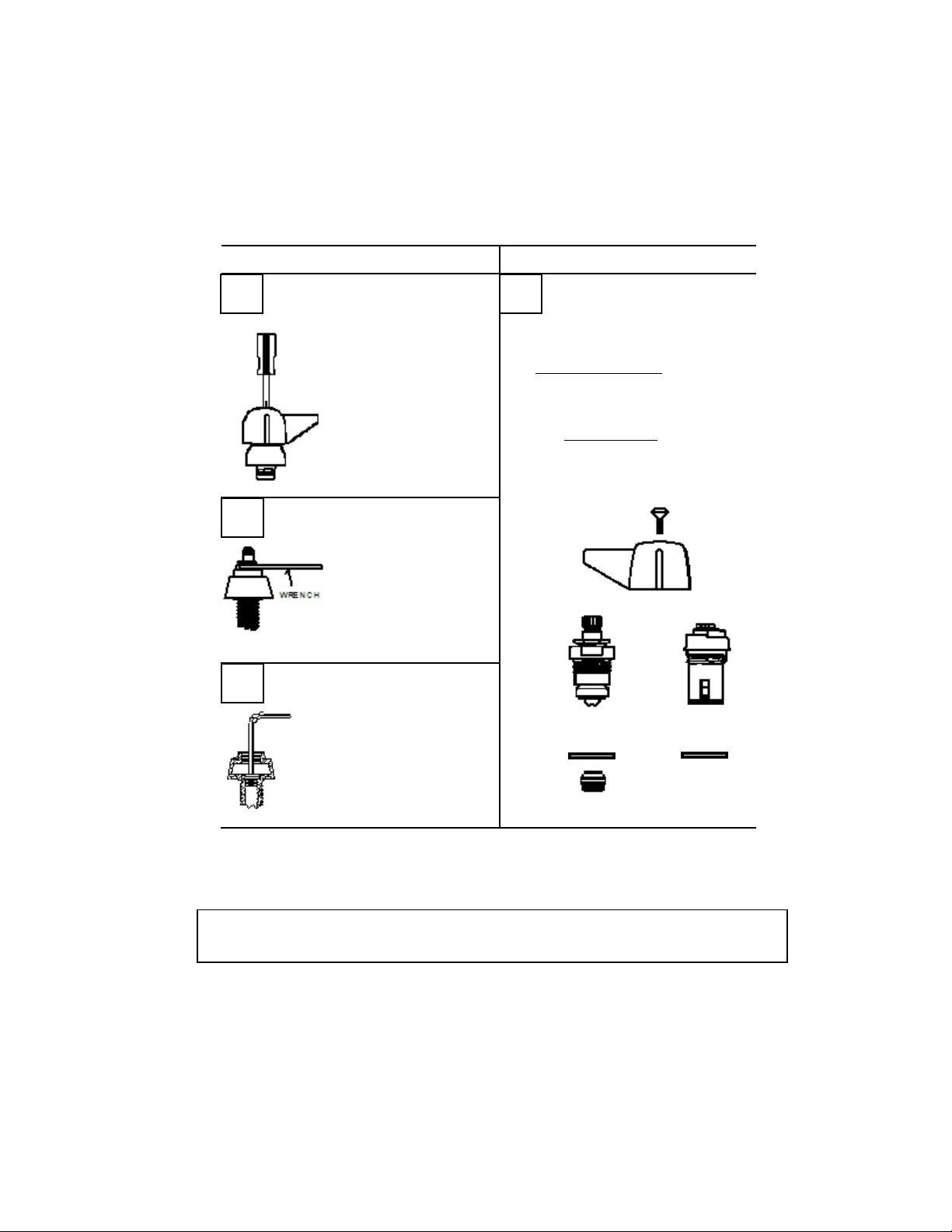
MAINTENANCE INSTRUCTIONS
1
2
3
DISASSEMBLY
REMOVE HANDLE
1. Turn of f water supply .
2. Remove screw.
3. Remove handle.
REMOVE STEM ASSEMBLY
1. Use adjustable
wrench.
2. Unscrew (counterclockwise) remove
stem unit.
REMOVE SEA T
(For compression stems only)
1. Insert 5/16" allen
wrench in seat.
2. Turn seat (counterclockwise) to remove.
REPLACEMENT
4
Use Only Genuine
Central Replacement Parts
Compression Units
G-453-ER Hot stem assembly
G-453-EL Cold stem assembly
X263-BC Replaceable Seat
Ceramic Units
K-352-H Ceramic Hot stem assembly
K-352-C Ceramic Cold stem assembly
COMPRESSION
CERAMIC
If faucet has round handles (70 or 80 suffixes) , use two Hot stem assemblies
If faucet has lever handles, use one Hot and one Cold stem assemblies
CENTRAL BRASS MFG CO
2950 East 55th Street, Cleveland, Ohio 44127
Phone: 216-883-0220 Fax: 216-883-0875 Email: sales @CentralBrass.com
022703 I-0125
www.CentralBrass.com
 Loading...