

Page 1
V4.18
Control the Elements
Owner’s Manual –
2000VSi / 2000VSx
Page 2
V4.18
[ This page intentionally left blank. ]
Page 3
V4.18
C O N G R A T U L A T I O N S !
Thank you for purchasing a new CellarPro cooling system.
Please take a minute to read through this Owner’s Manual before you unpack, install and turn on your
Cooling Unit.
If you have any questions about your new cooling unit, it is likely that you will find the answers in this
Owner’s Manual. We also have more information on our website, including the latest version of
the Owner’s Manual, www.cellarpro.com.
If you still have questions, please don’t hesitate to contact your dealer or CellarPro directly. We can
be reached during normal business hours at 1.877.726.8496. You also may contact us anytime via email at
Contact Information:
CellarPro Cooling Systems
1445 N. McDowell Blvd
Petaluma, CA 94954
877.726.8496
Email: [email protected]
Website: www.cellarpro.com
Serial Number* ________________________
*We recommend that you take a minute to fill-in your CellarPro serial number above. The serial number
has seven-digits and can be found on the printed label on the left side of your cooling unit, which may
not be accessible after you install your cooling unit. You may need this serial number in the event your
cooling unit needs service.
Don’t forget to register your cooling unit warranty at www.cellarpro.com/register
Page 4
4 V4.18
T a b l e of C o nte n t s
I. Specifications 5
II. Installation Instructions 13
III. Operating Instructions 21
IV. Troubleshooting 35
V. Limited Warranty 37
Page 5
5 V4.18
I . S p ec i fi c at io ns
Specifications
Model
Dimensions (inches) -
W x D x H
Weight
(lbs)
Power
Starting / Running
Amps
2000VSi
14.1 x 22.3 x 13.3
72
115V/60Hz
22.2 / 4.02
2000VSx
14.8 x 27.9 x 13.3
(incl. exterior hood)
81
115V/60Hz
22.2 / 4.52
Page 6
6 V4.18
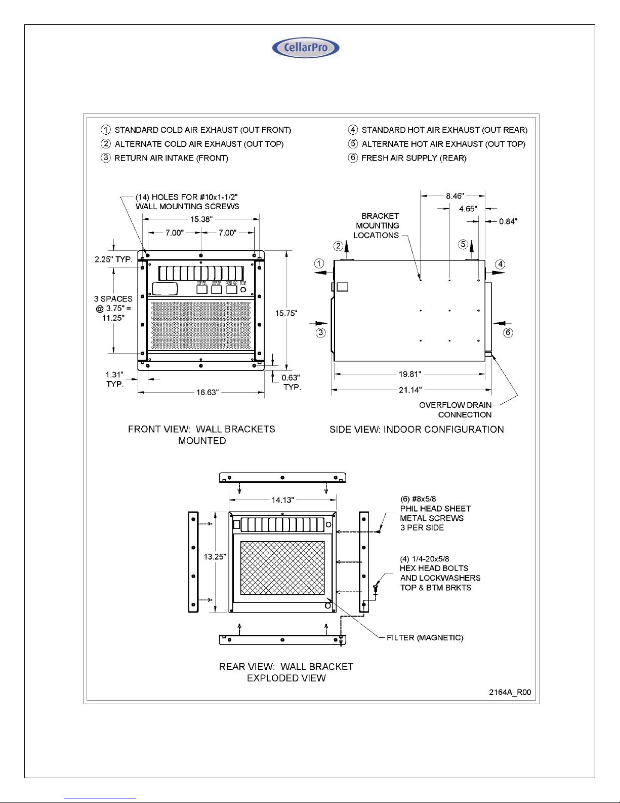
2000VSi Cut Sheet
Page 7
7 V4.18
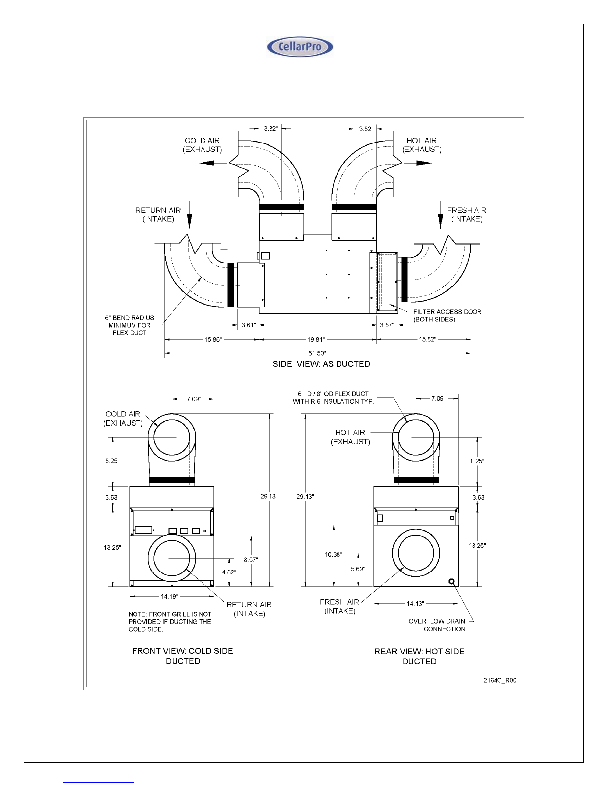
2000VSi Cut Sheet - As Ducted
Page 8
8 V4.18
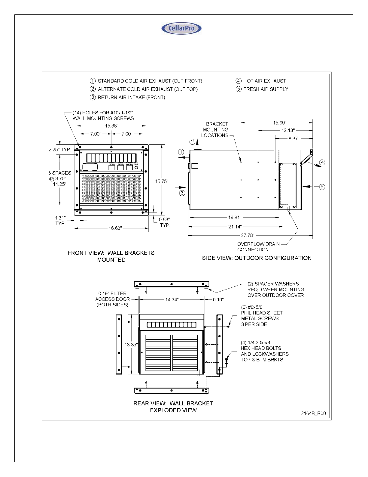
2000VSx Cut Sheet
Page 9
9 V4.18
• Placement
CellarPro 2000VS Series cooling units are designed to be installed THROUGH THE WALL, so that the rear and the
front of the cooling unit DO NOT SHARE THE SAME AIR SPACE.
When installing this unit, you must select from the pre-drilled holes to attach the mounting brackets. If you drill
new holes into the case, you will damage the internal components of the cooling unit.
The rear of the cooling unit must be installed in a space that is at least as large as the wine cellar unless the rear
intake and exhaust are ducted. Both the front and the rear of the cooling unit require a minimum clearance of 12
inches.
These units also can be placed completely INSIDE or OUTSIDE the cellar when used in combination with our duct
kits.
• Ambient Environment
2000VSi - designed for internal use only (ie sheltered from outdoor weather), the rear of the unit
can be exposed to temperature conditions ranging from 40 to 110°F.
2000VSx – designed for external use, the rear of the unit can be exposed to temperature
conditions ranging from 40 to 110°F. Refer to the Installation section for additional requirements
for outdoor exposures.
PLEASE NOTE: With our (optional) compressor heater, all of our cooling units can be used in
environments down to 20°F, and with our (optional) fan cycling switch, all of our cooling units can be
used in environments down to -20°F.
CellarPro cooling units are not designed to heat the cellar space, so if temperatures inside the cellar
drop below proper wine storage
temperatures, the cooling unit cannot
create heat inside the cellar.
• Insulation
CellarPro cooling units are designed
to be installed inside wine cellars that
have proper insulation, moisture
barriers and an airtight seal from the
environment outside the cellar.
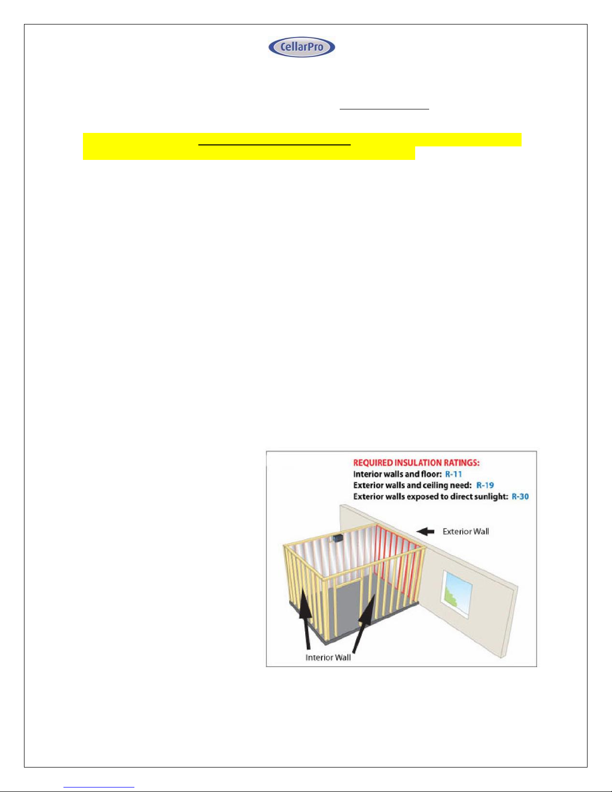
Int erior w alls and floor should
have a minimum of R-11 insulation,
and a vapor barrier on the warm side
of the insulation. The ceiling should
have a minimum of R-19 insulation
and a vapor barrier on the warm side
of the insulation. Doors also should be insulated and tightly sealed with weather s tr i pp i n g
a r ou nd t he p eri me te r of the do o r. Surface-mounted fixtures are r ecommen ded
over recessed lighting, which can allow air to leak into the cellar.
Page 10
10 V4.18
It is important that all walls, joints, doors and windows, electrical outlets and/or switches,
pipes, vents and light fixtures be sealed to prevent air and moisture from entering the cellar. If there
is a leak in the cellar, the cooling unit will build up excess condensation.
CellarPro 2000VS cooling units are equipped with a condensate management system, which
includes a stainless steel pan, a thermostatically-controlled electric heating element, and an
overflow drain at the rear of the cooling unit.
We strongly recommend that the overflow drain line (shipped loose with the cooling unit) be
connected to the overflow drain (as shown in the installation section), and that the cooling unit be
mounted level or with a slight tilt backwards (1/8” max), so that any overflow condensate is
channeled safely to the overflow drain line. In addition, we recommend turning on the electric
heating element to burn off excess condensate that accumulates in the stainless steel pan during
the initial cooling of the cellar and during high run-times, as well as in high-humidity environments.
• Fan Speeds
Your fan speed setting must be set to “High” under the following conditions:
- As the thermal load of the wine cellar increases
- As ambient temperatures increase
- Any application with ducting (front or rear)
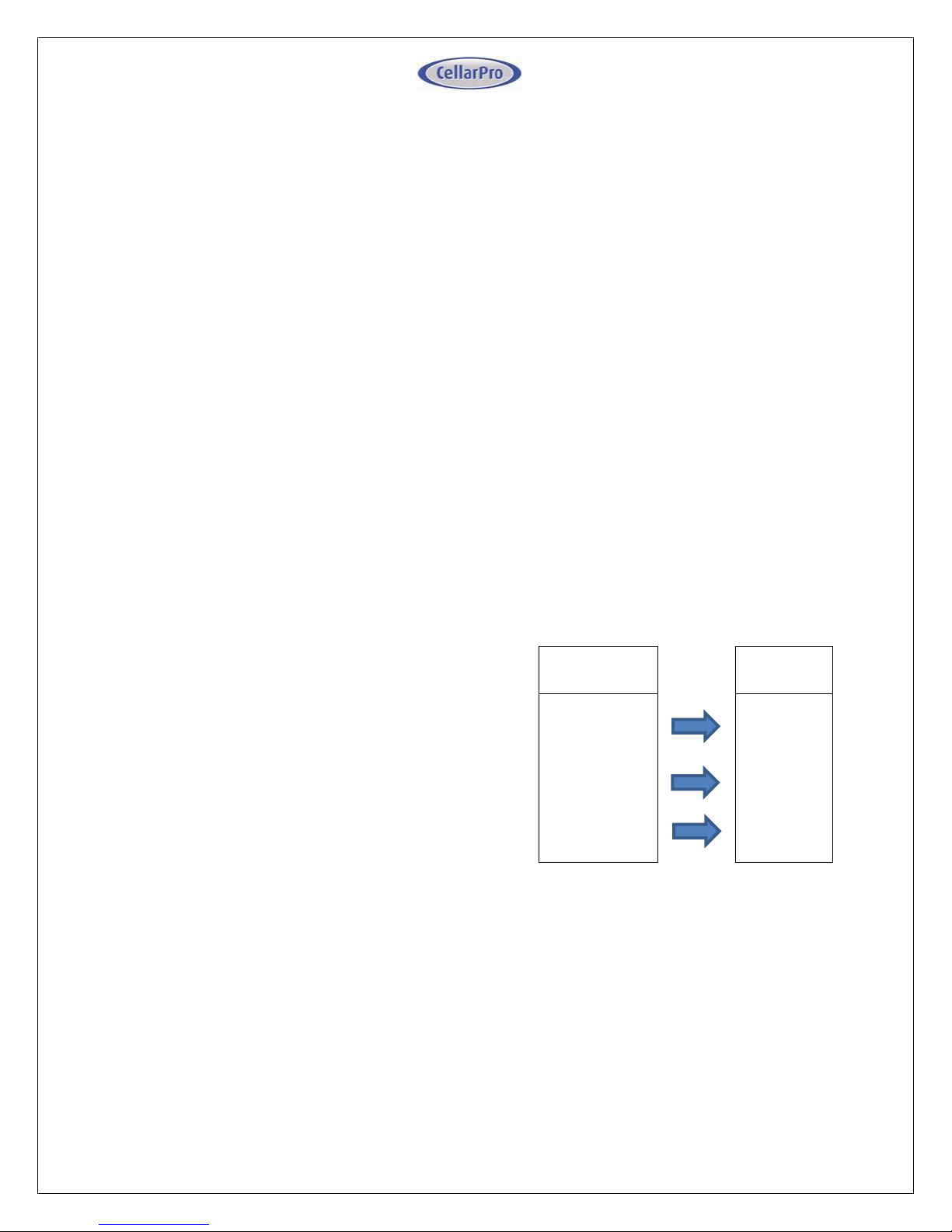
Fan Speed Guidelines
Condition
Fan Speed
Temperature of fresh air intake
<=100F
Low or
High
Temperature of fresh air intake
<=110
High
Configuration
Ducted
High
Notes:
1. The table assumes that proper space and airflow exist on the hot side of the cooling unit
2. Ducted units must always use the high fan speed.
3. We recommend using the high fan speed during the first week after installation.
Page 11
11 V4.18
• Ventilation
Adequate ventilation is critically important for the proper operation of your CellarPro cooling unit.
OUTSIDE THE CELLAR
(The Hot Side - at the rear of the cooling unit)
Condenser Air Exhaust. CellarPro 2000VS Series cooling units create significant hot air which must
be exhausted into an appropriately-sized space so that the hot air exhaust can dissipate. If
the space is constrained and/or too small, the heat will not dissipate. In this event, the cooling
unit will be forced to re-circulate its hot air exhaust and/or the static pressure will back up the
cooling unit. If this happens, the cooling unit’s ability to create cold air inside the cellar will be
compromised.
Condenser Air Intake. The condenser coils require access to cool air so that the cooling unit can
produce cold air. In addition, the cooling unit must be installed so that, after its installation, the
condenser coils are accessible for periodic cleaning or replacing of the filter.
The rear of the cooling unit must be installed in a space that is at least as large as the wine cellar unless the rear
intake and exhaust are ducted. Both the front and the rear of the cooling unit require a minimum clearance of
12 inches.
Ducting. We offer duct kits that allow the condenser air intake and/or exhaust to be ducted up
to 25 equivalent feet each with a minimum of 6” diameter ducting from start to finish, or 50
equivalent feet each with our auxiliary fan and 6” diameter ducting from start to finish. Our hotside duct kits (sold separately) attach to the rear of the cooling unit and MUST be used when
ducting our cooling units. The HIGH fan speed must always be used when ducting the cooling
unit. Using custom duct adapters instead of the CellarPro duct kits, reducing ducting below 6”
diameter, using fans at low fan speed, and/or exceeding the equivalent length limits will impair
the performance and longevity of the unit and void the manufacturer’s warranty.
INSIDE THE CELLAR
(The Cold Side - at the front of the cooling unit)
Evaporator Air Intake. CellarPro cooling units should be mounted at the highest point inside wine
cellars, so that warm air – which rises – will be the first to pass over the evaporator coils, which are
located behind the grill on the face of the cooling unit. When the warm air passes across the
evaporator coils, heat is removed the air, and the resulting cold air is exhausted into the cellar. To
ensure proper airflow, minimum clearance of 12” is required in front of the cooling unit.
Evaporator Air Exhaust. Cold air is exhausted at the top front of the cooling unit. Because CellarPro
cooling units are located at the highest point inside wine cellars, the cold air exhaust eventually
will drop to the bottom of the cellar. To ensure proper airflow and reduce temperature
Page 12
12 V4.18
stratification inside the cellar, the space in front of the cold air discharge should be clear of any
obstructions, including wine bottles, wine racks, etc.
Ducting. We offer duct kits that allow the evaporator air intake and exhaust to be ducted up to
25 equivalent feet each with a minimum of 6” diameter insulated ducting from start to finish.
Our cold-side duct kits (sold separately) attach to the front of the cooling unit and MUST be used
when ducting our cooling units. The HIGH fan speed must always be used when ducting the
cooling unit. Using custom duct adapters instead of the CellarPro duct kits, reducing ducting
below 6” diameter, using fans at low fan speed, and/or exceeding the equivalent length limits will
impair the performance and longevity of the unit and void the manufacturer’s warranty.
• Power Requirements
CellarPro cooling systems should be plugged into a dedicated non-GFI outlet connected to a 15amp circuit. The 2000VSi cooling unit uses approximately 4.89 amps during its “on” cycle, and the
2000VSx unit uses approximately 5.39 amps during its “on” cycle.
A number of variables, including the minimum set point, the temperature in the ambient
environment, the insulation of the cellar, and the thermal mass inside the cellar, will affect the
cooling unit’s runtime. It is normal for the cooling unit to run up to 75 percent of the time to
maintain proper conditions inside the cellar.
Select a power receptacle (Front or Rear) and plug the provided power cord into that receptacle.
Plug the other end of the power cord into a dedicated 15 amp circuit. A surge-protected circuit
is recommended. Set the power selector switch to energize the appropriate receptacle used
(Front or Rear).
The power cord provided for the model 2000Vsi is approved for indoor use only, while the power
cord for model 2000VSx may be used both for indoor or outdoor applications.
Page 13
13 V4.18
I I. In s t al la t i on I ns t r uc ti on s
• TEST THE UNIT BEFORE INSTALLING IT
1. Remove the unit from the box. SAVE THE BOX AND PACKING MATERIALS.
2. Plug in the power cord and let the unit run on a hard, flat surface for no more than 5
minutes.
3. Check to make sure that both fans (one in the front and one at the rear of the cooling
unit) are blowing.
4. Check that the cooling unit is discharging cold air from the front (it should be
approximately 10 - 12° F colder than the temperature on the digital display)
5. Please note: The cooling system is programmed with a 3-Minute Delay at Startup to
protect its internal components
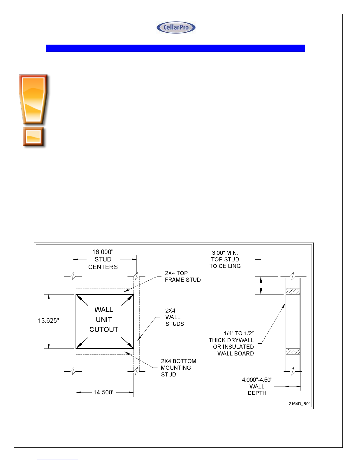
• Cut a hole in the wall that is 1/4 inch larger than the dimensions (W x H) of the cooling
unit, and create a frame to support the rear of the cooling unit. The rear of the cooling
unit should be supported by the wall through which it is installed. Horizontal 2 x 4 inch braces
should be installed between the studs below and above the cooling unit. If the studs in the wall
must be cut to accommodate the width of the cooling unit, vertical braces also should be installed
on either side of the cooling unit.
2000VS Frame and Cut-Out Diagram
Page 14
14 V4.18
• Mount the unit in the upright position close to the ceiling inside the cellar. As warm air
rises to the top of the cellar, the cooling unit pulls the warm air through the evaporator coil and
removes the heat from the warm air. Once cooled, the cold air is discharged from the front of
the cooling unit and circulates through the cellar.
• Slide the unit through from the outside of the cellar. CAUTION: Two people are
required to move the cooling unit, which is very heavy. Do not place the cooling unit
on unprotected bottle racks.
• Mount level, or tilt the cooling unit slightly backwards. The rear of the cooling unit
should be level or slightly lower (1/8” max.) than the front of the cooling unit to facilitate the
flow of excess condensate to the drain line.
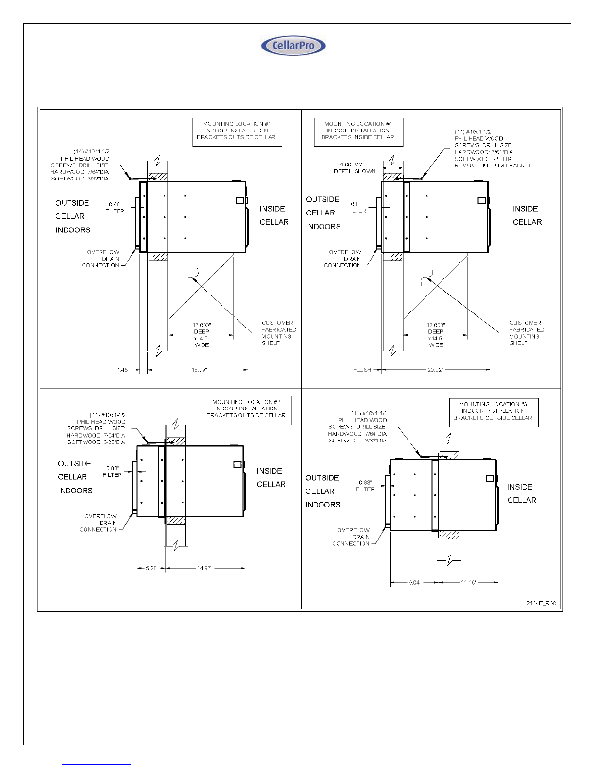
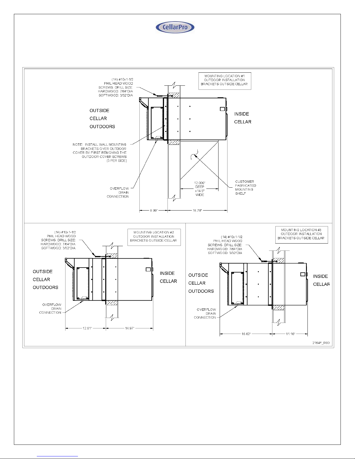
• Use our adjustable mounting brackets to support and anchor the cooling unit to the framing in
the wall. Use the (14) #10x1-1/2” flat Phillips head wood screws provided to anchor the screws
into the studs and braces. The mounting brackets can be used either inside or outside the cellar
and can be used in three different locations, as shown in the following diagrams.
Please note: when installing this unit, you must select from the pre-drilled holes to attach the mounting
brackets. If you drill new holes into the case, you will damage the internal components of the cooling unit.
Page 15
15 V4.18
2000VSi – Mounting Diagrams
Page 16
16 V4.18
2000VSx – Mounting Diagrams
Page 17
17 V4.18
• Installation Notes:
1. The unit is shipped with (4) wall mounting brackets, a 1/2" OD drain stub, a tube clamp, and a 10’
length of 1/2” I.D. condensate drain line. The required hardware is shipped loose with the unit.
a. Model 2000VSi (indoor installations): Select the desired set of mounting holes, location #1,
#2, or #3 (shown above). The mounting brackets can be used on either side of the wall.
b. Model 2000VSx (outdoor installations): The rear cover uses hole location #1. If this is also
the desired location for the mounting brackets, first make certain the rear cover is in place,
and then install the mounting brackets over the rear cover.
2. If the mounting brackets are used on the outside of the cellar in Location 1, a shelf will be needed
to support the weight of the cooling unit.
3. To attach the mounting brackets, attach the side and top brackets to the unit using (6) #8 x 5/8”
sheet metal screws. The top and bottom brackets only attach to the side brackets – there are no
mounting holes for the top and bottom mounting bracket in the case of the cooling unit. Secure
the top and bottom brackets to the side brackets with (4) 1/4”-20 x 5/8” bolts and lockwashers
(included).
4. Attach insulated foam tape to the mounting brackets on the side that will face the wall to create
an insulated and airtight seal between the wall and the brackets.
5. Once the cooling unit is installed, all cracks and gaps between the cooling unit and the cellar
should be sealed. A complete and proper seal must be made between the cellar and the cooling unit
to ensure that outside air does not enter the cellar. Use sealant tape or caulking to seal the perimeter
where the cooling unit touches the cellar. Check the seal by having a helper stand in front of the cabinet
while you shine a flashlight around the cooling unit edges to discover any gaps in sealant.
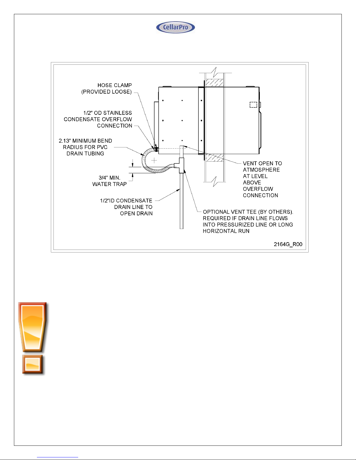
6. Slide the drain tubing over the overflow connection and secure tightly with the provided tube
clamp. Run the overflow drain tube to a gravity drain, routing so that the tube forms a water
trap near the unit. Charge the tube trap with water.
Page 18
18 V4.18
2000VS Drain Trap Detail
As shown above, the drain line should drop, then rise (but stay below the height of the fitting),
and then drop again into a drain or bucket. Then, fill the trap with water. The condensate trap
will allow any excess moisture inside the cooling unit to overcome the static pressure and flow
out of the drain line.
Please note: you must include a trap in the drain line, otherwise the condensate may not be able
to exit via the drain line and the cooling unit will drip if the drain pan overflows.
Page 19
19 V4.18
• Ducted Installations – Hot Side Ducting
1. Ductwork may be attached to the exhaust, to the fresh air return, or to both the exhaust and
return duct adapters (recommended). If ducting is attached only to one adapter, the space
must be able to provide 125CFM of exhaust or supply ventilation. If that ventilation is not
provided, it will put the performance and longevity of the unit at risk.
2. The unit is capable of operating with 50 equivalent feet of total ductwork, or 25 equivalent feet
for both the exhaust and return ducting. These specifications are based on 6” diameter flex
ducting that is fully extended to ensure a smooth inner duct wall. Elbows or bends must have
a minimum radius of 6”. All elbows, bends, grills, and adapters will add to the equivalent length,
reducing the actual length available. Use a duct sizing program to determine the total
equivalent feet of a specific duct routing design, or consult the manufacturer for
recommendations.
3. The “High” fan speed setting is required whenever the unit is ducted.
• Ducted Installations – Cold Side Ducting
1. Remove the front grill (if present) from the cooling unit before attaching the duct hoods.
2. Ductwork must be attached to BOTH the intake and exhaust openings, connecting the cooling
unit and the wine cellar.
3. The cold duct kit consists of 2 duct hoods. One hood is designed for intake and will cover the
lower portion of the cooling unit. The second hood is designed for the exhaust and will cover
the top portion of the cooling unit. Both hoods are designed to attach to the cooling unit with
3/8 screws (included). DO NOT USE SCREWS LONGER THAN 3/8”.
4. A remote sensor/bottle probe is included and is required for use with the front duct kit. The
remote sensor is designed to plug into the face of the cooling unit and terminate inside the cellar.
The remote sensor may be used to measure air or liquid temperatures inside the cellar. If
measuring air, place the sensor in the cellar in a location with good airflow. If measuring liquid,
fill a bottle with mixture of water (80-90%) and rubbing alcohol (10-20%), insert the probe into
the bottle and use the rubber stopper on the sensor to seal the bottle, and place the bottle inside
the cellar in a location with good airflow. If the bottle probe is used to measure air
temperatures, the differential (HY) on the cooling unit should be set to “4”. If the bottle probe
is used to measure liquid temperature, the differential should be set to “1”. To change the
differential, please refer to our “Advanced Operation” instructions in Section III.
5. The unit can be ducted up to 50 equivalent feet, or 25 equivalent feet for each of the supply
and return ducting. These specifications are based on 6” diameter flex ducting fully extended
to ensure a smooth inner duct wall. Elbows or bends must have a minimum radius of 6”. All
elbows, bends, grills, and adapters will add to the equivalent length, reducing the actual length
available. Use a duct sizing program to determine the total equivalent feet of a specific duct
routing design, or consult the manufacturer for recommendations.
6. The “High” fan speed setting is required for all ducted installations.
Page 20
20 V4.18
7. Condensation on the hood can occur in warm and humid environments, even though the inside
of the hood is insulated. If left unattended, this condensation may cause damage to the electrical
components inside the cooling unit. This damage is not covered by the cooling unit’s warranty.
If condensation occurs on the front duct hood, you should do the following ASAP to mitigate
the condensation:
- Insulate the duct hood by adhering insulation to the outside of the hood.
- Apply silicone caulking to the seam where the hood meets the cooling unit
•
Summary
Keep in mind the following guidelines before purchasing a wine cooling unit from CellarPro:
• If the cellar it too large for the cooling unit, the cooling unit will be unable to maintain
proper, even temperatures throughout the cellar.
• Without proper insulation and an airtight environment, the cooling unit effectively will
become a de-humidifier and potentially will produce buckets of water.
• The rear of the cooling unit must be installed in a space that is at least as large as the wine cellar unless
the rear intake and exhaust are ducted. Both the front and the rear of the cooling unit require a
minimum clearance of 12 inches.
• Without access to cool air, either because of improper ventilation or
environments that are too hot, the cooling unit will be unable to maintain proper
temperatures inside the cellar.
Under these conditions, the unit’s internal components may become damaged, the expected useful
life of the wine cooling unit may be adversely affected, and the product’s warranty may become
null and void.
Page 21
21 V4.18
I I I. Op e ra ti ng In s tr u ct i on s
• Overview
Test the cooling unit to make sure it is working properly before installing the cooling unit (refer
to the instructions at the beginning of the previous chapter.)
CellarPro cooling units are designed to maintain optimal conditions for wine storage and aging.
These conditions include steady, cool temperatures, high humidity, minimal vibration and light,
and clean air.
The settings on your CellarPro cooling unit have been preset and optimized by the factory. Before
changing any settings below, we recommend waiting 14 days to allow the cooling unit to “break in.”
The cooling unit is designed to cool the cellar gently without stripping moisture out of the cellar
environment. Therefore, it is not uncommon for the cooling unit to run nonstop for up to a week
initially, depending on the temperature inside the cellar, the size of the cellar, and the temperature
of the ambient environment. Once the cellar has reached equilibrium, it is normal for the cooling
unit to run as much as 75 percent of the time.
CellarPro cooling units are designed to maintain optimal temperatures for storing and aging fine wine.
CellarPro cooling units are not designed to maintain temperatures for serving wine, which tend to
be much colder than storage temperatures, especially serving temperatures for white and sparkling
wines.
CellarPro cooling units must be used, stored, moved and/or shipped in the upright position. Be
careful when turning the unit on its side. The unit NEVER should be turned upside down.
The cooling system is programmed with a 3-Minute Delay at Startup to protect its internal
components.
• Temperature Control
CellarPro cooling units are designed to turn “on” when the air temperature passing over the evaporator
coils inside the cellar exceeds the Minimum Set Point plus the Temperature Differential, and turn
“off” when the temperature drops below the Minimum Set Point. For example, if the Minimum
Set Point is 58°F and the Temperature Differential is 4°F, the cooling unit will turn on when
the temperature rises above 62°F inside the cellar, and it will turn off when the temperature falls
below 58°F. In this example, the average temperature inside the cellar will be 60°F.
• Basic Operation
The temperature inside the cellar can be increased or decreased by changing the Minimum Set
Point (described later in this chapter). If the cooling unit runs too much, raise the Minimum Set
Point to reduce the cycle “on” time. Most wine collectors store their wine in the range of 55 - 60°F.
CellarPro cooling units are designed to maintain appropriate levels of humidity (50 to 70
percent) inside wine cellars. In order to increase or decrease humidity inside the cellar, the
Fon
setting can be changed as described in the “Advanced Operation” section later in this chapter.
Page 22
22 V4.18
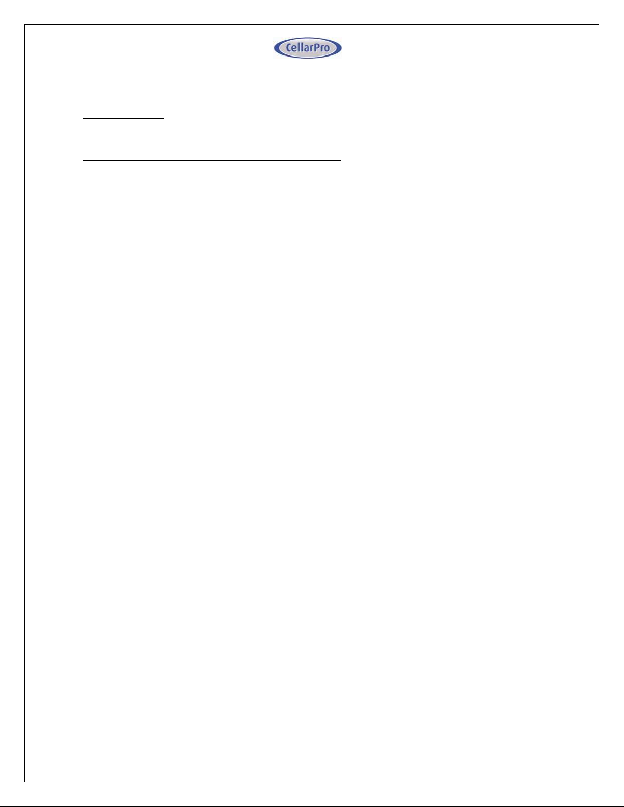
• Switch Instructions
(1) Control Panel: Maintains desired cellar environment. Factory settings are optimized for peak
performance. Controller is described in detail in the following section.
(2) Evaporator Fan Speed Selector Switch (Low - High): The evaporator fan operates on 2 speed
settings: Low, and High. For optimum sound and energy efficiency, select the lowest fan speed that
will maintain the desired cellar temperature. High speed is recommended for initial cellar pull down
and extreme temperature conditions, and is required for ducted installations.
(3) Condenser Fan Speed Selector Switch (Low - High): The condenser fan operates on 2 speed
settings: Low, and High. For optimum sound and energy efficiency, select the fan speed based on
the maximum fresh air intake temperature. Low fan speed is suitable up to 100°F fresh air intake,
and high fan speed up to 110°F. High speed is recommended for initial cellar pull down and extreme
temperature conditions, and is required for ducted installations.
(4) Power Selector Switch (Front/Rear): The unit is powered by installing the provided plug cord
in the front or rear of the unit. To use the front receptacle, set switch to “Front” and plug in the
cord at the front right side of the unit. To use the rear receptacle, set to “Rear” and plug in the cord
at the rear of the unit.
(5) Bottle Probe Jack (Bottle Probe): Plug in the remote bottle probe (sold separately) to control
the cellar by liquid temperature rather than air temperature inside the cellar. Disconnecting the
probe will automatically return the control to air temperature. When using a bottle probe, the
Temperature Differential will need to be adjusted to 1 degree as shown in the “Advanced
Operation” instructions below.
(6/7) Grounded Power Receptacle: One receptacle is located on the front right, and one on the
rear. Use the receptacle that is most convenient for the installation. Enable the receptacle by
setting the power location switch to “Front” or “Rear”.
Page 23
23 V4.18
Page 24
24 V4.18
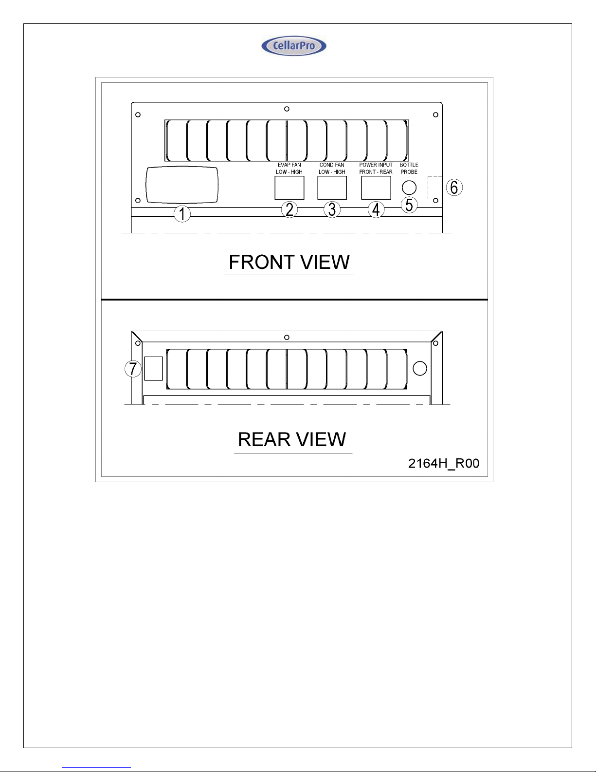
• Control Panel Instructions
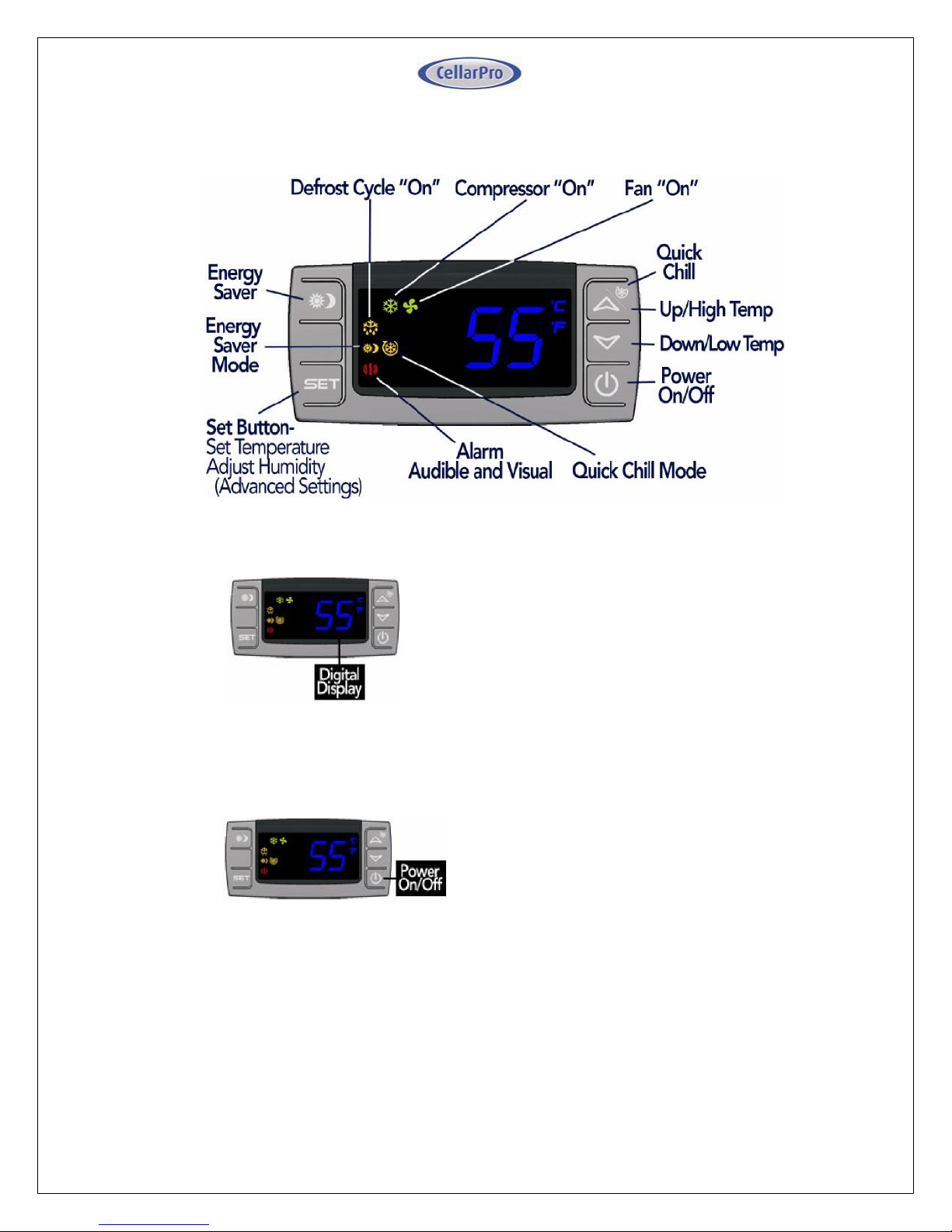
Digital Display
The temperature displayed on the control
indicates the real-time air temperature as
measured by Probe 1 (P1) located behind the
front grill of the cooling unit.
Power “On” / “Off”
Press “Power” to turn the unit on and off.
When the “Compressor On” indicator light is
on, the Compressor is running.
When the “Fan On” indicator light is on, the
Fan is running.
Please note: The cooling system is
programmed with a 3-Minute Delay at
Startup to protect internal components.
Page 25
25 V4.18
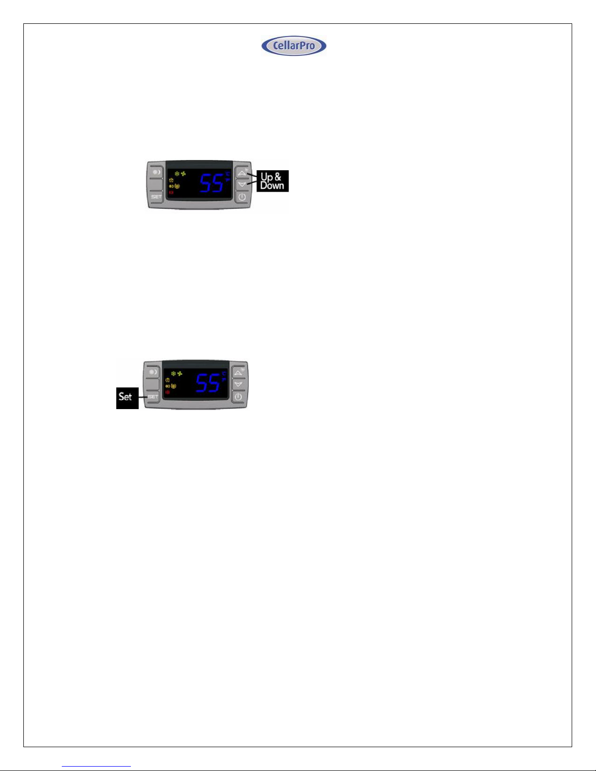
Up and Down Buttons
To view the “High Temp” recorded by the cooling
unit, press the “Up” button once.
To view the “Low Temp” recorded by the cooling
unit, press the “Down” button once.
To reset the “High Temp” or “Low Temp”, press
the “Set” button for three seconds while “Hi” or
“Lo” is displayed. “RST” will blink three times to
indicate confirmation.
Set Button
The cooling unit is factory preset with a Minimum
Set Point of 58°F and a Temperature Differential
of 4°F. This means that the cooling unit will turn
on when the display rises above 62°F (58°F + 4°F),
and turn off when the display falls below 58°F. In
this example, the average temperature inside the
cellar will be 60°F.
To view the Minimum Set Point, press the “Set”
button for one second.
To change the Minimum Set Point,
• Press the “Set” button for three seconds
until °F” blinks
• Press “Up” or “Down” button
• Press “Set” button to confirm
The “Set” temperature will blink three times to
indicate confirmation
The recommended Minimum Set Point range is 53
- 60°F. To change the Temperature Differential,
see “Advanced Operation” later in this chapter.
Page 26
26 V4.18
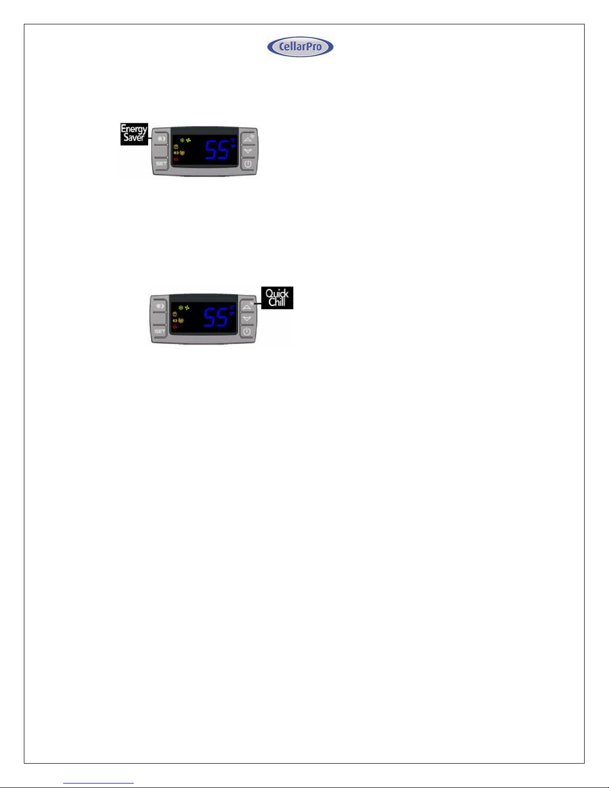
Energy Saver Button
To activate and deactivate the “Energy Saver”
mode, press the “Energy Saver” button.
The “Energy Saver” indicator light will turn on
when the cooling unit is in “Energy Saver” mode.
In “Energy Saver” mode, the Minimum Set Point
increases 4°F and the Temperature Differential is
unchanged.
Quick Chill Button
To activate the “Quick Chill” mode, press the
“Up” / “Quick Chill” button for three seconds.
To deactivate “Quick Chill”, press “Quick Chill”
button for three seconds again.
The “Quick Chill” indicator light will turn on
when the cooling unit is in “Quick Chill” mode.
In the “Quick Chill” mode, the cooling unit will
run continuously for 6 hours (or until the intake
temperature registers 50°F). This mode is useful
after loading “warm” bottles in a cellar
Page 27
27 V4.18
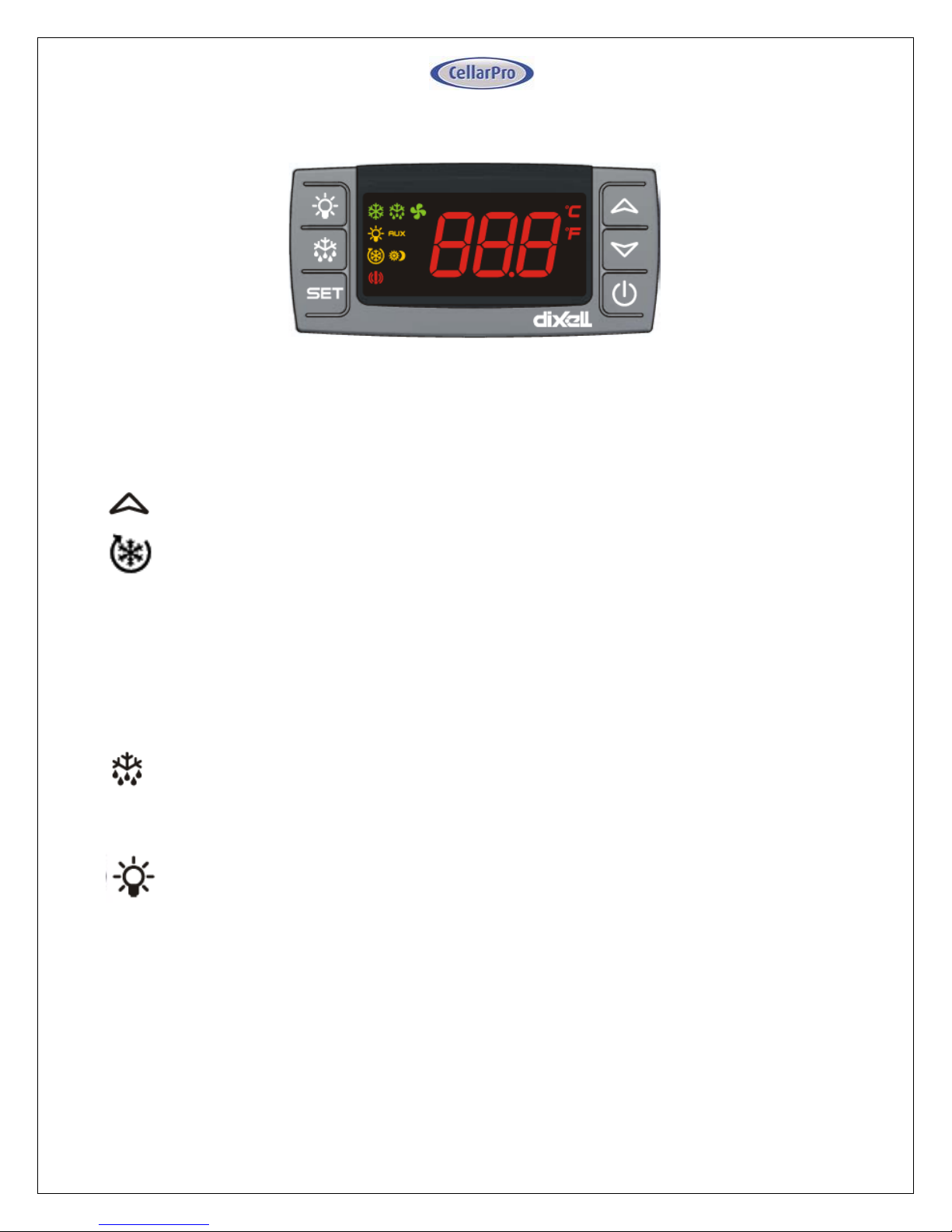
• Remote Control / Display Instructions
Digital Display
The temperature displayed on the control is red instead of blue.
Quick Chill
Button
Button
Icon
To activate the “Quick Chill” mode, press the “Up” button for three seconds
To deactivate “Quick Chill”, press the “Up” button for three seconds again
The “Quick Chill” indicator (Row 3) light will turn on when the cooling unit is in “Quick Chill”
mode,
In the “Quick Chill” mode, the cooling unit will run continuously for 6 hours (or until the
unit reaches set point.). This mode is useful after loading “warm” bottles in the cabinet.
Auto Defrost
Mode
The cooling unit has a factory default defrost cycle that initiates every 16 hours for 20
minutes. When the cooling unit is in auto-defrost mode, the “Defrost” Indicator light (Top
row) will turn on, and the evaporator fan will run.
Manual
Defrost
Hold the defrost button in for 3 seconds to initiate a manual defrost. The “Defrost”
Indicator light (Top row) will turn on for a 20 minute defrost cycle.
Light
The light button function is disabled, however pressing it will turn on/off the light indicator
on the display (2nd row).
Energy Saver
The remote display is not configured with an Energy Saver mode. The set point can be
raised manually for periods where energy savings is desired.
Page 28
28 V4.18
• CellarPro Networkable Thermostat Upgrade
Overview
Cooling units with the Networkable Thermostat (“NT”) Upgrade are configured with a
unit-mounted temperature display that provides troubleshooting, operational safety
controls and defrost cycles. The upgrade also includes 10 feet of 18/5 thermostat wire,
which must be connected to a 24VAC Networkable Thermostat.
Compatible NTs
CellarPro has tested and approved the following NT brands/models:
• Ecobee4 Pro
• Nest
• Honeywell / Lyric T6
• Any other 24VAC HVAC Thermostat with power consumption less than 4VA
Installation Instructions
IMPORTANT: CONNECT THE TERMOSTAT WIRE TO THE NT BEFORE CONNECTING POWER
TO THE COOLING UNIT.
Install the cooling unit but DO NOT connect power the cooling unit. The temperature
display on the cooling must be blank, indicating no power is connected to th e cooling
unit. It is now safe to connect the 18/5 thermostat wire to the NT.
If the NT does not have a remote sensor, the NT must be installed inside the cellar. It is
very important to locate the Thermostat in an area that gets good airflow, ideally in a
location near the air return to the cooling unit.
If the NT has a remote sensor option, it may be possible to locate the main Thermostat
outside the cellar, and the remote thermostat inside the cellar. Make sure to disable the
temperature input from the main Thermostat, and control the cellar using the remote
sensor. It is very important to locate the remote sensor in an area that gets good airflow,
ideally in a location near the air return to the cooling unit.
Connect the color-coded thermostat lead wire to the NT terminals as follows:
• Red wire to terminal “Rc” (24VAC Power Supply)
• Blue wire to terminal “C” (24VAC Common)
• Yellow wire to terminal “Y1” (cooling / compressor)
• Green wire to terminal “G” (cooling unit fan)
• The White wire in the 18/5 thermostat wire harness is not used.
Page 29
29 V4.18
If the Thermostat does not have the terminal markings listed, it will be necessary to
contact the Thermostat manufacturer to advise the correct terminal mapping.
Once the wires are connected to the NT, connect power to the cooling unit, and turn “on”
the power on the cooling unit’s digital display. The current temperature will show on
the digital display. There is a 3-minute delay before the cooling unit will start to run.
Activate the NT and begin initial set up.
Recommended Settings
The following guidelines are general recommendations to optimize the NT for wine cellar
applications. It will be necessary to reference the available NT menus and available
options from the documentation provided with the NT.
• Set the mode to “Cool Only”
• Disable all scheduling, learning, and occupancy tracking functions. These routines
are intended for comfort cooling and are not suitable for long term wine storage
applications.
• If the Thermostat has a configurable minimum/maximum set point range, set the
minimum to 47°F (or as low as possible) and set the maximum set point to 62°F.
This is the safe operating range for CellarPro cooling units.
• Enter the desired cellar set point temperature. The NT will control the cooling
unit to manage this set point temperature.
• Set fan to “Auto”.
• Compressor Minimum Off Time: If this setting is disabled by default, it must be
enabled, with a minimum off time for CellarPro products of 3 minutes.
• If the Thermostat allows high/low temperature alarms, we recommend the
following settings: 40°F (Low) and 70°F (high).
• If the Thermostat has an adjustable temperature differential (cooling on/off
range), a setting of 4°F is recommended. Many Thermostats have a tight fixed
differential of 1-2°F. In this case the cooling unit will cycle more frequently than
recommended. Therefore, it is advisable to set a longer Compressor Minimum Off
Time to minimize frequent cycling.
• If the NT has a “Change Air Filter” reminder, set the reminder for every 3 months.
This is for inspection and cleaning or replacement of the condenser filter.
• Humidity Management (with Ecobee4 Pro Thermostats:) The humidity level in the
cellar can be maximized by allowing the cooling fans to run at the end of every
cooling cycle
Page 30
30 V4.18
• From the NT, access the “Cool Dissipation Time” parameter from Main
Menu>Settings>Installation Settings Advanced Options>Thresholds and change
“Cool Dissipation Time” from Auto to a recommended value of 180 seconds (3
minutes). The time can be set from 0 to 900 seconds in 30 second increments.
• Humidity Management with Other Thermostats: our NT Update Kit is pre-
programmed with a fixed “fan off delay” of 3 minutes. Therefore, at the end of
each cooling cycle, the cooling unit fans will continue to run for 3 minutes.
Temperature Display on Cooling Unit
The temperature display provided on the cooling unit enhances the functionality of the
NT for wine cellar applications. Alarms trigger an audible alarm only at the cooling unit,
the alarms are not communicated through the NT. Consult the cooling unit Owner’s
Manual for detailed troubleshooting information related to these alarms.
• The “Set” button has no effect since the set point is managed by the NT.
• The following parameters and functions are not available with the NT
configuration: HY, FON, SET, HES, Quick Chill and Energy Saver.
• For self-contained cooling units, high and low ambient temperature alarms
(“HA2”/”LA2”) will behave as follows (refer to the cooling unit’s Owner’s Manual
for addition information):
o “HA2” alarm - the compressor will shut down until it cools off.
o “LA2” alarm - will not shut down the unit and contact CellarPro asa p.
• A start up safety delay of 3 minutes is enabled when power is first supplied to the
unit, or when recovering from a power failure.
• The defrost cycle will be managed automatically based on the unit configuration.
When the cooling unit is in defrost, “DEF” is shown on the display.
• The power button can be used to turn off the compressor. When the display reads
“OFF”, the compressor is turned off, however the cooling unit fans may turn
on/off based on the call for fans from the NT.
• To completely shut down the system, turn off both the cooling unit and the NT,
or disconnect power to the cooling unit.
Page 31
31 V4.18
Advanced Operation
CellarPro cooling systems can be programmed with advanced settings to achieve more
control over conditions inside the cellar. Conditions like humidity, the Tempe rature
Differential, and alarm settings all can be modifie d for custom applications. To access
the advanced settings, do the following:
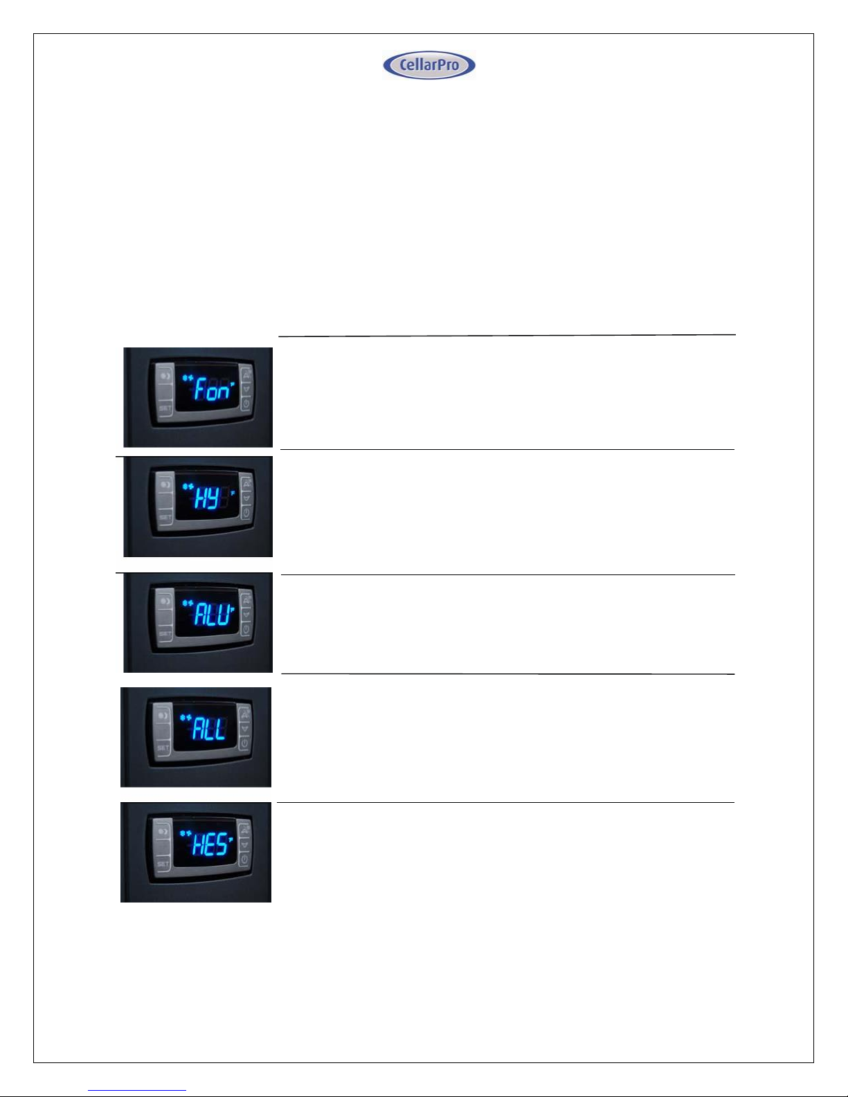
Press the “Set” button and the “Down” button together at the same time, and hold for
three seconds. Then, use the “Up” or “Down” button to scroll to the following screen:
LOW TEMPERATURE ALARM: The factory preset for this setting is
45”.
This setting designates the Low temperature inside the cellar at
which the alarm is triggered. We recommend leaving this setting
at the factory preset.
ENERGY SAVINGS MODE DIFFERENTIAL: The factory preset for this
setting is “4”.
Thi s se tt ing in creases or decreas es the Tempera ture
D if f er e nt i al f o r t he E ne r gy S av in gs M o de . T h e
recommended setting is 4.
HUMIDITY: The factory preset for this setting is “3”.
If the humidity inside the cellar is too low, press the “Set”
button, then use the “Up” button until the desired setting is
reached. The recommended range for this setting is 3-6.
TEMPERATURE DIFFERENTIAL: The factory preset for this setting is 4”.
This setting determines the Temperature Differential and
therefore the temperature at which the cooling unit will cycle on.
The recommended setting is 4 if you are measuring air
temperature, or 1 if you are measuring liquid temperature with
our remote thermostat bottle probe.
HIGH TEMP ALARM: The factory preset for this setting is “70”.
This setting designates the High temperature inside the
cellar at which the alarm is triggered. We recommend
leaving this setting at the factory preset.
Page 32
32 V4.18
Standard Protection Mechanisms
The cooling unit is programmed to shut down certain components to protect those components, as
well as the wine inside the cellar, under the following circumstances:
Scenario
What it means
What happens
P1 Alarm
Probe 1, which senses the
temperature inside the cellar and
controls the on/off cycles of the
cooling unit, has failed
The cooling unit enters a timed
auto-cycle mode until Probe 1 is
repaired or replaced. In this mode,
the cooling unit will turn on for 12
minutes and off for 8 minutes.
Scenario
What it means
What happens
HA2 Alarm
P3 > 130° F
The condenser probe is measuring
temperatures that are too hot.
The compressor will turn off until
the condenser temperature falls
below 85°F
See the section below titled
“Alarms” for instructions how to
resolve “HA2” alarms.
Page 33
33 V4.18
Maintenance
The condenser coils at the back of the cooling unit will collect dust, dirt and lint over time.
Therefore, it is critically important to keep the coils clean, and/or replace the poly-coated filter,
and/or clean the cleanable filter screen periodically. If the condenser coils or filter become
clogged, the cooling unit will not have proper airflow and its performance and longevity will be
compromised.
Only use CellarPro filters. Using a pleated or other type filter will cause serious damage to the condenser
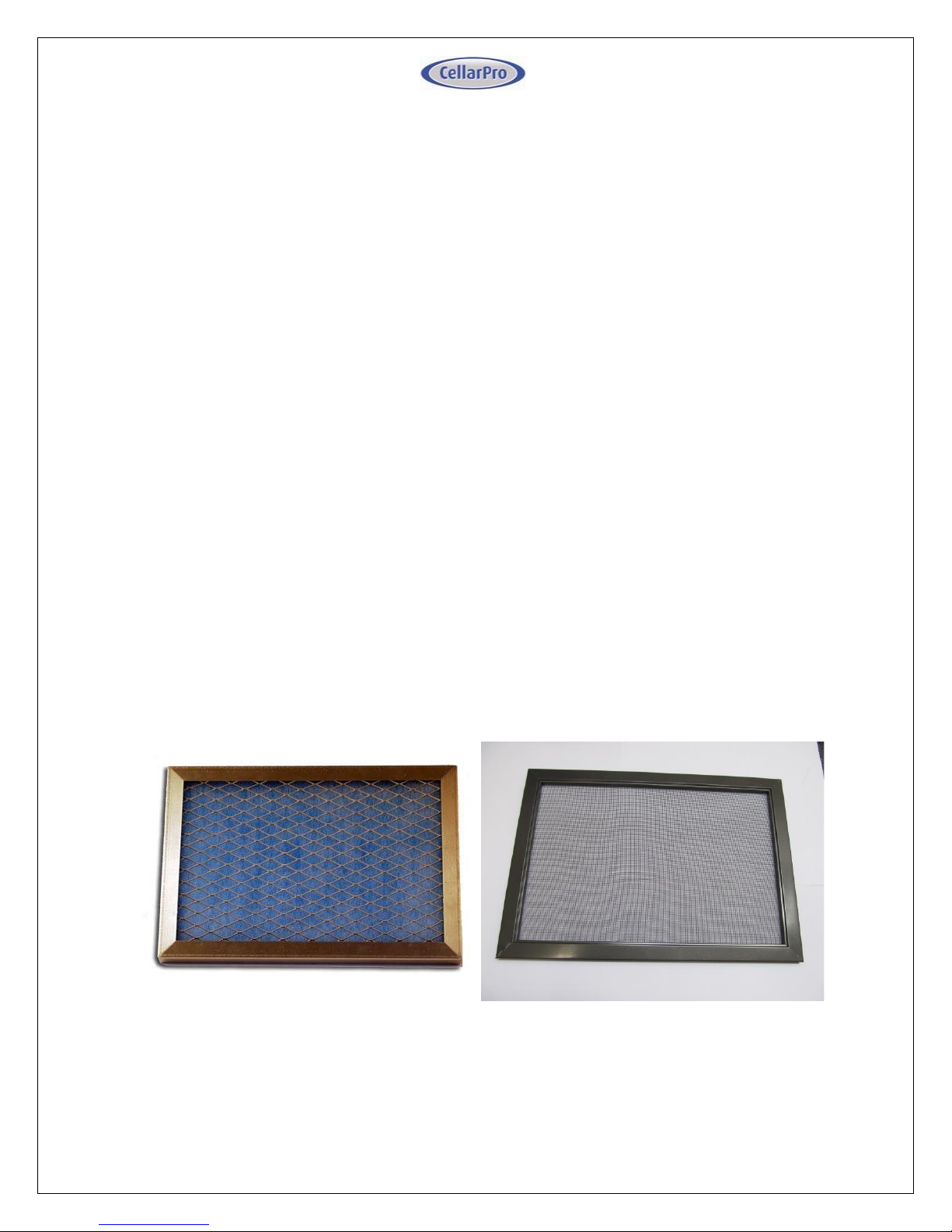
fan and the compressor. The filter frames are magnetic and attach to the rear of the cooling unit.
- To replace the poly-coated filter, remove the filter frame from the cooling unit, pull out
the old filter media, and insert a new filter. Reattach the filter with the blue side facing
out, making sure the magnet strips make firm contact with the unit housing.
- To clean the cleanable filter screen, remove the filter screen and rinse the screen with
water and mild soap until all debris is removed. Shake off the excess water, then reattach
the filter to the cooling unit, making sure the magnet strips make firm contact with the
unit housing.
- The condenser coils themselves also can be cleaned with a vacuum cleaner – ideally with
a brush attachment to loosen dust caught between the fins.
2000VSi Replaceable (Poly-coated)
Filter
2000VSx Cleanble Filter Screen
Page 34
34 V4.18
Alarms
The cooling unit has both an audible notification and a visual alarm indicator (shown in “red” on the control
panel) that are activated when an alarm is triggered.
Please note
: the temperature alarm (HA) is disabled
during the first 23 hours of operation after the cooling unit is plugged in and/or turned on.
Alarm Code
What it means
What to do
P1, P3
Probe Failure
Call CellarPro at 877.726.8496
HA The temperature inside
the cellar is too warm
(above 70°F for more
than 1 hour)
Check if the cellar has a leak
Check if door was left open
Lower the ambient temperatures
HA2
The condenser temperature
is too high (above 130°)
1. Turn the fan switch to the “High” fan speed.
2. There are 2 independent fans in the cooling unit.
Make sure that the condenser fan (at the rear of the
cooling unit) is operating.
3. Make sure that the filter (if used) or the coils are
clean.
4. Check for any blockages of the hot air intake or
exhaust.
5. If the cooling unit is a VSx (ie external) unit, the hood
should be shaded.
If your unit continues to have issues, turn off the cooling
unit and call CellarPro at 877.726.8496 or email
LA
The temperature inside the
cellar is too cold (below 45°F)
Raise the ambient temperature
Raise the “Minimum Set Point”
LA2
The temperature at the
condenser coils (outside
the cabinet) has dropped
below the alarm
temperature setting
Turn off your cooling unit immediately and call CellarPro
at 877.726.8496 or email [email protected]
Page 35
35 V4.18
IV. Trou ble s h o o t i n g
Cooling Unit Runs Constantly
Improper installation, inadequate insulation, or a cellar that is too large will cause the cooling
unit to run continuously and cannot be troubleshooted.
The cooling unit is designed to turn on when the air temperature in the cellar rises ABOVE the
Minimum Set Point + Temperature Differential, and turn off when the air temperature falls below
the Minimum Set Point. For example, if the Minimum Set Point is 58°F and the Temperature
Differential is 4°F, the cooling unit will turn on above 62°F and turn off below 58° F. In this example,
the average temperature inside the cellar will be 60°F.
When bottles are first loaded in the cellar, the cooling unit will run continuously (even up to a week)
until the temperature inside the cellar falls below the Set Point.
CellarPro 3200 and 4200 Series cooling units are designed to maintain proper wine storage
temperatures inside cellars with adequate insulation up to 1500 cubic feet, depending on the cooling
unit, thermal load and desired cellar temperature.
Hot weather conditions, insufficient ventilation and/or dirty condenser filters may cause the
cooling unit to run continuously. To reduce cycle times,
1. Remove any obstructions to air flow to or from the unit
2. Check to make sure the condenser filter is clean
3. Increase the Fan speed to High
4. Increase the supply of cool air to the space outside the condenser coils, using a fan, ducting
or an exhaust system to remove heat from the space.
5. Raise the Minimum Set Point on the cooling unit
Cooling Unit Is Dripping
The cooling unit is designed to remove excess moisture from inside the cellar, which collects in the
drip pan of the cooling unit and is evaporated by the condensate heater. Excess moisture can occur
when the cooling unit runs constantly, when the Minimum Set Point is too low and/or when the cellar
doesn’t have a good seal from the outside environment. To eliminate overflow, do the following:
1. Ensure the condensate overflow drain line is not blocked, that the drain line is trapped
and the trap is filled with water.
2. Make sure the unit is slightly tilted, with the front slightly higher than the rear.
3. Check to make sure the cellar has airtight seals, including the door(s), light fixtures, and all
walls, ceiling and floor.
4. Turn the fan to the “High” setting.
Page 36
36 V4.18
HA2 Alarm Has Been Triggered
The cooling unit is designed to measure the temperature of the condenser coils and, if the
temperature exceeds 130°F, the HA2 alarm will display on the control panel.
If this alarm happens
when you first receive and start operating your CellarPro cooling unit
,
turn the fan to the “High” setting, check for appropriate installation and ventilation on the Hot
Side of the cooling unit (Chapter II). Also, make sure that there aren’t any obstructions to the
intake and/or exhaust vents.
If the cooling unit has been operating for several months without any problems and the alarm
occurs:
1. Turn the fan switch to the “High” fan speed.
2. There are 2 independent fans in the cooling unit. Make sure that the condenser fan (at
the rear of the cooling unit) is operating.
3. Make sure that the filter (if used) or the coils are clean.
4. Check for any blockages of the hot air intake or exhaust.
5. If the cooling unit is a VSx (ie external) unit, the hood should be shaded.
If your unit continues to have issues, turn off the cooling unit and call CellarPro at 877.726.8496 or
email [email protected].
LA2 Alarm has been triggered
As noted above, the cooling unit is designed to measure the temperature of the condenser coils
and, if the temperature drops below a certain point, the LA2 alarm will display on the control
panel. Please call CellarPro at 877.726.8496 if this alarm occurs.
Cooling Unit Won’t Turn On
The cooling system is programmed with a
3-Minute Delay at Startup
to protect its internal
components.
Page 37
37 V4.18
V I . L im it ed Wa r ra n ty
For five years from the date of original delivery, your CellarPro warranty covers the internal
compressor if it proves to be defective in materials or workmanship. In addition, for two years
from the date of original delivery, your CellarPro warranty covers all parts and labor to repair or
replace any components in the wine cooling unit that prove to be defective in materials or
workmanship.
Under the terms of this warranty, CellarPro will repair or replace the original cooling unit with a
new or refurbished cooling unit and, once replaced, the original cooling unit must be
returned to CellarPro.
All service provided by CellarPro under the above warranty must be performed by a designated repair
center, unless otherwise specified by CellarPro. Purchaser is responsible for shipping the cooling
unit to and from CellarPro or to and from a designated repair facility, and for removing and
reinstalling the cooling unit from the wine cellar.
The limited warranty applies only to cooling units purchased from the factory or an authorized dealer.
Damage caused by others or by any cause beyond the control of CellarPro, shall not be considered
defects in material or workmanship and are not covered by the warranty. The limited warranty does
not cover any parts or labor to correct any defect caused by negligence, commercial use, accident, or
improper use, maintenance, installation, service or repair.
THE REMEDIES DESCRIBED ABOVE FOR EACH WARRANTY ARE THE ONLY ONES, WHICH
CELLARPRO WILL PROVIDE, EITHER UNDER THESE WARRANTIES OR UNDER ANY WARRANTY
ARISING BY OPERATION OF LAW. CELLARPRO WILL NOT BE RESPONSIBLE FOR ANY
CONSEQUENTIAL OR INCIDENTAL DAMAGES ARISING FROM THE BREACH OF THESE WARRANTIES
OR ANY OTHER WARRANTIES, WHETHER EXPRESS, IMPLIED OR STATUTORY.
Some states do not allow the exclusion or limitation of incidental or consequential damages, so the
above limitation or exclusion may not apply to you. This warranty gives you specific legal rights
and you may also have other legal rights, which vary from state to state.
To receive parts and/or service and the name of a CellarPro designated repair facility nearest you, contact
your CellarPro dealer. You may also contact CellarPro directly by calling us at 877.726.8496.
 Loading...