

Page 1
MICROMETER ADJUSTABLE
“CLICK TYPE”
TORQUE WRENCH
REPAIR,
MAINTENANCE
AND
TROUBLESHOOTING
MANUAL
SUGGESTED PRICE $35.00
PART NUMBER: 21-201-01
ISSUED NOVEMBER , 2001
Page 2

TABLE OF CONTENTS
TITLE PAGE(S)
SAFETY INSTRUCTIONS – WARNING & CAUTION
1
CDI TORQUE TESTING EQUIPMENT - Illustration
2
INTRODUCTION 3
CLEANING 3
LUBRICATION 3
REPAIR TOOLS REQUIRED 3
OTHER REQUIRED MATERIALS 4
INSPECTION 4
CAUTION – Customer misuse
4
ACCURACY VERIFICATION AND MINOR CALIBRATION
PROCEDURE
4/8
MINOR CALIBRATION ADJUSTMENT 6/8
Handle Locking -Table 8
CALIBRATION ACCURACY CHECK - Illustration 8
MAJOR CALIBRATION AND REPAIR 8/14
To disassemble the tube 9
To recalibrate the wrench 9/14
Pawl Orientation Chart 10
Pawl Size - Table 11
Pawl Style Chart - Table 11
i
Page 3

TITLE PAGE(S)
Pawl Identification Code Example 11
Pawl Selection Chart - Table 12
Example #1 with Pawl Selection Chart - Table 13
Example #2 with Pawl Selection Chart - Table 14
To Disassemble and Check Parts 15/17
CAUTION – Positive Spring Pressure 17
To check for positive pressure on the spring 17
HANDLE/LOCK RING REPAIR 18/23
To disassemble the handle/lock ring 18/21
To assemble the handle/ lock ring 21/23
Handle Locking - Table 23
Calibration Instructions for Pre-Set Torque Wrenches 23/24
CDI Pre-Set Torque Wrench Ranges & Adjustment Tool Part Numbers 24
Troubleshooting 24
Micrometer Adjustable Torque Wrench Troubleshooting Matrix 25/26
ii
Page 4

REVISIONS –
The CDI Micrometer Adjustable Torque Wrench Repair Manual was originated and first
issued in November 2001. The manual will be reviewed and revised as necessary to
assure that it contains the latest changes in product or repair changes. In between
revision, product bulletins may be issued to assure any changes in product or repairs are
supplied to authorized repair facilities.
REV.
Date Issued
Affected Pages
Approved
November 2001
Written By: Donna E. Brunot
Photographs By: Gary Fitzhugh
iii
Page 5

CDI MICROMETER ADJUSTABLE AND PRE-SET TORQUE WRENCH
REPAIR, MAINTENANCE AND TROUBLESHOOTING INSTRUCTIONS
SAFETY INSTRUCTIONS
Failure to follow WARNING instructions can cause personal injury to the operator.
Failure to follow CAUTION instructions can cause the equipment to fail or break in use.
! WARNING
Always wear Safety Glasses or goggles when using or repairing hand tools.
Read this manual completely before repairing torque wrenches.
DO NOT use or test a wrench that shows signs of damage (bent tubes, cracked or
broken parts) caused by misuse. Recommend replacement.
DO NOT use cheater extensions on the handles or tube to apply torque.
DO NOT exceed rated maximum torque.
Check all sockets or other test accessories for wear, damage or crack prior to their
use with torque wrenches. Do not exceed their rated maximum torque.
Always pull (DO NOT push) to apply torque. Adjust your stance to prevent a fall if
something should give suddenly.
Ratchet head torque wrenches must be checked for full (positive) engagement of the
ratchet in the direction of use prior to applying a load on the wrench. Broken or
slipping ratchets can cause injury.
CAUTION
Periodic recalibration is necessary to maintain accuracy.
Periodic examination and cleaning is necessary to maintain the wrench
Page 1
Page 6
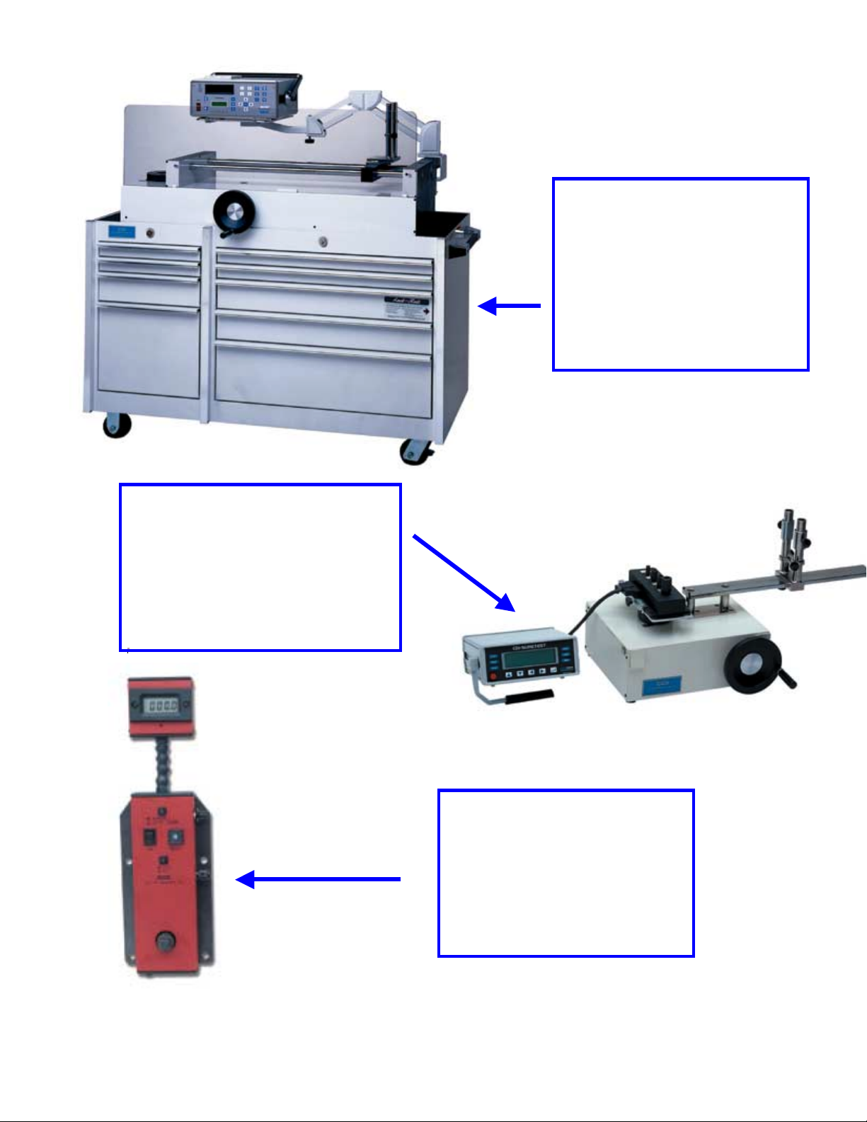
SURETEST
TORQUE
CALIBRATION
SYSTEM
MULTITEST
TORQUE
CALIBRATION
SYSTEM
ETT
ELECTRONIC
TORQUE
TESTER
Page 2
Page 7

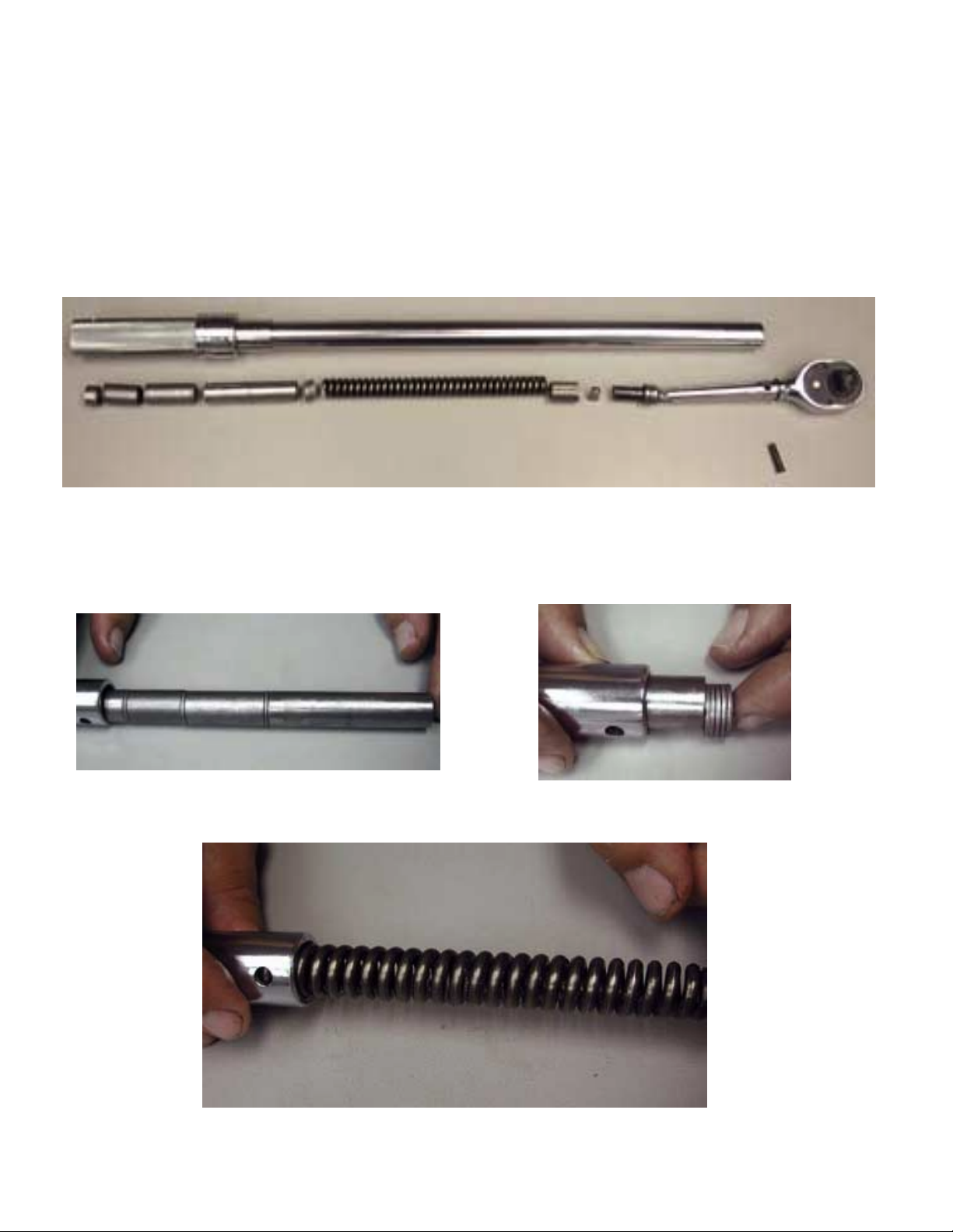
INTRODUCTION
This manual covers the calibration, repair, maintenance and a troubleshooting guide to
identify and remedy problems that could occur with the CDI Torque Wrenches. Each
wrench model has an Exploded Illustration that lists the component parts and shows
assembly particulars. The exploded illustration must be used as a guide for assembling
CDI Torque Wrenches. CDI has a Service Center that performs repairs and calibration on
all of our products at the factory, plus a list of factory authorized repair/calibration
centers throughout the world. Contact CDI Service Center at (626) 965-0668 or
sales@cditorque.com for technical assistance on the repair or calibration of CDI Torque
Products.
CLEANING
Wipe all exterior parts with a dry, clean and lint free cloth. DO NOT USE any abrasive
or corrosive materials to clean any components of the CDI Torque Wrenches. After
assembly, a non-abrasive polishing agent applied with a dry, clean and lint free cloth may
be used to polish the chrome exterior parts.
LUBRICATION
Super Lube MULTI-Purpose Synthetic Lubrication with Teflon, CDI Part #10-
1000. NO SUBSTITUTES ALLOWED.
REPAIR TOOLS REQUIRED
Micrometer Adjustable Torque Wrenches
*
1
1
2
1
Torque Tester (range determined by the torque wrench to be tested)
Flat blade mini screwdriver (max. blade size .063 or 1.6mm)
End Cutter (modified jaws ground flat on top to allow rivet removal)
CDI Calibration Crank Handle (Pt. # 600-8-1 & 600-8-2) 7/16” & 3/8” hex
0 to 1” micrometer with tenth (.0000) increments
1 16 oz. hammer
1 40 to 200 In. Lb. CDI Torque Wrench
1 3/8” 6 Point Deep Socket
1 7/16” 6 Point Deep Socket
*We recommend that CDI torque testers are used to test the calibration accuracy of
CDI manufactured torque products.
CDI manufactures a complete line of torque testing equipment from moderately
priced testers to complete state of the art test systems used in metrology calibration
laboratories all over the world. Contact CDI Sales Department at (626) 965-0668 or
sales@cditorque.com
for the nearest distributor of CDI Torque Products.
Page 3
Page 8

OTHER REQUIRED MATERIALS
Torque Seal (Part # 10-1100)
INSPECTION
Inspect all wrenches repaired to determine that they are in an operational condition by
visually inspecting for worn, broken, cracked or damaged parts. Replace parts not found
to be in satisfactory condition.
CAUTION
Some torque wrenches are abused or damage beyond repair. The most common abuse is
using the wrench as a breaker bar to loosen a bolt or nut. This type of misuse is evident if
the tube or the drive is bent in the counterclockwise direction in relation to the tube or
marks from a cheater bar are on the tube or handle. DO NOT REPAIR the wrench if it
shows signs of this type of misuse. The component parts may be permanently damaged.
The SAFETY and INTEGRITY of the wrench could be impaired. Recommend that the
wrench be replaced.
ACCURACY VERIFICATION AND MINOR CALIBRATION PROCEDURE
This procedure is to be used to check the accuracy and, if necessary, perform a minor
adjustment on calibration. It must also be used after a major calibration.
There are two major international standards that establish torque wrench accuracy
requirements. They are ASME B107.14 M Hand Torque Tools (American Society of
Mechanical Engineers) and ISO 6789 Hand Torque Tools – Requirements and Test
Methods (International Organization for Standardization). Both standards are recognized
as established accuracy test methods and referenced in this section. ASME and ISO
standards are subject to review and changes. The repair manual will be reviewed and
revised periodically but may not reflect the latest revisions of the specifications listed
above.
ASME B107.14M
1. Preload the wrench by setting the wrench at 50% of full scale and operating three
times in the direction of the test.
2. Reset handle to 20% of full scale. Place square drive in tester. Adjust the loading
point of the tester until the load is being applied in the center of the handle.
Page 4
Page 9
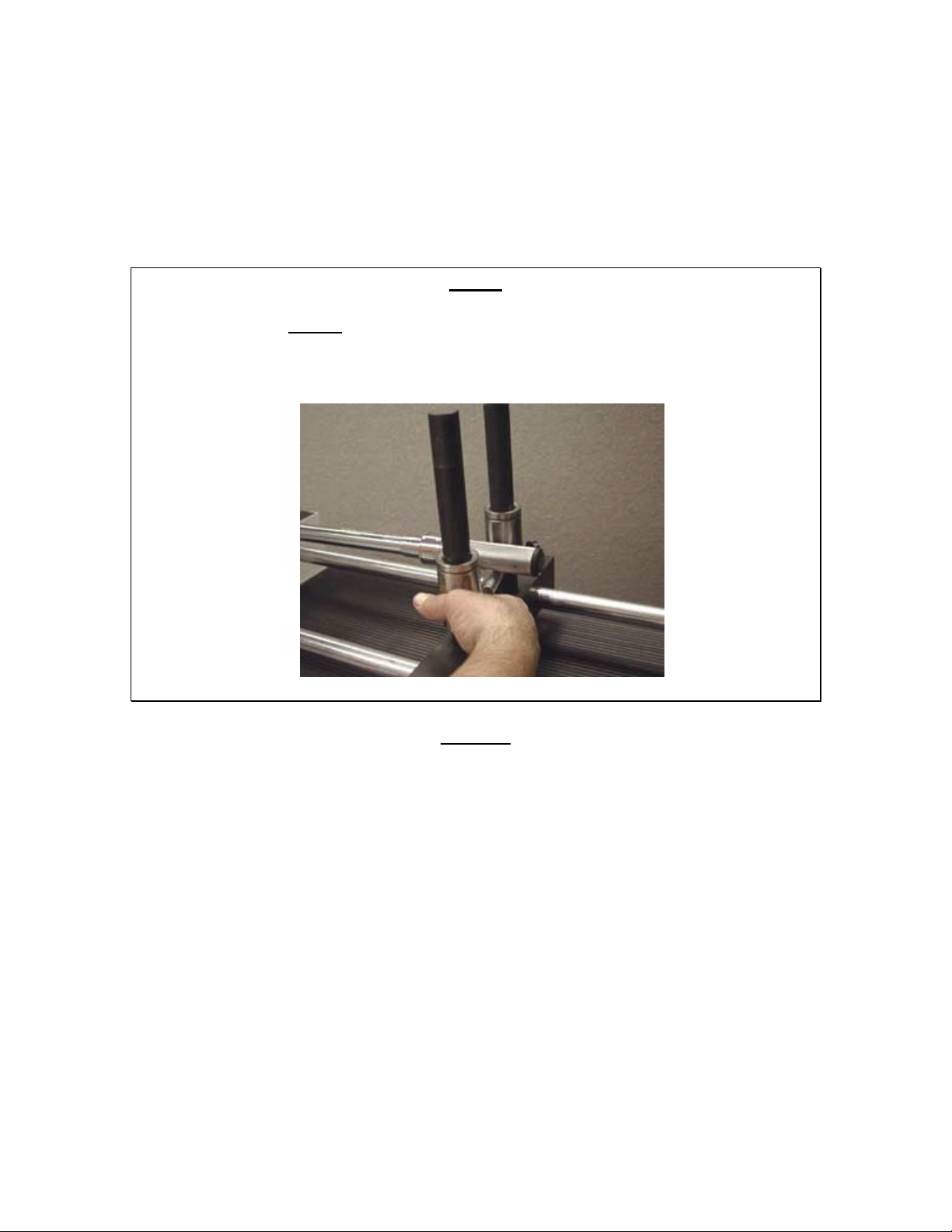
3. Test the wrench three (3) times at 20% noting the accuracy error for each reading. Set
and test the wrench three (3) times at 60% and 100% of full scale noting the accuracy
error for each reading. If the readings are within the accuracy requirements for the
direction no calibration adjustment is required.
4. Test the torque wrench in the opposite direction, if required, by following steps 1
through 4 in that direction.
NOTE
The handle support MUST be at the center of the handle when the handle is adjusted to
20%, 60% of scale, and again at 100% of scale. Torque wrench readings, per industrial
(ASME B107.14M-1994) standards, have to be obtained by applying the load to the
center of the handle.
ISO6789
1. Preload the wrench by setting the wrench at 100% of full scale and operating five (5)
times in the direction of the test.
2. Reset handle to 20% of full scale. Place square drive in tester. Adjust the loading
point of the tester until the load is being applied in the center of the handle.
3. Test the wrench five (5) times at 20% noting the accuracy error for each reading. Set
and test the wrench five (5) times at 60% and 100% of full scale noting the accuracy
error for each reading. If the readings are within the accuracy requirements for the
test direction no calibration adjustment is required.
4. Test the torque wrench in the opposite direction, if required, by following steps 1
through 4 in that direction.
Page 5
Page 10
Minor Calibration Accuracy Adjustment
NOTE
A minor (handle) adjustment is used to adjust 20% of the scale reading. If the reading at
20% and 100% of scale are both either high or low to the required accuracy, a minor
adjustment may be used to bring the accuracy within torque specification. If the torque
wrench requires minor adjustment follow steps 5 through 8.
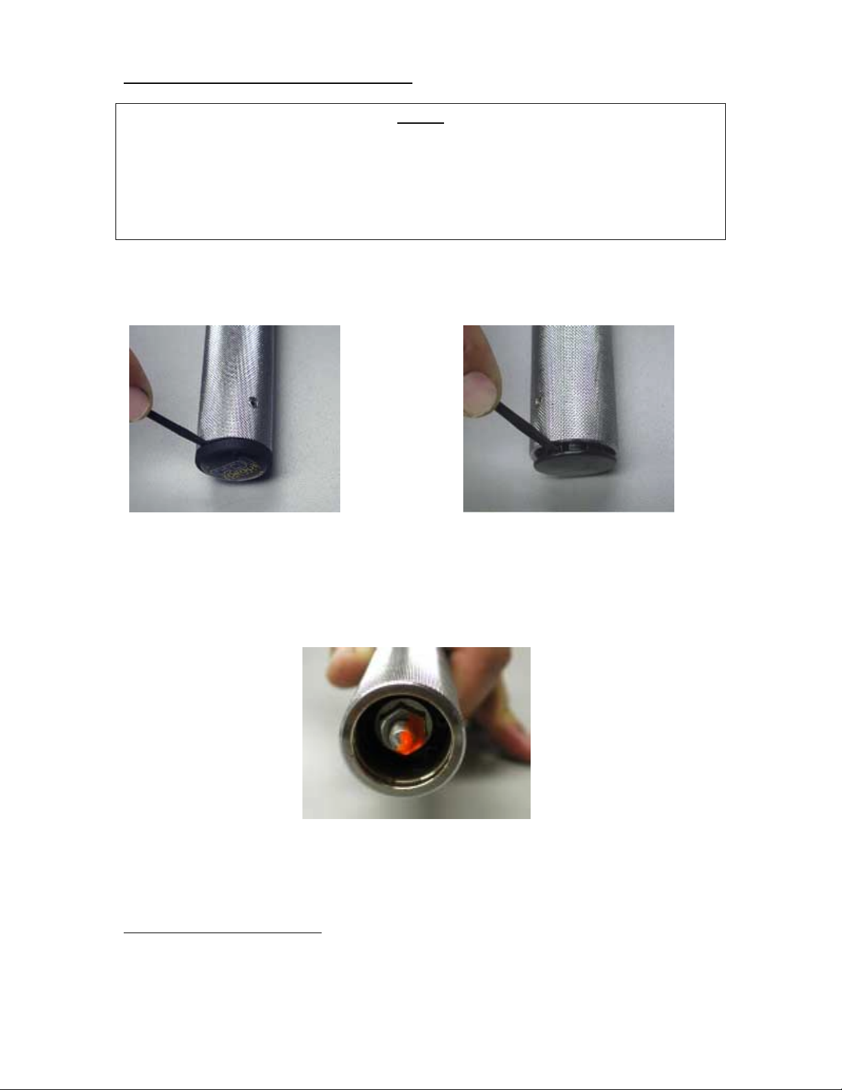
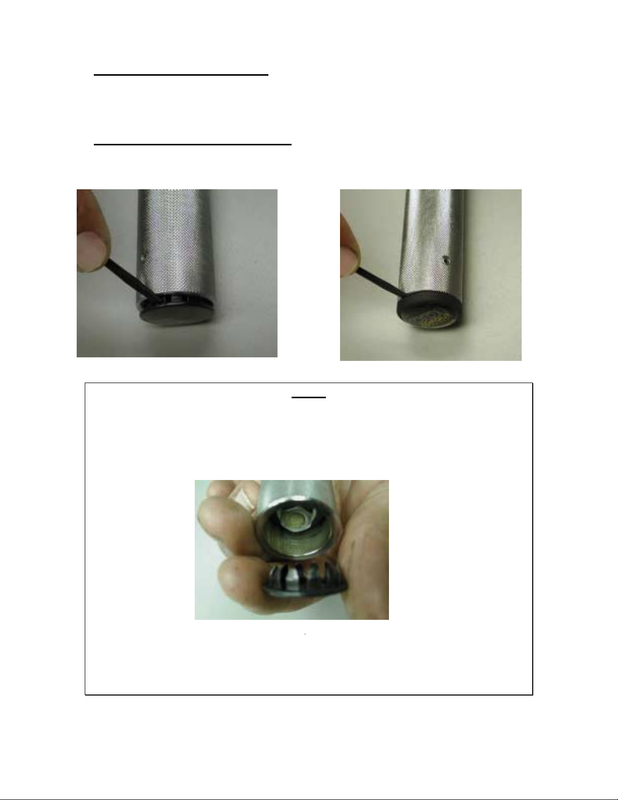
5. Set the handle at 120% of full scale. Remove the 2plug from the end of the handle.
OR
Plug Removal
6. Check the torque seal on the load screw. If removed or cracked, the wrench
calibration has been tampered with or the handle has been forced below its preset stop
point.
Handle End View
1
All torque wrenches with ¼” head drives must be calibrated at 100% of scale, not minimum (20%)
2
See section on handle/lock ri ng for particulars on button plug or FOD plug removal.
Page 6
Page 11

HANDLE/TUBE VIEW
7. Pull the lock ring down and turn the handle until you reach the desired reading on the
tester as follows:
A.
If the reading on the tester was below the accuracy limit for the value tested turn the
handle clockwise to increase the value. Release the lock ring. Repeat this test and
adjustment procedure until the torque reading is within the accuracy limits.
B. If the reading on the tester was above the accuracy limit for the value tested turn the
handle counterclockwise to decrease the value. Release the lock ring. Repeat this
test and adjustment procedure until the torque reading is within the accuracy limits.
Release the lock ring and check the value on the tester.
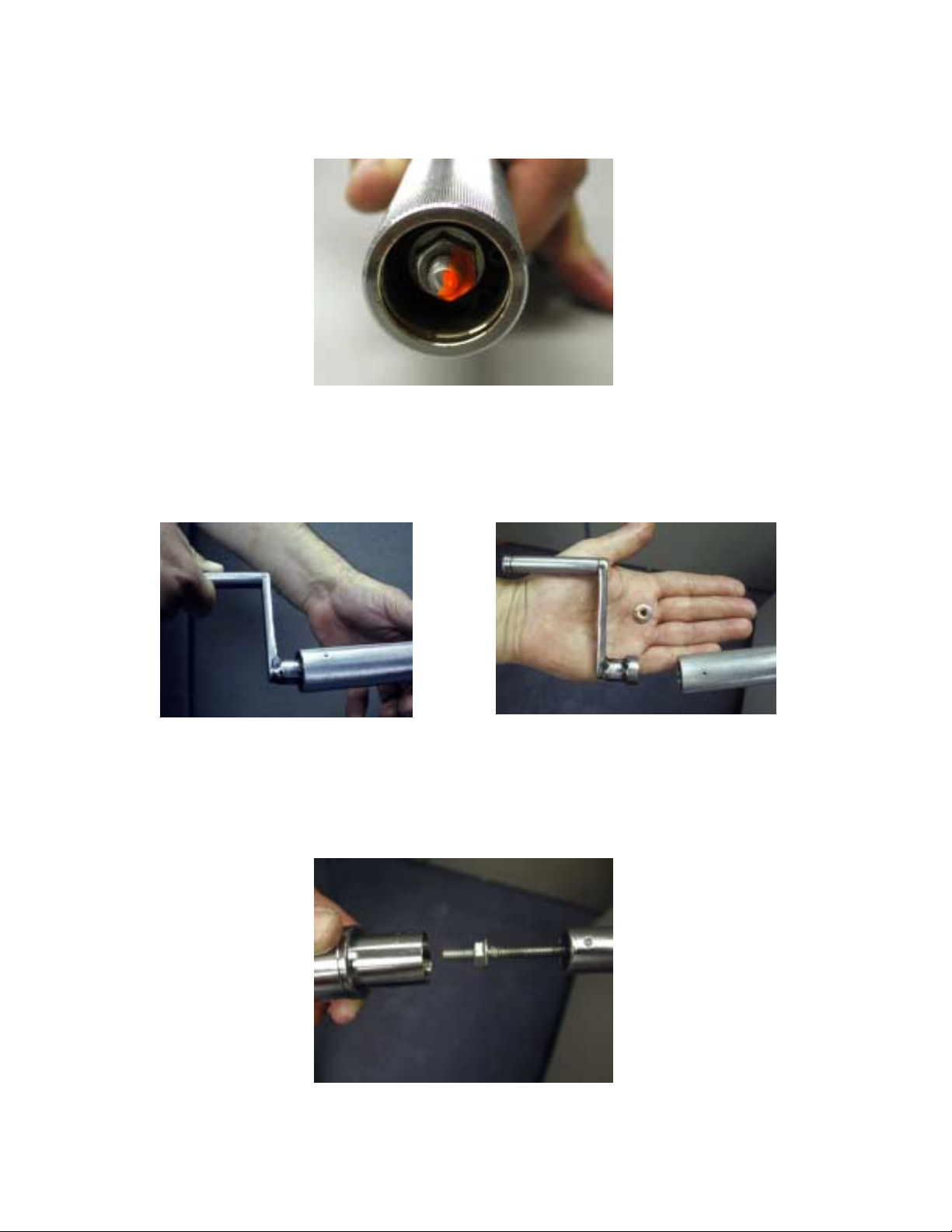
8. With the lock ring in the locked position and holding the wrench handle firmly to
prevent rotation of the handle, loosen the hex flange nut with the calibration crank
handle (approximately 2 full turns). Sometimes this will disengage the hex flange nut
from the screw and on other wrenches the hex flange nut will remain on the load
screw. The Torque seal will show a crack between the nut and screw. Remove the
loose torque seal from the nut and screw.
Loosening Nut
Page 7
Page 12

9. Pull the lock ring down, while applying a light force towards the wrench (to prevent
handle disengagement) and turn handle until handle “0” mark is aligned to the
centerline of the scale.
10. Tighten the hex flange nut (B) with a 200 in. lb. torque wrench as follows:
Handle Locking
Torque Wrench Ranges Hex Flange Nut Size Torque Ranges
50 in. lb. to 250 in. lb. 3/8” 35 to 40 in. lb.
75 ft. lb. to 1000 ft. lb. 7/16” 90 to100 in. lb.
11. Retest the wrench for accuracy (steps 1 through 4). If the wrench is not within
specified accuracy requirements repeat steps 5 through 10 or the wrench may require
a major calibration.
MAJOR CALIBRATION AND REPAIR
These instructions are to be used for the major calibration. Major calibration requires the
wrench to be partially disassembled from the front removing the ratchet or drive
mechanism, to inspect the internal component parts for contaminates, damage and/or
wear. Replacement parts are normally required. Each wrench model has an Exploded
Illustration that lists the component parts and shows assembly particulars. The exploded
illustration must be used as a guide for purchasing CDI Torque Wrench component parts.
Contact CDI Sales Department at (626) 965-0668 or sales@cditorque.com for
Exploded Illustrations for a particular torque wrench model and/or to purchase
component parts needed for repairs.
Page 8
Page 13

To disassemble the tube
1. Pull down the lock ring and unwind the handle of the wrench below 20% of scale
until it stops. This must be done to remove the pressure on the drive or ratchet head.
Prior to removal of the rivet and pivot pin required for a major calibration.
2. Remove the pivot pin rivet from the tube by using the modified end cutters. Push the
pivot pin out of the tube to release the head drive.
To recalibrate the wrench
1. Pull the head drive, secondary arm (if required), pawl and cam slowly out of the
wrench to prevent the pawl from 3loosing its orientation in the cam.
OR
3
If the pawl orientation in the slot of the cam is unknown rebuild the wrench without inserting the rivet
into the pivot pin and retest.
Page 9
Page 14

2. The orientation, size and style of the pawl in the wrench must be determined,
measured and noted so it can be found on the pawl selection chart. Use a micrometer
to measure the pawl and determine its
4
size and style.
3 A major recalibration requires the selection of a new pawl. To find the correct pawl,
locate the pawl removed from the wrench on the pawl selection chart. This is the
starting point for selecting a new pawl
Pawl Orientation Chart
O = Square Pawl
All sides are the same no orientation to pawl slot required.
ARM
T = Tall
Taller side of
the pawl is
CAM perpendicular
to the cam slot
ARM
S = Short
Shorter side of
The pawl is
CAM perpendicular
to the cam slot
4
Due to the machining tolerances, pawl sizes sometimes do not corresponding exactly to the number in the
pawl selection chart. If this occurs choose the pawl on the chart closest to the pawl removed from the
wrench.
Page 10
Page 15

Pawl Size
There are six different pawl sizes available for calibrati on starting with pawl number “0”
with square cross sections. Metric sizes (mm) are in parentheses ().
SIZE
STYLE
A B C
0 - .250 x .250
(6.35) x (6.35)
1 - .250 x .244
(6.35 x 6.20)
2 .260 x .250
(6.60 x 6.35)
3 .260 x .245
(6.60 x 6.20)
4 .260 x .240
(6.60 x 6.10)
5 .260 x .235
.250 x 240
(6.35 x 6.10)
.250 x .235
(6.35 x 6.00)
.250 x .230
(6.35 x 5.85)
- .187 x .168
(6.60 x 6.00)
Style Chart
= Pawl with longer side .260 (6.60)
A
= Pawl with longer side .250 (6.35) or both sides .250 (6.35)
B
= Pawl with longer side .187 (4.75) or both sides .187 (4.75)
C
NOTE: Style “C” is used on wrenches up to a maximum scale of .250 in. lb.
PAWL IDENTIFICATION CODE EXAMPLE
ARM
3 T B size 3 ==== .250 x .235
↓↓↓↓ ↓↓↓↓ ↓↓↓↓ (6.35 x 6.00)
⇓
↓↓↓↓ of pawl is
⇔⇔⇔⇔ .235 (6.00) orientation perpendicular
CAM to the pawl slot)
B ==== pawl with longer
Metric sizes (mm) are in parentheses ().
⇓ .250 (6.35) =
⇓⇓
= size ↓↓↓↓ style ==== T ==== tall (longer side
==
side .250 (6.35)
.187 x .187
(4.75 x 4.75)
.187 x .183
(4.75 x 4.65)
.187 x .180
(4.75 x 4.57)
.187 x .176
(4.75 x 4.47)
.187 x .173
(4.75 x 4.40)
(4.75 x 4.27)
Page 11
Page 16

PAWL SELECTION CHART
STYLE
♦♦♦♦
A
.260
(6.60)
or
B
.250
(6.35)
TO DECREASE THE READING⇐⇐⇐⇐----------------⇒⇒⇒⇒TO INCREASE THE READING
SIZE & ORIENTATION
5T
A⇓⇓⇓⇓
.235
(6.00)
⇔⇔⇔⇔
4T
A⇓⇓⇓⇓
.240
(6.10)
⇔⇔⇔⇔
B⇓⇓⇓⇓
.230
(5.85)
⇔⇔⇔⇔
3T
A⇓⇓⇓⇓
.245
(6.20)
⇔⇔⇔⇔
B⇓⇓⇓⇓
.235
(6.00)
⇔⇔⇔⇔
2T
A⇓⇓⇓⇓
.250
(6.35)
⇔⇔⇔⇔
B⇓⇓⇓⇓
.240
(6.10)
⇔⇔⇔⇔
1T
B⇓⇓⇓⇓
.244
(6.20)
⇔⇔⇔⇔
0
B⇓⇓⇓⇓
B
⇔⇔⇔⇔
1S
.244⇓⇓⇓⇓
(6.20)
B
⇔⇔⇔⇔
2S
.240⇓⇓⇓⇓
(6.10)
B
⇔⇔⇔⇔
3S
.235⇓⇓⇓⇓
(6.00)
B
⇔⇔⇔⇔
4S
.230⇓⇓⇓⇓
(5.85)
B
⇔⇔⇔⇔
5S
Style C .187 (4.75)
for wrenches with a maximum scale up to 250 in. lb. ONLY.
♦♦♦♦
C⇓⇓⇓⇓
.168
(4.27)
⇔⇔⇔⇔
C⇓⇓⇓⇓
.173
(4.40)
⇔⇔⇔⇔
C⇓⇓⇓⇓
.176
(4.47)
⇔⇔⇔⇔
C⇓⇓⇓⇓
.180
(4.57)
⇔⇔⇔⇔
C⇓⇓⇓⇓
.183
(4.65)
⇔⇔⇔⇔
C⇓⇓⇓⇓
C
⇔⇔⇔⇔
.183⇓⇓⇓⇓
(4.65)
C
⇔⇔⇔⇔
.180⇓⇓⇓⇓
(4.57)
C
⇔⇔⇔⇔
.176⇓⇓⇓⇓
(4.47)
C
⇔⇔⇔⇔
.173⇓⇓⇓⇓
(4.40)
C
⇔⇔⇔⇔
.168⇓⇓⇓⇓
(4.27)
C
⇔⇔⇔⇔
NOTES
To increase or decrease the torque reading approximately 2% requires changing the
actual pawl size one location.
Always select a pawl to the left ⇐⇐⇐⇐ of the actual pawl to decrease the wrench reading.
Always select a pawl to the right ⇒⇒⇒⇒ of the actual pawl to increase the wrench
reading.
There is an overlapping of pawl sizes. Style “A’” and “B” overlap from size 2T to
4T. Use style “A”
Metric sizes (mm) are in parentheses ().
, if available
.
Page 12
Page 17

EXAMPLE #1
The wrench reads approximately 5% low from nominal. Disassemble the wrench and
measure the pawl. It was .260 (6.60)⇓ X .245 (6.20)⇔, orientated with the longer side of
the pawl perpendicular to the cam slot. To find the correct pawl, locate the pawl removed
from the wrench on the pawl selection chart. This pawl is number 3TA on the chart. This
is the starting point for selecting a new pawl.
To increase the reading of the wrench 4% choose the pawl two places to the right of 3TA
(.260 (6.60)⇓ X .245 (6.20)⇔) which is 1TB (.250 (6.35)⇓ X .244 (6.20)⇔). This pawl
change should increase the wrench reading to within approximately 1% of nominal.
PAWL SELECTION CHART
STYLE
♦♦♦♦
5T
4T
3T
SIZE & ORIENTATION
Metric sizes (mm) are in parentheses ().
2T 1T
0
1S
2S
3S
4S
5S
.260
(6.60)
or
.250
(6.35)
A
B
A⇓⇓⇓⇓
.235
(6.00)
⇔⇔⇔⇔
A⇓⇓⇓⇓
.240
(6.10)
⇔⇔⇔⇔
B⇓⇓⇓⇓
.230
(5.85)
⇔⇔⇔⇔
A⇓⇓⇓⇓
✷✷✷✷
✷✷✷✷
.245
(6.20)
⇔⇔⇔⇔
B⇓⇓⇓⇓
.235
(6.00)
⇔⇔⇔⇔
A⇓⇓⇓⇓
.250
(6.35)
⇔⇔⇔⇔
B⇓⇓⇓⇓
.240
(6.10)
⇔⇔⇔⇔
.B⇓⇓⇓⇓
.244
(6.20)
⇔⇔⇔⇔
.B⇓⇓⇓⇓
B
⇔⇔⇔⇔
.244⇓⇓⇓⇓
(6.20)
B
⇔⇔⇔⇔
.240⇓⇓⇓⇓
(6.10)
B
⇔⇔⇔⇔
.235⇓⇓⇓⇓
(6.00)
B
⇔⇔⇔⇔
.230⇓⇓⇓⇓
(5.85)
B
⇔⇔⇔⇔
Page 13
Page 18

EXAMPLE #2
The wrench reads approximately 5% high from nominal. Disassemble the wrench and
measure the pawl. It was .250 (6.35)⇓ X .244 (6.20)⇔, orientated with the longer side of
the pawl perpendicular to the cam slot. To find the correct pawl, locate the pawl removed
from the wrench on the pawl selection chart. This pawl number is 1TA on the chart. This
is the starting point for selecting a new pawl.
To decrease the reading of the wrench 4% choose the pawl two places to the left of 1TB
(.250 (6.35)⇓ X .244 (6.20)⇔) which is 3TA (.260 (6.60)⇓ X .245 (6.20)⇔) or 3TB
(.250 (6.35)⇓ X .235 (6.00)⇔).
The recommended change would be to a Style “A”, if available. This pawl change should
decrease the wrench reading to within approximately 1% of nominal.
PAWL SELECTION CHART
STYLE
♦♦♦♦
5T
4T
3T
SIZE & ORIENTATION
Metric sizes (mm) are in parentheses ().
2T 1T
0
1S
2S
3S
4S
5S
.260
(6.60)
or
.250
(6.35)
A
B
A⇓⇓⇓⇓
.235
(6.00)
⇔⇔⇔⇔
A⇓⇓⇓⇓
.240
(6.10)
⇔⇔⇔⇔
B⇓⇓⇓⇓
.230
(5.85)
⇔⇔⇔⇔
A⇓⇓⇓⇓
✷✷✷✷
✷✷✷✷
.245
(6.20)
⇔⇔⇔⇔
B⇓⇓⇓⇓
.235
(6.00)
⇔⇔⇔⇔
A⇓⇓⇓⇓
.250
(6.35)
⇔⇔⇔⇔
B⇓⇓⇓⇓
.240
(6.10)
⇔⇔⇔⇔
B⇓⇓⇓⇓
.244
(6.20)
⇔⇔⇔⇔
B⇓⇓⇓⇓
B
⇔⇔⇔⇔
.244⇓⇓⇓⇓
(6.20)
B
⇔⇔⇔⇔
.240⇓⇓⇓⇓
(6.10)
B
⇔⇔⇔⇔
.235⇓⇓⇓⇓
(6.00)
B
⇔⇔⇔⇔
.230⇓⇓⇓⇓
(5.85)
B
⇔⇔⇔⇔
4. Check the pawl and pawl slot for worn or damaged edges. Choose the appropriate
pawl to increase⇒ or decrease⇐ the reading.
5. Go to page 15 and follow instructions 4 through 9 to calibrate.
OR
6. To disassemble, clean, inspect and re-lubricate go to page 14 and follow instructions
1 though 9.
Page 14
Page 19
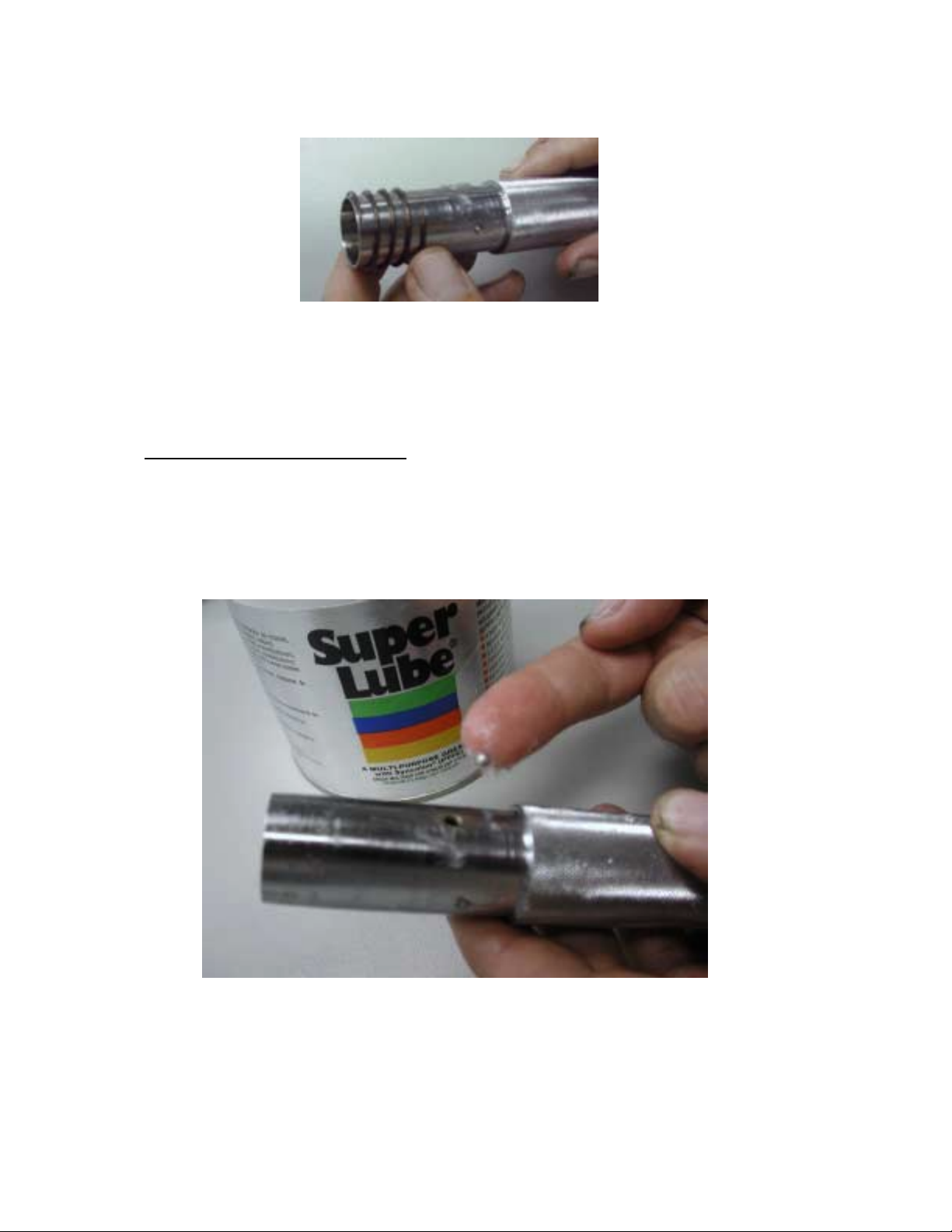
To Disassemble and Check Parts
1. Rem ove all part s from t ube. Ex ami ne them for wear and/or dam age. Replace parts
as required. Clean and lubricate internal parts with Super Lube.
2. Assemble the parts according to the assembly blueprint requirements (spacers,
Thrust washers, flat washers & spring). Slide into the tube.
Page 15
Page 20

3. Place the cam on top of the spring, properly orientated to the pivot hole.
4. Select pawl as shown on pages 9 through 13. Lightly grease the pawl to hold it
into position in the cam. Place the pawl in the cam slot.
.
5. Place th e end of the drive head or arm carefully against the top of the pawl and
slide assembly back into the tube. Place pivot pin through the tube and head.
Page 16
Page 21

CAUTION
The wrench must always be assembled with some positive pressure on the spring. To
assure positive pressure, the pivot hole of the head must be pushed into alignment with
the pivot hole on the tube. Failure to assemble the wrench with positive pressure will
result in the wrench not being able to hold calibration.
To check for positive pressure on the spring
a) Place the pivot pin into the assembled wrench.
b) With the handle unwound to its lowest point (the handle stop), the wrench should be
at 5% to 10% of full scale (example a 250 ft/ lb. wrench should read 12.5 to 25 ft. lb.)
on a torque tester.
c) If the wrench does not click or reads below at 5% of full scale on a torque tester when
the handle is at its lowest position, disassemble and add more washers to increase the
pressure.
6. Pull the lock ring down and adjust the wrench up to the maximum scale value.
Cycle the wrench a minimum of 25 times in both directions (clockwise &
counterclockwise).
7. Pull the lock ring down and adjust the wrench down to minimum scale value.
8. Perform an accuracy verification and if required, a minor calibration adjustment.
9. After calibration, insert a new rivet into the pivot pin. Use a hammer to lock rivet
into pivot pin.
Page 17
Page 22
HANDLE/LOCK RING REPAIR
These instructions are to be used for the repair of the handles or lock rings. Calibration
does not require the handle to be disassembled.
To Disassemble the Handle/Lock Ring
1. Remove the button or rubber plug with a flat blade mini screwdriver.
NOTE
There are two distinct end plugs for the torque wrenches.
They are:
• Steel button plug with a prongs, which requires 4 drops of adhesive (locktite 495) at
the top, bottom and sides.
⇐Steel Button
• Rubber plug that requires a groove inside of the handle end for installation.
A steel button plug may be placed into a handle end with a groove on the inside diameter.
A rubber plug may not be used on a handle without a groove on the inside of the handle.
Page 18
Page 23
2. Remove the Torque Seal from the screw and nut.
3. To disassemble the handle from the tube, remove the nut from the end of the wrench
using the calibration crank handle.
4. Next, remove the washer.
5. Pull the lock ring back to the unlock position (this releases the two balls from the
splines on the tube) and pull the handle off the tube.
Page 19
Page 24
NOTE
There are two distinct metal handle styles for the CDI torque wrenches.
They are:
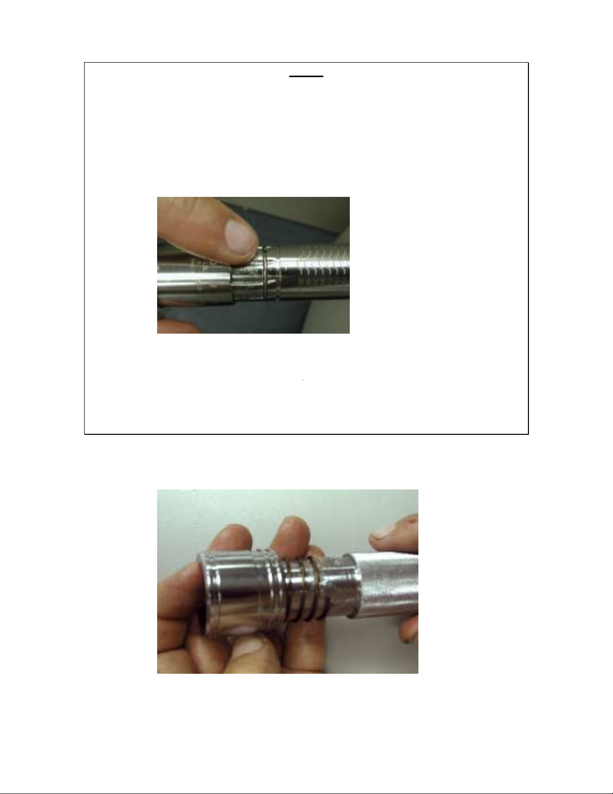
• A handle without a plastic bushing in the front. This model requires that the grooves
in the tube (between the splines and roll marking) have a spring rings in it. These are
wrenches that are from a maximum scale of 50 in. lb. to 250 in. lb
Spring Rings in tube
• A handle with a plastic bushing in the front. This handle requires the removal of the
spring ring from the groove in the tube (between the splines and roll marking).
6. Remove the lock ring from the handle.
Page 20
Page 25
7. Remove the lock ring spring.
8. Remove the two small round balls (held with Super Lube to handle) from the inside
of the handle.
To assemble the handle/lock ring
1. Place Super Lube on the ball holes on handle. Place two balls in holes (Super Lube
will hold them in place).
Page 21
Page 26

2. Next, place lock ring spring on handle
3. Place lock ring on handle.
4. Pull the lock ring down into the unlock position while sliding the handle as far as it
will go onto the tube. Turn the handle until the six point flange nut on the load screw
is engaged into the handle’s twelve point insert. Release the lock ring to engage the
balls into the splines on the tube.
Page 22
Page 27

5. Next, set the handle on the lowest increment of the tube. Pull the lock ring down to
the unlock position and turn the handle until the top of the handle scale is lined up
with the lowest increment on the tube. Release the lock ring to engage balls into the
splines on the tube.
NOTE
The top of the handle must touch the increment line on the tube scale. When “0” is set,
the top of the handle cannot cover up the increment line on the tube scale or be below it.
6. If the center line of the tube is not lined up with the “0” on the handle, pull down on
the lock ring to unlock it, pull the handle back off of the flange nut on the tube screw
(approx. ¼”). Turn the handle to reset the flange nut into the handle insert so that the
“0” is lined up with the centerline of the tube scale. Release the lock ring and jiggle
the handle lightly left and right until the lock ring is fully engaged.
NOTE
Wrenches with maximum ranges from 50 in. lb. to 250 in. lb. require a lock washer on
the handle (see exploded illustration for lock washer part number). Do not reuse the lock
washer. Use a new lock washer when reassembling the handle to the tube.
7. Tighten the hex flange nut with a 200 in. lb. torque wrench as follows:
Page 23
Page 28

)
Handle Locking
Torque Wrench Ranges Hex Flange Nut Size Torque Ranges
50 in. lb. to 250 in. lb. 3/8” 35 to 40 in. lb.
75 ft. lb. to 1000 ft. lb. 7/16” 90 to 100 in. lb.
8. An accuracy and minor calibration adjustment must be performed after a handle is
assembled.
CALIBRATION INSTRUCTIONS FOR PRE-SET TORQUE WRENCHES
Pre-Set Torque Wrenches
REPAIR TOOLS REQUIRED
1 3/32” “T” Handle hex
1 CDI Adjusting Tool (see chart for correct part number)
LOCKING
PIN (6)
RECEPTACLE (3)
INTERCHANGEA
BLE HEAD (5)
HAND GRIP
ADJUSTING SCREW (4
BUTTON
PLUG (2)
LOCKING SCREW (1)
PRE-SET TORQUE WRENCH
1. Loosen locking screw (1) with the 3/32” T handled hex.
2. Remove Button Plug (2) from rubber handle end by bending a corner of the handle
end until the edge of the plug appears. Then remove the plug by lifting the edge.
3. Insert the interchangeable head (5) into the wrench receptacle until the locking pin (6)
is fully engaged with the corresponding receptacle hole (3).
NOTE
Some heads used in pre-set torque wrenches have lengths that vary. It is recommended
that pre-set torque wrenches be calibrated with the head that is to be used to assure the
greatest accuracy in calibration.
Page 24
Page 29

4. Place the wrench on a torque tester and turn adjustment screw (4) with a T handled
hex ( 1/8” or 3/32”) until the desired setting is on the torque tester when a load is
applied.
CDI Pre-Set (Click) Torque Wrench Ranges & Adjustment Tool Part Numbers
Part
Number
Torque Ranges Adjustment
Tool
Part #
in./ft. lb. dNM/NM. cmkg/mkg
5T-I 16-60 in. lb. 14-67 dNM 14-69 cmkg 600-45-01 3/32”
10T-I 36-108 in. lb. 40-122 dNM 42-124 cmkg 600-45-02 1/8”
10ST-I 84-300 in. lb. 95-338 dNM 110-385 cmkg 600-45-02 1/8”
10AT-I 84-300 in. lb. 95-338 dNM 110-385 cmkg 600-45-03 1/8”
50ST-I 10-50 ft. lb. 14-67 NM. 1.4-7 mkg. 600-45-03 1/8”
50T-I 10-50 ft. lb. 14-67 NM. 1.4-7 mkg. 600-45-03 1/8”
100ST-I 30-150 ft. lb. 41-200 NM. 4.1-20 mkg. 600-45-04 1/8”
100T-I 30-150 ft. lb. 41-200 NM. 4.1-20 mkg. 600-45-04 1/8”
200T-I 40-200 ft. lb. 55-270 NM. 5.5-27 mkg. 600-45-04 1/8”
300T-I 60-300 ft. lb. 82-400 NM. 8.2-40 mkg. 600-45-05 3/16”
600T-I 200-600 ft. lb. 275-800 NM. 27.5-135 mkg. 600-45-06 3/16”
5. Tighten the locking screw (1). Test wrenches setting three more times. If the readings
are correct, place torque seal into the locking screw (1) hex opening to prevent
tampering.
6. Place button plug (2) back into the handle end by inserting it into one side of the
opening then applying pressure with your finger until it is fully engaged.
TROUBLESHOOTING
The Pre-Set Torque Wrenches generally do not require repair. They are sent in for
calibration to the required use setting with the head or adapter chosen for use. All
adjustments are to be made as shown in the section on Pre-Set Torque Wrench
Calibration.
The Troubleshooting Matrix is for the Micrometer Adjustable Wrench models only.
Refer to the Troubleshooting Matrix for problems that could occur to the Micrometer
Adjustable Torque Wrenches and their remedy.
Hex
Size
Page 25
Page 30

Micrometer Adjustable Torque Wrench
Troubleshooting Matrix
PROBLEM CAUSE(s) REMEDY
Calibration accuracy at
20% of scale is out of
tolerance.
OR
Calibration accuracy at
20%, 60% and 100% of
scale is out of tolerance.
OR
Calibration accuracy at
60% and 100% of scale
is out of tolerance
When the lock ring is
released the handle goes
up and down the tube
without turning the
handle or the handle
doesn’t turn at all.
Handle and load screw
disassembled.
Lock Ring Doesn’t
Lock.
Lock ring is jammed or
doesn’t fall into lock
Wrench tampered with
(torque seal cracked or
missing)
OR
The handle is unwound below
the stop point. (torque seal
cracked or missing)
Check handle prior to adjusting to assure it is engaged to the adjusting screw.
Minor calibration
Adjustment.
OR
Handle disassembled handle
and reassembled wrong.
(torque seal cracked or
missing)
OR
If a minor calibration fails
to bring the 20% of scale
reading into tolerance or if
adjustment causes the 60%
or 100% of scale to fall out
of the tolerance a major
calibration is required.
Pawl and/or pawl slots worn or
damaged.
NOTE
NOTE
OR
NOTE
Check pawl and pawl slots
prior to a major calibration.
A major calibration.
The tube insert is stripped
Send to authorized repair
facility.
OR
No lubrication on torque load
screw.
See handle/lock ring repair
section to assemble.
The handle was turned without
releasing the lock ring. (the
Send to authorized repair
facility.
tube will show groove marks
through the splines)
Handle spring problem. Disassemble the
handle/lock ring and replace
Page 26
Page 31

position when released. lock ring spring.
PROBLEM CAUSE(s) REMEDY
The wrench does not
click.
The pawl is not in the pawl
slot.
OR
There is no pressure on the
pawl.
Disassemble wrench and
add washers to increase
pressure on pawl.
NOTE
When placing the
ratchet/head drive into the
tube to insert the pivot pin,
the drive pivot hole must be
pushed into the tube to align
the holes.
If there is no pressures
remove parts and add more
washers to increase pressure
on the pawl.
The wrench only clicks
in one direction or can
only be calibrated in one
direction.
The head drive and/or
secondary arm (if used) are not
in centerline.
Replace the head drive
and/or secondary arm (if
used).
The pawl double clicks. Check and replace as
needed head and/or
secondary arm (if used).
Check and replace the pawl,
as needed.
Page 27
 Loading...