


SURETEST AND 600TL
Model 5000-3
Torque Calibration System
USER’S MANUAL

TABLE OF CONTENTS
|
|
|
Safety Information |
I |
|
Introduction |
1-1 |
|
Functional Description and Specifications |
2-1 |
|
Functional Descriptions |
2-1 |
|
SURETEST Torque Calibration System |
2-1 |
|
Base Unit |
2-2 |
|
• |
Front Panel |
2-2 |
• |
Rear Panel (Input/Output) |
2-9 |
Torque Transducers |
2-11 |
|
Specifications |
2-12 |
|
SURETEST Torque Calibration System |
2-12 |
|
• |
SURETEST Base Unit |
2-12 |
• |
Transducers |
2-13 |
• |
600TL (LOADER) |
2-14 |
Setup and Programming |
3-1 |
|
SURETEST Torque Calibration System Setup |
3-1 |
|
Back panel connections |
3-1 |
|
Setting Up the SURETEST System |
3-2 |
|
SURETEST Base Unit Controls |
3-3 |
|
Powering the Equipment |
3-3 |
|
Transducer Select |
3-4 |
|
Programming Setup |
3-5 |
|
• Setting up Date and Time |
3-5 |
|
• Setting Up High and Low Limits Alert |
3-5 |
|
• |
Programming AUTO Settings |
3-6 |
DATA LIST Memory |
3-7 |
|
• Clear single memory location |
3-8 |
|
• Clear all memory location |
3-8 |
|
Setting Up Printer/PC Ports |
3-8 |
|
Torque Calibration System Setup |
4-1 |
|
Testing Torque Wrenches and Drivers |
4-1 |
|
Selecting a Transducer |
4-1 |
|
Installing a Transducer |
4-1 |
|
Dial and Bending Beam Torque Wrenches and Screwdrivers |
4-2 |
|
Adjustable or Preset “Click” Wrenches and Screwdrivers |
4-3 |
|
Testing Power Tools |
4-4 |
|
Non-Impact Tools |
4-4 |
|
Statistical Analysis |
4-7 |
|
• Displaying Statistical Analysis on LCD |
4-7 |
|
• |
Printing Statistical Analysis |
4-8 |
Displaying or Downloading Data List |
4-10 |
|
How to Use Analog Output (Rear Panel BNC Connector) |
4-11 |
|
Calibration |
5-1 |
|
Mounting Details |
5-1 |
|
Quick Check |
5-4 |
|
Torque Transducer Calibration |
5-7 |
|
TABLE OF CONTENTS 1

SURETEST Base Unit Calibration |
5-11 |
Gravitational Effects |
5-14 |
Correction Factors on Test Weights |
5-14 |
Gravitational Charts |
5-15 |
600TL Manual Loader |
6-1 |
Application |
6-1 |
Torque Tester/Calibrator |
6-2 |
Types of Loader Testing |
6-5 |
• Torque Driver Testing |
6-5 |
Accessories |
A-1 |
SURETEST System Components and Inventory Control |
A-1 |
Optional Transducers and Accessories |
A-2 |
Calibration Accessories |
A-4 |
TABLE OF CONTENTS 2

Using this Manual
This manual contains instructions for use and setup of the SURETEST 5000-3 Torque Calibration System. A table of contents and a table of illustrations are provided to make this manual easy to use.
Some of the information shown in text or illustrations is obtained using optional equipment.
Conventions
This section contains a list of conventions used in text.
Chapter References
Additional information in text is referenced by chapter number and section name.
Example:
For testing procedures refer to Chapter 4—Using the SURETEST 5000-3
System.
Equipment Damage
The possibility of damage to vehicle or equipment is introduced by a signal word indicating this condition.
Example:
IMPORTANT
The connector on single transducer cables contains the EEPROM calibration memory chip. Never attempt to remove the connector from the transducer. It is installed with a permanent adhesive.
Safety Messages
Safety messages are provided to help prevent personal injury and equipment damage. All safety messages are introduced by a signal word indicating the hazard level. The types of safety messages are: Danger, Warning and Caution.
TABLE OF CONTENTS 3

DANGER
Indicates an imminently hazardous situation which, if not avoided, will result in death or serious injury to the operator or to bystanders.
WARNING
Indicates a potential hazard which, if not avoided, could result in death or serious injury to the operator or to bystanders.
CAUTION
Indicates a potential hazard which, if not avoided, may result in minor or moderate injury to the operator or to bystanders.
The three-part message panel, used with safety messages, uses three different type styles to further define the potential hazard:
•Normal type states the hazard,
•Bold type states how to avoid the hazard, and warning.
•Italic type states the possible consequences of not avoiding the hazard.
Some safety messages contain visual symbols with signal words.
Example:
WARNING
Flying particles can discharge when applying torque.
•Users and bystanders must wear safety goggles.
•Always wear safety goggles when applying torque.
Flying particles can cause injury.
TABLE OF CONTENTS 4

SAFETY INFORMATION
Safety Information
Important Safety Instructions
This manual contains important safety and operating instructions for CDI 5000-3 Torque Calibration System. Refer to the information in this manual often for safe operation.
Read All Instructions
Read, understand and follow all safety messages and instructions in this manual and on the test equipment. Safety messages in this section of the manual contain a signal word, a three-part message.
The signal word indicates the level of hazard in a situation:
•Danger indicates an imminently hazardous situation which, if not avoided, will result in death or serious injury to the operator or bystanders.
•Warning indicates a potentially hazardous situation which, if not avoided, could result in death or serious injury to the operator or bystanders.
•Caution indicates a potentially hazardous situation which, if not avoided, may result in moderate or minor injury to the operator or bystanders.
The three-part message uses three different type styles to further define the potential hazard.
•Normal type states the hazard.
•Bold type states how to avoid the hazard.
•Italic type states the possible consequences of not avoiding the hazard.
SAVE THESE INSTRUCTIONS
WARNING
Risk of electric shock and fire.
•For indoor use only. Do not expose charger to rain or snow. Do not use in damp locations.
•Replace defective cord immediately. Return to qualified service center for replacement. Electric shock or fire can cause injury.
WARNING
Flying particles can discharge when applying torque.
•Users and bystanders must wear safety goggles.
•Always wear safety goggles when applying torque.
•Do not use this equipment with the power off. Always turn on the indicator and loader
-I -

SAFETY INFORMATION
so the torque and load values are indicated on the display. The safety relays only work when the power is on. Flying particles can cause injury.
WARNING
Risk of entanglement.
•When starting power tools, check for obstacles near your hand and anticipate the reaction force by gripping the tool firmly.
•Do not wear loose clothing and jewelry while operating a power tool. Loose clothes and jewelry can be caught in moving parts.
•Keep body parts away from rotating parts.
•Wear a protective hair covering to contain long hair and prevent contact with moving parts.
•Do not overreach. Keep proper footing and balance at all times. Entanglement can cause injury.
WARNING
Improper use can cause breakage.
•Read instructions before operating.
•Follow manufacturer’s instructions, safety precautions, and specifications when operating tools. Broken equipment can cause injury.
WARNING
•Make sure all components, including adaptors, extensions, drivers and sockets are rated to match or exceed the torque or load being applied.
•Be sure the capacity of the 5000-3 system matches or exceeds each application before performing a procedure.
•Do not use the 5000-3 system if it makes unusual noises, has loose parts, or shows any other sign of damage. Have repairs performed at a CDI Service Center before use.
•Do not use chipped, cracked, or damaged sockets and accessories.
•Do not remove any labels. Replace any damaged label.
•Follow good, professional tool practices:
**Pull on a wrench handle ** do not push ** and adjust stance to prevent a possible fall.
**Do not use extensions, such as a pipe, on a wrench handle.
•When using ratchets, make sure the direction lever is fully engaged in the correct position.
•Never attempt to test an impact tool on this instrument.
•Always position the 40" arm over the front of the stand as shown. Never extend the test arm behind the stand. The stand will tip over when weights are applied.
•Always be alert to the potential for personal injury that may be caused by excessive torque applications, careless handling of heavy weights, and out-of-balance or unsafe weight distribution.
- II -

INTRODUCTION |
CHAPTER 1 |
CHAPTER 1
Introduction
The SURETEST is a laboratory grade instrument that provides TORQUE measurements. Although designed as an independent digital indicator, it can also be used in an integrated environment as the principal component of a Torque Calibration System. The SURETEST features versatile data acquisition capabilities including measurement storage, retrieval, statistical analysis and automatic downloading to an external printer/computer. A remote computer COM port is available for PC interfacing.
Used with precision torque transducers, the SURETEST provides high speed monitoring of static or dynamic torque inputs. Torque transducers, purchased separately, are available in ranges from 15-200 in.oz, to 2002000 ft.lb. and provide system readings with an accuracy of ± 0.25% of indicated value, or better. A special memory chip is built into each torque transducer that identifies its range and maintains its calibration between any other SURETEST with an accuracy of ± 0.5%. The SURETEST and its transducers may be calibrated by using accessory precision bars and certified weights.
All readout of torque in ft-lb, in-lb, in-oz, Nm, dNm, cNm, mkg as well as calibration, statistical analysis and set-up functions are reported on a versatile 1.5” x 5.5” graphic dot matrix Liquid Crystal Display (LCD).
Set-up and calibration programming is entered using easy-to-use front panel membrane keys. The number of keys is kept to a minimum. In addition, concise menus and graphic symbols are used to guide the user through all set-ups and operations. HIGH and LOW torque limits are adjustable to give an audible alert. The user selects TRACK mode to display torque values as they are applied, PEAK HOLD or POWER TOOL modes to display the highest torque value applied, or FIRST PEAK mode which captures the torque output at the “click” of a set-able wrench or driver. CLEAR, STORE and SEND functions can be set up for automatic or manual operation.
The SURETEST stores and recalls up to 3000 torque readings and does statistical analysis on them for downloading to printer or computer. The statistical report (print out) includes a simple histogram for process monitoring. True RS-232 serial printer and separate RS-232 computer COM ports are at the back of the unit.
1-1

INTRODUCTION |
CHAPTER 1 |
The SURETEST operates directly from any AC power line between 100 VAC to 230 VAC, 50–60 Hz without the need for switch selection. A hard-wired lithium battery keeps the internal memory and date-time clock operating for up to 10 years. The real time clock is fully year 2000 compliant.
The information in this manual is general. Operational features, procedures and specifications may change without notice. CDI Torque Products makes no claims as to the suitability of this information for diverse user applications.
1-2
FUNCTIONAL DESCRIPTION AND SPECIFICATIONS |
CHAPTER 2 |
|
|
CHAPTER 2
Functional Description and Specifications
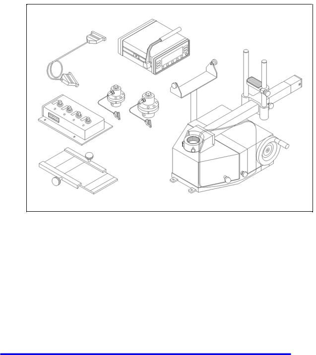
The CDI 5000-3 is CDI’s next generation Torque Measurement System. It provides exceptional accuracy and ease of use. It is packaged in a compact, sturdy and attractive housing unit which requires little room on a laboratory bench. The SURETEST is typically used in conjunction with a Transducer and a 600TL bench top Mechanical Loader.
Fig 2-1
Base Unit
The SURETEST monitors and displays the torque applied.
Transducer (Accessory)
The loader accepts all 2000 series single transducers directly. Use a 2000-500-02 adapter kit to mount the 2000-400-02 4-in-1 transducer. For additional information refer to Appendix A–Accessories.
Loader
Use the 600TL Manual Loader for testing and calibrating all torque wrenches, drivers, torque multipliers, non-impact pneumatic and electric nut runners. Loader components are:
•Safety Shield
•Hand Crank
•Transducer Mounting
2-1
FUNCTIONAL DESCRIPTION AND SPECIFICATIONS |
CHAPTER 2 |
|
|
SURETEST BASE UNIT
Front Panel
Figure 2-2 SURETEST Front Panel
A- Membrane Function ( F1, F2, F3, F4, F5, F6 ), soft keys,
and Cursor/Selection (Up (↑), Down (↓),Left (←), Right (→) and Enter ( ) Keys. B- Soft Key Menu: Zero, # Data Stored, Setup, Send, Store, Clear, Escape, Format.
C- Real Time Clock. HH:MM:SS
D- Modes: Track, Peak Hold, First Peak and Power tools.
E- Maximum Range of Transducer.
F- Engineering Units : Nm, dNm, Ncm, mkg, cmkg, ft. lb., in. lb., in.oz
G- Power: On/Off
H- Bar Graph: Each dot represents 10% of transducer full scale.
I- Torque Reading: Full 5-digit reading Plus Sign (for direction)
2-2
FUNCTIONAL DESCRIPTION AND SPECIFICATIONS |
CHAPTER 2 |
|
|
Display
A 240 x 64 Full-featured Graphic LCD is used to provide versatile and clear displays of system menus as well as measurements. Characters and symbols are displayed in different fonts:
•Maximum transducer range in the selected UNITS of measure.
•The number of the present data memory location.
Front Panel Membrane Cursor and Function Keys
The SURETEST is supported by a powerful Graphic User Interface (GUI). Set up, Command, or Control is done by selecting the appropriate Action Item on one of the provided Menus. Front Panel Membrane Cursor and Functions keys are defined to guide the User in selecting an Action Item.
There are 6 function (soft) keys: F1 through F6. Their respective uses are clearly indicated on the LCD.
To select an Action Item, the User simply presses a Function Key (F1-F6) to get to a Menu, uses a Cursor Key to move to the Item, then hits ‘ENTER’ .
In addition to the ‘ENTER’ key, there are 4 Cursor Keys : Up (↑), Down (↓),, Left (←), Right (→). The GUI also provides Prompts to further assist the user in navigating the Menus.
Power Up Sequence
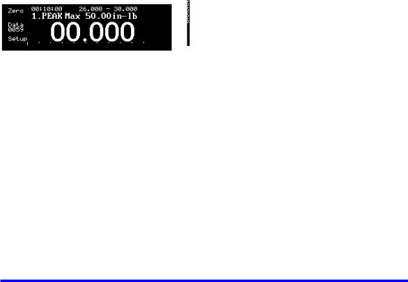
Upon power up, the SURETEST automatically performs Self-tests and displays the results. Any detected non-functional hardware will be reported on the LCD. If a 4-in-1 transducer is connected, the SURETEST performs ZEROTARE, then displays the following default menu while continuously checking for any activity from an input transducer :
The user can either press F1 to display previously collected data (if any) or enter Setup Mode, F2. Any detected torque measurement will cause the SURETEST to enter Measurements mode where the following menu is displayed:
2-3
FUNCTIONAL DESCRIPTION AND SPECIFICATIONS |
CHAPTER 2 |
|
|
The SURETEST returns to the default menu from the measurements mode in the event there is no selection / input by the User for more than two minutes. This serves as a reminder for more (input) measurements.
Setup Mode
The following Selections are available:
1.SELECT MODE
2.SELECT UNIT
3.SELECT LANGUAGE
4.MANUFACTURER’S DEFAULTS
5.AUTO SETTINGS
6.EDIT LIMITS
7.CLOCK ADJUST
8.CALIBRATION
9.EDIT PARAMETERS
10.INTERNAL DIAGNOSTIC
11.ABOUT
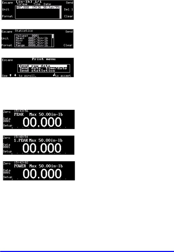
1.Select Mode
Selects either TRACK, PEAK HOLD, FIRST PEAK, or POWER mode.
•TRACK : continually makes Torque Measurements.
• PEAK : makes Torque Measurement at the Highest Peak.
•1.PEAK : makes Torque Measurement at the First Peak.
•POWER : makes Torque Measurement at the Highest Peak at a faster rate.
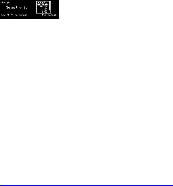
2.Select Unit
Selects the following Torque units on LCD display:
Nm, dNm, cNm, mkg, cmkg, ft. lb., in. lb., in. oz.
2-4

FUNCTIONAL DESCRIPTION AND SPECIFICATIONS |
CHAPTER 2 |
|
|
3.Select Language
Selects either English, German (Deutsch), French (François), Spanish (Español).
4.Manufacturer’s Defaults:
Default: Min. Track 0.1% ; Min. Peak 1%.
A warning message is first displayed. Upon confirmation by the User, the Default Settings will be loaded into the SURETEST.
5.Auto Settings
Sets up CLEAR, STORE, and SEND functions. There are 2 options: Automatic or Manual.
Selection: Automatic Clear, Automatic Store and Automatic Send data out (to RS-232 port). Selection: Delay 9 seconds then clear the Display, Manual Store and Manual Send.
Selection: Automatic Clear, Automatic Store and Manual Send.
2-5

FUNCTIONAL DESCRIPTION AND SPECIFICATIONS |
CHAPTER 2 |
|
|
6.Edit Limits
Sets up high torque limit preset. (-->) (F4) to go Down 1 line. Sets up low torque limit preset. (<--) (F5) to go Up 1 line.
Use Up or Down cursor key to increment or decrement the respective value. Use Left (←) or Right (→) cursor key to select digit.
Press ‘Save’ (F2) to activate the change. Press ‘Clear” (F1) to Clear All Limit set-up. Press ‘Escape’ (F3) to Exit. Last setup is retained.
7.Clock Adjust
Edits DATE/TIME programming function.
To adjust the Clock, use Left (←) or Right (→) cursor key to get to Day, Month, Year, Hour, Minute, or Second field. Then use Up (↑), Down (↓), cursor key to increment or decrement the respective value.
Press and hold the cursor key to change the value quickly. Press ‘ENTER’ to activate the change.
8.Calibration
This enables the User to perform calibration of the SURETEST base unit and transducers. (Refer to chapter 5).
2-6
FUNCTIONAL DESCRIPTION AND SPECIFICATIONS |
CHAPTER 2 |
|
|
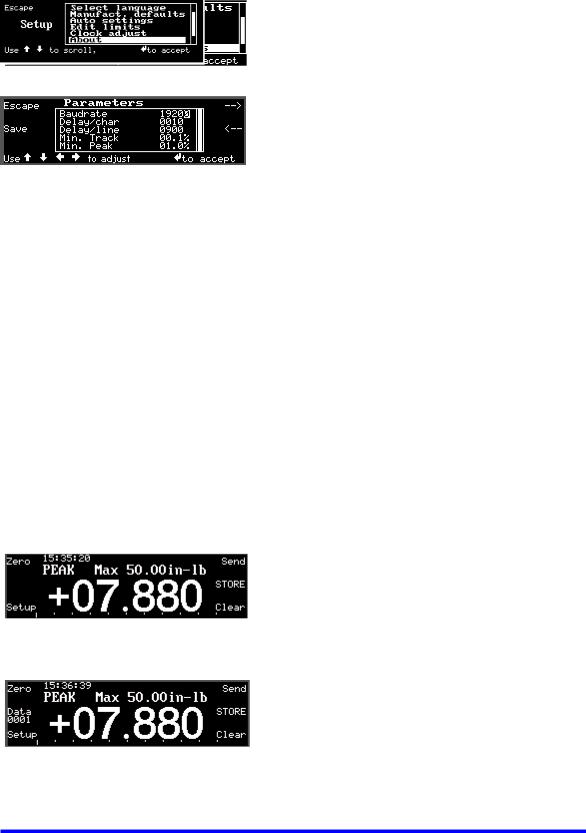
9.Edit Parameters
Sets up serial communications protocol.
Sets delay (in ms) per character upon printing.
Sets delay (in ms ) per Linefeed.
Minimum block-out with zero at 0.1% F.S. in Tracking Mode.
Minimum block-out with zero at 1.0% F.S. in Peak-Hold Mode.
10.Internal Diagnostic
For Manufacturer’s use only.
11.About
This provides relevant information regarding the Manufacturer, the software version, and the serial number of the SURETEST device.
12.Other Features:
Provides manual ZERO TARE.
Stores present measurement to memory (Data 0001 in the example below).
2-7
FUNCTIONAL DESCRIPTION AND SPECIFICATIONS |
CHAPTER 2 |
|
|
Sets up memory clear options in RECALL mode.
Recalls memory data to display.
Format (F3) calls Statistical analysis to display.
Send (F4). Send data to printer.
Sends all memory data, statistical analysis and histogram to printer port.
Sends data list with or without date-time stamp to computer / printer.
Manually clears display in PEAK, FIRST PEAK, POWER TOOL modes.
2-8

FUNCTIONAL DESCRIPTION AND SPECIFICATIONS |
CHAPTER 2 |
|
|
SURETEST BASE UNIT
Rear Panel (Input/Output)
Figure 2-3 SURETEST Rear Panel
A - Solenoid Control (Hirose RM15TRD-12S)
(for use with optional 2000-600-02 Loaders)
PIN FUNCTION
10Loader Relay Common
11Loader Relay CCW Limit
12Loader Relay CW Limit
B - Analog Output (BNC)
Analog output provides a voltage level output that is directly proportional to transducer input, from -1.8V (full scale counter clockwise) to +1.8V (full scale clockwise). Zero offset +/-100 mV. Linearity +/-1% of reading. Maximum load = 5 mA.
When using the 4-in-1 transducer, zero output fluctuates until one of the transducers is scan selected by applying 5% of full scale torque.
C - Foot Pedal Switch Input
(used to send output to printer)
D - Fuse Holder
Use AC fuse at specified rating only. ( 3.15 Amp).
E - Input AC Voltage
Automatic Selection of any AC voltage from 100VAC to 230VAC, 50-60 Hz, 50 W.
2-9

FUNCTIONAL DESCRIPTION AND SPECIFICATIONS |
CHAPTER 2 |
|
|
F- PRINTER PORT (DB-9P) |
|
PIN FUNCTION
2Receive
3Transmit
5 Ground
G- OPTIONAL (DB-9P)
PIN FUNCTION
2Receive
3Transmit
5 Ground
H- TRANSDUCER INPUT (DB-37S)
PIN FUNCTION
1not used
2ground
3smart chip - bit 2
4smart chip - bit 0
5single xducer (-) signal
6single xducer (+) signal
7ground
84-in-1 xducer (-) signal 2
94-in-1 xducer (+) signal 2
10ground
114-in-1 xducer (-) signal 4
124-in-1 xducer (+) signal 4
134-in-1 xducer LED 2
144-in-1 xducer LED 4
15loader relay CW limit
16not used
17not used
18ground
19bridge excitation (+3V)
20not used
21smart chip - bit 3
22smart chip - bit 1
23ground
24ground
254-in-1 xducer (-) signal 1
264-in-1 xducer (+) signal 1
27ground
284-in-1 xducer (-) signal 3
294-in-1 xducer (+) signal 3
30no transducer
314-in-1 xducer LED 1
324-in-1 xducer LED 3
33loader relay CCW limit
34loader relay common
35Vcc (+5V@100 ma. max)
36ground
37bridge excitation (+3V)
2-10

FUNCTIONAL DESCRIPTION AND SPECIFICATIONS |
CHAPTER 2 |
|
|
SURETEST Transducers
SURETEST transducers provide industry standard square drives. They feature a full bridge strain-gauge @ 350 Ohms nominal. Full range output is 1500 uE, 9mV
(3mV/V @ 3.0V excitation).
Torque transducers use a built-in EEPROM memory chip that stores range identification and calibration factors. Calibration of transducers is accomplished using precision torque bars and certified weights. For additional information, refer to Chapter 5—Calibration.
After a transducer is calibrated, it provides ±0.5% system accuracy with any SURETEST System. If the transducer and SURETEST are calibrated together, the system accuracy increases to ±0.25%.
Transducer Dimensions/Transducer Torque Range
(Refer to table on page 2-13).
Display Resolution for Transducers
Calibration also results in a specified display resolution on the SURETEST. Display resolution is dependent on the type of transducer being used. Display resolutions for the specified transducer are shown on page 2-14.
SURETEST torque transducers can withstand an overload of 110% of full range. The SURETEST alarms, (audible beep and display “OVER” ) at 110% of rated capacity.
To protect the tool under test or to serve as a fastener installation torque preset alert, the SURETEST produces a constant audible tone when the input torque exceeds the SET LOW limit. It then produces a pulsating tone when the input torque exceeds the SET HIGH limit.
The SURETEST Base Unit ignores inputs less than 0.1% of full range in TRACK mode, 1% in PEAK HOLD mode, 7% in FIRST PEAK and POWER TOOL modes.
With the 4-in-1 transducers, the SURETEST System ignores inputs less than 1% of full range after scan select.
2-11
FUNCTIONAL DESCRIPTION AND SPECIFICATIONS |
CHAPTER 2 |
|
|
Specifications
SURETEST TORQUE CALIBRATION SYSTEM Specifications
System Accuracy
±0.25% of reading @ 25°C with SURETEST Base Unit and transducer calibrated together. (SURETEST Transducers used with, but not calibrated to, another SURETEST Base Unit provide a system accuracy of ±0.5% of reading @ 25°C.
Temperature Drift +0.03%/°C (+0.017%/°F).
Display
5.5” X 1.5” backlighted LCD graphics display, 240x64 dot matrix., 0.67” torque digits character height.
Display Capacity
16 bit A/D, 5 digits ±32,000 counts. Sample rate, 2000 sample/sec., display rate 5 updates/sec. Refer to transducer range & resolution charts on page 2-13 and 2-14.
Language Select
English, German, French and Spanish.
Bar Graph
Zero to transducer full-scale. Resolution, 10 major divisions, 100 minor divisions.
Units of measure
Ft. lb., in. lb., in. oz., Nm, dNm, cNm, mkg, cmkg.
(Refer to transducer range and resolutions charts on pages 2-13 and 2-14.
Measurement Modes
Track, Peak Hold, First Peak, Power Tool.
Keypad
Sealed membrane keypad with audible feedback featuring “Softkey” user interface.
Features: Zerotare; Mode, Units and Language select; High and Low limits setup; Auto Store, Clear and Send select; Clock adjust; Calibration; and RS232 programming.
Data Storage/Recall with Date-Time Stamp.
3,000 measurements
Remote contact, (optional foot pedal) manual send to printer.
Statistical Analysis
Max, Min, Range, Mean, Sigma N, Sigma, Cp, Cpk, %Error, Go, Nogo, Printout Histogram.
Serial Output Ports
Printer, RS232 True, 300-19.2k Baud, 8 data bit, 1 stop bit, no parity, (default 9600 Baud). Optional Computer COM port, as above, (default 19.2k Baud).
Analog Output
+(CW), -(CCW) 1.8V at transducer full range. Linearity ±1% of reading, ±100mV zero offset.
Loader Control Relays
Two, normally open, from rated 12VDC@1/2A close contact at 110% CW or CCW of torque transducer range, and release at 105% (open contact). (For use with optional 2000600 Manual Loader)
2-12
 Loading...