


MULTITEST Motorized Loader
USER'S MANUAL
MOTORIZED CONTROL LOADER
Torque-Angle Tutorial
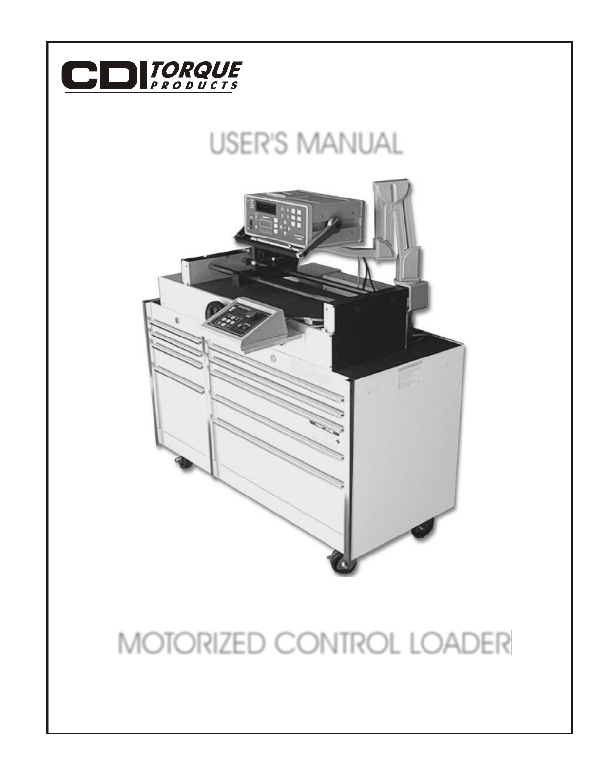
Torque vs Load
Today’s torque wrenches are very accurate.
Unfortunately, torque can be a poor
parameter to measure when you’re really
interested in controlling load. As shown in
the Torque vs Loadgraph at left, 120
Newton-meters of torque applied to a dry
and corroded bolt only produces 7,000
pounds of clamping load in a sample joint.
This same bolt, cleaned and lubricated,
results in nearly 21,000 pounds of load for
the same 120 Nm applied. That’s 14,000
lbs of uncertainty.
The torque applied to a fastener (bolt or
screw) is absorbed in three main areas.
Over half of the total torque is lost to
underhead friction. About a third of the
torque is absorbed by the fastener threads.
This leaves about 10 percent of the applied
torque that actually develops into clamping
load which holds a bolted assembly
together. Unless the frictional forces have
been carefully predetermined and controlled
in some way, such as with special lubricants
or expensive joint preparation, torque will
never consistently relate to tightness.
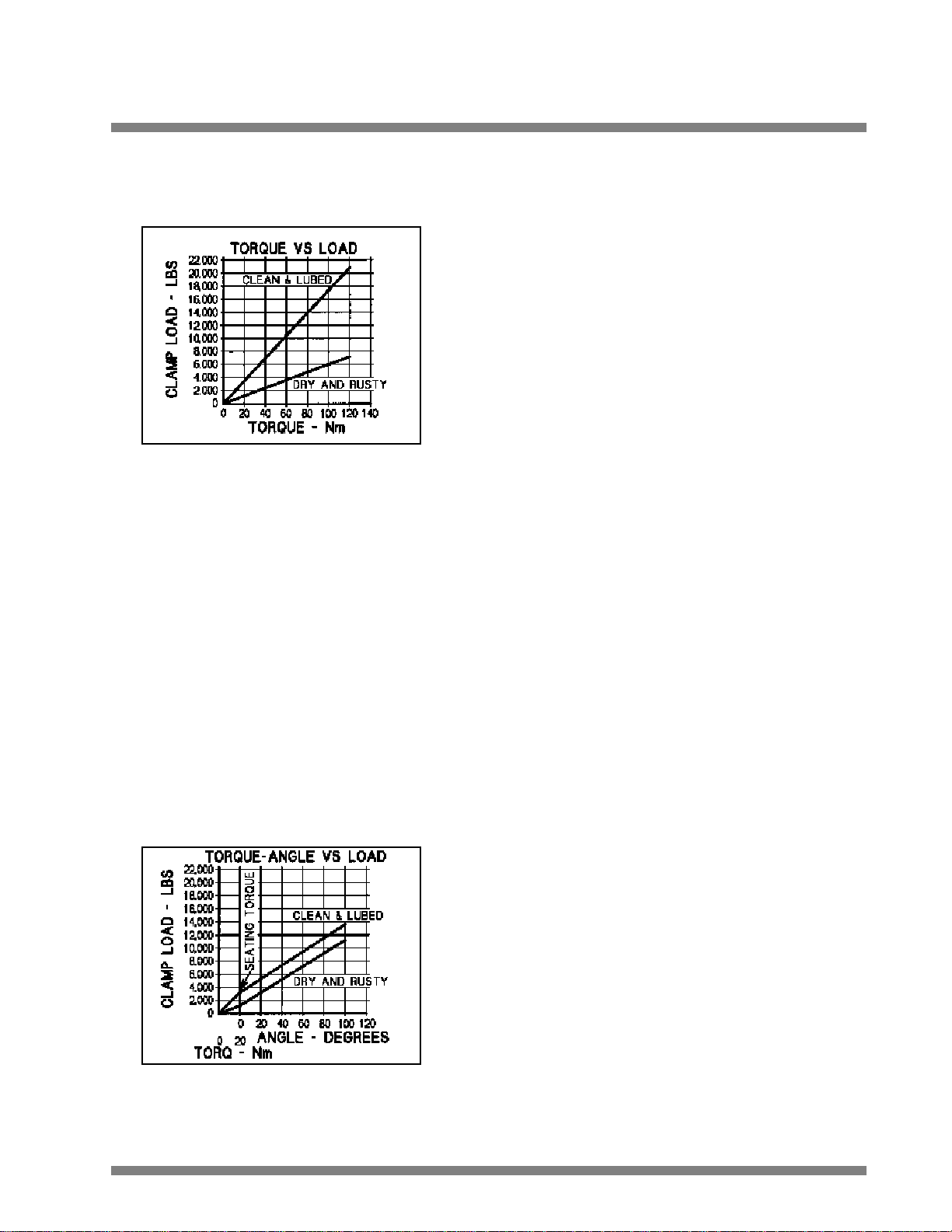
Torque-Angle vs Load
When a fastener is installed, it stretches.
This stretch (bolt tension) can be calculated
very accurately by using the bolt length,
slope of the threads (threads per inch) and
fastener turns (degrees of rotation). As
shown in the Torque-Angle vs Loadgraph at
left, once seated, rotation is directly related
to load regardless of bolt condition. In this
case, a small torque is used to seat the
fastener and 100 degrees of rotation
produces the required 12,000 lbs of load
with less than 2,000 lbs of uncertainty.
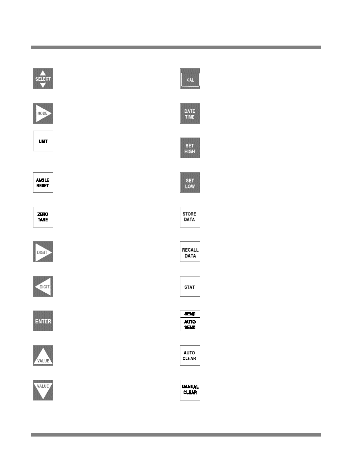
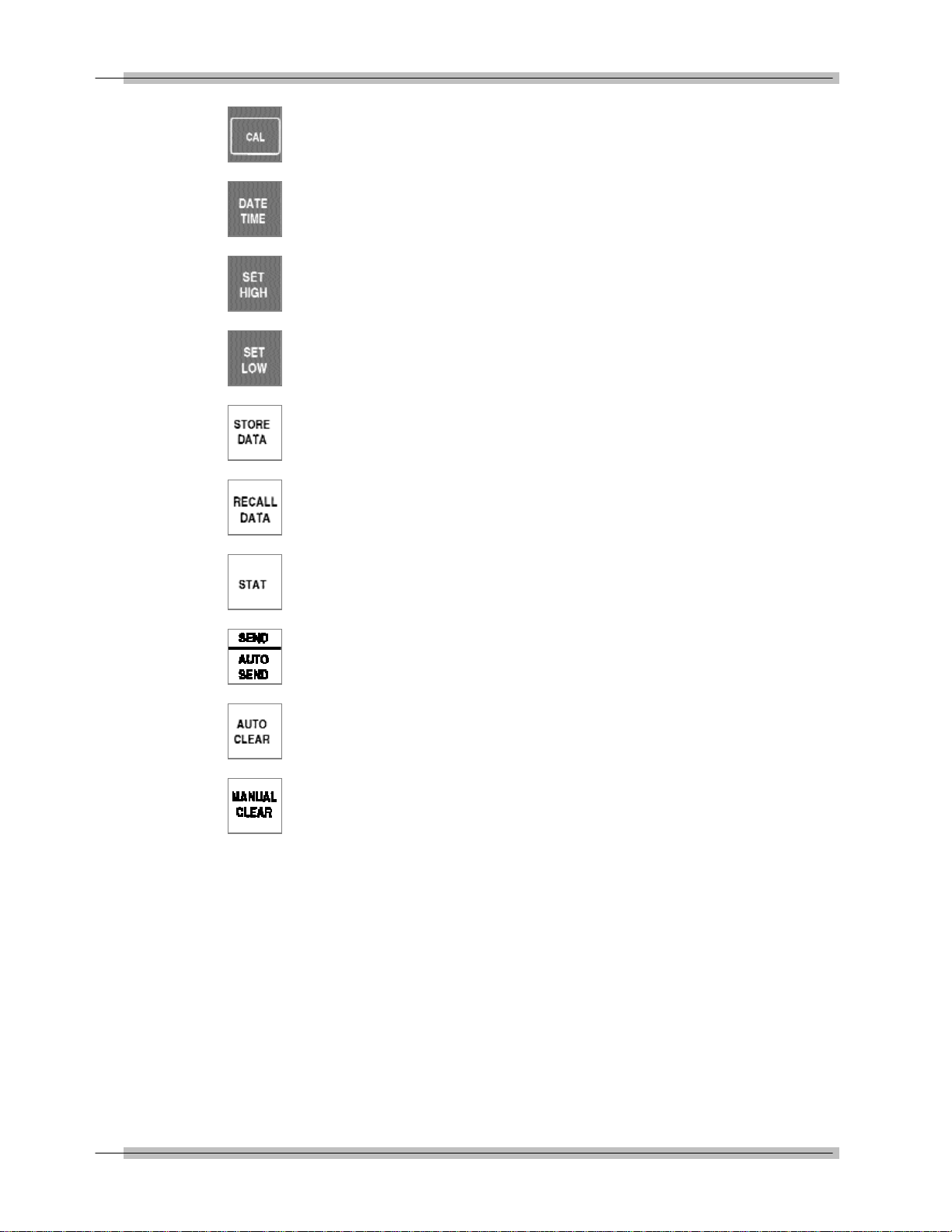
Front Panel Function Keys
Toggles between TORQUE and FORCE
measurement modes.
Selects TRACK, PEAK HOLD, POWER
TOOL, FIRST PEAK and ANGLE modes.
Selects following units on LCDdisplay:
Torque units in: Nm, dNm, cNm, mkg,
cmkg, lb ft, in lb, in oz, or
Force units in: N, dN, kp, gf,lbf, oz.
Manually resets ANGLE display on LCD.
Manually resets ZERO TARE.
Opens and terminates calibration mode.
Edits DATE/TIME programming function.
Sets up high torque/force limit preset. Set
up angle preset in torque-angle mode.
Sets up low torque/force limit preset. Set
up clamping torque preset in torque-angle
mode.
Stores present measurement to memory.
Selects LED or LCD digit to right (blinking)
for setup and programming. Shift for
printer and angle encoder programming.
Selects LED or LCD digit to left (blinking)
for setup and programming. Shift for
printer and angle encoder programming.
Terminates calibration and program
modes. Returns to 4-in-1 transducer scan.
Increments selected digit during calibration
and program modes. Scrolls statistical
analysis display.
Decrements selected digit during
calibration and program modes. Scrolls
statistical analysis display.
Recalls memory data to display.
Sends all memory data, statistical analysis
and histogram to printer/port.
Sends data list with or without date-time
stamp to computer printer. Sets up serial
protocol function.
Sets up CLEAR, STORE, and SEND
modes function.
Manually clears display in PEAK, FIRST
PEAK, POWERTOOL and ANGLE modes.
Sets up memory clear options in RECALL
mode.

Table of Contents
Safety Information ...................................................................................................................... I
Introduction ............................................................................................................................ 1-1
Functional Description and Specifications ............................................................................ 2-1
Functional Descriptions ..............................................................................................................2-1
Motorized Control Loader System ........................................................................................2-1
2000-810-01 Indicator ..........................................................................................................2-3
Front Panel ....................................................................................................................2-3
Rear Panel (Input/Output) ..............................................................................................2-7
MULTITEST Torque/Force Transducers ..........................................................................2-9
Specifications .......................................................................................................................... 2-11
MOTORIZED CONTROL LOADER System .................................................................. 2-11
2000-810-01 Indicator .................................................................................................. 2-11
Torque/Force Transducers ............................................................................................ 2-13
Setup and Programming .......................................................................................................... 3-1
Motorized Control Loader System Setup ..............................................................................3-1
Setting Up the Motorized Control Loader System ............................................................3-2
2000-810-01 Indicator Controls ..............................................................................................3-3
Powering the Equipment ......................................................................................................3-4
4-in-1 Transducer Select ................................................................................................3-4
Programming Setup ..............................................................................................................3-5
Setting up Date and Time ..............................................................................................3-5
Setting Up High and Low Limits Alert ..............................................................................3-6
Programming AUTO CLEAR ..........................................................................................3-7
DATA LIST Memory ........................................................................................................3-9
Setting Up Printer/PC Ports ................................................................................................ 3-11
Selecting Printer/PC Ports ............................................................................................ 3-11
Setting Up Serial Communications ................................................................................ 3-12
Encoders ............................................................................................................................ 3-13
Setting Up Angle Encoders .......................................................................................... 3-13
Setting Up Torque-Angle Measurement Modes .................................................................. 3-15
Setting Up the Torque/Angle Algorithm .......................................................................... 3-15
Setting Angle Only Measurements ................................................................................ 3-16
Using the Multitest Torque Calibration System ...................................................................... 4-1
Testing Torque Wrenches and Drivers ..................................................................................4-1
Selecting a Transducer ..................................................................................................4-1
Installing a Transducer ....................................................................................................4-1
Dial and Bending Beam Torque Wrenches and Screwdrivers ..........................................4-2
Adjustable or Preset “Click” Wrenches and Screwdrivers ................................................4-3
Testing Power Tools ..............................................................................................................4-5
Non-Impact Tools ............................................................................................................4-5
Measuring Force, Compression and Tension ..................................................................4-7
Displaying Statistical Analysis ..............................................................................................4-8
Displaying Statistical Analysis on LCD ............................................................................4-9
Printing Statistical Analysis .......................................................................................... 4-10
Displaying or Downloading Data List ............................................................................ 4-11
Displaying Data List on LCD ........................................................................................ 4-11
i

Table of Contents
Downloading Data List to Printer .................................................................................. 4-11
Downloading Data List to Personal Computer .............................................................. 4-12
How to Use Analog Output (Rear Panel BNC Connector) .............................................. 4-13
Measuring Torque and Angle .............................................................................................. 4-14
Torque Only .................................................................................................................. 4-14
Angle Only .................................................................................................................... 4-15
Torque-Angle Algorithm ................................................................................................ 4-16
Calibration ................................................................................................................................ 5-1
Calibration Equipment ..........................................................................................................5-1
Mounting Details ............................................................................................................5-2
Quick Check ........................................................................................................................5-5
Torque/Force Calibrations ....................................................................................................5-8
MULTITEST Torque/Force Transducer Calibration ........................................................5-8
2000-810-01 Indicator Torque/Force Calibration ..............................................................5-8
Gravitational Effects ............................................................................................................5-11
Correction Factors on Test Weights .............................................................................. 5-11
Gravitational Charts ...................................................................................................... 5-11
2000-800-02 Motorized Loader ................................................................................................ 6-1
Application ............................................................................................................................6-1
Functional Description ..........................................................................................................6-2
Specifications ................................................................................................................6-2
Torque Tester/Calibrator ..................................................................................................6-3
2000-800-02 Motorized Loader ......................................................................................6-3
Ball Handle Adaptor ........................................................................................................6-6
4-in-1 Transducer (Accessory) ........................................................................................6-8
Extension Arm (Accessory) ............................................................................................6-9
Motorized Control Box ..........................................................................................................6-9
Loader Rear Panel Interconnect .......................................................................................... 6-11
Using the Motorized Controller ............................................................................................ 6-12
Click Wrench Testing .................................................................................................... 6-13
Dial,Beam or Screw Driver Testing ................................................................................ 6-16
Task Termination/Cancellation ...................................................................................... 6-19
Manual Mode ................................................................................................................ 6-21
Types of Loader Testing ...................................................................................................... 6-22
Torque Driver Testing .................................................................................................... 6-22
Torque Multiplier Testing .............................................................................................. 6-22
Force Testing ................................................................................................................ 6-23
Accessories ..............................................................................................................................A-1
Motorized Control System Components and Inventory Control ............................................A-2
Optional Transducers and Accessories ................................................................................A-3
Calibration Accessories ........................................................................................................A-5
ii

Table of Illustrations
Functional Description and Specifications ............................................................................ 2-1
Figure 2-1: Motorized Loader Control System ......................................................................2-1
Figure 2-2: Roll Cabinet Drawer Layout ..............................................................................2-2
Figure 2-3: 2000-810-01 Front Panel ..................................................................................2-3
Figure 2-4: Maximum Range Display ..................................................................................2-4
Figure 2-5: 2000-810-01 Rear Panel ..................................................................................2-7
Setup and Programming .......................................................................................................... 3-1
Figure 3-1: Motorized Control Loader Setup ........................................................................3-1
Figure 3-2: Indicator Controls ..............................................................................................3-3
Figure 3-3: Date and Time Display ......................................................................................3-5
Figure 3-4: AUTO CLEAR, STORE, SEND Display ..............................................................3-7
Figure 3-5: RECALL Data Display ........................................................................................3-9
Figure 3-6: RECALL Data Display ........................................................................................3-9
Figure 3-7: Encoder Count Display .................................................................................... 3-14
Figure 3-8: Clamping Torque Display ................................................................................ 3-15
Figure 3-9: Edit Angle Display .......................................................................................... 3-16
Using the MULTITEST Calibration System .............................................................................. 4-1
Figure 4-1: Power Tool Test Setup ......................................................................................4-6
Figure 4-2: Statistical Analysis Display ................................................................................4-9
Figure 4-3: Value Display ....................................................................................................4-9
Figure 4-4: Sample Statistical Data Printout ...................................................................... 4-10
Figure 4-5: Data Download Display .................................................................................... 4-11
Figure 4-6: Angle Mode Display ........................................................................................ 4-15
Calibration ................................................................................................................................ 5-1
Figure 5-1: 4 in 1, Wheel, Butterfly, hook and hanger ..........................................................5-1
Figure 5-2: Single Low Torque Transducer Mounting Detail ................................................5-2
Figure 5-3: Single High Torque Transducer Mounting Detail ................................................5-3
Figure 5-4: 4-in-1 Transducer Mounting Detail ....................................................................5-4
2000-800-02 Motorized Loader ................................................................................................ 6-1
Figure 6-1: 2000-800-02 Motorized Loader ..........................................................................6-3
Figure 6-2: 2000-800-02 Motorized Loader, Exploded View ................................................6-4
Figure 6-3: Ball Handle Adaptor ..........................................................................................6-6
Figure 6-4: 4-in-1 Transducer on 2000-800-02 Motorized Loader ........................................6-7
Figure 6-5: 2000-800-02 Motorized Loader Extension Arm ..................................................6-8
Figure 6-6: MCB Front Control Panel ..................................................................................6-9
Figure 6-7: 2000-800-02 Motorized Loader Rear Panel Interconnect .................................. 6-11
Accessories ..............................................................................................................................A-1
Figure A-1: Roll Cabinet Drawer Arrangement ....................................................................A-1
iii

Using this Manual
This manual contains instructions for use and setup of the
Motorized Control Loader System . A table of contents and a
table of illustrations are provided to make this manual easy to
use.
Some of the information shown in text or illustrations is obtained
using optional equipment.
Conventions
This section contains a list of conventions used in text.
Check Note
A check note provides additional information about the subject
in the preceding paragraph.
Example:
System capabilities include, data storage, retrieval,
statistical analysis and automatic downloading to a
printer or computer.
Chapter References
Additional information in text is referenced by chapter number
and section name.
Example :
For testing procedures refer to Chapter 4—Using the
Multitest Torque Calibration System.
Equipment Damage
The possibility of damage to vehicle or equipment is introduced
by a signal word indicating this condition.
Example :
The connector on single transducer cables contains
the EEPROM calibration memory chip. Never
attempt to remove the connector from the
transducer. It is installed with a permanent
adhesive.
iv
Using This Manual
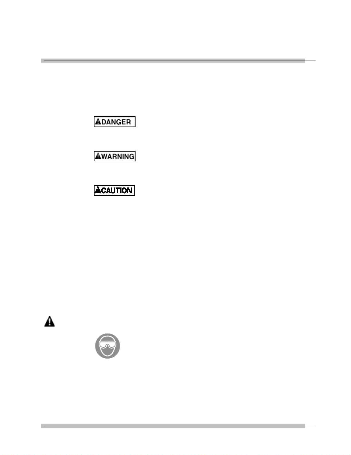
Safety Messages
Safety messages are provided to help prevent personal injury
and equipment damage. All safety messages are introduced by
a signal word indicating the hazard level. The types of safety
messages are:
Indicates an imminently hazardous situation which,
if not avoided, will result in death or serious injury
to the operator or to bystanders.
Indicates a potential hazard which, if not avoided,
could result in death or serious injury to the
operator or to bystanders.
Indicates a potential hazard which, if not avoided,
may result in minor or moderate injury to the
operator or to bystanders.
WARNING
The three-part message panel, used with safety messages,
uses three different type styles to further define the potential
hazard:
• Normal type states the hazard,
• Bold type states how to avoid the hazard, and
• Italic type states the possible consequences of not avoiding
the hazard.
Some safety messages contain visual symbols with signal
words.
Example:
Flying particles can discharge when applying torque.
• Users and bystanders must wear safety goggles.
• Always wear safety goggles when applying torque.
Flying particles can cause injury.
v

Safety Information
IMPORTANT SAFETY INSTRUCTIONS
This manual contains important safety and operating
instructions for CDI Motorized Control Loader Torque System.
Refer to the information in this manual often for safe operation.
Read All Instructions
Read, understand and follow all safety messages and
instructions in this manual and on the test equipment. Safety
messages in this section of the manual contain a signal word, a
three-part message, and, in some instances, an icon.
The signal word indicates the level of hazard in a situation:
• Danger indicates an imminently hazardous situation which, if
not avoided, will result in death or serious injury to the
operator or bystanders.
• Warning indicates a potentially hazardous situation which, if
not avoided, could result in death or serious injury to the
operator or bystanders.
• Caution indicates a potentially hazardous situation which, if
not avoided, may result in moderate or minor injury to the
operator or bystanders.
The three-part message uses three different type styles to
further define the potential hazard.
• Normal type states the hazard.
• Bold type states how to avoid the hazard.
• Italic type states the possible consequences of not avoiding
the hazard.
An icon, when present, gives a graphical description of the
potential hazard.
SAVE THESE INSTRUCTIONS
I
Safety Information
WARNING
WARNING
Risk of electric shock and fire.
• For indoor use only. Do not expose charger to
rain or snow. Do not use in damp locations.
• Replace defective cord immediately. Return to
qualified service center for replacement.
Electric shock or fire can cause injury.
Flying particles can discharge when applying torque.
• Users and bystanders must wear safety goggles.
• Always wear safety goggles when applying torque.
• Do not use this equipment with the power off.
Always turn on the indicator and loader so the
torque and load values are indicated on the
display. The safety relays only work when the
power is on.
Flying particles can cause injury.
WARNING
WARNING
Risk of entanglement.
• When starting power tools, check for obstacles
near your hand and anticipate the reaction force
by gripping the tool firmly.
• Do not wear loose clothing and jewelry while
operating a power tool. Loose clothes and jewelry
can be caught in moving parts.
• Keep body parts away from rotating parts.
• Wear a protective hair covering to contain long
hair and prevent contact with moving parts.
• Do not overreach. Keep proper footing and
balance at all times.
Entanglement can cause injury.
Improper use can cause breakage.
• Read instructions before operating.
• Follow manufacturer’s instructions, safety
precautions, and specifications when operating
tools.
Broken equipment can cause injury.
II

WARNING
Safety Information
• Make sure all components, including, adaptors,
extensions, drivers and sockets are rated to
match or exceed the torque or load being applied.
• Be sure the capacity of the Motorized Control
Loader System matches or exceeds each
application before performing a procedure.
• Do not use the Mototrized Control Loader System
if it makes unusual noises, has loose parts, or
shows any other sign of damage. Have repairs
performed at an Authorized Service Center before
use.
• Do not use chipped, cracked, or damaged sockets
and accessories.
• Do not remove any labels. Replace any damaged
label.
• Follow good, professional tool practices:
— Pull on a wrench handle—do not push—and
adjust stance to prevent a possible fall.
— Do not use extensions, such as a pipe, on a
wrench handle.
• When using ratchets, make sure the direction
lever is fully engaged in the correct position.
• Never attempt to test an impact tool on this
instrument.
• Always position the 40" arm over the front of the
stand as shown. Never extend the test arm
behind the stand. The stand will tip over when
weights are applied.
• Always be alert to the potential for personal injury
that may be caused by excessive torque
applications, careless handling of heavy weights,
and out-of-balance or unsafe weight distribution.
III

Safety Information
safety features
LIMITING SWITCHES
The limiting switches on the loading mechanism will automatically stop the motor
before damage is done to the loading mechanism. To restart the motor reverse the
direction of the load.
“ OVER TORQUE ” PROTECTION FOR TRANSDUCER IN USE
The motor will stop when the transducer in use has reached an “OVER RANGE”
condition. This protects the transducer from permanent damage.
INPUT WHEEL ENGAGE/DISENGAGE POSITION
The fine adjustment input wheel is to allow the operator to apply load in small
increments when testing DIAL indicating, DEFLECTING beam and ELECTRONIC
TORQUE wrench. When not in use it has a disengage feature to prevent injury to
the operator.
IT IS RECOMMENDED TO DISENGAGE INPUT WHEEL PRIOR TO ACTIVATING
THE MOTOR.
To disengage the input wheel, pull the wheel out until it is disengaged from the
loading mechanism. When disengaged, with the motor activated, the input wheel
will rotate slightly but will ridding free on the input shaft.
To engage the input wheel for use, press the “EMERGENCY STOP” button on the
control box to disengage the motor. Push the wheel in until it engages with the
input shaft.
IV

Introduction
The 2000-810-01 Indicator is a laboratory grade instrument that
provides TORQUE, FORCE and ANGLE of rotation
measurements and set-able alert functions. Although designed
as an integral component of the Motorize Torque Calibrator, it
can also be used independently in many laboratory and
industrial applications. The 2000-810-01 features versatile data
acquisition capabilities including measurement storage,
retrieval, statistical analysis and automatic downloading to the
built-in printer or external printer/computer. A remote computer
COM port is available for PC interfacing.
Used with precision torque/force transducers, the 2000-810-01
provides high speed monitoring of static or dynamic torque,
force or angle inputs. Torque/force transducers, purchased
separately, are available in ranges from 15-200 in oz, to 2002000 ft lb, and provide system readings with an accuracy of
0.25%, or better. A special memory chip is built into each
torque/force transducer that identifies its range and maintains
its calibration between any other 2000-810-01 Indicator with an
accuracy of 0.5%. The indicator and its transducers may be
calibrated by using accessory precision bars and certified
weights.
The indicator features a bright red alpha-numeric LED display
for readout of torque in ft lb, in lb, in oz, Nm, dNm, cNm, mkg
and cmkg, or force in ounces, pounds, Newtons, decaNewtons,
kiloponds (kilograms) or grams, depending upon the transducer
in use.
Angle measurement, calibration, statistical analysis and set-up
functions are reported on a 2-line by 16-character 5x8 dot
matrix, backlighted LCD, display. A Torque-Angle mode can be
set up for precision fastener installation monitoring. The 2000810-01 uses X4 quadrature logic that takes advantage of
maximum resolution from industry standard bidirectional rotary
encoders.
1-1

Introduction
Set-up and calibration programming is entered on front panel
membrane keys. HIGH and LOW torque limits are adjustable to
give an audible alert. The user selects TRACK mode to display
torque values as they are applied, PEAK HOLD or POWER
TOOL modes to display the highest torque value applied, or
FIRST PEAK mode which captures the torque output at the
“click” of a set-able wrench or driver. CLEAR, STORE and
PRINT functions can be set up for automatic or manual
operation.
The indicator stores and recalls up to 3000 torque/force
readings and does statistical analysis on them for downloading
to printer or computer. The statistical report (print out) includes
a simple histogram for process monitoring. True RS-232 serial
printer and separate RS-232 computer COM ports are at the
back of the unit.
The 2000-810-01 Indicator operates from the AC power line and
is switch selectable for either 120VAC or 220 VAC, 50–60 Hz.
Its integral switching power supply is UL listed. A hard-wired
lithium battery keeps the internal memory and date-time clock
operating for up to 10 years.
The information in this manual is general. Operational features,
procedures and specifications may change without notice. CDI
makes no claims as to the suitability of this information for
diverse user applications.
1-2
Functional Description and
Specifications
The Motorized Control Loader System is comprised of the
2000-810-01 Indicator, one of the Multitest Torque/Force
Transducers, a Motorized Loader, and a roll cabinet. System
accuracy is achieved when the Indicator and Transducer are
calibrated together.
Functional Descriptions
Motorized Control Loader System
A
B
C
D
E
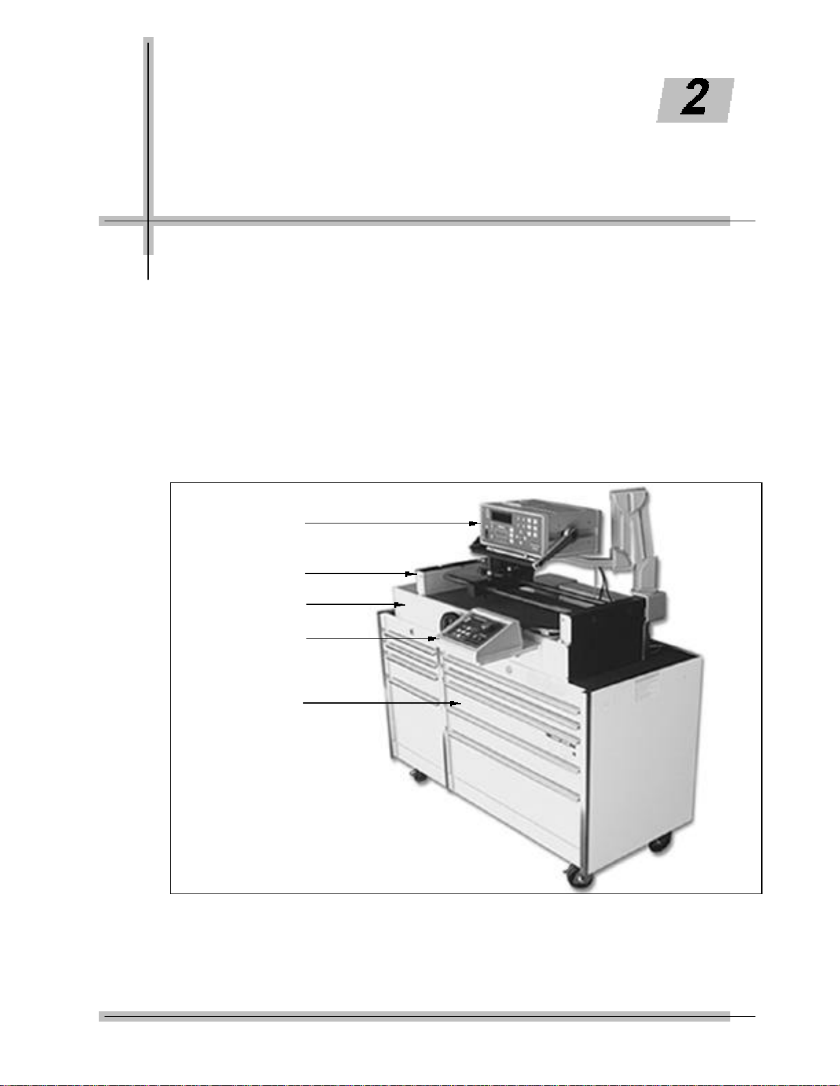
Figure 2-1 Motorized Control Torque Tester/Calibrator
2-1
Functional Description and Specifications
A —Indicator
The 2000-810-01 Indicator monitors and displays the torque
applied.
B —Transducer (Accessory)
The loader accepts all MULTITEST series single transducers
directly. Use a 2000-500-02 adaptor kit to mount the optional
2000-400-02 4-in-1 transducer. For additional information refer
to Appendix A–Accessories.
C —Loader
Use the 2000-800-02 Motorized Loader for testing and
calibrating all torque wrenches, drivers, torque multipliers, nonimpact pneumatic and electric nut runners. It can also be
fixtured for testing and calibrating cable tensiometers and
compression or tension gauges. Loader components are:
• Indicator Stand • Motor
• Safety Shield • Power Amplifier Box
• Hand Crank • Motorized Control Box
• Transducer Mounting
D —Motorized control box.
The MCB controls the motor to generate a torque which is
applied to a wrench while the Torque Tester measures the
resulting torque. When the target torque is reached, the MCB
will stop the motor.
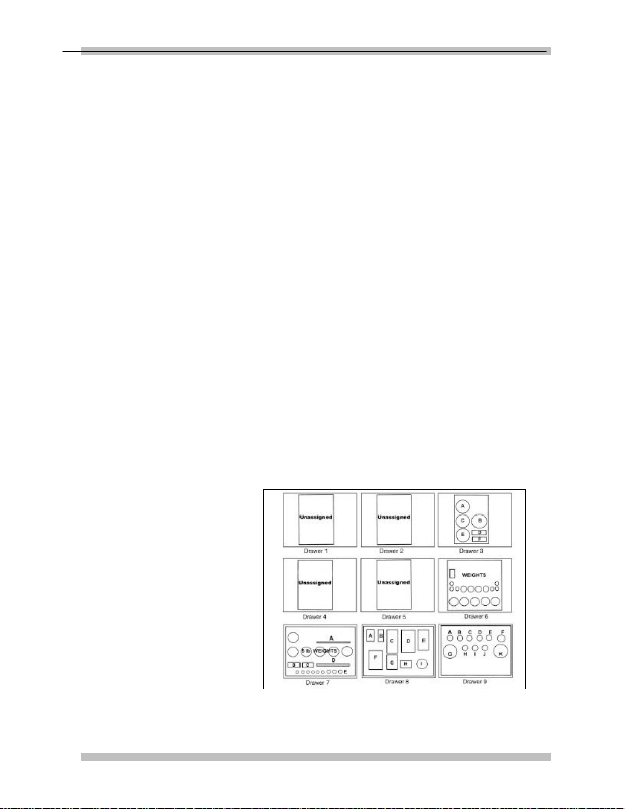
E —Roll Cabinet
The roll cabinet features nine heavy duty drawers with ball
bearing slides, locking wheels and drawer locks. MULTITEST
accessories are stored in the roll cabinet which is fitted with
foam inserts for easy inventory control. The nine drawers are
assigned and arranged as shown in Figure 2-2 .
Figure 2-2: Roll Cabinet Drawer Layout
2-2
Functional Description and Specifications
2000-810-01 Indicator
This section describes the major hardware components of the
MULTITEST Indicator, including:
• Front Panel
• Rear Panel (Input/Output)
• MULTITEST Torque/Force Transducers
NOTE: When used in conjunction with MCB, 2000-810-01 only
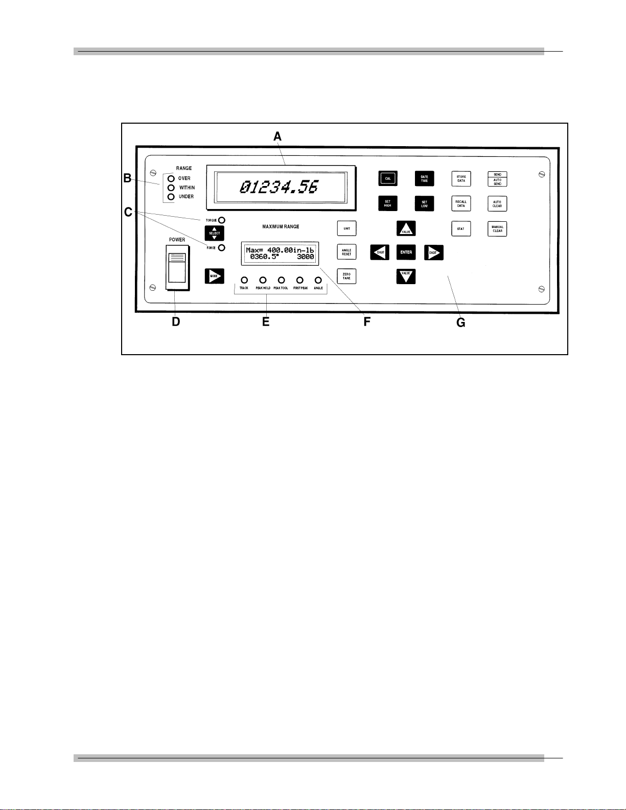
Front Panel
makes torque measurements.
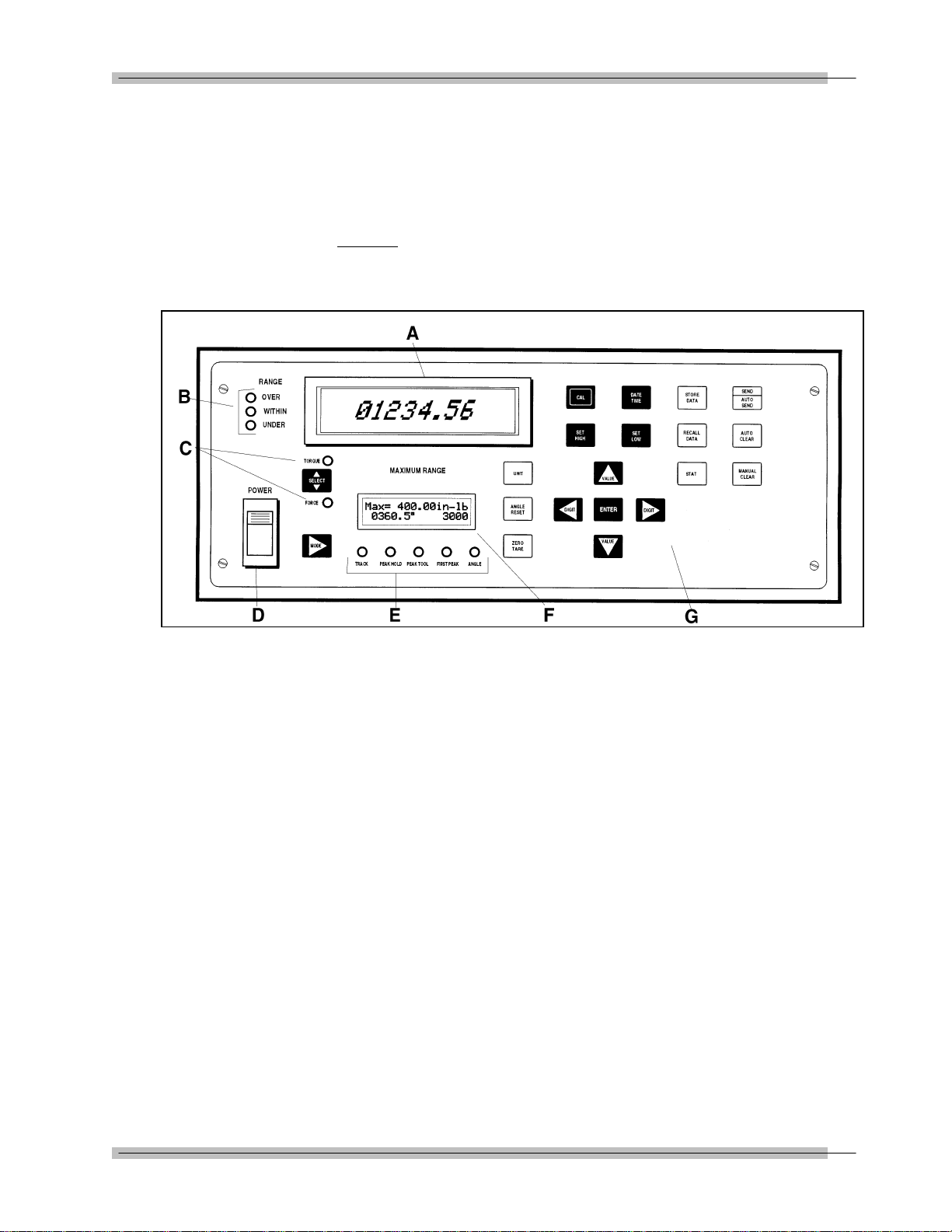
Figure 2-3: 2000-810-01 Front Panel
A —MULTITEST Torque/Force Display
TORQUE or FORCE displays on a bright red alphanumeric
LED, with 0.55" high characters in selected engineering UNITs.
• (+) = Clockwise torque or force
• (-) = Counter clockwise torque or force
B —Range LED Torque or Force Limit Indicators
• Red—OVER (Input exceeds 110% of transducer range)
• Green—WITHIN (Input is within transducer range)
• Yellow—UNDER (Input is below transducer range)
C —Mode Select LEDs
• Red—TORQUE
• Green—FORCE (Manual Loading Only)
D —Power Switch
E —MODE Function LEDs
• Green—TRACK
• Red—PEAK HOLD
• Yellow—POWER TOOL
• Red—FIRST PEAK
• Green—ANGLE
2-3

Functional Description and Specifications
F —Maximum Range Display
Figure 2-4: Maximum Range Display
Two line by 16 character 5x8 dot-matrix LCD display that
shows:
• Maximum transducer range in the selected UNITS of measure
on the upper line,
• Statistical mean of all measurements in memory on the lower
line, left, and
• The number of the present data memory location on the lower
line, right.
This display also is used to indicate:
• ANGLE, in degrees, CW=(+), CCW=(-) of rotation,
• Prompt CALibration mode,
• Programming of angle encoder,
• Printer protocol,
• RECALL display of data list and STATistical analysis, and
• Set up for:
— DATE/TIME clock,
— AUTO/MANUAL CLEAR, STORE and SEND, and
— HIGH and LOW torque/force limits.
2-4

Functional Description and Specifications
G —Front Panel Membrane Function Keys
Toggles between TORQUE and FORCE measurement modes.
Selects TRACK, PEAK HOLD, POWER TOOL, FIRST PEAK
and ANGLE modes.
Selects following units on LCD display:
Torque units in: Nm, dNm, cNm, mkg, cmkg, lb ft, in lb, in oz,
or
Force units in: N, dN, kp, gf,lbf, oz
Manually resets ANGLE display on LCD at any time.
Manually resets ZERO TARE.
Selects LED or LCD digit to right (blinking) for setup and
programming. Shift for printer and angle encoder programming.
Selects LED or LCD digit to left (blinking) for setup and
programming. Shift for printer and angle encoder programming.
Terminates calibration and program modes. Returns to 4-in-1
transducer scan.
Increments selected digit during calibration and program modes.
Scrolls statistical analysis display.
Decrements selected digit during calibration and program
modes. Scrolls statistical analysis display.
NOTE: * Use Torque or Force measurement Mode with hand crank.
* Use Torque measurement mode only with Motorized Control Box.
2-5
Functional Description and Specifications
Opens and terminates calibration mode.
Edits DATE/TIME programming function.
Sets up high torque/force limit preset. Set up angle preset in
torque -angle mode.
Sets up low torque/force limit preset. Set up clamping torque
preset in torque-angle mode.
Stores present measurement to memory.
Recalls memory data to display.
Sends all memory data, statistical analysis and histogram to
printer/port.
Sends data list with or without date-time stamp to computer
printer. Sets up serial protocol function.
Sets up CLEAR, STORE, and SEND modes function.
Manually clears display in PEAK, FIRST PEAK, POWER TOOL
and ANGLE modes. Sets up memory clear options in RECALL
mode.
2-6
Functional Description and Specifications
ABC
DEF
G
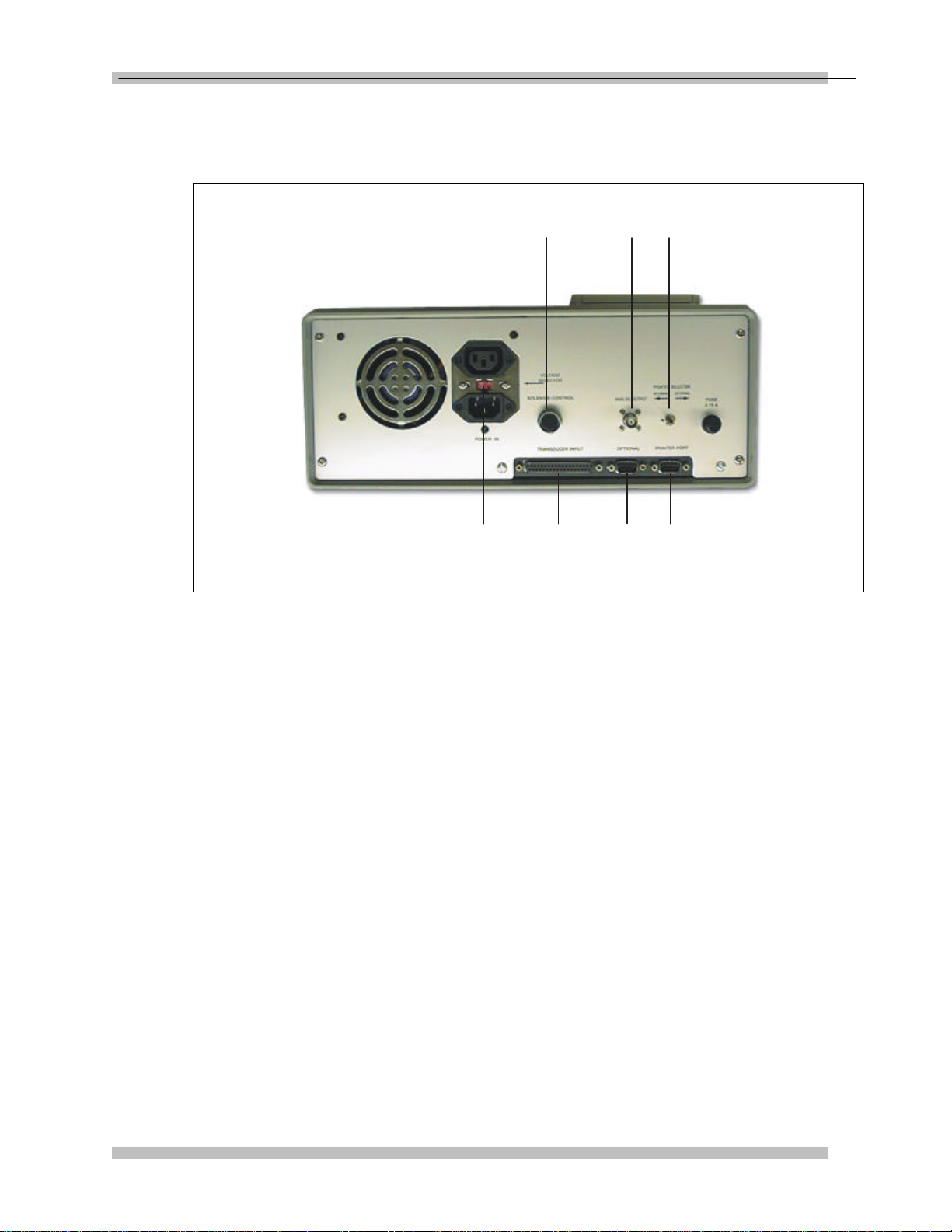
Rear Panel (Input/Output)
The 2000-810-01 Indicator rear panel is shown in Figure 2-5.
Figure 2-5: 2000-810-01 Rear Panel
A —SOLENOID CONTROL (Hirose RM15TRD-12S)
Not used (optional)
B —ANALOG OUTPUT (BNC)
Analog output provides a voltage level output that is directly
proportional to transducer input, from -1.8V (full scale counter
clockwise) to +1.8V (full scale clockwise). Zero offset +/-100
mV. Linearity +/-1% of reading. Maximum load = 5 Ma.
When using the 4-in-1 transducer, zero output
fluctuates until one of the transducers is scan selected
by applying 5% of full scale torque.
C —PRINTER SELECTOR
The INTERNAL/EXTERNAL switch disables the built-in printer.
2-7

Functional Description and Specifications
D —PRINTER PORT (DB-9P)
PIN FUNCTION
2 Receive
3 Transmit
5 Ground
E —OPTIONAL (DB-9P)
PIN FUNCTION
2 Receive
3 Transmit
5 Ground
F —TRANSDUCER INPUT (DB-37S)
PIN FUNCTION
1 not used
2 ground
3 smart chip - bit 2
4 smart chip - bit 0
5 single xducer (-) signal
6 single xducer (+) signal
7 ground
8 4-in-1 xducer (-) signal 2
9 4-in-1 xducer (+) signal 2
10 ground
11 4-in-1 xducer (-) signal 4
12 4-in-1 xducer (+) signal 4
13 4-in-1 xducer LED 2
14 4-in-1 xducer LED 4
15 loader relay CW limit
16 rotary encoder signal A
17 rotary encoder signal B
18 ground
19 bridge excitation (+3V)
20 not used
21 smart chip - bit 3
22 smart chip - bit 1
23 ground
24 ground
25 4-in-1 xducer (-) signal 1
26 4-in-1 xducer (+) signal 1
27 ground
28 4-in-1 xducer (-) signal 3
29 4-in-1 xducer (+) signal 3
30 no transducer
31 4-in-1 xducer LED 1
32 4-in-1 xducer LED 3
33 loader relay CCW limit
34 loader relay common
35 Vcc (+5V@100 ma. max)
36 ground
37 bridge excitation (+3V)
2-8
G —VOLTAGE SELECT
Switch for selecting either 120VAC or 220VAC, 50-60 Hz.

Functional Description and Specifications
MULTITEST Torque/Force Transducers
MULTITEST torque/force transducers provide industry standard
internal square drives. They feature a full bridge strain-gauge
@ 350 Ohms nominal. Full range output is 1500 µE, 9mV,
(3mV/V @ 3.0V excitation).
Torque/force transducers use a built-in EEPROM memory chip
that stores range identification and calibration factors.
Calibration of transducers is accomplished using precision
torque bars and certified weights. For additional information,
refer to Chapter 5—Calibration .
After a transducer is calibrated, it provides +/-0.5% system
accuracy with any MULTITEST Indicator. If the transducer and
indicator are calibrated together, the system accuracy increases
to +/-0.25%.
Transducer Dimensions/Transducer Indicator Torque Range
and Force Range
Torque Force
Stock No. Range Drive Range Height Diameter Weight
2000-5-02 15-200 in oz 1/4" Ext. 3.9 in 3.0 in 1.5 lb
2000-6-02 4-50 in lb 1/4" Ext. 3.9 in 3.0 in 1.5 lb
2000-65-02 15-150 in lb 1/4" Ext. 3.9 in 3.0 in 1.5 lb
2000-7-02 30-400 in lb 3/8" Ext. 33.3 lbf 4.1 in 3.0 in 3.0 lb
2000-8-02 80-1000 in lb 3/8" Ext. 83.3 lbf 4.1 in 3.0 in 3 lb
2000-10-02 10-125 ft lb 1/2" Ext. 125 lbf 4.25 in 4.0 in 5 lb
2000-11-02 20-250 ft lb 1/2" Ext. 250 lbf 4.25 in 4.0 in 5 lb
2000-12-02 60-600 ft lb 3/4" Ext. 600 lbf 4.25 in 4.0 in 5 lb
2000-13-02 100-1000 ft lb 1" Internal 1000 lbf 5.5 in 6.1 in 24 lb
2000-14-02 200-2000 ft lb 1" Internal 2000 lbf 5.5 in 6.1 in 24 lb
2000-400-02 4-50 in lb 1/4" Ext. H2.6-W5.0-L10.0 in 6 lb
(4-in-1) 30-400 in lb 3/8" Ext.
80-1000 in lb 3/8" Ext.
20-250 ft lb 1/2" Ext.
Calibration also results in a specified display resolution on the
MULTITEST Indicator. Display resolution is dependent on the
type of transducer being used. The following table shows
display resolutions for the specified transducer with the force
arm.
2-9

Functional Description and Specifications
Display Resolution for Transducers in Force Mode
N dN lbf ozf kp gf
2000-7-02 03 .3 .007 .1 .003 3
2000-8-02 .08 .8 .02 .3 .008 8
2000-10-02 .1 1 .02 .4 .01 10
2000-11-02 .2 2 .05 .8 .02 n/a
2000-12-02 .5 5 .12 2 .05 n/a
2000-13-02 .9 9 .2 3 .1 n/a
2000-14-02 1.8 18 .4 6 .2 n/a
Display Resolution for Transducers in Torque Mode
mkg cmkg ft lb in lb in oz Nm dNm cNm
2000-5-02 .00003 .003 .0002 .002 .04 .0003 .003 .03
2000-6-02 .0001 .01 .0008 .01 .2 .001 .03 .3
2000-65-02 .0003 .03 .002 .03 .5 .003 .03 .3
2000-7-02 .001 .1 .006 .08 1.2 .009 .09 .9
2000-8-02 .002 .2 .016 .2 3.2 .02 .2 2
2000-10-02 .004 .4 .03 .3 5 .03 .3 3
2000-11-02 .007 .7 .05 .6 10 .07 .7 7
2000-12-02 .016 1.6 .12 1.4 n/a .16 1.6 16
2000-13-02 .03 3 .2 3 n/a .3 2.7 n/a
2000-14-02 .05 5 .4 5 n/a .5 5 n/a
2000-400-02 .0001 .01 .0008 .01 .2 .001 .03 .3
(4-in-1) .001 .1 .006 .08 1.2 .009 .09 .9
.002 .2 .016 .2 3.2 .02 .2 2
.007 .7 .05 .6 10 .07 .7 7
2-10
MULTITEST torque/force transducers can withstand an overload
of 110% of full range. The 2000-810-01 Indicator alarms,
(audible beep and display "OVER" red LED) at 110% of rated
capacity.
To protect the tool under test or serve as a fastener installation,
torque preset alert, the 2000-810-01 produces a constant
audible tone when the input torque/force exceeds the SET LOW
limit. It then produces a pulsating tone when the input
torque/force exceeds the SET HIGH limit.
2000-810-01 ignores inputs less than 0.1% of full range in
TRACK mode, 2% in PEAK HOLD mode, 7% in FIRST PEAK
and POWER TOOL modes. With the 4-in-1 transducer, 2000810-01 ignores inputs less than 2% of full range after scan
select.

Functional Description and Specifications
Specifications
MOTORIZED CONTROL LOADER System
System Accuracy
±0.25% of reading @ 25°C
(Indicator and transducer calibrated together)
MULTITEST Transducers used with, but not calibrated
to, another MULTITEST Indicator provide a system
accuracy of ±0.5% of reading @ 25°C.
Temperature Drift
+0.03%/°C (+0.017%/°F)
Angle Precision
Bi-directional rotary encoder pulses/revolution X4
2000-810-01 Indicator
Display Accuracy
±0.05% of reading @ 25°C
Temperature
Operating Temperature
10 to 32°C (50 to 90°F)
Storage
-20 to 50°C (-2 to 122°F)
Humidity
Up to 90%, Non-condensing
Temperature Drift
+0.011%/°C, (+0.006%/°F)
Dimensions
Width 16.5“
Height 6.25"
Depth* 14.5"
*Includes handle, feet, printer and connectors
Weight
13.5 lbs
Power Supply
UL approved, 120VAC/220VAC, 50-60 Hz
Amperage, 3.15 amps
2-11

Functional Description and Specifications
Data Storage/Recall w/Date Time Stamp
3,000 measurements
Statistical Analysis
Max, Min, Range, Mean, Sigma N, Sigma, Cp, Cpk
%Error, -NoGo, +NoGo.
Histogram: Lower Set Limit, Upper Set Limit, 10 Divisions
Printer/Computer Serial Output Port
Serial Communications
RS-232 (true)
300—19.2K Baud
8 data bits
1 stop bit
no parity
Computer Serial COM Port
RS-232 (True)
300—19.2K Baud
NOTE OPTIONAL: This port will communicate with the Motorized
Control Box at 19.2K Baud.
Analog Output
+(CW)/-(CCW) 1.8V at transducer full range linearity
±1% of reading
Loader Control Relays
Two, normally open, Form A, rated 12VDC @ 1/2A close
contact at 110% CW or CCW of torque/force transducer range.
For additional information refer to Transducer and
System specifications.
Display Capacity
(16 bit A/D), 8 digits, ±32,000 counts
Units of Measurement
Torque
ft lb, in lb, in oz, Nm, dNm, cNm, mkg and cmkg
Force
lbf, ozf, N, dN, kp, and gf
Angle
degrees
2-12
Torque/Force Resolution
Refer to transducer-indicator range and display resolution tables
in Functional Description of this chapter.
Angle Resolution
Bi-directional, X4 quadrature logic

Functional Description and Specificatons
Torque/Force Transducers
Accuracy
±0.2% of reading @ 25°C, within specified range, when used as
prescribed with the 2000-800-02 Loader.
Range and Resolution
Refer to transducer-indicator range and display resolution tables
in Functional Description of this chapter.
Temperature
Operating Temperature
10 to 32°C (50 to 90°F)
Storage
-20 to 50°C (-2 to 122°F)
Humidity
Up to 90% non-condensing
Temperature Drift
+0.02%/°C (+.011%/°F)
2000-800-02 Motor Loader Specifications
Input Torque (Hand Crank when E-Stop pushed down)
10 ft lb maximum .
Output Torque
2000 ft lb ±20 degrees rotation maximum
Power Requirements (Motor and Control Box)
115VAC ±10%, @ 60 Hz
230VAC ±10%, @ 50 Hz (Optional Step-down transfromer)
Physical Dimensions
Width
45"
Height
50"
Depth
24"
Weight (including 2000-100-02 roll cab)
1500 lbs
Optional Calibration Fixturing (load bars and weights)
±0.05% accuracy
2-13
Setup and
Programming
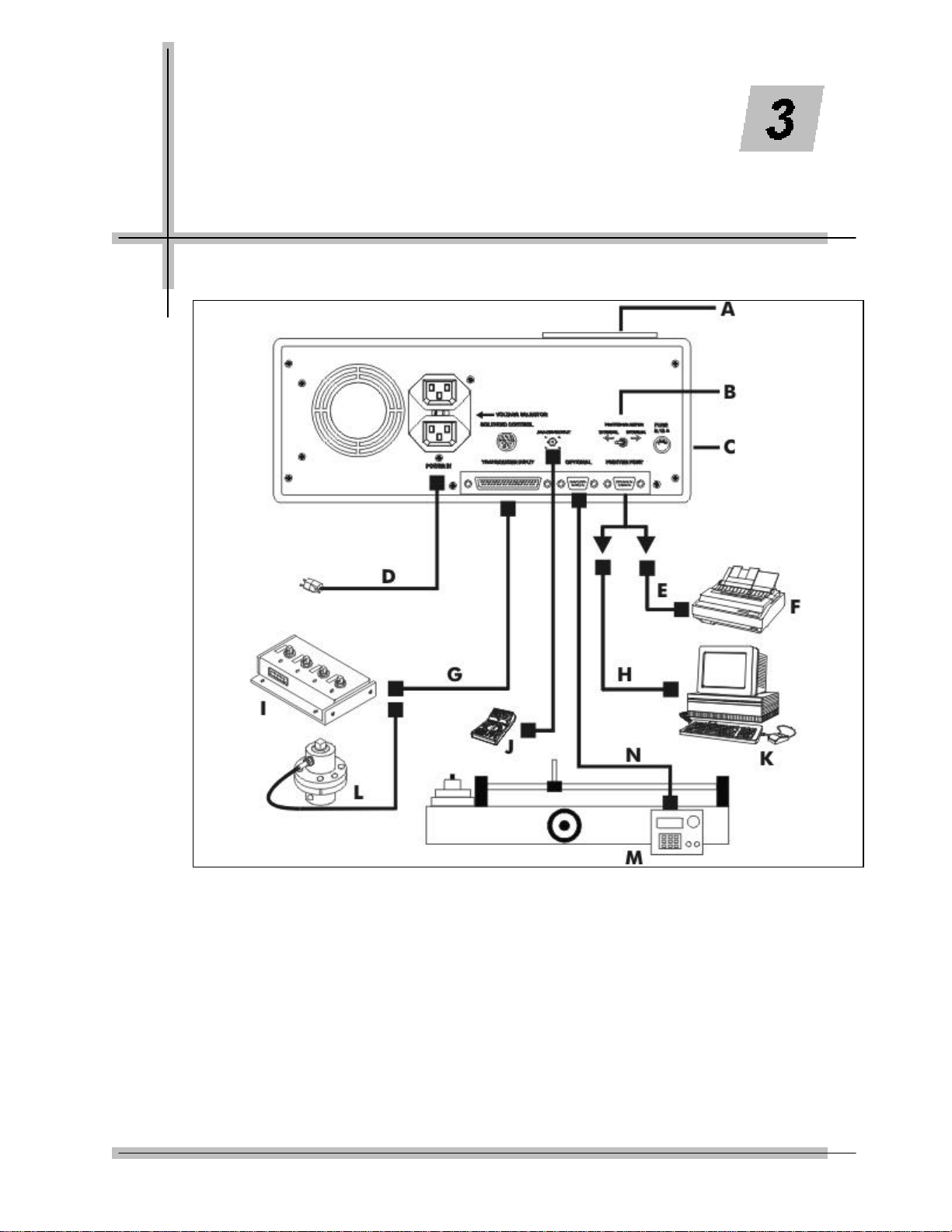
Motorized Control Loader System Setup
Figure 3-1: Motorized Control Torque Tester/Calibrator/Loader Setup
A – Internal printer
B – Internal/External printer selector switch
C – 2000-810-01 Indicator rear panel
D – Power cables (110/220 VAC)
E – Printer cable
F – External printer
G – Transducer cable
H – Personal computer cable
I – Smart 4-in-1 transducer
J – Analog device
K – Personal computer
L – Smart single transducer
M – Motorized Loader
N – Indicator to Motor Control Box cable
3-1

Setup and Programming
Setting Up the Motorized Control Loader System
1. Position the roll cabinet on a level floor and lock the
wheels.
2. Mount the indicator stand, part number 2000-111-0, to
the Loader.
3. Mount the 2000-810-01 Indicator to the stand.
4. Connect the cables between the Indicator, Motorized
Control Box and Power Amplifier Box.
(Refer to chapter 6)
5. Install the appropriate MULTITEST transducer to the
Loader drive.
6. Install two (2) quick release pins, part number 2000-195-
12.
7. Connect the transducer cable, part number 2000-900120, between the Indicator and transducer.
8. Select the appropriate AC voltage input at the rear of the
Indicator. Connect the AC power cables to the Indicator
and the Power Amplifer Box. For additional information
refer to Chapter 6—Loader Rear Panel Controls.
9. Install the safety shield to the front of the Loader.
10. Install the reaction pins into the reaction slide on the
Loader.
For testing procedures refer to Chapter 4—Using
the Torque Tester.
Various fixtures, cables and adaptors are available for testing
the most common compression or tension gauges. Ask your
CDI sales representative for assistance.
3-2
2000-810-01 Indicator Controls
Refer to the illustration below when performing the power-up
and programming procedures.
Setup and Programming
Figure 3-2: Indicator Controls
A – 2000-810-01 Torque/Force Display
B – Range LED Torque or Force Limit Indicators
C – Load Select LEDs
D – Power Switch
E – MODE Function LEDs
F – Maximum Range Display
G – Front Panel Membrane Function Keys
3-3
 Loading...