

Page 1
Page 2

TABLE OF CONTENTS
Safety Information I
Introduction 1-1
Functional Description and Specifications 2-1
Functional Descriptions 2-1
SURETEST Torque Calibration System 2-1
Roll cabinet 2-2
Front Panel 2-3
Rear Panel (Input/Output) 2-9
Torque Transducers 2-11
Specifications 2-12
SURETEST Torque Calibration System 2-12
Manual loader specifications 2-14
Setup and Programming 3-1
SURETEST Torque Calibration System Setup 3-1
Setting Up the Suretest System 3-2
Suretest Controls 3-3
Powering the Equipment 3-3
4-in-1 Transducer Select 3-4
Programming Setup 3-5
Setting up Date and Time 3-5
Setting Up High and Low Limits Alert 3-5
Programming AUTO CLEAR 3-6
DATA LIST Memory 3-7
Setting Up Printer/PC Ports 3-8
Selecting Printer/PC Ports 3-8
Setting Up Serial Communications 3-8
Torque Calibration System Setup 4-1
Testing Torque Wrenches and Drivers 4-1
Selecting a Transducer 4-1
Installing a Transducer 4-1
Dial and Bending Beam Torque Wrenches and Screwdrivers 4-2
Adjustable or Preset “Click” Wrenches and Screwdrivers 4-3
Testing Power Tools 4-4
Non-Impact Tools 4-4
Displaying Statistical Analysis 4-7
Displaying Statistical Analysis on LCD 4-7
Printing Statistical Analysis 4-8
Displaying or Downloading Data List 4-10
Displaying Data List on LCD 4-10
Downloading Data List to Printer 4-10
How to Use Analog Output (Rear Panel BNC Connector) 4-11
Calibration 5-1
Mounting Details 5-1
Quick Check 5-4
Torque Transducer Calibration 5-7
TABLE OF CONTENTS 1
Page 3

Suretest Indicator Torque Calibration 5-11
Gravitational Effects 5-14
Correction Factors on Test Weights 5-14
Gravitational Charts 5-14
2000-600-02 Manual Loader 6-1
Application 6-1
Torque Tester/Calibrator 6-2
2000-600-02 Manual Loader 6-3
Loader Rear Panel Controls 6-5
Ball Handle Adaptor 6-6
4-in-1 Transducer (Accessory) 6-7
Extension Arm (Accessory) 6-8
Types of Loader Testing 6-9
Torque Driver Testing 6-9
Torque Multiplier Testing 6-9
Accessories A-1
SURETEST System Components and Inventory Control A-2
Optional Transducers and Accessories A-3
Calibration Accessories A-5
TABLE OF CONTENTS 2
Page 4

Using this Manual
This manual contains instructions for use and setup of the Suretest Torque Calibration
System. A table of contents and a table of illustrations are provided to make this manual
easy to use.
Some of the information shown in text or illustrations is obtained using optional
equipment.
Conventions
This section contains a list of conventions used in text.
Chapter References
Additional information in text is referenced by chapter number and section name.
Example:
For testing procedures refer to Chapter 4—Using the SURETEST System.
Equipment Damage
The possibility of damage to vehicle or equipment is introduced by a signal word
indicating this condition.
Example:
IMPORTANT
The connector on single transducer cables contains the EEPROM calibration memory
chip. Never attempt to remove the connector from the transducer. It is installed with a
permanent adhesive.
Safety Messages
Safety messages are provided to help prevent personal injury and equipment
damage. All safety messages are introduced by a signal word indicating the
hazard level. The types of safety messages are: Danger, Warning and Caution.
TABLE OF CONTENTS 3
Page 5

DANGER
Indicates an imminently hazardous situation which, if not avoided, will
result in death or serious injury to the operator or to bystanders.
WARNING
Indicates a potential hazard which, if not avoided, could result in death or
serious injury to the operator or to bystanders.
CAUTION
Indicates a potential hazard which, if not avoided, may result in minor or
moderate injury to the operator or to bystanders.
The three-part message panel, used with safety messages, uses three different type styles
to further define the potential hazard:
• Normal type states the hazard,
• Bold type states how to avoid the hazard, and Warning.
• Italic type states the possible consequences of not avoiding the hazard.
Some safety messages contain visual symbols with signal words.
Example:
WARNING
Flying particles can discharge when applying torque.
• Users and bystanders must wear safety goggles.
• Always wear safety goggles when applying torque.
Flying particles can cause injury.
4
Page 6

Safety Information
Important Safety Instructions
This manual contains important safety and operating instructions for CDI SURETEST
Torque calibration system. Refer to the information in this manual often for safe
operation.
Read All Instructions
Read, understand and follow all safety messages and instructions in this manual and on
the test equipment. Safety messages in this section of the manual contain a signal word, a
three-part message.
The signal word indicates the level of hazard in a situation:
• Danger indicates an imminently hazardous situation which, if not avoided, will result in
death or serious injury to the operator or bystanders.
• Warning indicates a potentially hazardous situation which, if not avoided, could result
in death or serious injury to the operator or bystanders.
• Caution indicates a potentially hazardous situation which, if not avoided, may result in
moderate or minor injury to the operator or bystanders.
The three-part message uses three different type styles to further define the potential
hazard.
• Normal type states the hazard.
• Bold type states how to avoid the hazard.
• Italic type states the possible consequences of not avoiding the hazard.
SAVE THESE INSTRUCTIONS
WARNING
Risk of electric shock and fire.
• For indoor use only. Do not expose charger to rain or snow. Do not use in damp
locations.
• Replace defective cord immediately. Return to qualified service center for replacement.
Electric shock or fire can cause injury.
WARNING
Flying particles can discharge when applying torque.
• Users and bystanders must wear safety goggles.
• Always wear safety goggles when applying torque.
• Do not use this equipment with the power off. Always turn on the indicator and loader
so the torque and load values are indicated on the display. The safety relays only work
when the power is on. Flying particles can cause injury.
5
Page 7

WARNING
Risk of entanglement.
• When starting power tools, check for obstacles near your hand and anticipate the
reaction force by gripping the tool firmly.
• Do not wear loose clothing and jewelry while operating a power tool. Loose clothes
and jewelry can be caught in moving parts.
• Keep body parts away from rotating parts.
• Wear a protective hair covering to contain long hair and prevent contact with moving
parts.
• Do not overreach. Keep proper footing and balance at all times.
Entanglement can cause injury.
WARNING
Improper use can cause breakage.
• Read instructions before operating.
• Follow manufacturer’s instructions, safety precautions, and specifications when
operating tools. Broken equipment can cause injury.
WARNING
• Make sure all components, including, adaptors, extensions, drivers and sockets are rated
to match or exceed the torque or load being applied.
• Be sure the capacity of the SURETEST system matches or exceeds each application
before performing a procedure.
• Do not use the SURETEST system if it makes unusual noises, has loose parts, or shows
any other sign of damage. Have repairs performed at an Authorized Service Center
before use.
• Do not use chipped, cracked, or damaged sockets and accessories.
• Do not remove any labels. Replace any damaged label.
• Follow good, professional tool practices:
** Pull on a wrench handle ** do not push ** and adjust stance to prevent a possible
fall.
** Do not use extensions, such as a pipe, on a wrench handle.
• When using ratchets, make sure the direction lever is fully engaged in the correct
position.
• Never attempt to test an impact tool on this instrument.
• Always position the 40" arm over the front of the stand as shown. Never extend the test
arm behind the stand. The stand will tip over when weights are applied.
• Always be alert to the potential for personal injury that may be caused by excessive
torque applications, careless handling of heavy weights, and out-of-balance or unsafe
weight distribution.
6
Page 8

PRODUCT DESCRIPTION
CDI-SURETEST MODEL 5000-ST
The SURETEST is a laboratory grade instrument that provides
TORQUE measurements. Although designed as an independent
laboratory equipment, it can also be used in an integrated environment as
the principal component of a Torque Calibration System. The
SURETEST features versatile data acquisition capabilities including
measurement storage, retrieval, statistical analysis and automatic
downloading to an external printer/computer. A remote computer COM
port is available for PC interfacing.
Used with precision torque transducers, the SURETEST provides high
speed monitoring of static or dynamic torque inputs. Torque/force
transducers, purchased separately, are available in ranges from 15-200
in- oz, to 200-2000 ft-lb, and provide system readings with an accuracy
of +/- 0.25% of indicated value, or better. A special memory chip is
built into each torque/force transducer that identifies its range and
maintains its calibration between any other SURETEST with an
accuracy of +/- 0.5%. The SURETEST and its transducers may be
calibrated by using accessory precision bars and certified weights.
All readout of torque in ft-lb, in-lb, in-oz, Nm, dNm, cNm, mkg as well
as calibration, statistical analysis and set-up functions are reported on a
versatile 1.5” x 5.5” graphic dot matrix Liquid Crystal Display (LCD).
Set-up and calibration programming is entered using easy-to-use front
panel membrane keys. The number of keys is kept to a minimum. In
addition, concise menus and graphic symbols are used to guide the user
through all set-ups and operations. HIGH and LOW torque limits are
adjustable to give an audible alert. The user selects TRACK mode to
display torque values as they are applied, PEAK HOLD or POWER
TOOL modes to display the highest torque value applied, or FIRST
PEAK mode which captures the torque output at the “click” of a set-able
wrench or driver. CLEAR, STORE and SEND functions can be set up
for automatic or manual operation.
The SURETEST stores and recalls up to 3000 torque readings and does
statistical analysis on them for downloading to printer or computer. The
statistical report (print out) includes a simple histogram for process
monitoring. True RS-232 serial printer and separate RS-232 computer
COM ports are at the back of the unit
7
Page 9

CHAPTER 1
Introduction
The SURETEST is a laboratory grade instrument that provides
TORQUE measurements. Although designed as an independent digital
indicator, it can also be used in an integrated environment as the
principal component of a Torque Calibration System. The SURETEST
features versatile data acquisition capabilities including measurement
storage, retrieval, statistical analysis and automatic downloading to an
external printer/computer. A remote computer COM port is available for
PC interfacing.
Used with precision torque transducers, the SURETEST provides high
speed monitoring of static or dynamic torque inputs. Torque transducers,
purchased separately, are available in ranges from 15-200 in- oz, to 2002000 ft-lb, and provide system readings with an accuracy of ± 0.25% of
indicated value, or better. A special memory chip is built into each
torque transducer that identifies its range and maintains its calibration
between any other SURETEST with an accuracy of ± 0.5%. The
SURETEST and its transducers may be calibrated by using accessory
precision bars and certified weights.
All readout of torque in ft-lb, in-lb, in-oz, Nm, dNm, cNm, mkg as well
as calibration, statistical analysis and set-up functions are reported on a
versatile 1.5” x 5.5” graphic dot matrix Liquid Crystal Display (LCD).
Set-up and calibration programming is entered using easy-to-use front
panel membrane keys. The number of keys is kept to a minimum. In
addition, concise menus and graphic symbols are used to guide the user
through all set-ups and operations. HIGH and LOW torque limits are
adjustable to give an audible alert. The user selects TRACK mode to
display torque values as they are applied, PEAK HOLD or POWER
TOOL modes to display the highest torque value applied, or FIRST
PEAK mode which captures the torque output at the “click” of a set-able
wrench or driver. CLEAR, STORE and SEND functions can be set up
for automatic or manual operation.
The SURETEST stores and recalls up to 3000 torque readings and does
statistical analysis on them for downloading to printer or computer. The
statistical report (print out) includes a simple histogram for process
monitoring. True RS-232 serial printer and separate RS-232 computer
COM ports are at the back of the unit.
Page 10

FUNCTIONAL DESCRIPTIONS AND SPECIFICATIONS CHAPTER 2
The SURETEST operates directly from any AC power line between
120VAC to 220 VAC, 50–60 Hz without the need for switch selection. A
hard-wired lithium battery keeps the internal memory and date-time
clock operating for up to 10 years. The real time clock is fully year 2000
compliant.
The information in this manual is general. Operational features, procedures and
specifications may change without notice. CDI makes no claims as to the suitability of
this information for diverse user applications.
Page 11
FUNCTIONAL DESCRIPTIONS AND SPECIFICATIONS CHAPTER 2
CHAPTER 2
Functional Descriptions and Specifications
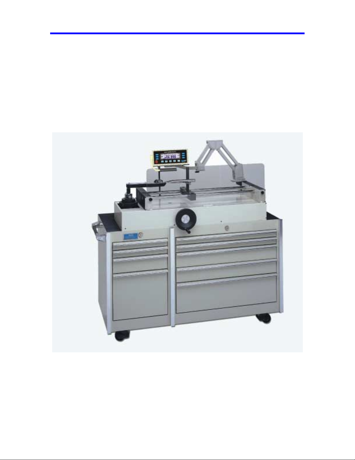
The SURETEST is CDI’s next generation Torque Measurement System. It provides
exceptional accuracy and ease of use. It is packaged in a compact, sturdy and attractive
housing unit which requires little room on a laboratory bench. The SURETEST is
typically used in conjunction with a Transducer and a Mechanical Loader.
Fig 2-1
Base Unit
The SURETEST monitors and displays the torque applied.
Transducer (Accessory)
Page 12

FUNCTIONAL DESCRIPTIONS AND SPECIFICATIONS CHAPTER 2
The loader accepts all SURETEST series single transducers directly. Use a 2000-500-02
adapter kit to mount the optional 2000-400-02 4-in-1 transducer. For additional
information refer to Appendix A–Accessories.
Loader
Use the 2000-600-02 Manual Loader for testing and calibrating all torque wrenches,
drivers, torque multipliers, non-impact pneumatic and electric nut runners. Loader
components are:
• Stand For Base Unit
• Safety Shield
• Hand Crank
• Transducer Mounting
Roll Cabinet
The roll cabinet features nine heavy duty drawers with ball bearing slides, locking wheels
and drawer locks. SURETEST accessories are stored in the roll cabinet which is fitted
with foam inserts for easy inventory control. The nine drawers are assigned and arranged
as shown in figure A-1 of Appendix A.
SURETEST Base Unit
This section describes the major hardware components of the SURETEST Base Unit,
including:
• Front Panel
• Rear Panel (Input/Output)
• SURETEST Torque Transducers.
Page 13
FUNCTIONAL DESCRIPTIONS AND SPECIFICATIONS CHAPTER 2
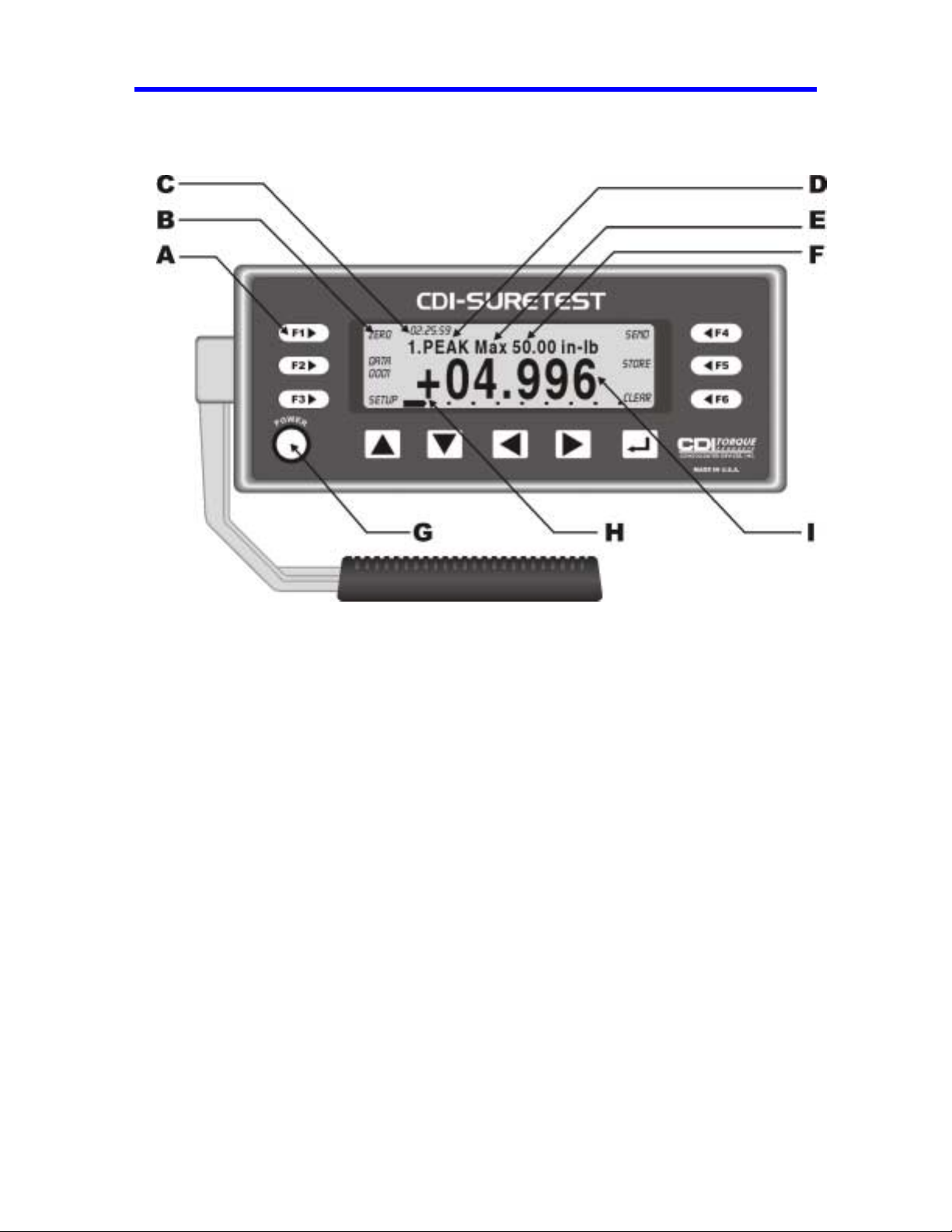
FRONT PANEL
Figure 2-3: SURETEST Front Panel
A- Membrane Function ( F1, F2, F3, F4, F5, F6 ),
And Cursor/Selection (Up, Down, Left, Right and Enter ) Keys.
B- Soft Key Menu: Zero, # Data Stored, Setup, Send, Store, Clear, Escape, Format.
C- Real Time Clock. HH:MM:SS
D- Modes: Track, Peak Hold, First Peak and Power tools.
E- Maximum Range of Transducer.
F- Engineering Units : Nm, dNm, Ncm, mkg, cmkg, ft.lb, in.lb, in.oz
G- Power: On/Off
H- Scroll Bar Each dot represents 10% of Full scale.
I- Torque Reading: Full 5-digit readi ng Plus Sign (for dir ection)
Page 14

FUNCTIONAL DESCRIPTIONS AND SPECIFICATIONS CHAPTER 2
SURETEST DISPLAY
A 240 x 64 Full-featured Graphic LCD is used to provide versatile and clear displays of system
menus as well as measurements. Characters and symbols are displayed in different fonts:
• Maximum transducer range in the selected UNITS of measure.
• Statistical mean of all measurements in memory.
• The number of the present data memory location.
Front Panel Membrane Cursor and Function Keys
The SURETEST is supported by a powerful Graphic User Interface (GUI). Set up, Command, or
Control is done by selecting the appropriate Action Item on one of the provided Menus. Front
Panel Membra ne Cursor and Functio ns keys are defined to gui de the User in selecting an Action
Item.
There are 6 function (soft) keys:
the LCD.
To select an Action Item, the User simply presses a Function Key (F1-F6) to get to a Menu, uses
a Cursor Key to move to the Item, then hits ‘ENTER’ .
In addition to the
The GUI also provides P rompts to further a ssi st the user in navigating the Menus.
‘ENTER’ key, there are 4 Cursor Keys : UP , DOWN , LEFT , RIGHT .
F1 through F6. Their respective uses are clearly indicated on
Power Up Sequence
Upon power up, the SURETEST automatically performs Self-tests and displays the results. Any
detected non-functional hardware will be reported on the LCD. If a 4-in-1 transducer is
connected, the SURETEST performs ZEROTARE, then displays the following default menu
while continuously checking for any activity from an input transducer :
The user can either press F1 to display previously collected data (if any) or enter Setup Mode.
Any detected torque measurement will cause the SURETEST to enter Measurements mode where
the following menu is displayed:
Page 15
FUNCTIONAL DESCRIPTIONS AND SPECIFICATIONS CHAPTER 2
The SURETEST always returns to the default menu from the measurements mode in the event there is no
selection / input by the User. This serves as a reminder for more (input) measurements.
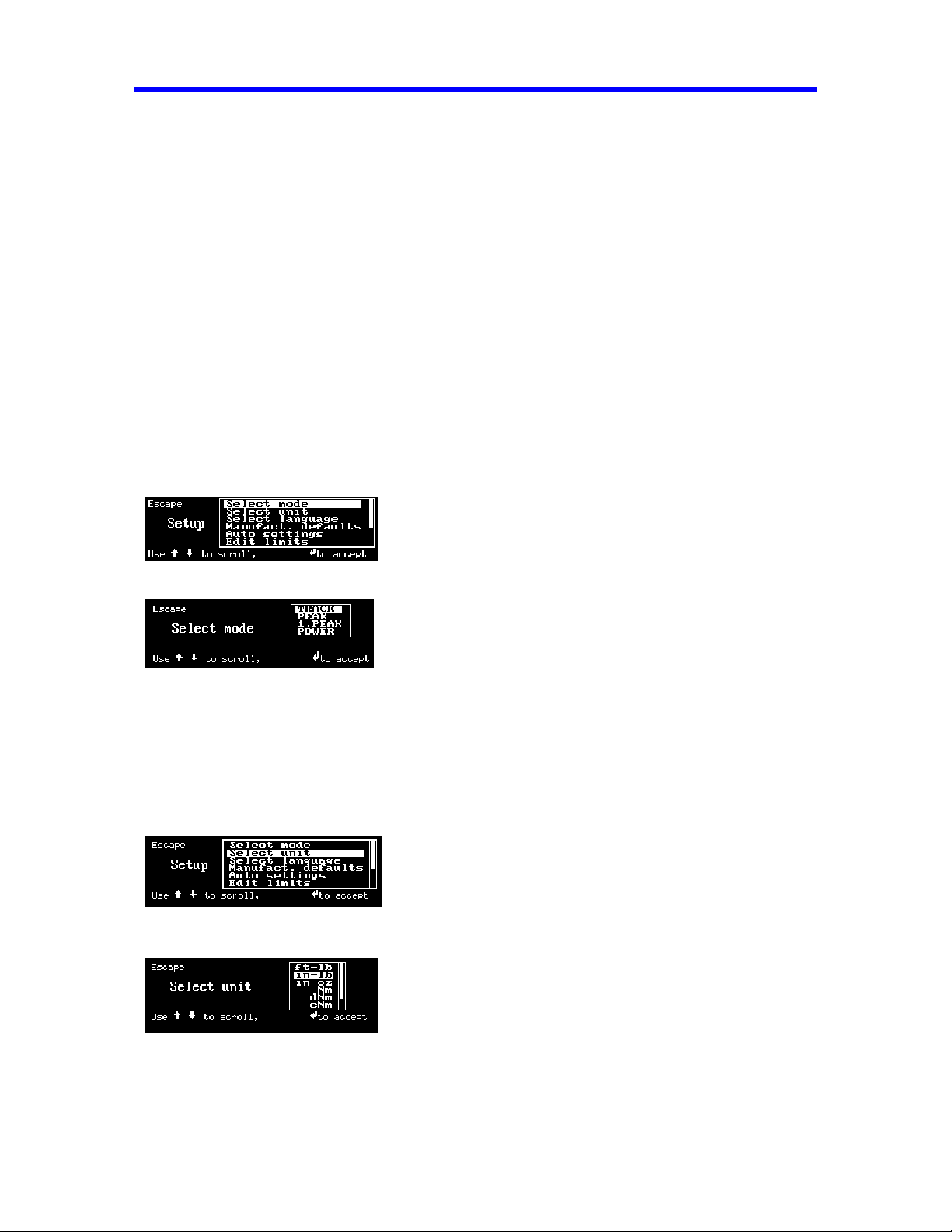
Setup Mode
The following Selections are available:
1. SELECT MODE
2. SELECT UNIT
3. SELECT LANGUAGE
4. MANUFACTURER’S DEFAULTS
5. AUTO SETTINGS
6. EDIT LIMITS
7. CLOCK ADJUST
8. CALIBRATION
9. EDIT P ARAMETERS
10. CDI INTERNAL
11. ABOUT
1. Select Mode
Selects either TRACK, PEAK HOLD, FIRST PEAK, or POWER mode.
• TRACK : In this mode, the SURETEST continually makes Torque Me asurements.
• PEAK : The SURETEST makes Torque Measurement at the Highest Peak.
• 1.PEAK : The SURETEST makes Torque Measurement at the First Peak.
• POWER : The SURETEST makes Torque Measurement at the Highest Peak at a faster rate.
2. Select Unit
Selects the following Torque units on LCD display:
Nm, dNm, cNm, mkg, ft-lb, in-lb, in-oz .
Page 16
FUNCTIONAL DESCRIPTIONS AND SPECIFICATIONS CHAPTER 2
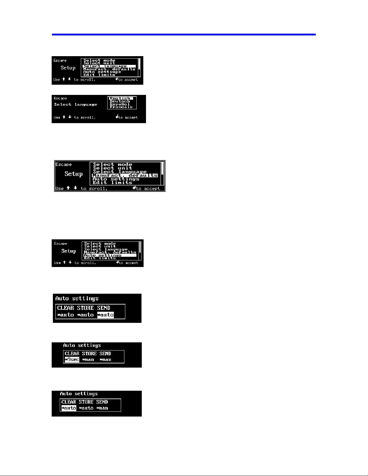
3. Select Language
Selects either English, German (Deutsch), French (Francais), Spanish (Espanol),
or Portugue se (Portugues) .
4. Manufacturer’s Defaults:
A warning message is first displayed. Upon confirmation by the User, the Default Settings
will be loaded into the SURETEST.
5. Auto Settings
Sets up CLEAR, STORE, and SEND functions. There are 2 options: Automatic or Manual.
Selection: Automatic Clear, Automatic Store and Automatic Send data out (to RS-232 port).
Selection: Delay 9 seconds then clear the Display, Manual Store and Manual Send.
Selection: Automatic Clear, Automatic Store and Manual Send.
Page 17
FUNCTIONAL DESCRIPTIONS AND SPECIFICATIONS CHAPTER 2
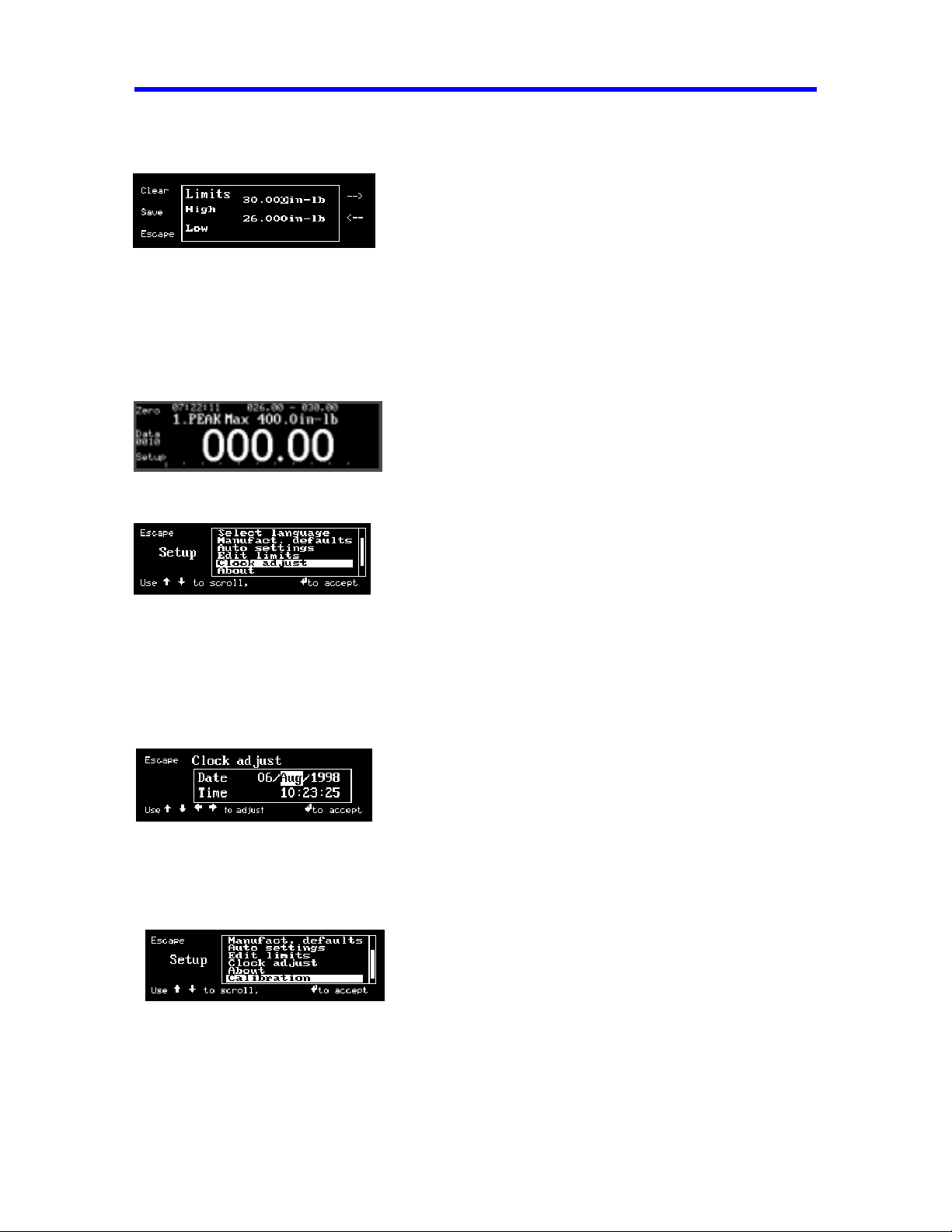
6. Edit Limits
Sets up high torque limit preset. (->) to go Down 1 line.
Sets up low torque limit preset. (<-) to go Up 1 line.
Use Up or Down cursor key to increment or decrement the respective value.
Use Left or Right cursor key to select digit.
Press ‘Save’ to activate the change. Press ‘Clear” to Clear All Limit set-up.
Press ‘Escape’ to Exit. Last setup is retained.
7. Clock Adjust
Edits DATE/TIME programming function.
To adjust the Clock, use LEFT or RIGHT cursor key to get to Day, Month, Year, Hour,
Minute, or Second field. Then use UP or DOWN cursor key to increment or decrement
the respective value.
Press and hold the cursor key to change the value quickly.
Press ‘ENTER’ to activate the change.
8. Calibration
This enables the User to perform calibration of the SURETEST. The procedures for both the
single and 4-in-1 transducers are in Chapter 5.
Page 18
FUNCTIONAL DESCRIPTIONS AND SPECIFICATIONS CHAPTER 2
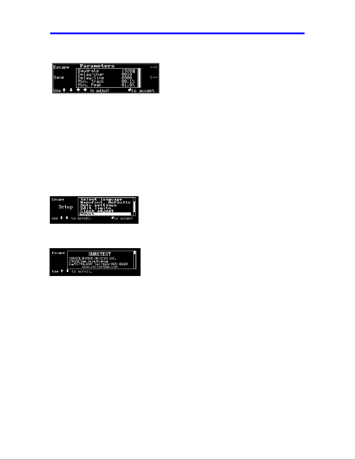
9. EDIT PARAMETERS
Sets up serial protocol function.
Sets delay (in ms) per character upon printing.
Sets delay (in ms ) per Linefeed.
Minimum block-out with zero at 0.1% F.S. in Tracking Mode.
Minimum block-out with zero at 1.0% F.S. in Peak-Hold Mode.
10. CDI INTERNAL
For Manufacture r’s use only.
11. About
This provides relevant information regarding the CDI company, the software version, and the
serial number of the SURETEST device.
12. Other Features:
Provides manual ZERO TARE.
Stores present measurement to memory.
Recalls memory data to display.
Sends all memory data, statistical analysis and histogram to printer port.
Sends data list with or without date-time stamp to computer / printer.
Manually clears display in PEAK, FIRST PEAK, POWER TOOL modes.
Sets up memory clear options in RECALL mode.
Page 19
FUNCTIONAL DESCRIPTIONS AND SPECIFICATIONS CHAPTER 2
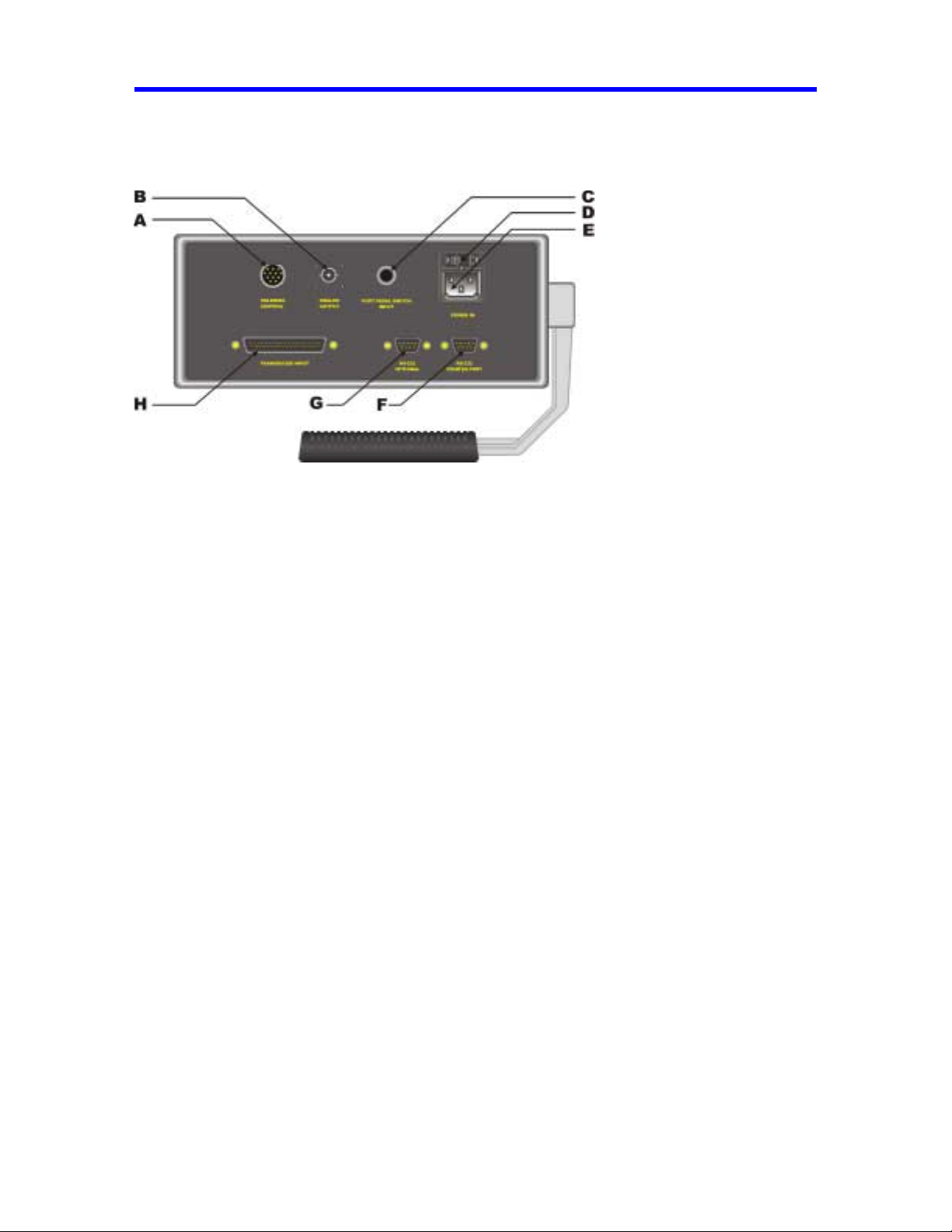
Rear Panel (Input/Output)
Figure 2-5: SURETEST Rear Panel
A- SOLENOID CONTROL (Hirose RM15TRD-12S)
PIN FUNCTION
10 Loader Relay Common
11 Loader Relay CCW Limit
12 Loader Relay CW Limit
B ANALOG OUTPUT (BNC)
Analog output provides a voltage level output that is directly proportional to transducer input,
from -1.8V (full scale counter clockwise) to +1.8V (full scale clockwise). Zero offset +/-100 mV.
Linearity +/-1% of reading. Maximum load = 5 mA.
When using the 4-in-1 transducer, zero output fluctuates until o ne of the transducers is
scan selected by applying 5% of full scale torque.
C- Foot Pedal Switch Input
D- Fuse Holder
Use AC fuse at specified rating only. ( 3.15 Amp).
E- INPUT AC VOLTAGE
Automatic Selection of any AC voltage from 100VAC to 230VAC, 50-60 Hz.
Page 20

FUNCTIONAL DESCRIPTIONS AND SPECIFICATIONS CHAPTER 2
F- PRINTER PORT (DB-9P)
PIN FUNCTION
2 Receive
3 Transmit
5 Ground
G- OPTIONAL (DB-9P)
PIN FUNCTION
2 Receive
3 Transmit
5 Ground
H- TRANSDUCER INPUT (DB-37S)
PIN FUNCTION
1 not used
2 ground
3 smart chip - bit 2
4 smart chip - bit 0
5 single xducer (-) signal
6 single xducer (+) signal
7 ground
8 4-in-1 xduce r (-) signal 2
9 4-in-1 xduce r (+) signal 2
10 ground
11 4-in-1 xducer (-) signal 4
12 4-in-1 xducer (+) signal 4
13 4-in-1 xducer LED 2
14 4-in-1 xducer LED 4
15 loader relay CW limit
16 not used
17 not used
18 ground
19 bridge excitation (+3V)
20 not used
21 smart chip - bit 3
22 smart chip - bit 1
23 ground
24 ground
25 4-in-1 xducer (-) signal 1
26 4-in-1 xducer (+) signal 1
27 ground
28 4-in-1 xducer (-) signal 3
29 4-in-1 xducer (+) signal 3
30 no transducer
31 4-in-1 xducer LED 1
32 4-in-1 xducer LED 3
33 loader relay CCW limit
34 loader relay common
35 Vcc (+5V@100 ma. max)
36 ground
37 bridge excitation (+3V)
Page 21

FUNCTIONAL DESCRIPTIONS AND SPECIFICATIONS CHAPTER 2
SURETEST Transducers
SURETEST transducers provide industry standard square drives. They feature a full
bridge strain-gauge @ 350 Ohms nominal. Full range output is 1500 uE, 9mV
(3mV/V @ 3.0V excitation).
Torque transducers use a built-in EEPROM memory chip that stores range identification
and calibration factors. Calibration of transducers is accomplished using precision torque
bars and certified weights. For additional information, refer to Chapter 5—Calibration.
After a transducer is calibrated, it provides ±0.5% system accuracy with any SURETEST
System. If the transducer and SURETEST are calibrated together, the system accuracy
increases to ±0.25%.
Transducer Dimensions/Transducer Torque Range
Calibration also results in a specified display resolution on the SURETEST. Display
resolution is dependent on the type o f transducer being used. The following table shows
display resolutions for the specified transducer with the force arm.
Display Resolution for Transducers
SURETEST torque transducers can withstand an overload of 110% of full range. The
SURETEST alarms, (audible beep and display "OVER" ) at 110% of rated capacity.
To protect the tool under test or to serve as a fastener installation torque preset alert, the
SURETEST produces a constant audible tone when the input torque exceeds the SET
LOW limit. It then produces a pulsating tone when the input torque exceeds the SET
HIGH limit.
The SURETEST Indicator ignores inputs less than 0.1% of full range in TRACK mode,
2% in PEAK HOLD mode, 7% in FIRST PEAK and POWER TOOL modes.
With the 4-in-1 transducer, the SURETEST System ignores inputs less than 2% of full
range after scan select.
Page 22

FUNCTIONAL DESCRIPTIONS AND SPECIFICATIONS CHAPTER 2
Specifications
SURETEST Torque Calibration System
System Accuracy
±0.25% of reading @ 25°C
(Suretest and transducer calibrated together)
SURETEST Transducers used with, but not calibrated to, another SURETEST provide a system
accuracy of ±0.5% of reading @ 25°C.
Temperature Drift
+0.03%/°C (+0.017%/°F)
Display Accuracy
±0.05% of reading @ 25°C
Temperature
Operating Temperature
10 to 32°C (50 to 90°F)
Storage
-20 to 50°C (-2 to 122°F)
Humidity
Up to 90%, Non-condensing
Temperature Drift
+0.011%/°C, (+0.006%/°F)
Dimensions
Width 10.5“
Height 4.5"
Depth* 10.5"
*Includes handle, feet and connectors
Weight
8 .4 lbs
Fuse:
Amperage, 3.15 amps
Data Storage/Recall w/Date Time Stamp
3,000 measurements
Statistical Analysis
Max, Min, Range, M ean, Sigma N, Sigma, Cp, Cpk
%Error, -NoGo, +NoGo, Histogram.
Page 23

FUNCTIONAL DESCRIPTIONS AND SPECIFICATIONS CHAPTER 2
Printer Serial Output Port
Default: 9600 Baud Rate.
Serial Communications
RS-232 (true)
300—19.2K Baud
8 data bits
1 stop bit
no parity
Computer Serial COM Port (OPTIONAL)
Default: 19,200 Baud Rate.
RS-232 (True)
Analog Output
+(CW)/-(CCW) 1.8V at transducer full range linearity
±1% of reading
Loader Control Relays
Two, normally open, Form A, rated 12VDC @ 1/2A close contact at 110% CW or CCW of torque
transducer range. For additional information refer to Transducer and System specifications.
Display Capacity
(16 bit A/D), 5 digits, ±32,000 counts
Units of Measurement
Torque
ft-lb, in-lb, in-oz, Nm, dNm, cNm, mkg, cmkg
Torque Resolution
Refer to transducer range and display resolution tables in Functional Description of this chapter.
Accuracy
±0.2% of reading @ 25°C, within specified range, when used as prescribed with the 2000-600-02
Loader.
Range and Resolution
Refer to transducer range and display resolution tables in Functional Description of this chapter.
Temperature
Operating Temperature
10 to 32°C (50 to 90°F)
Storage
-20 to 50°C (-2 to 122°F)
Humidity
Up to 90% non-condensing
Temperature Drift
+0.02%/°C (+.011%/°F)
Page 24

SETUP AND PROGRAMMING CHAPTER 3
Manual Loader Specifications
Input Torque (Hand Crank)
8 ft lb maximum (without Motorized control).
Output Torque
2000 ft-lb ±20 degrees rotation maximum
Power Requirements (safety solenoids)
switching From 100 to 230VAC ±10%, @ 50-60 Hz.
Weight (including 2000-100-02 Roll Cab)
1500 lbs.
Optional Calibration Fixturing (Load bars and Weights)
±0.05% accuracy.
3-23
Page 25

SETUP AND PROGRAMMING CHAPTER 3
CHAPTER 3
SETUP AND PROGRAMMING
SURETEST TORQUE CALIBRATION SYSTEM SETUP
MANUAL LO ADER
2000-600-02
MANUAL MECHANICAL LOADER
REAR PANEL CONTROLS
SOLENOID CONTROL CABLE
2000-117
SURETEST
9502-610-02
A
C
D
B
SOLENOID
CONT ROL
TRANSDUC ER INPUT
ANALO G
OUTPUT
FOOT PEDAL SWITCH
INPU T
RS-23 2
OPTIONAL
G
H
I
POWER IN
RS-232
PRINTER PORT
PRINTER CABLE
2000-50-2
ANALOG OUTPUT
FOOT PEDAL SWITCH
950-87
POWER CABLES 110V/220 V AC
PA RT NUM BER :
2000-114 ( U.S.A. )
950-97 ( EUROPE )
950-96 ( AUSTRALIA )
950-95 ( U.K. )
J
SMART
4IN1 TR ANSDUCE R
2000-400-02
TRANSDUCER CABLE
2000-900-120
E
PRINTER
RS-232 COM PORT
F
P. C CABLE
SMART SINGLE TR ANSDUCER
2000-5-02 / 2000-6-02 / 2000-65-02 / 2000-7-02
2000-8-02 / 2000-10-02 / 2000-11-02 / 2000-12-02
2000-13-02 / 2000-14-02
Figure 3-1: SURETEST Torque Tester/Calibrator/Loader Setup
3-24
2000-50-1
K
P.C COMPUTER
RS-232 OPTIONAL
Page 26

SETUP AND PROGRAMMING CHAPTER 3
Back panel connections
A Manual Loader
B Solenoid control cable
C Suretest
D Smart 4-in-1 transducer
E Transducer cable
F Smart single transducer
G Analog Output
H Foot cable switch
I Power cables (110/220 VAC)
J Printer cable
K Personal computer cable
Note: Cable (K) can be connected to Printer Port too.
Setting Up the SURETEST Torque Calibration System
1. Position the roll cabinet on a level floor and lock the wheels.
2. Mount the indicator stand, part number 2000-111-0, to the Loader.
3. Mount the SURETEST base uint to the stand.
4. Connect the solenoid control cable between the Suretest and Loader.
5. Install the appropriate SURETEST transducer to the Loader drive.
6. Install two (2) quick release pins, part number 2000-195-12
7. Connect the transducer cable, part number 2000-900-120, between the Indicator and
transducer.
8. Select the appropriate AC voltage input at the rear of the Loader. Connect the AC power
cables to the Loader. For additional information refer to Chapter 6—Loader Rear Panel
Controls.
9. Install the safety shield to the front of the Loader.
10. Install the reaction pins into the reaction slide on the Loader.
11. Install two Linear ball bearing, part number 2000-173-11.
For testing procedures refer to Chapter 4—Using the Torque Tester.
3-25
Page 27

SETUP AND PROGRAMMING CHAPTER 3
SURETEST Base Unit Controls
Refer to the illustration below when performing the power-up and programming procedures.
Figure 3-2: SURETEST Controls
– SURETEST Graphic LCD Display
– Power Switch
– Front Panel Membrane Function Keys
Powering the Equipment
To power the equipment, press the power button on the front of the SURETEST.
• At POWER ON, the SURETEST performs self-test and momentarily displays the results on the
display.
• With no transducer installed, the display then reads:
• When applying power with the transducer connected, or when connecting a transducer while the
power is on, the display momentarily reads:
ZEROTARE prompt
3-26
Page 28

SETUP AND PROGRAMMING CHAPTER 3
4-in-1 Transducer Installation
When a 4-in-1 transducer is installed, the following is displayed:
All four transducers are scanned as indicated by their associated red LED indicators. To select
one of the transducers, apply at least 5% of its full range torque. To return to the scan mode, press
ENTER.
Single Transducer Installation:
When a single transducer is installed, the following is displayed:
The user can enter Setup mode then proceed to make Torque measurements.
3-27
Page 29

SETUP AND PROGRAMMING CHAPTER 3
Programming Setup
Setting up Date and Time
1. Press (Setup).
2. Scroll down to select Clock Adjust. Press ‘Enter’.
The display reads:
3. Use Left or Right Cursor to select the date/time element to be changed.
4. Increment or decrement the date/time element by repeatedly pushing Up or Down
Cursor. Push and hold Up or Down Cursor to change the display quickly.
5. Press ENTER to update date and time and to return to measurements mode.
Setting Up High and Low Limits Alert
Use SET HIGH and SET LOW to protect the tool under test or serve as a fastener
installation torque preset alert. The SURETEST produces a constant audible tone when
the input torque/force exceeds the SET LOW limit. It then produces a pulsating tone
when the input torque/force exceeds the SET HIGH limit.
It is important to program these limits if statistical analysis is to draw a histogram which
includes reporting out-of-limit parameters.
Changing transducers does not automatically change SET HIGH and SET LOW limits.
Setting High or Low Torque Limits
1. Press (Setup).
2. Scroll down to select Edit limits.
The display reads:
3-28
Page 30

SETUP AND PROGRAMMING CHAPTER 3
3. Press ‘Enter’. The display reads:
4. Press -> or <- to select Hi or Lo limit.
5. Use Left or Right Cursor to select a digit to be changed.
6. Increment or decrement the selected digit by pushing Up or Down Cursor. Push and
hold Up or Down Cursor to change the display quickly.
7. Select and change the next digi t using left and right D IGIT and up and down
Cursor. Continue until all digits are set.
8. Press (Save) to save and to return to measurements mode.
Set-up AUTO CLEAR
Use AUTO CLEAR to program the CLEAR, STORE and SEND functions for
automatic or manual operation. Use these functions in PEAK HOLD, POWER TOOL
and FIRST PEAK modes to STORE torque measurements to memory, CLEAR the
display, and SEND the last measurement captured on the display to the printer or PC.
Auto STORE and SEND are initiated at either AUTO or delayed CLEAR operations.
Use the manual modes to:
• Store the present reading by pushing STORE DATA,
• Clear a captured display by pushing MANUAL CLEAR, or
• Send a measurement to the printer/port by pushing SEND/AUTO SEND.
Use the automatic modes to:
• Store the last measurement, and/or
• Send the last measurement to the printer/port by initiating the auto or delayed
CLEAR function.
AUTO CLEAR can be programmed with a 1 to 9 second delay. Use this feature to
visually note the reading before the display clears. AUTO CLEAR with no delay stores,
prints and/or clears with no delay at the initiation of the next torque input
STORE DATA must be pressed to save the last reading. AUTO CLEAR must be
selected to use AUTO STORE and AUTO SEND.
3-29
Page 31

SETUP AND PROGRAMMING CHAPTER 3
To use the AUTO CLEAR, STORE, or SEND:
1. Press (Setup).
2. Scroll down to select Auto settings.
The display reads:
3. Press ‘Enter’. The display reads:
4. Use Right and Left Cursor to position the reverse-video (*) character under the
function being changed. To program:
CLEAR, press Up or Down Cursor to select "man" (manual clear), "auto"
(automatic), or (delayed automatic) from " 1Sec" to "9Sec" seconds.
STORE, press Up or Down Cursor to select "man" (manual) or "auto" (automatic).
SEND, press Up or Down Cursor to select "man" (manual) or "auto" (automatic).
5. Press ENTER save ‘Auto settings’ and to return to measurements mode.
DATA LIST Memory
When changing sensors, or when creating a new statistical data list, the data list memory
must be cleared. The entire memory list or any single memory location may be
selectively cleared. Clearing from the top of the list decrements the total number of
memory locations. Clearing from inside the list shifts all subsequently taken readings
down from that location and decrements the total number of memory locations.
3-30
Page 32

TORQUE CALIBRATION SYSTEM SETUP CHAPTER 4
Clear Single Memory Location
Use the procedure in this section to clear the a single memory location.
1. Press (Data) to enter data list display. The display reads:
2. Use the Up or Down Cursor to move to the current data. The units and present
memory location are given on the top line. The total number of memory locatio ns
is to the right -- separated by a forward slash (/). The bar graph to the right of the
data list indicates how far in the list the current data display is positioned.
+04.456 in-lb, Time: 23:19 Date: Feb 10, 1999
3. Press (DEL 1) to delete one data entry. The display automatically updates
(decrements by one) the total memory locations on the top line.
Clear All Memory Locations
Use the same above procedure fo r single memory location. Press (Clear) to
memory locations. The following warning appears:
clear all
Select “Yes” to clear all memory.
An audible alarm sounds momentarily. The SURETEST automatically returns to
measurements mode.
Setting Up Printer/PC Ports
The SURETEST is equipped with two RS-232 serial communications ports for use with
an external printer or personal computer. The transfer rate is programmable from 300 to
19.2K baud rate with 8 data bits, 1 stop bit and no parity. The recommended default is
19200 baud for Optional Port and 9600 for Serial Printer.
Communication setup as: (300 – 19200); 8 Data bits; 1 Stop Bit; No Parity
Connect the Printer port to a computer or printer. All (serial) communications will take
place under User’s command(s) Edit Parameters set-up mode.
4-1
Page 33

TORQUE CALIBRATION SYSTEM SETUP CHAPTER 4
CHAPTER 4
SURETEST TORQUE CALIBRATION SYSTEM SETUP
This chapter contains information on how to test, measure, and use the SURETEST
Torque Calibration System.
Testing Torque Wrenches and Drivers
To use the SURETEST Torque Calibration System for torque wrench testing, a
transducer of the appropriate range is fitted to the 2000-600-02 Manual Loader.
The Loader provides a stop that holds the torque wrench handle fixed and rotates the
transducer under the wrench drive. The system applies a precise, monitored torque to the
wrench. For additional information refer to Chapter 6—2000-600-02 Manual Loader.
Selecting a Transducer
When selecting a transducer, choose a single transducer that covers the low to high end
capacity of the torque wrench. Although possible, it is best not to change transducers
between calibration check points. For example: to test or calibrate a 20 to 100 ft lb
wrench, use the 2000-10-02 transducer, which covers the range between 10 and 125 ft lb.
Installing a Transducer
Install the transducer by lining up the red mark with the “TORQUE” label on the loader.
For additional information refer to 2000-600-02 Loader.
• Before changing or replacing transd ucers, adjust SET HIGH and SET LOW limits to
remain within the capacity of the tool under test. For additional information refer to
Chapter 3 Setting Up High and Low Limits Alert .
• If you must retain the statistical analysis, do not change SET HIGH and SET LOW
limits after changing the transducers and be careful not to exceed the wrench capacity.
The procedures provided are general. You may use or establish your own testing
procedures, techniques or standards.
4-1
Page 34

TORQUE CALIBRATION SYSTEM SETUP CHAPTER 4
Dial and Bending Beam Torque Wrenches and Screwdrivers
Be sure the SURETEST transducer is capable of handling the intended torque to avoid
damaging the transducer.
WARNING
Do not use this equipment with the power off. Always turn o n the Base Unit so the
torque values are indicated on the display.
1. T o program the SURETEST B ase Unit refer to Chapter 3 Set Up and Programming.
Use SET HIGH and SET LOW limit alert, data STORE, display CLEAR, printer
SEND and STATistical analysis features.
2. Press Setup then Select Unit to select the desired engineering unit of measure on the
display. It is easiest to match that of the tool under test.
3. Press Setup then Select Mode to select TRACK mode.
4. Install the tool onto the torque transducer-loader. Slowly apply clockwise (CW) to rque
using the Loader crank handle until the indicator displays the full scale torque for the
tool.
Release the torque and repeat twice again to exercise the tool and the transducer.
When applying torque by hand, make sure to hold the drive end of the tool perfectly in
line with the transducer drive to minimize side loading errors.
5. Remove the tool from the transducer-loader and press Zerotare.
6. Press Setup then Select Mode to select PEAK HOLD mode.
7. Reinstall the tool and apply CW torque to the first check point or calibration point
recommended by the manufacturer. If the point is not specified, use the desired working
torque or about 70% of full scale.
8. Read the tool display. The percentage difference between the Suretest and tool readings
should not be greater than the sum of their respective accuracies.
Example:
When tool accuracy is 4% and SURETEST System accuracy is 0.25%, readings should
be within ±4.25%.
9. Release the torque, CLEAR the display, and reapply torque for each of the remaining
check points recommended by the tool manufacturer. If no recommendation is available,
check at 20%, 40%, 60%, 80% and 100% of the tool’s full scale.
10. Repeat steps 4 through 9 in the counter clockwise (CCW) direction.
4-1
Page 35

TORQUE CALIBRATION SYSTEM SETUP CHAPTER 4
Adjustable or Preset “Click” Wrenches and Screwdrivers
Be sure the SURETEST transducer is capable of handling the intended torque to avoid
damaging the transd ucer. Always operate the system with the power on.
WARNING
Do not use this equipment with the power off. Always turn o n the Base Unit so the
torque values are indicated on the display.
1. To program the SURETEST Base Unit refer to Chapter 3–Set Up and Programming.
Use SET HIGH and SET LOW limit alert, data STORE, display CLEAR, printer SEND
and STATistical analysis features.
2. Press Select Unit to select the desired engineering unit of measure as displayed on the
display. It is easiest to match that of the tool under test.
3. Press Setup Select Mode to select TRACK mode.
4. Adjust the to ol for maximum “click” setting. Install the tool on the torque transducerloader. Slowly apply torque using the loader crank handle until the tool clicks or the
Suretest displays 100% of the full scale capacity for the tool. Release the torque and
repeat twice again to exercise the tool and the transducer.
When applying torque by hand, make sure to hold the drive end of the tool perfectly in
line with the transducer drive to minimize side loading errors.
5. Remove the tool from the transducer-loader and press Zerotare.
6. Press Setup then MODE to select FIRST PEAK mode.
When testing “click” screwdrivers, it may be easier to use the PEAK HOLD mode on
the SURETEST to capture the maximum ap p lied torque reading.
7. If featured, adjust the micrometer or preset knob on the tool to the first check point
recommended by the manufacturer, or the desired working torque, or approximately 70%
of its full scale torque.
8. Reinstall the tool and apply torque until the wrench “clicks.”
9. Release the torque and note the FIRST PEAK or PEAK HOLD reading. The
percentage difference between the Suretest reading and tool setting should not be gre ater
than the sum of their respective accuracies.
Example:
When the tool accuracy is 4%, and the SURETEST accuracy is 0.25%, then readings
should be within ±4.25%.).
10. CLEAR the display and reapply torque for each of the remaining check points
recommended by the tool manufacture. If no recommendation is available, test at
minimum torque, 60% and 100% of full scale.
11. Repeat steps 4 through 10 in the opposite direction, if required.
4-1
Page 36

TORQUE CALIBRATION SYSTEM SETUP CHAPTER 4
Testing Power Tools
The dynamic torque characteristic of a power tool and the static torque applied when
using a wrench usually result in different torque readings. Spinning electric and
pneumatic motor armatures contain inertia that produces a higher torque reading than
what is actually absorbed by a practical fastener. The difference is also due to individual
fastener installation characteristics that exhibit anywhere from a gradually increasing rundown torque, (soft-joint) to a free speed, sudden dead stop, (hard-joint). The way in
which a particular operator responds to the tool’s reaction forces can also be reflected in
the resulting torque measurements.
A joint rate simulator is required when testing a power tool to allow start-up rotation of
the tool’s armature. The simulator is experimentally adjusted to replicate the average
joint hardness of the intended work. Joint rate simulators that may be used with
transducers ranging from 50 in lb to 1000 in lb are:
• 50 in lb max, 1/4" internal square drive for use on 2000-6-02 transducer, part number
900-1-0 .
• 400 in lb max, for use on 2000-7-02 transducer, part number 900-2-0, or
• 1000 in lb max, for use on 2000-8-02 transducer, part number 900-3-0.
Be sure to operate any pneumatic or electrical power tool according to the manufacturer’s
recommendations.
Non-Impact Tools
Be sure the SURETEST transducer is capable of handling the intended torque to avoid
damaging the transd ucer. Always operate the system with the power on.
WARNING
Do not use this equipment with the power off. Always turn o n the Base Unit so the
torque values are indicated on the display.
1. To program the SURETEST Base Unit, refer to Chapter 3–Set Up and Programming in
this manual. Use SET HIGH and SET LOW limit alert, data STORE, display CLEAR,
printer SEND and STATistical analysis features.
2. Press Setup then select UNIT to select the desired engineering unit of measure as
displayed on the LCD display. It is easiest to match that of the tool under test.
3. Press Setup then MODE to select TRACK mode.
4. Adjust the power tool to the desired torque output, if possible.
5. Adjust the appropriate joint rate simulator assembly for the desired soft-hard
configuration.
6. Install the joint rate simulator onto the SURETEST transducer, as shown in Figure 4-1.
Secure the transducer set screw, if provided. Loosen the simulator load screw using the
appropriate hex or box wrench.
4-1
Page 37

TORQUE CALIBRATION SYSTEM SETUP CHAPTER 4
Figure 4-1: Power Tool T est Setup
A – Power Tool
B – Joint Rate Simulator
C – Transducer
7. Couple the power tool to the joint rate simulator using the appropriate accessory adaptors
and bit.
8. While holding the power tool drive perfectly in-line with the transducer drive, energize
the tool until its motor stalls or, if featured, the tool clutch slips.
9. Remove the power tool. Loosen the joint rate simulato r load screw.
10. Repeat steps 7 through 9 twice again t o exercise the to ol-simulator assembly and the
SURETEST transducer.
11. Remove the power tool from the loader-transducer and press Zerotare.
12. Press Select Mode to select POWER (TOOL) mode.
4-1
Page 38

TORQUE CALIBRATION SYSTEM SETUP CHAPTER 4
13. W hile holding the power tool drive perfectly in-line with the transducer drive, reinstall
the tool onto the simulator and energize the tool until its motor stalls or, if featured, the
tool clutch slips. Be careful not to add torque by turning the tool by hand.
14. Release the torque and note the Power tool reading on the display.
15. CLEAR the display.
16. Repeat steps 4 through 15 in the opposite direction, if required.
Given the variables typical of power tools and fastener joint dynamics, a number of
readings should be taken and averaged to best determine the accuracy and repea tability
for each tool.
4-1
Page 39

TORQUE CALIBRATION SYSTEM SETUP CHAPTER 4
Displaying Statistical Analysis
The SURETEST B ase Unit accumulates torque measurements in a data list. The list is
created with each AUTO or MANUAL data store entry. Statistical analysis is calculated
on the list, and if SET HIGH and SET LOW limits are established, draws a simple
histogram of the results. These features are very useful in statistical process control
(SPC) management. Statistical analysis can be previewed on the display or sent directly
to a printer/computer port. For additional information on setting up printer or PC ports,
refer to Chapter 3—Set Up and Programming in this manual.
Displaying Statistical Analysis
1. Press Data . Then Format .
Figure 4-2: Statistical Analysis Display
2. Repeatedly press Up or Down Cursor Key to scroll through the LCD display as shown:
Value: 0009
Mean: 07.559 in-lb
Min: 06.768 in-lb
Max: 08.206 in-lb
Range: 01.437 in-lb
SigmaN 00.526 in-lb
Sigma 00.558 in-lb
Cp: 0.3287
Cpk 0.2636
%Err 33.333%
-NoGo 1
+NoGo 2
3. Press Escape to return to measurements mode.
4-1
Page 40

TORQUE CALIBRATION SYSTEM SETUP CHAPTER 4
Printing Statistical Analysis
1. Press Data , then Press Format.
2. Press SEND to display the Print out menu.
Use Down key to select Send Statistics then press Enter to Print.
3. Press Escape to return to measurements mode.
SPC PRINT-OUT
_____________________
SPC listing
_____________________
PART NO.
_____________________
NAME
_____________________
STATISTICAL ANALYSIS
Time : 16/Nov/1998 14:23
** LIMIT DATA **
Set High: 254.85 in-lb
Set Low : 251.55 in-lb
0001 254.45 in-lb
0002 253.91 in-lb
H0003 254.89 in-lb
0004 252.89 in-lb
0005 253.42 in-lb
0006 253.31 in-lb
0007 252.40 in-lb
0008 252.49 in-lb
0009 252.61 in-lb
L0010 251.49 in-lb
4-1
Page 41

TORQUE CALIBRATION SYSTEM SETUP CHAPTER 4
** R E S U L T **
Data : 0010
Max : 254.89 in-lb
Min : 251.49 in-lb
Range : 3.4039 in-lb
Mean : 253.19 in-lb
Sig.n : 0.9755 in-lb
Sigma : 1.0283 in-lb
Cp : 0.5348
Cpk : 0.5317
%Err. : 20.000%
-NoGo : 0001
+NoGo : 0001
H I S T O G R A M
LSL :251.55 in-lb
USL :254.85 in-lb
DIV : 10
-NG0001:X
LSL --------------- A 0000:
B 0000:
C 0002:XX
D 0001:X
E 0001:X
F 0002:XX
G 0000:
H 0001:X
I 0001:X
J 0000:
USL ---------------+NG0001:X
Scale: X =01
A 251.55 in-lb<
B 251.88 in-lb<
C 252.20 in-lb<
D 252.53 in-lb<
E 252.86 in-lb<
F 253.20 in-lb<
G 253.53 in-lb<
H 253.85 in-lb<
I 254.19 in-lb<
J 254.51 in-lb<
254.85 in-lb
Figure 4-4: Sample Statistical Data Printout
4-1
Page 42

TORQUE CALIBRATION SYSTEM SETUP CHAPTER 4
Displaying or Downloading Data List
Torque measurements stored in the data list also include a date and time stamp . Fo r additional
information on setting up printer or PC ports, refer to Chapter 3—Set Up and Programming in this
manual.
Displaying Data List
1. Press DATA.
The display reads:
2. Torque Units of measure are displayed at top of the display with present memory
location/total memory locations to the right. Torque readings are to the left of the Time
and Date.
The selected reading is hightlighted.
3. Use Up and Down key to view the data list.
4. Press Escape to return to measurements mode.
Downloading Data List to Printer
1. Press DATA .
2. Press SEND .
The display reads:
Figure 4-5: Data Download Display.
3. To download the raw d a ta list, Select Send raw data then Press Enter.
4. To download the data list plus date-time stamp, press Down. To select
Send Data, Time/Date Then press Enter to print.
5. Press Escape to return to measurements mode.
4-1
Page 43

CALIBRATION CHAPTER 5
How to Use Analog Output (Rear Panel BNC Connector)
Analog Output on the SURETEST provides a real time voltage level that is
directly proportional to the torque applied to the transducer. It is useful for
direct driving equipment such as analog plotters and chart recorders, or
interfacing to a computer/controller with analog to digital (A/D) data acquisition
capability. Maximum output loading must be less than 5 mA.
The output varies between approximately +1.8 volts, full clockwise (CW) torque
applied and approximately -1.8 volts, full counter clockwise (CCW) torque
applied. Zero offset is within ±100 mv. Linearity is better than ±1% of
reading.
When used with the 4-in-1 transducer, zero output varies with the scan of the
four transducers. Select one of the four by applying at least 5% of its full range
torque to it. Press ENTER to return to scanning.
1. To program the SURETEST Base Unit, refer to Chapter 3—Set Up and
Programming. Use SET HIGH and SET LOW limit alert, data
STORE, display CLEAR, printer SEND and STATistical analysis
features.
2. Press Select Mode to select the TRACK mode.
3. Connect the recording or mo nitoring equipment to the ANALOG
OUTPUT port using a BNC coaxial connector.
4. With no torque applied, measure the ANALOG OUTPUT voltage and
adjust or program yo ur equipment for zero.
5. Apply full range torque to the transducer in the CW direction.
6. Measure the ANALOG OUTPUT voltage and adjust or program your
equipment to display the full range torque value.
7. Apply full range torque to the transducer in the CCW direction.
8. Measure the ANALOG OUTPUT voltage and adjust or program your
equipment to display the full range torque value.
CHAPTER 5
Calibration
The SURETEST Torque Calibration System is factory calibrated using
precision torque test arms, certified weights and laboratory grade
equipment. SURETEST series transducers must be p ositioned
horizontally, with torque applied within ±1 5 degrees of horizontal.
This chapter contains calibration instructions and information fo r the
SURETEST ystem.
5-42
Page 44

CALIBRATION CHAPTER 5
Annual calibration is recommended. Calibration by the user is
recorded in memory and voids factory certification. Contact your
authorized CDI sales representative for calibratio n and repair
services.
If extreme calibration precision is required , refer to Correction
Factors on Test Weights in this chapter.
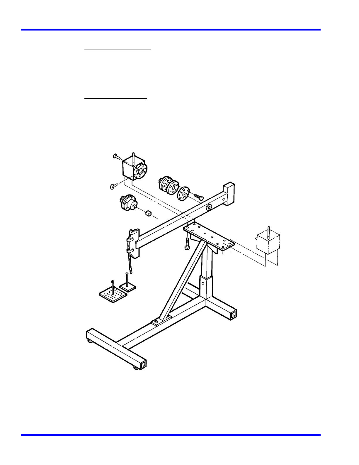
Mounting Details
Single Transducer Mounting Detail for Calibration
Single transducer calibration requires the use of a reaction stand and
transducer calibration block.
As shown in Figure 5.1, the transducer is secured to the calibration
block with two quick release pins.
• Both pins must be installed for safety and stability of the mount.
• The white mark on the transducer is aligned in the up position.
Figure 5-1: Single Low Torque Transducer Mounting Detail
5-43
Page 45
CALIBRATION CHAPTER 5
Torque Under 250 ft lb
Mount the calibration block at the center of the stand with two 1/2-13 socket head cap
screws with test bars that are 10" or shorter. Install these screws using the supplied torque
wrench and 3/8-3/8 socket driver adapter. Use this configuration for up to 250 ft lb of
applied torque. A 1/2" to 3/8" reducer is required when mounting the 10" arm to
transducers having 3/8" drives.
Torque Over 250 ft lb
For torque calibration above 250 ft lb, the calibration block is moved to the left for CCW
loading and to the right for CW loading. The torque arm is always extended over the front
of the reaction bracket for both CW and CCW torque applications. In this configuration,
useful up to 2000 ft lb, the calibration block is secured to the stand using four 1/2-13
socket head cap screws, each torqued to 75 ft lb. For additional information refer to
Figure 5-2.
Figure 5-2: Single High Torque Transducer Mounting Detail
The 2000-12-02, 600 ft lb transducer, requires the 1-1/4" to 3/4" drive reducer, supplied, to couple to
the 40" test bar.
5-44
Page 46

CALIBRATION CHAPTER 5
WARNING
Always position the 40" arm over the front of the stand as shown. Never extend the test arm
behind the stand because the stand will tip over when we ights are applied.
The 40" test arm is coupled to the 2000-13-02, 1000 ft lb, and 2000-14-02, 2000 ft lb transducers
using a 1-1/4" drive adapter plate.
1. Remove the internal drive adapter plate and bottom plate from the transducer using the
torque wrench, ratchet head and 3/8-3/8 hex bit or 3/4" open end adapter supplied.
2. Remove separated adapter from calibration block.
3. Attach transducer to the calibration block so that red mark on transducer lines up with white dot in
left bottom corner on calibration block. Tighten six 1/2"-13 hex head bolts to 75 ft lb torque.
4. Attach the 1-1/4" drive adapter plate using six 1/2"x13 hex head bolts, each torqued to 75 ft lb
using the torque wrench, and 3/4” open end adapter, supplied.
5. After calibration, re-install the internal drive plate and bottom plate using appropriate 1/2"x13
screws, torquing them to 75 ft lb. Also re-install the separated adapter to the calibration block.
Appropriate hangers and weights are listed in the calibration check point table in this chapter.
Notice that the weight of the hanger is included in all measurements. The hanger must be removed
to set ZERO TARE on the Indicator.
4-in-1 Transducer Mounting Detail for Calibration
The 4-in-1 transducer mounts upright with integral transducers in the horizontal position. This
transducer may be mounted to a
• Wall using four 1/4" bolts torqued to 10 ft lb, or
• Sturdy table using a ri ght angle bracket. Refer to Figure 5-3.
Figure 5-3: 4-in-1 Transducer Mounting Detail
5-45
Page 47

CALIBRATION CHAPTER 5
The 4-in-1 transducer may also be mounted to the calibration stand, shown in Figure 5-2, using the
standoff fixture and bracket assembly. For this mounting configuration the two slide knobs must be
loosened and four 5/16-18 bolts attached to secure the 4-in-1 transducer to the bracket assembly.
Quick Check
WARNING
Always be alert to the potential for personal injury that may be caused by excessive
torque applications, careless handling of heavy weights, and out-of-balance or unsafe
weight distribution.
1. With the SURETEST ON, select TRACK mode, and select the UNITs of measure appropriate to
the transducer as specified in the calibration check point table in this chapter.
2. Install the transducer to be checked and allow a 5 minute warm up period to stabilize the electronic
circuits and transducer elements.
3. Transducers are mounted horizontally for calibration as instructed in Mounting Details in this
chapter. Mount the 4-in-1 transducer to a sturdy bench using the bracket provided. Mount single
transducers horizontally using the accessory stand and block. Attach the specified torque test bar,
wheel or butterfly, secured with its drive retention screw, and install the specified hanger for
clockwise (CW) torque application.
4. Apply and remove the full range torque for the transducer three times.
5. Remove the weights and hanger, but leave the arm attached, and press ZERO TARE.
6. At each of the check points specified for the transducer in the calibration check point
table (in this chapter), apply torque in the CW direction and verify the display readings are
within 0.25% of applied torque. If any reading is out of specification, proceed to Calibrating
SURETEST Torque Transduc e rs in this chapter.
7. Repeat Step s 3 through 6 in the co unter clockwise (CCW) direction.
When using the 2-1/2" or 5" test wheel, a small “S” hook is supplied to provide a positive zero bias
in the direction (CW or CCW) that the calibration is performed. Do not remove the “S” hook when
setting zero tare.
5-46
Page 48

CALIBRATION CHAPTER 5
Suggested Transducer Calibration Check Points, Bars, Hangers and Weights
(Sheet 1 of 2)
Part Bar Hanger Calibration Check Weights to Add Total
No. Ra nge Length Weight Points Points (n) = more than 1 Weight
2000-5-02
15-200 in oz 2.5" none 15.0 in oz 2 oz, 4 oz 6 oz
2.5" 1/2 lb 1 20.0 in oz 20.0 in oz none 1/2 lb
2.5" 1/2 lb 2 40.0 in oz 40.0 in oz 1/2 lb 1 lb
2.5" 1/2 lb 3 80.0 in oz 80.0 in oz 1/2 lb, 1 lb 2 lb
2.5" 1/2 lb 4 120.0 in oz 120.0 in oz 1/2 lb, (2) 1 lb 3 lb
2.5" 1/2 lb 5 200.0 in oz 200.0 in oz 1/2 lb, (2) 2 lb 5 lb
2000-6-02
4-50 in lb 5.0" 1/2 lb 4.0 in.lb 0.3 oz, 0.5 oz, 4 oz 0.8 lb
5.0" 1/2 lb 1 5.0 in lb 5.0 in lb 1/2 lb 1 lb
5.0" 1/2 lb 2 10.0 in lb 10.0 in lb 1/2 lb, 1 lb 2 lb
5.0" 1/2 lb 3 20.0 in lb 20.0 in lb 1/2 lb, 1 lb, 2 lb 4 lb
5.0" 1/2 lb 4 30.0 in lb 30.0 in lb 1/2 lb, 1 lb, (2) 2 lb 6 lb
5.0" 1/2 lb 5 50.0 in lb 50.0 in lb 1/2 lb, 1 lb, (4) 2 lb 10 lb
2000-65-02
15-150 in lb 5.0" 1/2 lb 1 15.0 in lb 15.0 in lb 1/2 lb, 2 lb 3 lb
5.0" 1/2 lb 2 30.0 in lb 30.0 in lb 1/2 lb, 1 lb, (2) 2 lb 6 lb
5.0" 1/2 lb 3 60.0 in lb 60.0 in lb 1/2 lb, 1 lb, (2) 5 lb 12 lb
5.0" 1/2 lb 4 90.0 in lb 90.0 in lb 1/2 lb, 2 lb, (3) 5 lb 18 lb
5.0" 1/2 lb 5 150.0 in lb 150.0 in lb 1/2 lb, (2) 2 lb, (5) 5 lb 30 lb
2000-7-02
30-400 in lb 10.0" 1/2 lb 30.0 in lb 1/2 lb, 2lb 3 lb
10.0" 1/2 lb 1 40.0 in lb 40.0 in lb 1/2 lb, 1 lb, 2 lb 4 lb
10.0" 1/2 lb 2 80.0 in lb 80.0 in lb 1/2 lb, 2 lb, 5 lb 8 lb
10.0" 1/2 lb 3 160.0 in lb 160.0 in lb 1/2 lb, (3) 5 lb 16 lb
10.0" 1/2 lb 4 240.0 in lb 240.0 in lb 1/2 lb, 1 lb, 2 lb, (4) 5 lb 24 lb
10.0" 1/2 lb 5 400.0 in lb 400.0 in lb 1/2 lb, 1 lb, (4) 2 lb, (6) 5 lb 40 lb
2000-8-02
80-1000 in lb 10.0" 7-1/2 lb 80.0 in lb 1/2 lb 8 lb
10.0" 7-1/2 lb 1 100.0 in lb 100.0 in lb 1/2 lb, 2 lb 10 lb
10.0" 7-1/2 lb 2 200.0 in lb 200.0 in lb 1/2 lb, 2 lb, (2)5 lb 20 lb
10.0" 7-1/2 lb 3 400.0 in lb 400.0 in lb 1/2 lb, 2 lb, (2)5 lb, (2)10 lb 40 lb
10.0" 7-1/2 lb 4 600.0 in lb 600.0 in lb 1/2 lb, 2 lb, (2)5 lb, (4)10 lb 60 lb
10.0" 7-1/2 lb 5 1000 in lb 1000 in lb 1/2 lb, 2 lb, (2)5 lb, (4)10 lb, (2)20 lb 100 lb
2000-10-02
10-125 ft lb 10.0" 7-1/2 lb 10 ft lb 1/2 lb, (2) 2 lb 12 lb
10.0" 15 lb 1 12.5 ft lb 12.5 ft lb none 15 lb
10.0" 15 lb 2 25.0 ft lb 25.0 ft lb (3) 5 lb 30 lb
10.0" 15 lb 3 50.0 ft lb 50.0 ft lb 5 lb, (2) 10 lb, 20 lb 60 lb
10.0" 15 lb 4 75.0 ft lb 75.0 ft lb (3) 5 lb, (2) 10 lb, (2) 20 lb 90 lb
10.0" 15 lb 5 125.0 ft lb 125.0 ft lb 5 lb, 10 lb, 20 lb, (2) 50 lb 150 lb
2000-11-02
20-250 ft lb 10.0" 15 lb 20.0 ft lb (2) 2 lb, 5 lb 24 lb
10.0" 15 lb 1 25.0 ft lb 25.0 ft lb 5 lb, 10 lb 30 lb
10.0" 15 lb 2 50.0 ft. lb 50.0 ft. lb 5 lb, (2) 20 lb 60 lb
10.0" 15 lb 3 100.0 ft. lb 100.0 ft. lb 5 lb, (2) 50 lb 120 lb
10.0" 15 lb 4 150.0 ft. lb 150.0 ft. lb 5 lb, (3) 20 lb, (2) 50 lb 180 lb
10.0" 15 lb 5 250.0 ft. lb 250.0 ft. lb 5 lb, (4) 20 lb, (4) 50 lb 300 lb
5-47
Page 49

CALIBRATION CHAPTER 5
Suggested Transducer Calibration Check Points, Bars, Hangers and Weights
(Sheet 2 of 2)
Part Bar Hanger Calibration Check Weights to Add Total
No. Ra nge Length Weight Points Points (n) = more than 1 Weight
2000-12-02
60-600 ft lb 40" 15 lb 1 60.0 ft lb 60.0 ft lb 1 lb, 2 lb 18 lb
40" 15 lb 2 120.0 ft lb 120.0 ft lb 1 lb, (2) 10 lb 36 lb
40" 15 lb 3 240.0 ft lb 240.0 ft lb 2 lb, 5 lb, 10 lb, (2) 20 lb 72 lb
40" 15 lb 4 360.0 ft lb 360.0 ft lb 1 lb, 2 lb, 10 lb, (4) 20 lb 108 lb
40" 15 lb 5 600.0 ft lb 600.0 ft lb 5 lb, (3) 20 lb, (2) 50 lb 180 lb
2000-13-02
100-1000 ft lb 40" 15 lb 1 100.0 ft lb 100.0 ft lb 5 lb, 10 lb 30 lb
40" 15 lb 2 200.0 ft lb 200.0 ft lb 5 lb, (2) 20 lb 60 lb
40" 15 lb 3 400.0 ft lb 400.0 ft lb 5 lb, (5) 20 lb 120 lb
40" 15 lb 4 600.0 ft lb 600.0 ft lb 5 lb, (2) 10 lb, (2) 20, (2) 50 lb 180 lb
40" 15 lb 5 1000.0 ft lb 1000.0 ft lb 5 lb, (4) 20 lb, (4) 50 lb 300 lb
2000-14-02
200-2000 ft lb 40" 50 lb 1 200.0 ft lb 200.0 ft lb (2) 5 lb 60 lb
40" 50 lb 2 400.0 ft lb 400.0 ft lb 20 lb, 50 lb 120 lb
40" 50 lb 3 800.0 ft lb 800.0 ft lb (2)5 lb, (4)20 lb, (2)50 lb 240 lb
40" 50 lb 4 1200.0 ft lb 1200.0 ft lb (2)5 lb, (5)20 lb (4)50 lb 360 lb
40" 50 lb 5 2000.0 ft lb 2000.0 ft lb (2)5 lb, (4)10 lb, (5)20 lb, (8)50 lb 600 lb
2000-400-02
4-50 in lb 5" 1/2 lb 4.0 in lb 0.3 oz, 0.5 oz, 4 oz 0.8 lb
(4-in-1) 5" 1/2 lb 1 5.0 in lb 5.0 in lb 1/2 lb 1 lb
5" 1/2 lb 2 10.0 in lb 10.0 in lb 1/2 lb, 1 lb 2 lb
5" 1/2 lb 3 20.0 in lb 20.0 in lb 1/2 lb, 1 lb, 2 lb 4 lb
5" 1/2 lb 4 30.0 in lb 30.0 in lb 1/2 lb, 1 lb, (2) 2 lb 6 lb
5" 1/2 lb 5 50.0 in lb 50.0 in lb 1/2 lb, 1 lb, (4) 2 lb 10 lb
30-400 in lb 10" 1/2 lb 30.0 in lb 1/2 lb, 2 lb 3 lb
10" 1/2 lb 1 40.0 in lb 40.0 in lb 1/2 lb, 1 lb, 2 lb 4 lb
10" 1/2 lb 2 80.0 in lb 80.0 in lb 1/2 lb, 1 lb, (3) 2 lb 8 lb
10" 1/2 lb 3 160.0 in lb 160.0 in lb 1/2 lb, (3) 5 lb 16 lb
10" 1/2 lb 4 240.0 in lb 240.0 in lb 1/2 lb,1 lb, 2 lb, (4) 5 lb 24 lb
10" 1/2 lb 5 400.0 in lb 400.0 in lb 1/2 lb,1 lb (4) 2 lb, (6) 5 lb 40 lb
80-1000 in lb 10" 7-1/2 lb 80.0 in lb 1/2 lb 8 lb
10" 7-1/2 lb 1 100.0 in lb 100.0 in lb 1/2 lb, 2 lb 10 lb
10" 7-1/2 lb 2 200.0 in lb 200.0 in lb 1/2 lb, 2 lb, (2)5 lb 20 lb
10" 7-1/2 lb 3 400.0 in lb 400.0 in lb 1/2 lb, 2 lb, (2)5 lb, (2)10 lb 40 lb
10" 7-1/2 lb 4 600.0 in lb 600.0 in lb 1/2 lb, 2 lb, (2)5 lb, (4)10 lb 60 lb
10" 7-1/2 lb 5 1000 in lb 1000 in lb 1/2 lb, 2 lb, (2)5 lb, (4)10 lb, (2)20 100 lb
20-250 ft lb 10" 15 lb 20.0 ft lb (2) 2 lb, 5 lb 24 lb
10" 15 lb 1 25.0 ft lb 25.0 ft lb 5 lb, 10 lb 30 lb
10" 15 lb 2 50.0 ft. lb 50.0 ft. lb 5 lb, (2) 20 lb 60 lb
10" 15 lb 3 100.0 ft. lb 100.0 ft. lb 5 lb, (2) 50 lb 120 lb
10" 15 lb 4 150.0 ft. lb 150.0 ft. lb 5 lb, (3) 20 lb, (2) 50 lb 180 lb
10" 15 lb 5 250.0 ft. lb 250.0 ft. lb 5 lb, (4) 20 lb, (4) 50 lb 300 lb
5-48
Page 50

CALIBRATION CHAPTER 5
Torque Calibrations
SURETEST New Transducer Calibration
Improper calibration can result in torque measurement errors. Follow these procedures precisely.
If an error is made in the procedure, turn the Suretest off and begin again. Users are responsible for
the results of their transducer calibration.
SURETEST series Torque transducers can only be calibrated using the SURETEST Base Unit.
Calibration data is calculated and then stored in the FLASH memory chip of the transducer by the
microcontroller in the Indicator.
WARNING
Always be alert to the potential for personal injury and equipment damage that may be
caused by excessive torque applications, careless handling of heavy weights, and out-ofbalance or unsafe weight distribution.
Equipment
• Precision test arms and certified calibration weights.
• Test stand.
Procedure
1. Turn the SURETEST ON. Refer to the calibration check point table in this chapter for the
transducer calibration check points, as well as the specified arms, hangers and weights.
2. Install the transducer being calibrated and allow a 5 minute warm up period to stabilize the
electronic circuits and transducer elements.
3. Mount the 4-in-1 transducer upright, drives horizontal, as shown in Figure 5-3, or mount
single transducers horizontally using the accessory stand and block as detailed in Figure 5-2.
Attach the specified torque arm, secured with the drive retention screw, and install the
specified hanger for clockwise (CW) torque application. Use the “S” hook on the 2-1/2" or 5" bars.
4. Apply and release full scale torque to the transducer three times in the CW direction, then remove
the weights and hanger. Leave the torque arm installed. Press Soft Key Setup to select Setup
Menu.
5. Use DOWN Cursor key to scroll down to Calibration Item. Press ‘ENTER’.
5-49
Page 51

CALIBRATION CHAPTER 5
6. Enter the following code into the display using the Cursor Keys: 5222
( Left / Right to select digit ; Up / Down = Increment / Decrement value ; ‘Enter’ to accept)
Calibration CW:
7. Select Calibrate CW. Press ‘ENTER’.
A warning is displayed.
Select ‘
8. Using the Up or Down Cursor keys, enter “
Using the Up or Down Cursor keys, enter “
9. Press ENTER. The disp lay reads:
Yes’. Press ‘Enter’ .
1” for a single transducer .
4” for the 4-in-1 transducer.
5-50
Page 52

CALIBRATION CHAPTER 5
Press F2 key and select the desired torque unit.
10. Using the Up and Down Cursor keys, enter the Full Scale value for the 4-in-1 transducer to calibrate.
Possible values are:
1 = 50 in-lb
2 = 400 in-lb
3 = 1000 in-lb
4 = 250 ft-lb
( For 4 in 1 Transd ucers display shows : CHECKING TRANSDUCER.)
Apply load until “ Full Scale [units] shows on display.
11. Press ENTER. To accept 50 in.lb Transducer.
Press any key to zerotare.
12. Press any key. The LCD displays:
13. Apply torque using the precision arm, hanger or certified weights listed as calibration point 1 in the
calibration check point table in this chapter. When the reading is stable, push and hold the Up or Down Cursor Keys
to get the correct torque value reading. Repeat the procedure for points 2,3,4, and 5 of the same table.
Apply 10% Torque = 5 in.lb
5-51
Page 53

CALIBRATION CHAPTER 5
13. P ress (Accept) to accept the calibration value (1
st
Cal point).
Apply 20% Torque = 10 in.lb
14. Press (Accept) to accept the calibration value (2
nd
Cal point) .
Apply 40% Torque = 20 in.lb
16. Press (Accept) to accept the calibration value (3
rd
Cal point) .
Apply 60% Torque = 30 in.lb
17. P r ess (Accept) to accept the calibration value (4
th
Cal point) .
Apply 100% Torque = 50 in.lb
18. P r ess (Accept) to accept the calibration value (5
th
Cal point) .
The display will show: Saving …. then show the Calibration table.
19. Remove all weights and the arm.
Press any key, go back to Select mode.
Calibration CCW:
(Go to step 7 then select CCW)
20. Select " Calibrate CCW” on the LCD display.
Apply and release full scale torque to the transducer three times in the CCW direction then
remove the weights and hanger, wait for about 15 seconds.
21. Repeat steps 12 through 19, applying al l torque in the counter clockwise (CCW) direction.
5-52
Page 54

CALIBRATION CHAPTER 5
22. All readings show minus sign (-). Press F1 twice to return to measurement mode.
SURETEST Indicator Calibration
WARNING:
Improper calibration can result in torque measurement errors. Follow these
procedures precisely. If an error is made in the procedure, turn the Suretest off and
begin again. Users are responsible for the results of their calibration.
Equipment
• Laboratory grade millivolt meter for calibration measurements capable of resolving 1/100
millivolts.
• Calibration fi xt ure as shown in Figure 5-2.
Calibration fixture Figure 5-2.
Procedure
1. With the power off, plug the calibration fixture into the TRANSDUCER INPUT
connector at the back of the SURETEST Base Unit.
2. Turn the power on. After initialization, the LCD display reads:
No Transducer Connected
3. Press Soft Key Setup to get to Setup Menu.
5-53
Page 55

CALIBRATION CHAPTER 5
Use DOWN Cursor key to scroll down to Calibration Item. Press ‘ENTER ’.
The display reads:
4. Enter the following code into the display using the Cursor Keys:
( Left / Right to select digit ; Up / Down = Increment / Decrement value ; ‘Enter’ to accept)
5111
Calibrate tester
Using a laboratory millivolt meter, measure the voltage across pin 2 (ground) and 19 (Gage
Excitation) of the calibration fixture.
The display reads:
Example:
3.0211 volts
Program the measured voltage into the SURETEST Base Unit using the Cursor Keys. (Use Up,
Down, Left and Right Cursor Keys to match the Suretest display to the millivolt-meter).
Then Press ‘Enter’ to accept.
5. Next, the display reads:
Short pins 5 and 6 together on the calibration fixture. Then hit Enter key.
6. Next, the display reads:
Remove the short between pins 5 and 6 of the calibration fixture.
5-54
Page 56

CALIBRATION CHAPTER 5
Using a laboratory millivolt meter, measur e the voltage across pins 5 and 6.
Example: 08.0622 mV
7. Program the measured voltage into the SURETEST Indicator as demonstrated in the example,
“+08.0622” by pushing and holding the Up or Down Cursor keys.
8. Press ENTER. The display momentarily reads:
SAVING...
9. Turn the power to OFF. Remove the calibration fixture.
5-55
Page 57

MANUAL LOADER CHAPTER 6
Gravitational Effects
Correction Factors on Test Weights
Weights used in torque calibration are affected by their acceleration due to:
• Altitude above or below sea level, and
• Latitude on earth between the equator and the poles.
Test bars are not affected by these conditions. The accuracy of torque wrenches
and testers does not change due to changes in geographic location. Only when
using weights must correction factors be considered. After an analysis is made
for a given location, it is often found that the correction factor is insignificant.
Two methods of correction are provided. They are:
• Correction factor for check point readings adjusts the calibration readings
without changing the ap plied weight.
• Correction factor for weights adjusts the weight applied without changing check
point readings. For additional information refer to Gravitational Charts in this
chapter.
Gravitational Charts
The charts in this section are taken from CRC Handbook of Chemistry and
Physics, 58th Edition. CRC Pr ess, Inc., 18901 Cranswood Parkway. Cleveland,
Ohio 44128.
Acceleration Due to Gravity for Sea Level at Various
Latitudes
Latitude, degrees Acceleration, cm/sec2 Latitude, degrees
Acceleration, cm/sec2
0 978.039 46 980.711
5 978.078 48 980.892
10 978.195 50 981.071
15 978.384 52 981.247
20 978.641 54 981.422
25 978.960 56 981.592
30 979.329 58 981.757
32 979.487 60 981.918
34 979.652 65 982.288
36 979.822 70 982.608
38 979.995 75 982.868
40 980.171 80 983.059
42 980.350 85 983.178
44 980.531 90 983.217
Free Air Correction for Altitude
Altitude, m Correction, cm/sec2
200 -0.0617
300 -0.0926
400 -0.1234
6-56
Page 58

MANUAL LOADER CHAPTER 6
500 -0.1543
600 -0.1852
700 -0.2160
800 -0.2469
900 -0.2777
Correction Factor for Check Point Readings
1. Determine latitude and altitude. Obtain information from local geological survey office or
library.
2. Find the acceleration due to gravity for sea level from its chart.
3. Subtract the free air correction for altitude from its chart.
4. Divide the result calculated in step 3 by the standard gravitational factor
980.665cm/sec/sec.
5. Multiply the check point in the calibration charts by the factor calculated in step 4 to
obtain the corrected
check point readings while using the original weight.
Correction Factor for Weights
1. Determine latitude and altitude. Obtain information from local geological survey office
or library.
2. Find the acceleration due to gravity for sea level from its chart.
2. Subtract the free air correction for altitude from its chart.
3. Divide the result, calculated in step 3, by the standard gravitational factor 980.665
cm/sec/sec.
4. Calculate the reverse of the calculation in step 4 by dividing it into 1.
5. Multiply the weight given for each check point in the calibration charts by the inverse
factor, calculated in
step 5, and use this corrected weight with the original check point readings.
CHAPTER 6
Manual Loader (2000-600-02)
The 2000-600-02 Manual Loader is designed as an integral component of the CDI SURETEST
Torque Calibration System providing a precision output torque of up to 2000 ft lb while requiring
only 8 ft lb input.
6-57
Page 59

MANUAL LOADER CHAPTER 6
Application
The loader is a laboratory grade instrument used for testing and calibrating all torque wrenches,
drivers, torque multiplier s, non-impact pneumatic and electric nut runners
Power
To activate the limit solenoids that protect the transducers from overload, the loader
requires AC power, 115/230VAC, 50 to 60 Hz, 1.0 amps.
WARNING
Do not use this equipment with the power off. Alw ays turn on the Suretest Base Unit and
loader so the torque and load values are indicated on the display. The safety relays only
work when the power is on.
Transducer Rotation
The manual hand crank provide s up to 20° of transducer rotation in both clockwise (CW) a nd
counter clockwise (CCW) directions.
SURETEST Torque Calibration System
Components included in System are:
• 5000-ST Base Unit (Suretest)
• 2000-600-02 Loader, and
• 2000-100-02 Roll Cabinet.
When the 2000-600-02 Manual Loader interfaces with the 5000-ST Base Unit and the
SURETEST series of torque transducers, the SURETEST Torque Calibration system provides
precision loading, monitoring and data acquisition of torque, within ± 0.25% accuracy.
System capabilities include, data storage, retrieval, statistical analysis and automatic downloading
to a printer or computer.
Torque transducers, purchased separately, are available in ranges from 15-200 in oz, to 200-2000
ft lb. The SURETEST Torque Calibration system features accessory calibration equipment
including precision torque bars, certified weights, calibration mounts and stands and torque
multipliers.
The 2000-600-02 includes a CDI roll cabinet, part number 2000-100-02, with heavy duty casters
and nine drawers with ball bearing slides for transducer and calibration equipment storage. An
extendable swivel indicator stand accepts mounting of the SURETEST Base Unit for operator
convenience.
6-58
Page 60

MANUAL LOADER CHAPTER 6
Functional Description
This section describes major hardware components of the torque tester, including the:
• Torque tester calibrator,
• 2000-600-02 Manual Loader,
• Loader rear panel controls,
• Ball handle adaptor,
• 4-in-1 transducer (accessory), and
• Extension arm (accessory).
Torque Tester/Calibrator
The 2000-600-02 Manual Loader mounts on a CDI roll cabinet, part number 2000-100-02. An
indicator stand mounts onto the loader.
Figure 6-1: 2000-600-02 Manual Loader
A- Indicator Stand
B- Safety Shield
C- Hand Crank
D-Transduce r Mounting
6-59
Page 61

MANUAL LOADER CHAPTER 6
Use the 2000-600-02 Manual Loader to test torque wrenches. Refer to Figure 6-2 for an exploded
view of the Lo ader and components.
Figure 6-2: 2000-600-02 Manual Loader, Exploded View
A- Transducer Mounting
A transducer facilitates the low-to-high ranges of the wrench under test. The transducer must be
installed into the loader by lining up the red mark with the "TORQUE" label on the loader and
securing it using two quick release pins.
6-60
Page 62

MANUAL LOADER CHAPTER 6
IMPORTANT
The connector on single transducer cables contains the EEPROM calibration memory
chip. Never attempt to remove the connector from the transducer.
B- Hand Crank
Turn hand crank on the loader to apply torque. 2000 ft lbs of torque are generated with only 8 ftlbs of manual torque applied.
C- Reaction Block
The reaction block is positioned so that the reaction pins straddle the wrench handle at the hand
hold position specified on the wrench.
D- Linear Bearings
May be slipped over the reaction pins to reduce friction when testing very small or high resolution
electronic wrenches.
E- Reaction Pins
Hold the reaction block in place.
IMPORTANT
Adjustable stops on the reaction pins may be raised or lowered to level the wrench prior to
loading. Do not place a second stop above the wrench handle. It is normal for the wrench
handle to rise as it levels itself under load.
F- Drive Adaptor
A drive adaptor couples the wrench to the transducer. Low torque SURETEST series transducers
use an internal-internal drive adaptor and high torque SURETEST transducers may use an
adaptor/reducer.
G- Transducer (Accessory)
The loader accepts all SURETEST series single transducers directly. An optional 2000-400-02 4in-1 transducer can be mounted using a 2000-500-02 adaptor kit. For more information, refer to
Appendix A–Accessories.
6-61
Page 63

MANUAL LOADER CHAPTER 6
Loader Rear Panel Controls
The 2000-600-02 Manual Loader rear panel is shown in Figure 6-3.
Figure 6-3: 2000-600-02 Manual Loader Rear Panel Controls
A- Fuse
The loader power supply is protected with a 1 amp slo-blow fuse.
B- Voltage Select
A selector switch allows the loader to use both 110VAC or 220VAC.
C- AC Power Input
The loader uses either 110VAC or 220VAC power. The loader connects to the SURETEST Base
Unit by the 2000-117 cable.
D- Solenoid Control
AC power is applied to the loader to operate a pair of safety solenoids used to protect the
transducers from overloading. Should the applied torque exceed 110% of the transducer capacity,
in either CW or CCW directions, the Base Unit energizes the solenoids to lock the hand crank.
6-62
Page 64

MANUAL LOADER CHAPTER 6
Ball Handle Adaptor
Wrenches featuring a ball handle are fixtured using the ball hand le reaction adaptor shown in
Figure 6-4. Install the adaptor onto the reaction slide using both reaction pins. Fix the adaptor
height with the threaded knob.
Figure 6-4: Ball Handle Adaptor
6-63
Page 65

MANUAL LOADER CHAPTER 6
4-in-1 Transducer (Accessory)
The 4-in-1 transducer is mounted to the loader using the standoff fixture and bracket assembly as
shown in Figure 6-5.
Figure 6-5: 4-in-1 Transducer on 2000-600-02 Manual Loader
A- Quick Release Pins
Four quick release pins must be installed. The first two secure the standoff fixture to the loader
and the second two lock the adaptor to the transducer bracket.
B- Loader Standoff (under bracket)
The standoff and bracket must be installed into the loader by lining up the holes of the standoff to
the holes of the loader.
C & D- Bracket Knobs
Two knobs on the bracket are used to align the selected transducer over the loader drive. Tighten
the left knob (D) first, then the top knob (C). The wr ench or dr iver to be tested is then coupled to
the selected transducer using an internal-internal adaptor.
6-64
Page 66

MANUAL LOADER CHAPTER 6
E- 4-in-1 Adapter Bracket
Holds the 4-in-1 transducer horizontal to the loader.
6-65
Page 67

MANUAL LOADER CHAPTER 6
Extension Arm (Accessory)
The 2000-600-02 Manual Loader accepts torque wrenches up to 80" in length. The extension arm
is attached as shown in Figure 6-6. A quick release pin is used at the end of the arm to capture the
reaction pin slide assembly.
Figure 6-6: 2000-600-02 Manual Loader Extension Arm
6-66
Page 68

ACCESSORIES APPENDIX A
Types of Loader Testing
Torque Driver Testing
An accessory torque screwdriver testing kit, 2000-750-02, is available for use in testing or
calibrating most torque screwdrivers and "T" handled drivers. In addition to providing perfect
driver-transducer alignment, it allows the use of the 2000-600-02 loader crank for precision torque
application.
Certain torque screwdrivers, "T" handled drivers, electric o r pneumatic nut runners, and nonimpact power tools must be tested by hand. Double check to be sure that the transducer you
choose is capable of handling the maximum torque that you will apply. Hold the tool exactly in
line with the transducer drive while testing. Off-a xis side loading may compromise the test or
calibration of the tool.
Torque Multiplier Testing
The 2000-600-02 Manual Loader and SURETEST series transducers can be configur ed to test
certain torque multipliers. SURETEST also provides measurement, display, storage and statistical
analysis of multiplier output torque to 2,000 ft lbs.
In practice, the multiplier is attached to the loader using custom fixturing. The operator provides
input torque with an appropriate wrench, breaker bar or the multiplier’s integral hand crank.
Various mounting fixtures, adaptors, reaction stops and pins are available for testing the most
common torque multipliers. Ask your CDI sales representative for design assistance.
Appendix A
Accessories
This appendix contains information on replacement parts and accessories that are
available from Consolidated Devices, Inc., 1-800-525-6319.
Refer to Figure A-1, below, for drawer and cutout arrangement information.
A-67
Page 69

ACCESSORIES APPENDIX A
Figure A-1: Roll Cabi net Drawer Arrangement
A-68
Page 70

ACCESSORIES APPENDIX A
SURETEST Torque Calibration System
Components and Inventory Control
Component Description Drawer-Cutout
2000-100-02* Roll cabinet
2000-100-2 Foam insert 6
2000-100-3 Foam insert 7
2000-100-4 Foam insert 8
2000-100-5 Foam insert 9
2000-100-7 Foam insert 3
2000-100-8 Foam insert 4
2000-600-02 Manual torque loader
2000-600-10 Loader
2000-560 Plexiglass safety shield
2000-111-0 Indicator stand
2000-173-1 Reaction pin assembly 8-C
2000-173-2 Reaction pin assembly 8-C
343-50-02 Standoff fixture 9-A
2000-173-11 (2) Linear ball bearing
2000-173-6 Reaction ball handle adaptor 8-B
QC2I75** Torque wrench 7-D
QJ024** 3/4" Open end adaptor 7-B
QIJR50** 3/8" Interchangeable ratchet head 7-C
FA12E** 3/8" x 3/8" Hex driver bit 7-C
2000-114 110VAC Power cord 3-D
2000-118 220VAC Power cord - Europe
2000-119 220VAC Power cord - Australia
2000-120 220VAC Power cord - Great Britain
2000-195-12 Quick Release (2) 8-I
9502-610-02 Digital torque indicator kit
2000-110-01 Base Unit
2000-114 110VAC Power cord 3-F
2000-118 220VAC Power cord - Europe 3-F
2000-119 220VAC Power cord - Australia 3-F
2000-120 220VAC Power cord - Great Britain 3-F
2000-116 Cable, Indicator to transducers 3-B
2000-117 Cable, Base Unt to loader 3-E
*The 2000-100-02 roll cabinet is fitted with 1" thick foam inserts for storage and
effective tool control. Storage space is also available for calibration hangers, torque arms
and small weights.
**Used for calibration plate and internal drive plate installation on the 2000-13-02 and
2000-14-02 transducers. Item is not available from Consolidated Devices, Inc.
A-69
Page 71

ACCESSORIES APPENDIX A
Optional Transducers and Accessories
Component Description Drawer-Cutout
2000-5-02
1/4" ext. drive 15-200 in oz transducer 9-B
342-40 1/4" internal adaptor 7-E
2000-6-02
1/4" ext. drive 4-50 in lb transducer 9-C
342-40 1/4" internal adaptor 7-E
2000-65-02
1/4" ext. drive 15-150 in lb transducer 9-D
342-40 1/4" internal adaptor 7-E
2000-7-02
3/8" ext. drive 30-400 in lb transducer 9-E
342-41-2 3/8" internal adaptor 7-E
2000-8-02
3/8" ext. drive 80-1000 in lb transducer 9-F
342-41-2 3/8" internal adaptor 7-E
2000-10-02
1/2" ext. drive 10-125 ft lb transducer 9-H
65-26-3 1/2" internal adaptor 7-E
2000-11-02
1/2" ext. drive 20-250 ft lb transducer 9-I
65-26-3 1/2" internal adaptor 7-E
2000-12-02
3/4" ext. drive 60-600 ft lb transducer 9-J
65-78-2 3/4" internal adaptor 7-E
2000-13-02
1" int. drive 100-1000 ft lb transducer 9-G or 4-A
2000-226-2 1"-3/4" reducer 7-E
2000-14-02
1" int. drive 200-2000 ft lb transducer 9-K or 4-B
2000-226-2 1"-3/4" reducer 7-E
2000-400-02 4-in-1 transducer kit
343-4-1 Multiple transducer 8-E
1/4" ext. drive, 4-50 in lb
3/8" ext. drive, 30-400 in lb
3/8" ext. drive, 80-1000 in lb
1/2" ext. drive, 20-250 ft lb
342-40 1/4" internal adaptor 7-E
342-41-1 1/4"–3/8" internal adaptor 7-E
342-41-2 3/8" internal adaptor 7-E
65-26-3 1/2" internal adaptor 7-E
343-25 Right angle mounting bracket 8-E
2000-500-02 4-in-1 transducer adaptor kit
2000-195-13 Quick release pin (2) 8-I
S343-500-0 Bracket assembly 8-D
A-70
Page 72

ACCESSORIES APPENDIX A
Component Description Drawer-Cutout
2000-550-02 Extension arm kit, for up to 80" wrenches
2000-550-108 Arm
2000-550-115 Reaction pin slide block assembly 8-F
2000-195-1 Retention pin 8-I
2000-50-1 Cable, Indicator to PC 3-C
2000-50-2 Cable, Indicator to serial printer 3-A
2000-900-121 Cable, smart cable replacement
2000-750-02 Torque screwdriver testing kit
900-0 Joint rate simulator; 50 in lb max,
1/4" internal square drive fo r use
on 2000-6-02 transducer
900-2-0 Joint rate simulator; 400 in lb max,
for use on 2000-7-02 transducer
900-3-0 Joint rate simulator; 1000 in lb max,
for use on 2000-8-02 transducer
A-71
Page 73

ACCESSORIES APPENDIX A
Calibration Accessories
Calibration of the 2000-610-02 Indicator and SURETEST series transducers is
recommended at least every 1 year.
Component Description Drawer-Cutout
2000-250-02 Calibration stand kit
2000-250-0 Stand
2000-150-02 Transducer mounting block
2000-152-3 3/8" Square drive adaptor 7E
S2000-221-0 1-1/4" Square drive adaptor 7E
2000-154-8 1-1/4" - 3/4" Drive reducer 7E
2000-320-0 200 in oz - 2000 ft lb Weight Kit
For This Kit Calibration Equipment
Hangers
2000-151-4 “ S “ Hook 7-A
2000-301 1/2 lb Weight hanger 7-A
2000-304-0 7.5 lb Weight tray 7-A
2000-302-0 15 lb Weight tray 7-A
2000-303-0 50 lb Weight tray 7-A
Torque Arms
2500-50-0 2.5" Radius wheel
2000-151-0 5" Radius wheel
2000-152-0 10" Radius butterfly
2000-154-0 40" Calibration arm
Weights
2500-310-1 0.3 oz Hook (1) 6
2500-310-2 0.5 oz Hook (1) 6
2000-310-2 2 oz Bob (1) 6
2000-310-3 4 oz Bob (1) 6
2000-300-2 1/2 lb Disk (1) 6
2000-300-3 1 lb Disk (2) 6
2000-300-4 2 lb Disk (4) 6
2000-300-5 5 lb Disk (6) 7
2000-300-6 10 lb Block (4)
2000-300-7 20 lb Block (4)
2000-300-8 50 lb Block (4)
2000-321-0 200 in oz - 250 ft lb Weight Kit
For This Kit Calibration Equipment
Hangers
2000-301 1/2 lb Weight hanger
2000-304-0 7.5 lb Weight tray
2000-302-0 15 lb Weight tray
Torque Arms
2000-50-02 2.5" Radius wheel
2000-151-0 5" Radius wheel
2000-152-0 10" Radius butterfly
A-72
Page 74

ACCESSORIES APPENDIX A
Component Description Drawer-Cutout
Weights
2500-310-1 0.3 oz Hook (1) 6
2500-310-2 0.5 oz Hook (1) 6
2000-310-2 2 oz Bob (1) 6
2000-310-3 4 oz Bob (1) 6
2000-300-2 1/2 lb Disk (1) 6
2000-300-3 1 lb Disk (2) 6
2000-300-4 2 lb Disk (4) 6
2000-300-5 5 lb Disk (6) 7
2000-300-6 10 lb Block (4)
2000-300-7 20 lb Block (4)
2000-300-8 50 lb Block (4)
2000-322-0 600 in oz - 2000 ft lb Weight Kit
For This Kit Calibration Equipment
Hangers
2000-302-0 15 lb Weight tray
2000-303-0 50 lb Weight tray
Torque Arms
2000-154-0 40" Calibration arm
Weights
2000-300-3 1 lb Disk (1) 6
2000-300-4 2 lb Disk (1) 6
2000-300-5 5 lb Disk (2) 7
2000-300-6 10 lb Block (4)
2000-300-7 20 lb Block (5)
2000-300-8 50 lb Block (8)
A-73
 Loading...