

Page 1

FOR YOUR PERMANENT FILE
OPERATION MANUAL
WRENCH MODEL NUMBER:
WRENCH SERIAL NUMBER:
For Warranty Claims, Contact CDI Torque Products
at (626) 965-0668.
LIMITED WARRANTY
The CDI Computorq II Electronic Torque Wrench
is backed by a one year warranty. This warranty
covers manufacturer defects and workmanship.
The warranty excludes misuse, abuse and normal
wear and tear. Exclusion is not allowed in some
states and may not apply. This warranty gives
you specific legal rights, and you may have other
rights, which vary from state to state.
cOMPUTORq II
TM
ELEcTRONIc
TORqUE WRENcH
IMPORTANT ENVIRONMENTAL NOTES:
1. This equipment may contain hazardous materials which can be
harmful to the environment.
2. Do not dispose of this equipment as municipal waste. Return it
to the distributor or a designated collection center.
Thank you for caring about our environment!
19220 SAN JOSE AVENUE • CITY OF INDUSTRY, CA 91748 • USA
(626) 965-0668
Find other ne torque products at WWW.CDITORQUE.COM
Form OM-C-CDI
Made in USA with US and Global Components
6/2010 Rev. C
Page 2
SAFETY MESSAGES
SAFETY MESSAGES
WARNING - Risk of ying particles
Over-torquing can cause breakage. Force
against flex stops on flex head can cause
head breakage. An out of calibration angle
wrench can cause part or tool breakage.
Broken hand tools, sockets or accessories
can cause injury. Excess force can cause crow
foot or flare nut wrench slippage.
READ THIS MANUAL COMPLETELY BEFORE
USING THE CDI COMPUTORQ II WRENCH
• To insure accuracy, work must not move in
angle mode.
• For personal safety and to avoid wrench
damage, follow good professional tool and
fastener installation practices.
• Periodic recalibration is necessary to
maintain tool accuracy.
USERS AND BYSTANDERS SHOULD ALWAYS
WEAR EYE PROTECTION
• Be sure all components, including
adapters, extensions, drivers and sockets
are rated to match or exceed the torque
being applied with tool.
• Observe all equipment, system and
manufacturer’s warnings, cautions and
procedures when using this wrench.
• Always use the correct size socket for the
fastener being torqued.
• Do not use damaged sockets, showing
signs of wear or cracks.
• Always replace damaged fasteners before
applying torque.
• Never use extensions, such as a pipe, on
the handle of the wrench.
• Always make sure the ratchet Forward/
Reverse Switch is fully engaged in the
correct position.
• Always verify that the wrench capacity
matches or exceeds each application before
proceeding.
• Always verify the calibration of the wrench
if you know or suspect its capacity has been
exceeded.
• Never force the head of ex head drives
against stops.
• Always pull - do not push - on the wrench
handle and adjust your stance to prevent a
possible fall while applying torque.
WARNING - Electrical Shock Hazard
• Electrical shock can cause injury.
• Plastic handle is not insulated.
• Do not use on live electrical circuits.
MAINTENANcE / SERVIcE
1. IMPORTANT - Service, repair and calibration are
to be performed by CDI Torque Products only.
Calibration by the user is recorded in the wrench
and voids factory certification.
2. The torque wrench’s internal mechanism is
permanently lubricated during assembly. Do not
attempt to lubricate the internal mechanism.
WARNING - To avoid damaging Computor II
Wrench
• Never operate wrench when powered OFF.
Always power wrench ON prior to applying
torque.
• Do not press ON key while torque is being
applied.
• Never use this wrench to loosen fasteners.
3. To safely clean the torque wrench, wipe with a damp
cloth. NEVER use solvents, thinners, or engine
cleaners of any kind. NEVER immerse the torque
wrench in liquids of any kind.
4. Store torque wrench in protective tube at its lowest
torque setting. Do not force handle below lowest
setting.
Page 3
1
CLEAR
ZERO
dNm cmkg in-oz in-lb ft-lb
LO BAT
TRACK
PEAK
RECALL SETUP
AUTO POWER OFF
STORE
SEND
2
3 4
COMPUTORQ II
OVER
o.o. o.o
000
000
1
A
B
C
D
E
F
G
H
I
J
K
L
M
N
O
P
Q
R
S
T
U
V
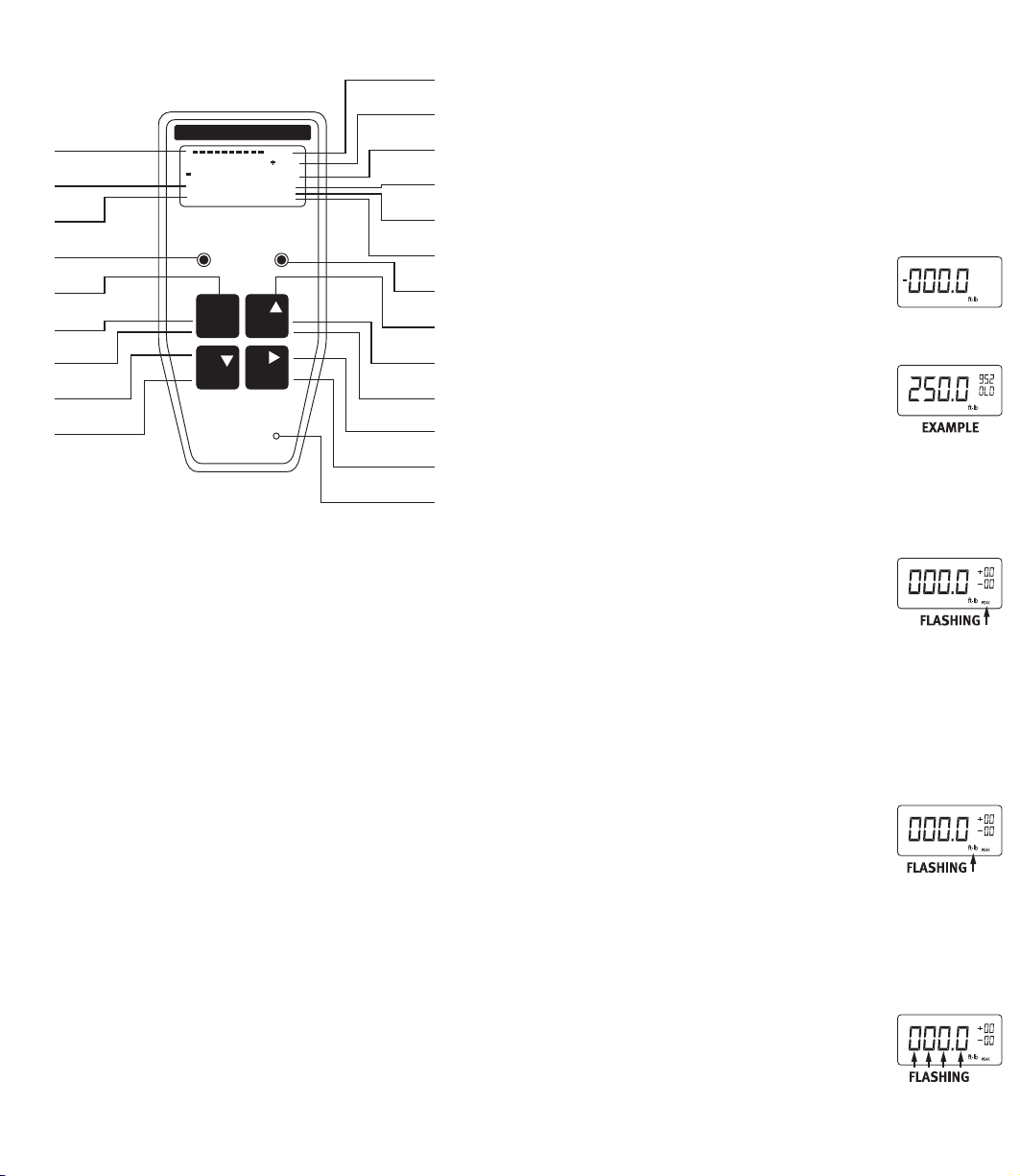
kEY PAd FUNcTIONS
000.0
000.0
171.5
000.0
171.5
000.0
171.5
000.0
171.5
ANALOG BAR GRAPH
A
SUPER TWIST LIQUID CRYSTAL DISPLAY
B
7 TORQUE UNITS (Ft.Lb., In.Lb., In.Oz., Nm, dNm,
C
MKG, CmKG
GREEN “GO” LIMIT LED
D
POWER ON/OFF
E
CLEAR LCD DISPLAY
F
ZERO TARE
G
ENTER (ACCEPT INFORMATION)
H
RECALL TORQUE DATA STORED IN MEMORY
I
OVER TORQUE “WARNING”
J
SPECIFIC TORQUE NUMBER IN MEMORY BEING
K
RECALLED AND SHOWN ON LCD
NUMBER OF TORQUE VALUES IN MEMORY
L
LOW BATTERY INDICATION
M
TRACK MODE
N
PEAK HOLD MODE
O
RED “OVER TORQUE” LIMIT LED
P
SCROLL UP (INCREASE VALUE DURING SET-UP)
Q
STORE DATA TO WRENCH
R
SEND DATA TO COMPUTER/DATA LOGGER/
S
PRINTER
SHIFT TO NEXT FLASHING DIGIT (DURING SET-UP)
T
SET-UP PARAMETERS
U
(TOLERANCE LIMIT/TORQUE UNIT)
AUDIO BUZZER
V
OPERATING INSTRUcTIONS
Please Note: There is an “off-on” slide switch located on
the right side of the wrench The wrench is shipped from
the factoiy with the switch in the “off” position. Before
use, slide the switch up or “on” Place the switch in the
“off” position only if the wrench is to be stored or not
used for a period of time. Otherwise, leave the switch in
the “on” position.
ELECTRONIC WRENCH SETUP
• TO TURN WRENCH “ON”
Press Button #1 (on/off).
Slide battery selector switch “Up” (on) or press Button
#1 (on/off) if slide switch is already in
the “Up” position.
The red and green lights will flash.
Zeros will flash and then be displayed on
the LCD along with the unit of torque measure.
The wrench is ready to use.
NOTE: If button #1 is pressed and held when first
turning the wrench “on”, the torque range capacity
and current software version of program will be
displayed. When first turning the wrench
on (sliding the switch “up”), the LCD will
ash “data good” then ash all zeros.
• TO CHANGE MODE OF OPERATION: “TRACK” OR
“PEAK”
1. Press Button #4 (set-up) one time.
Either “Track” or “Peak” will be ashing.
2. To change the mode, press Button #2 (store/send).
Continued pressing of Button #2 (store/send) will
toggle between “Track” and “Peak”
3. Press Button #3 (recall) to accept the
desired “ashing” mode change into
wrench memory.
• TO CHANGE UNIT OF TORQUE MEASURE: In.lb., In.oz.,
NM, dNM, MKG, CmKG, ft.lb.
1. Press Button #4 (set-up) two times.
The unit of measure will flash on the display.
2. To change the unit of measure, press
Button #2 (store/send). Continue
pressing Button #2 (store/send) until
the unit of measure desired is blinking
on the LCD.
3. Press Button #3 (recall) to accept this change into the
wrench memory.
Page 4
OPERATING INSTRUcTIONS
000.0
171.5
000.0
171.5
000.0
171.5
171.5
• TO SET A TARGET TORQUE VALUE:
1. Press Button #4 (set-up) three times.
The rst zero (0) on the digital display will blink.
2. To set a nominal target value into wrench memory,
press Button #2 (store/send). As this button is
repeatedly pressed, numbers zero through nine (0-9)
will be displayed.
3. When the correct number is displayed on the first
digit, press Button #4 (setup). This will “hold” that
number and cause the second digit to blink.
4. Again, press button #2 (store/send) until the value
desired is displayed (0-9).
5. Press Button #4 (set-up) to “hold” this value and
cause the third digit to blink.
6. Continue the same steps above to set the values for
the third and fourth digits.
7. After pressing Button #4 (set-up) on the last digit, the
decimal point will be blinking. This “point” can be
placed in three different locations by pressing Button
#2 (store/send). Press Button #4 (set-up) when the
decimal point is in the desired location.
• TO SET PERCENTAGES OF TOLERANCES:
1. Press Button #4 (set up), until the rst
digit of two in the upper right corner is
blinking.
2. This will be the rst of two digits in the (+) maximum
tolerance percentage. Again, as before, press Button
#2 (store/send) until the rst digit is set at the
FlASHING desired value. Press Button #4 (set-up)
to accept this value and move to the next blinking
number.
3. Repeat the above procedure for the
second digit. When the desired digit is
displayed, press Button #4 (set-up). The
maximum tolerance is now entered.
4. The rst digit of the (-) minimum tolerance should
be ashing. Press Button #2 (store/send) to scroll
through numbers (0-9). Press Button #4 (set-up) to
accept this value and move to the second flashing
digit. Press Button #2 (store/send) to scroll through
numbers (0-9) until the second desired number is
displayed.
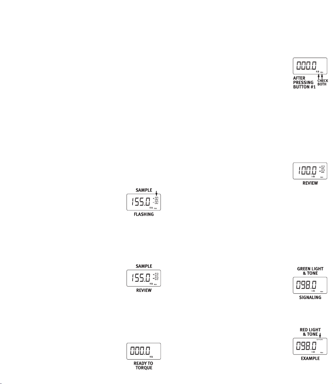
NOTE: Review the entire LCD at this time.
If everything is as desired, press Button #3
OPERATING INSTRUcTIONS
(recall) to accept all parameters into wrench memory.
These parameters will remain in memory until they are
changed.
EXAMPLE SET-UP
To set a 250 in.lb. Computorq II to a
nominal “target” value of 100 in.lbs. +/-2%
the following steps would be necessary:
1. Press Button #1 to turn the wrench “on”
( check to see if “peak” is active
2. Press Button #4 twice and verify if the active torque
units are in in. lbs.
3. Press Button #4 one more time to activate the rst
blinking “0”.
4. Press Button #2 until the number “1” is displayed.
5. Press Button #4 ve times to scroll through the three
remaining zeros and the decimal point placement.
6. Press Button # 4 one more time to scroll through
the rst zero of the (+) maximum
percentage. The second digit should be
blinking.
7. Press Button #2 until the number “2” is
displayed on the second digit.
8. Press Button #4 twice to the second digit of the (-)
minimum percentage.
9. Press Button #2 until the number ‘2” is displayed on
the second digit.
* Review Entire LCD at this time.
10. Press Button #3 to place all above parameters into
memory of wrench.
PLEASE NOTE: The wrench will sound an audible signal
and a green light will flash when the
applied torque to the wrench reaches the
lower acceptable torque limit of 98 in.lbs.
(100 in.lbs. - 2%). The green light and
audible tone will continue until the torque
value reaches the maximum preset limit of 102 in.lbs.
(100 in.lbs. RED LIGHT + 2%). The red & green lights
will ash and intermittent tones will sound if the &
TONE torque value exceeds the maximum
percentage allowed. Loud audible tones
and flashing lights will continue even
when an over torque (of the range of the
wrench) condition occurs. The display
will then show “OVER” in small letters in the extreme
Page 5

OPERATING INSTRUcTIONS
000.0
000.0
171.5
000.0
171.5
000.0
171.5
000.0
171.5
000.0
171.5
000.0
171.5
000.0
171.5
171.5
EXAMPLE upper right of the display. After
a over torque of 15% of the range of the
wrench, ‘OvEr” will be displayed on the
LCD. Damage may have already occurred.
ELECTRONIC WRENCH FUNCTIONS
• TO USE IN “TRACK” MODE OF OPERATION:
1. Turn wrench “on”. Check to see if wrench is in
“TRACK” mode
2. Place wrench on a fastener and apply a
force. The value on the LCD will rise with
the applied torque and then decrease when this force
is removed. Thus, the values will “track-up” and then
“track down”.
• TO USE IN “PEAK” MODE OF OPERATION:
1. Turn wrench “on”.
2. Refer to section “TO CHANGE MODE OF
OPERATION” if wrench is not in “PEAK”
mode.
3. Apply a force with the wrench, the
highest torque value will be held on the LCD.
• TO USE MEMORY FEATURE IN PEAK MODE OF
OPERATION:
1. Set up wrench to “Peak” mode of operation.
2. Load the wrench to correct applied torque desired.
Release the force applied. The maximum torque
(peak) will remain on the display.
NOTE: YOU NOW HAVE TWO OPTIONS
A. Press Button #2 (store/send) to store
this torque value into memory. The
display will clear to all zeros (000.0). The
number “001” will appear in the lower
right of the display. Repeat step 2 above
and then press Button #2 (store/send)
until the desired number of applied
torque values is reached.
B. Press Button #1 (clear/zero) and LCD will
clear...wrench is ready for new torque operation. No
value is stored in memory.
• TO RECALL DATA STORED IN MEMORY TO THE LCD:
1. Press Button #3 (recall). The torque values placed
in memory will appear on the digital display in the
OPERATING INSTRUcTIONS
reverse order that they were placed in
memory. Example: Last torque value
taken and placed into memory is first to
be recalled. The sequence number will
be displayed in the upper right of the
AFTER display (just above the total number of stored
torque values in memory).
2. Continued pressing of Button #3 (recall)
will scroll through all torque values in
memory.
• TO DOWNLOAD THE STORED DATA TO A
PRINTER OR COMPUTER:
Connect proper cable from printer, datalogger or
computer to wrench.
1. Press Button #3 (recall) at any time
during the torque sequence (see
above).
2. Then press Button #2 (store/send). The display will
show the values are being MEMORY
sent by indicating “SEnd” on the LCD
and will signal when all the data has
finished being transmitted by a audible
tone and the LCD display returning to the last torque
value left on the display.
3. If, after a single torque value has been taken, and you
wish to “send” this value to a peripheral, press and
hold Button #2 (store/send) for approx. 2 seconds.
A tone indicates completion of this function. If this
torque value also needs to be placed into memory,
press button #2 (store/send) once.
PLEASE NOTE: When downloading recalled memory to a
printer or computer, the data will be sent
and printed in the order torque values
were taken. Example: First value taken will
be first value printed.
* Please refer “INTERFACE CABLES”
section for proper cabling and “CALIBRATION
PROCEDURES” section for factory set parameters.
** If “Err” is displayed on the LCD during transmission
of torque data, the battery may need to be replaced.
Refer to the “BATTERIES” section for battery
replacement diagrams.
Page 6

OPERATING INSTRUcTIONS
ft-lb
PEAK
000.0
AFTER
PRESSING
BUTTON #1 TWICE
OPERATING INSTRUcTIONS
OPTIONS
A. After data is sent, or TO CLEAR MEMORY
ANYTIME, during this process press
Button #1 (clear/zero) TWICE in rapid
succession. An audible tone is sounded
indicating all stored data in memory will
be erased. The display will read “CLr”
and then all zeros.
PLEASE NOTE: Data being sent to a
printer or computer may be terminated
at any time by pressing Button # 2 (store
/ send).
B. To continue to add more values to the
existing memory, press Button #4
(set-up) and take more torque readings.
PLEASE NOTE:
A. To prevent stored torque values in memory from
being cleared erroneously, an operator must first
have recalled torque values on the LCD by pressing
Button #3 (recall) and then pressing Button #1
(clear/zero) twice.
B. While applying a load to the fastener, in “TRACK’
mode, care must be used by the operator to assure
that the applied torque is “held somewhat steady”
while Button #2 (store/send) is pressed. Computorq
II’s microprocessor will capture and store the values
on the display the instant Button #2 (store/send) is
pressed.
• TO TURN WRENCH “OFF”:
Press and hold Button #1 (clear / zero) for
approximately 2 seconds. An audible tone will signal
and the display will turn blank. If the wrench is to be
stored or not used for prolonged periods of time, slide
the ‘off-on” switch to the “off” position to conserve
battery life.
If there is a TARGET torque value with percentage
tolerances, the ten segment bar graph will show full
scale AT THE TARGET VALUE - not the wrenches’ full
scale.
EXAMPLE: 250 Ft.Lb. Wrench
set at 100 Ft.Lb. - Torquing in
Counter-Clockwise Direction
PLEASE NOTE:
A. The next time the wrench is turned “ON”, the same
parameters as last used will still be active until
changed.
B. If “Err” is displayed on the LCD (ashes at any time)
the wrench should be turned off and then on with NO
LOAD on the wrench. If “Err” continually appears on
the LCD after performing the above procedure, return
the wrench to the factory for evaluation.
IMPORTANT NOTICE: Please read all safety and
operational cautions and warnings contained in this
manual before using your electronic torque wrench
found at the beginning of this manual.
COMPUTORQ II is, in effect, a transducer. Torque
transducers are sensitive measuring instruments.
“Over Torquing” past the useable torque range of the
wrench may result in permanent damage. Always load
the wrench slowly and do not exceed the useable range
in any application.
• BAR GRAPH FUNCTION
A ten segment bar graph on the top of the LCD is a
reference for the operator of the relative position of
applied torque to the full range of the wrench. This is
whether in track or peak modes.
EXAMPLE: 250 Ft.Lb. Wrench -
Torquing in Clockwise Direction
Page 7

RS-232 cOMMUNIcATION
1
CLEAR
ZERO
STORE
SEND
2
RECALL SETUP
3 4
STORE
SEND
2
RECALL
SETUP
3
4
TRACK
ooo.o
o
TRACK
2.ooo
TRACK
ooo.o
2
2”
OFF ON
00 0 1
LINE FEED
CARRIAGE
RETURN
UNITS
BLANK
VALUE
SIGN
BLANK
SEQUENCE #
12 3 , 45 IN - LB
CR LF
+
INSTRUCTIONS LEGEND
LIGHT ON
BUZZER SOUNDS
INPUTTING THE LENGTH OF THE ADAPTOR
ACCEPTED
GO BACK TO MAIN MENU
CENTER OF SQUARE DRIVE TO
CENTER OF THE OPEN END.
BOX END OR FLARE NUT DRIVES
PRESS
PRESS + HOLD
UNITL
BUZZER SOUNDS
STORE
SEND
2
RECALL
SETUP
3
4
TRACK
ooo.o
o
TRACK
2.ooo
TRACK
ooo.o
2
2”
INSTRUCTIONS LEGEND
LIGHT ON
BUZZER SOUNDS
INPUTTING THE LENGTH OF THE ADAPTOR
ACCEPTED
GO BACK TO MAIN MENU
CENTER OF SQUARE DRIVE TO
CENTER OF THE OPEN END.
BOX END OR FLARE NUT DRIVES
PRESS
PRESS + HOLD
UNITL
BUZZER SOUNDS
1
cOMPUTORq IITM MOdELS
The Format Used for
Computorq II RS-232 Communication
ELECTRONIC WRENCH
50 & 250 In.Lb. Models • 50 Ft.Lb. Model
ELECTRONIC WRENCH
250, 600 & 1000 Ft.Lb. Models
Page 8

cALIbRATION PROcEdURES
1
o.o.o.o
cALIbRATION PROcEdURES
Due to the accuracy and the sensitivity of the
Computorq II electronic torque wrench, a mechanical
torque loader with a torque display (preferably
electronic) must be used for input torque. The loader is
necessary because the human hand cannot “push” or
“pull” on the wrench with enough stability for the torque
input to be an accurate value.
The calibration procedure must be done in both
directions (CW and CCW).
Please consider the following calibration precautions:
• Make sure the Computorq II is level (or horizontal
while in the loader. If not, side loading may affect the
true readings.
• Make sure the “reaction point” is in the center of the
grip or handle.
• Make sure the least amount of sockets and adapters
are used when mating to the calibration equipment.
• Check all sockets and adapters for “excessive play.”
This could result in false loads being applied and
shown on the display.
• Make sure the wrench is in the proper torque
engineering units prior to calibrating.
• Make sure the wrench mode of operation is in
“TRACK.” Refer to the “OPERATING INSTRUCTIONS”
section for proper setup.
* Accuracy
+/-1% From 20-100% of scale.
+/-1%, plus 5 increments, from 10-20% of scale.
Wrenches may be set up in 7 different torque
engineering units: ft. lb., in. lb., in. oz., nm, dNm,
mkg or cmkg. Refer to “TO CHANGE UNIT OF TORQUE
MEASURE” in the “OPERATING PROCDURES”.
Factory set parameters: Transmission data rate is 1200
baud; Communication protocol is RS 232 ASCII, 8
data bit, no parity. Other options are available, please
consult factory for additional information.
Please Note: Computorq II has an exclusive feature
— when using extensions or adapters, Computorq II’s
electronics can automatically compensate for these
extra lengths. Refer to the “PROCEDURES FOR USING
ADAPTERS” section.
COMPUTORQ II shown being Calibrated
on a Mechanical Loader.
SPECIFICATIONS
Product Torque Length Wt.
Code Drive Range Incr. In. Lbs.
501CI-II 1/4” 5-50 in.lb. .01 in.lb. 13.5 1.5
2502CI-II 3⁄8” 25-250 in.lb. .1 in.lb. 14.9 2.0
502CF-II 3⁄8” 5-50 ft.lbs. .01 in.lb. 14.9 2.0
2503CF-II 1⁄2” 25-250 ft. lbs. .1 in.lb. 21.5 3.2
6004CF-II 3⁄4” 60-600 ft.lbs. .2 in.lb. 46.5 9.5
10005CF-II 1” 100-1000 ft.lb. .1 ft.lb. 74.0 19.0
Page 9

cALIbRATE cW dIREcTION cALIbRATE ccW dIREcTION
RECALL SETU P
3 4
STORE
SEND
2
RECALL SETU P
3 4
STORE
SEND
2
RECALL SETU P
3 4
STORE
SEND
2
RECALL SETU P
3 4
STORE
SEND
2
RECALL SETU P
3 4
RECALL SETU P
3 4
RECALL SETU P
3 4
STORE
SEND
2
RECALL SETU P
3 4
STORE
SEND
2
RECALL SETU P
3 4
STORE
SEND
2
RECALL SETU P
3 4
STORE
SEND
2
RECALL SETU P
3 4
RECALL SETU P
3 4
1
CLEAR
ZERO
STORE
SEND
2
RECALL SET UP
3 4
RECALL SET UP
3 4
RECALL SET UP
3 4
1
CLEAR
ZERO
STORE
SEND
2
RECALL SET UP
3 4
RECALL SET UP
3 4
RECALL SET UP
3 4
FIRST: Exercise the wrench to full scale 3 times in the CW direction
before calibration sequence begins.
LCD DISPLAY LCD DISPLAY
HOLD KEY FOR 3 SECONDS (BUZZER ON) FIRST DIGIT WILL BLINK
ENTER “CALIBRATE CW” CODE 5251 BY:
A/- PRESS KEY SCROLL UP TO (5) PRESS KEY SHIFT NEXT DIGIT
B/- PRESS KEY SCROLL UP TO (2) PRESS KEY SHIFT NEXT DIGIT
C/- PRESS KEY SCROLL UP TO (5) PRESS KEY SHIFT NEXT DIGIT
D/- PRESS KEY SCROLL UP TO (1) PRESS KEY SHIFT NEXT DIGIT
E/- PRESS KEY ACCEPTED CODE 5251
BUZZER WILL TURN ON AND
LCD WILL DISPLAY
FULLY UNLOAD WRENCH AND IN
CW DIRECTION UNTIL “LOAD” ON
LCD DISAPPEARS
AND DISPLAY SHOWS (“0--0” / “-00-”)
FULLY UNLOAD WRENCH AND
WAIT 10 SECONDS, THEN PRESS KEY
LCD WILL DISPLAY “ ”
KEEP AN EYE ON THE ELECTRONIC DISPLAY
LOAD TO FIRST VALUE
PRESS KEY TO ACCEPT
THE FIRST CALIBRATION POINT,
SET BY MANUFACTURER
FIRST: Exercise the wrench to full scale 3 times in the CCW direction
before calibration sequence begins.
HOLD KEY FOR 3 SECONDS (BUZZER ON) FIRST DIGIT WILL BLINK
ENTER “CALIBRATE CCW” CODE 5252 BY:
A/- PRESS KEY SCROLL UP TO (5) PRESS KEY SHIFT NEXT DIGIT
B/- PRESS KEY SCROLL UP TO (2) PRESS KEY SHIFT NEXT DIGIT
C/- PRESS KEY SCROLL UP TO (5) PRESS KEY SHIFT NEXT DIGIT
D/- PRESS KEY SCROLL UP TO (2) PRESS KEY SHIFT NEXT DIGIT
E/- PRESS KEY ACCEPTED CODE 5252
BUZZER WILL TURN ON AND
LCD WILL DISPLAY
FULLY UNLOAD WRENCH AND IN
CW DIRECTION UNTIL “LOAD” ON
LCD DISAPPEARS
AND DISPLAY SHOWS (“0--0” / “-00-”)
FULLY UNLOAD WRENCH AND
WAIT 10 SECONDS, THEN PRESS KEY
LCD WILL DISPLAY “ ”
KEEP AN EYE ON THE ELECTRONIC DISPLAY
LOAD TO FIRST VALUE
PRESS KEY TO ACCEPT
THE FIRST CALIBRATION POINT,
SET BY MANUFACTURER
BUZZER WILL TURN OFF AND ON 10 TIMES
LCD DISPLAY WILL COUNT DOWN
FROM 10 TO 0, AND DISPLAY “ ”
NOTE: DURING PROCESS, HOLD THE
WRENCH VERY STILL UNTIL “ ” IS DISPLAYED
LCD WILL DISPLAY “ ”
KEEP AN EYE ON THE ELECTRONIC DISPLAY
LOAD TO SECOND VALUE
PRESS KEY TO ACCEPT
THE SECOND CALIBRATION POINT,
SET BY MANUFACTURER
BUZZER WILL TURN OFF AND ON 10 TIMES
LCD DISPLAY WILL COUNT DOWN
FROM 10 TO 0, AND DISPLAY “ ”
NOTE: DURING PROCESS, HOLD THE
WRENCH VERY STILL UNTIL “ ”
IS DISPLAYED
NOTE: Follow the above directions as closely as possible. Please
be careful to “LOAD” the wrench ONLY during the indicated times -
overtorquing past the range of the wrench is very possible and could
cause damage without audio/visual indicators being active during
calibration.
NOTE: When “OK” is displayed after the second calibration check
point has been checked/adjusted, the LCD should then show the
torque presently being applied.
BUZZER WILL TURN OFF AND ON 10 TIMES
LCD DISPLAY WILL COUNT DOWN
FROM 10 TO 0, AND DISPLAY “ ”
NOTE: DURING PROCESS, HOLD THE
WRENCH VERY STILL UNTIL “ ” IS DISPLAYED
LCD WILL DISPLAY “ ”
KEEP AN EYE ON THE ELECTRONIC DISPLAY
LOAD TO SECOND VALUE
PRESS KEY TO ACCEPT
THE SECOND CALIBRATION POINT,
SET BY MANUFACTURER
BUZZER WILL TURN OFF AND ON 10 TIMES
LCD DISPLAY WILL COUNT DOWN
FROM 10 TO 0, AND DISPLAY “ ”
NOTE: DURING PROCESS, HOLD THE
WRENCH VERY STILL UNTIL “ ”
IS DISPLAYED
NOTE: Follow the above directions as closely as possible. Please
be careful to “LOAD” the wrench ONLY during the indicated times -
overtorquing past the range of the wrench is very possible and could
cause damage without audio/visual indicators being active during
calibration.
NOTE: When “OK” is displayed after the second calibration check
point has been checked/adjusted, the LCD should then show the
torque presently being applied.
Page 10

1
CLEAR
ZERO
RECALL SETUP
STORE
SEND
2
34
6.00’
6.00’
6.00’
o.o.o.o
OFF ON
E
F
G
H
I
P
Q
R
S
T
U
V
o.o.o.o
1
CLEAR
ZERO
STORE
SEND
2
RECALL SETUP
3 4
OFF ON
1
CLEAR
ZERO
STORE
SEND
2
RECALL SETUP
3 4
STORE
SEND
2
RECALL
SETUP
3
4
TRACK
ooo.o
o
TRACK
2.ooo
TRACK
ooo.o
2
2”
OFF ON
00 01
LINE FEED
CARRIAGE
RETURN
UNITS
BLANK
VALUE
SIGN
BLANK
SEQUENCE #
12 3 , 45 IN- LB
CR LF
+
INSTRUCTIONS LEGEND
LIGHT ON
BUZZER SOUNDS
INPUTTING THE LENGTH OF THE ADAPTOR
ACCEPTED
GO BACK TO MAIN MENU
CENTER OF SQUARE DRIVE TO
CENTER OF THE OPEN END.
BOX END OR FLARE NUT DRIVES
PRESS
PRESS + HOLD
UNITL
BUZZER SOUNDS
FEATURES INTERFAcE cAbLES
COMPUTORQ II TO
MITUTOYO PRINTER
COMPUTORQ II TO
SERIAL PRINTER (RS-232)
COMPUTORQ II
TO PC
COMPUTORQ II shown Connected
to Data Logger Interface.
6 PIN MALE
PLUG CONNECTOR
PLUG CONNECTOR
6 PIN MALE
6 PIN MALE
PLUG CONNECTOR
COMPUTORQ II features a Battery Conservation Switch
to Battery Life when the Wrench is not in use.
10 PIN FEMALE
CONNECTOR
25 PIN FEMALE
CONNECTOR
9 PIN FEMALE
CONNECTOR
Page 11

bATTERIES
STORE
SEND
2
RECALL
SETUP
3
4
TRACK
ooo.o
o
TRACK
2.ooo
TRACK
ooo.o
2
2”
BATTERY
BATTERY
LINE FEED
CARRIAGE
RETURN
UNITS
BLANK
VALUE
SIGN
BLANK
SEQUENCE #
123 ,45 IN-LB
CR LF
+
INSTRUCTIONS LEGEND
LIGHT ON
BUZZER SOUNDS
INPUTTING THE LENGTH OF THE ADAPTOR
ACCEPTED
GO BACK TO MAIN MENU
CENTER OF SQUARE DRIVE TO
CENTER OF THE OPEN END.
BOX END OR FLARE NUT DRIVES
PRESS
PRESS + HOLD
UNITL
BUZZER SOUNDS
cERTIFIcATION
REPLACEMENT LOCATION AND USE
A 9-volt alkaline battery is standard and provides
for approximately 60 hours of operation. A “LO-BAT”
indication on the display signals for replacement. There
are 10 -20 hours of wrench operation remaining, even
after “LO-BAT” is displayed. Batteries can be changed in
less than one minute.
PLEASE NOTE:
1. Have new and fresh batteries ready to install prior to
battery replacement.
2. A ashing “LO-BAT” indicates battery failure is
imminent. There are approximately 2 - 3 hours of
battery life remaining.
This torque wrench as calibrated at the factory, is
certified to meet the current ASME specification.
Additionally, all wrenches are calibrated on a torque
standard traceable to the National Institute of
Standards and Technology (N.I.S.T.).
To Convert Multiply
cONVERSION TAbLE
From To By
in. oz. in. lb. 0.06250
in. lb. in. oz. 16
in. lb. ft. lb. 0.08333
in. lb. cmkg 1.15212
in. lb. mkg 0.01152
in. lb. Nm 0.11298
in. lb. dNm 1.12984
ft. lb. in. lb. 12
50 & 250 In.Lb. Models
50 Ft.Lb. Model
250 & 1000 Ft.Lb. Models
ft. lb. mkg 0.13825
ft. lb. Nm 1.35581
dNm in. lb. 0.88507
dNm Nm 0.1
Nm dNm 10
Nm cmkg 10.1971
Nm mkg 0.10197
Nm in. lb. 8.85074
Nm ft. lb. 0.73756
cmkg in. lb. 0.86796
cmkg Nm 0.09806
mkg in. lb. 86.7961
mkg ft. lb. 7.23301
mkg Nm 9.80665
Page 12

NOTES
 Loading...