

CD 246621 User Manual
globalindustrial.ca
Distribucion Industrial Globales S DE RL DE CF
Assembly Instructions Instrucciones de Ensamblaje Directives d’assemblage
Customer Service
US: 888-628-3466
30" Variable Speed Exhaust Fan
Servicio de atención al Cliente
México: 01.800.681.6940
Service à la clientèle
Canada: 888-645-2986
MODELS
Fan With
Shutter
294498A
Fan
246621
READ & SAVE THESE INSTRUCTIONS
WARNING
• TO REDUCE THE RISK OF FIRE,
ELECTRIC SHOCK, OR INJURY TO
PERSONS, OBSERVE THE FOLLOWING:
• This product contains chemicals which are
known to the state of California to cause
birth defects or other reproductive harm.
• This exhaust fan is not for use in explosive
or combustible atmospheres.
• Read and follow all instructions before
operating fan.
• Do not use fan if any part is damaged or missing.
• Do not alter the fan’s assembly.
• All electrical connections should be made
by a qualified electrician. Installation
work and electrical wiring must be done
by qualified person(s) following all local
electrical and safety codes in the United
States and Canada, as well as the National
electrical Code (NEC) and the Occupational
Safety and Health Act (OSHA) in the United
States, and the Canadian Electric Code
(CEC) in Canada.
• Use OSHA approved lock-out tag-out
devices on power supply to prevent shock
and/or electrocution.
• When cutting or drilling into wall or ceiling,
do not damage electrical wiring and other
hidden utilities.
• To reduce the risk of fire or electrical
shock, do not expose to water or rain.
• To reduce the risk of fire or electrical
shock, do not use this fan with any solid
state speed control device.
• To reduce the risk of fire or electrical shock,
do not use an extension cord, unit is intended
to be permanently hard wired to properly
rated electrical service outlet (120V 60Hz)
• To reduce the risk of injury to persons,
install fan at least 7 feet (2.1m) above the
floor (8 feet in Canada).
• The fan frame and motor must be
electrically grounded to a suitable electrical
ground, such as a grounded water pipe or
ground wire system.
• This has a single speed motor which is
equipped with a thermo – protector and
will automatically de-energize the fan if it
overheats for any reason.
1
RULES FOR SAFE OPERATION:
1. Never insert fingers or any other objects
through the grill guard when fan is in
operation.
2. Install in interior wall. Not for use in
kitchens.
3. Disconnect the fan from its power source
when removing guards for cleaning.
4. Do not use the fan in windows. Rain and
moisture may create electrical hazard.
5. Do not place the fan near an open flame,
cooking or heating appliance, or hot
surface.
6. This fan is for indoor dry applications.
7. This fan should not be operated outside.
8. For proper exhaust operation, a window,
door, or louver should be opened on the
opposite side of the area to be ventilated.
9. Periodically clean the propeller, guard,
motor, and louver of any accumulated dirt.
033015
30 Inch Variable Speed Exhaust Fan_03-26-15.indd 1 4/8/2015 12:56:39 PM

1-800-645-2986
30" Variable Speed Exhaust Fan
SHUTTER INSTALLATION
INSTRUCTIONS
1. The unit has to be securely mounted in
a rigid framework. See chart below for
the recommended wall hole sizes.
Mounting hardware is not included.
Assembly Instructions
C Max
(Open Louver)
A
31/2"
E
D
Use appropriate hardware for wall
condition.
Model Size Recommended rough in hole size
294498A 30" 31" square hole
Model Diameter A B C Max. D E
294498A 30" 33" 30" 6" 3" 81/2"
B
B
1/4" x 1/2" Slot
(Open Louver)
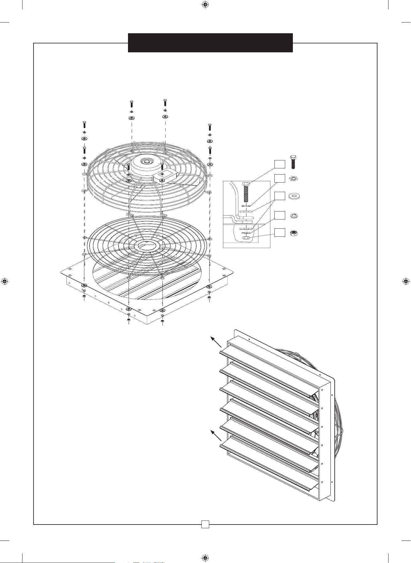
2. Remove screws, washers and nuts from
the protective screen of the fan.
2
30 Inch Variable Speed Exhaust Fan_03-26-15.indd 2 4/8/2015 12:56:40 PM
1-800-645-2986
30" Variable Speed Exhaust Fan
3. Use bolts, washers and nuts to assemble motor/fan-guard to
inner fan guard to louver-assembly.-
Assembly Instructions
HARDWARE
TOP
H1
H2
H3
H4
H5
M6 x 1.0 x 24mm
Hex Head Bolt
Star Washer
Plain Washer
Split Washer
M6 x 1.0 Hex Nut
Be sure when mounted
that the louver blades
will open upward.
BOTTOM
3
30 Inch Variable Speed Exhaust Fan_03-26-15.indd 3 4/8/2015 12:56:43 PM
1-800-645-2986
Assembly Instructions
30" Variable Speed Exhaust Fan
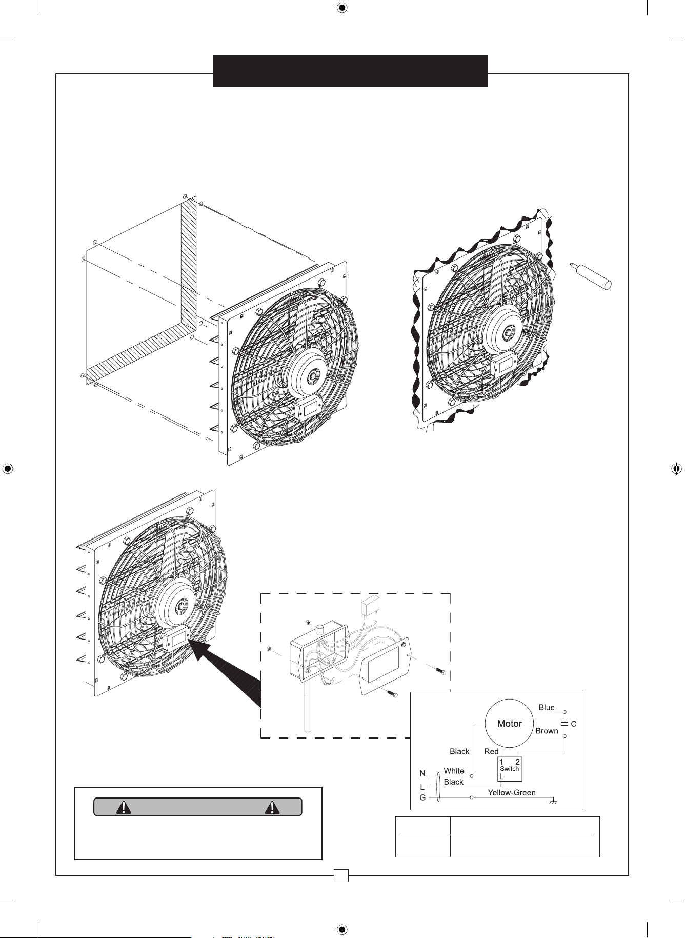
4. Use appropriate screws for framework and wall conditions.
To mount louver assembly, use the eight pre-punched
1/4" x 1/2" slotted mounting holes of the louver assembly
to attach the unit to the framework.
5. Seal the joint between the
wall and the louver with
silicon or any other sealer.
FAN INSTALLATION INSTRUCTIONS
6. Connect power to the motor, using the appropriate wiring
method. Place all connections inside junction box.
Junction Box
Wiring
Diagram
Red
WARNING
This product contains chemicals which are
known to the state of California to cause birth
defects or other reproductive harm.
4
30 Inch Variable Speed Exhaust Fan_03-26-15.indd 4 4/8/2015 12:56:45 PM
Model Rating (120V 60Hz)
246621 275W, 2.9A
 Loading...