

Page 1
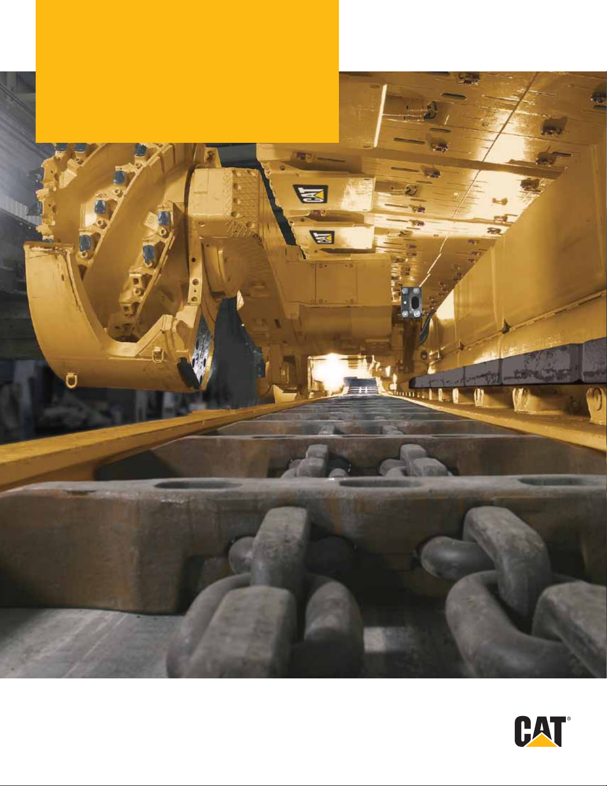
AFC Systems
High-Capacity
Page 2
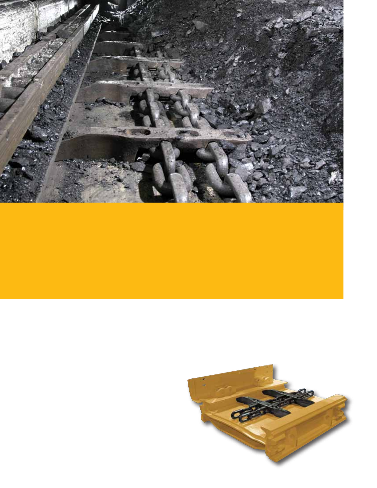
Moving Mountains
No matter how fast your shearer can cut, you can’t keep cutting until you move the coal away from the face.
Cat® Armored Face Conveyors (AFCs) are designed to keep things moving and to carry the maximum possible
amount of coal smoothly away from the coalface. They are designed for high availability and economy in
operation. They are easy to maintain and offer long service life and a great return on investment to mine
operators.
Best in the Long Run
Cat AFCs excel through cutting-edge technology, quality,
experience and superior product support. Of course,
that’s what any AFC manufacturer would like to promise.
But we can. Our engineers invented the AFC in the early
1940s. Of the ten most productive mines in the world,
eight use our face conveyors.
Several systems have successfully operated in 350 to
470 m (1,150 to 1,540 ft) faces producing up to 5 000
tonnes (5,512 tons) per hour and 10 million tonnes
(11 million tons) per year. Our experience and track
record are unmatched in super-long and high-capacity
face conveyors.
And of course, Caterpillar – recognized as a world-leading
developer and manufacturer of integrated longwall
systems – has a long history of engineering
2
solutions that meet the needs of mine operators.
That’s why our longwall systems have been in
service in all major coal-mining regions of the
world for decades.
PF6 line pan
Page 3
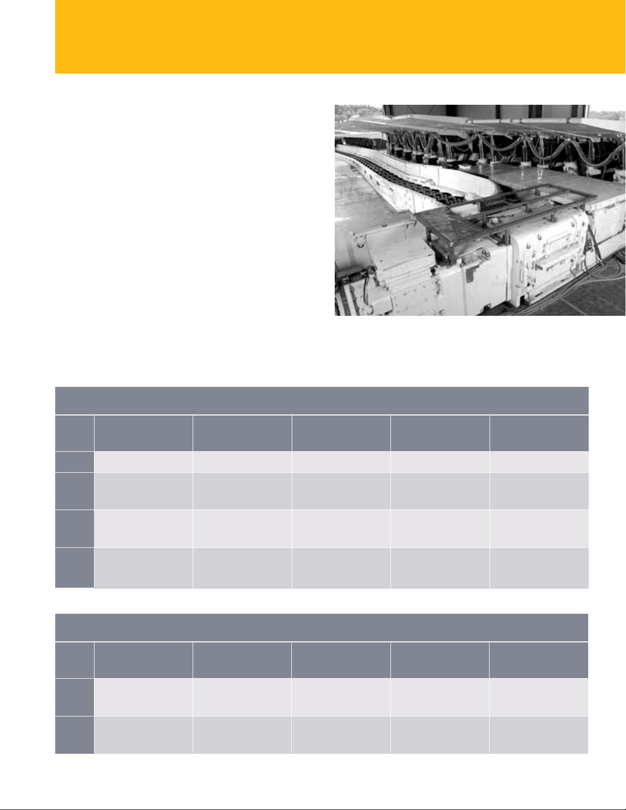
Meeting all Needs
From AFC tail drive to entry belt conveyor return end,
Cat AFC systems are designed for a variety of
performance requirements in low, medium and high
seams, for short and long faces. Caterpillar meets the
demand of today’s high-capacity shearers and, of
course, our own automated plow systems.
The PF Range
The line pan is the backbone of the AFC – literally. It not
only conveys material from the face, but also acts as the
guide rail for the shearer – with traction forces of up to
1 000 kN.
Caterpillar offers a range of line pans to suit different
needs. These range from the PF3 for capacities of up to
1 300 tonnes (1,433 tons) per hour to the state-of-the-art
PF6 with a capacity of 5 000 tonnes (5,512 tons) per hour.
Typical Technical Data AFC Line Pan
Type Width outside Top plate Bottom plate Dogbone Production
Compatibility testing of a complete Cat® longwall
thickness thickness breaking force average per hour
PF3 822 mm (32.4 in) 30 mm (1.2 in) 20 mm (0.8 in) 2 000 kN 1 300 tonnes (1,433 tons)
PF4 932 mm (36.7 in) 1 800 tonnes (1,984 tons)
PF5 1 042 mm (41.0 in) 2 500 tonnes (2,756 tons)
PF6 1 042 mm (41.0 in) 2 500 tonnes (2,756 tons)
1 032 mm (40.6 in) 40 mm (1.6 in) 25 mm (1.0 in) 3 600 kN 2 500 tonnes (2,756 tons)
1 132 mm (44.6 in) 3 500 tonnes (3,858 tons)
1 142 mm (45.0 in) 50 mm (2.0 in) 30 mm (1.2 in) 4 500 kN 3 500 tonnes (3,858 tons)
1 342 mm (52.8 in) 5 000 tonnes (5,512 tons)
1 142 mm (45.0 in) 30+25 mm (1.2+1.0 in) 30 mm (1.2 in) 4 500 kN 3 500 tonnes (3,858 tons)
1 342 mm (52.8 in) 5 000 tonnes (5,512 tons)
Typical Technical Data Stageloader Line Pan
Type Width outside Top plate Bottom plate Dogbone Production
PF4 932 mm (36.7 in) 2 000 tonnes (2,205 tons)
PF6 1 342 mm (52.8 in) 5 500 tonnes (6,063 tons)
1 132 mm (44.6 in) 40 mm (1.6 in) 25 mm (1.0 in) 3 600 kN 3 800 tonnes (4,189 tons)
1 332 mm (52.4 in) 5 500 tonnes (6,063 tons)
1 542 mm (60.7 in) 50 mm (2.0 in) 30 mm (1.2 in) 4 500 kN 6 200 tonnes (6,834 tons)
1 742 mm (68.6 in) 7 000 tonnes (7,716 tons)
thickness thickness breaking force average per hour
3
Page 4
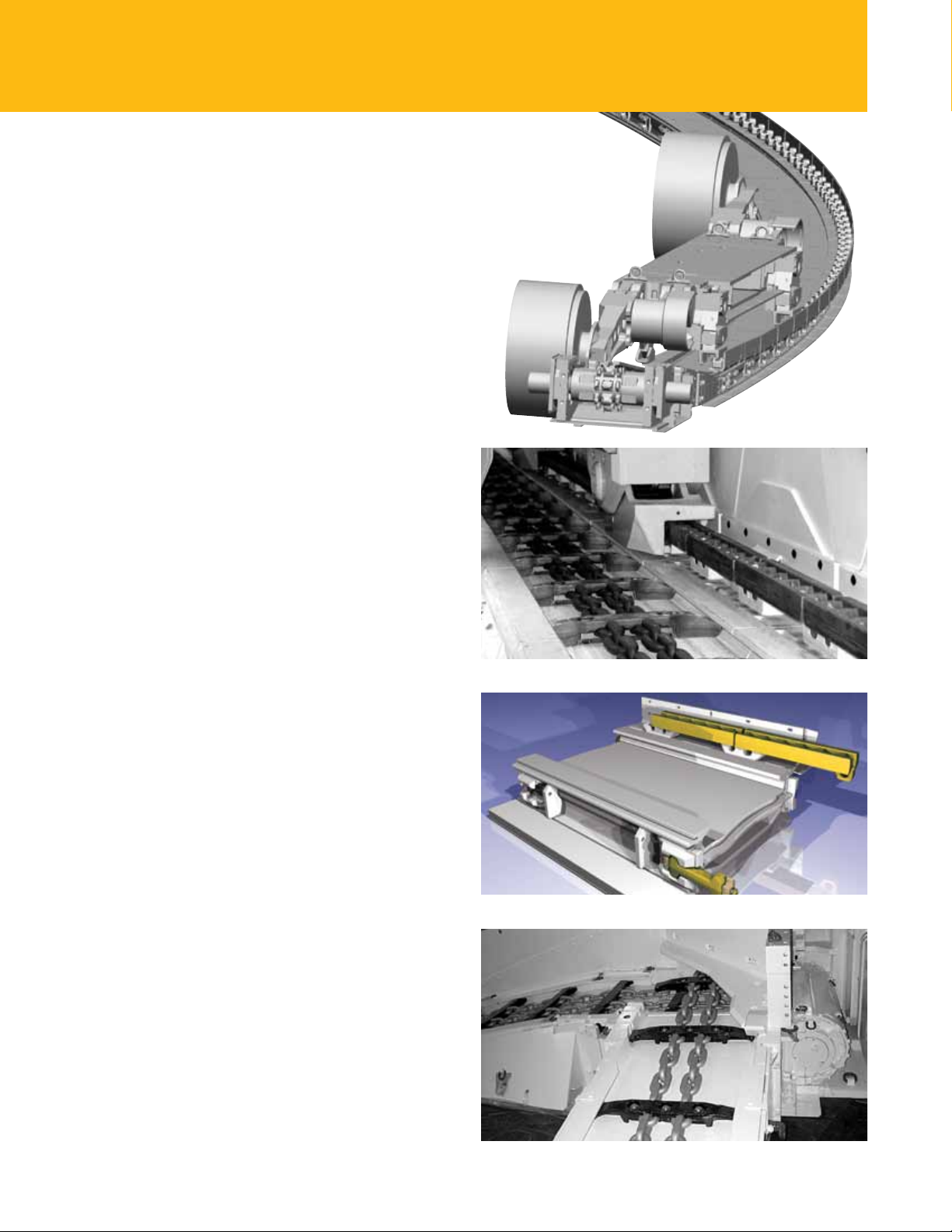
Engineered to Perfection
There are many parts to an Armored Face Conveyor:
shearer haulage system, drives, drive frames and sprockets,
gearboxes, line pans, chain conveyors as well as entry
conveyors and belt tailpieces. Each of these components
has to be engineered to perfection, but also has to work
together optimally with the other parts of the system.
Cat AFC components achieve this. Each is designed for
powerful, reliable and economical operation with low
maintenance over a long service life, promoting high
productivity and delivering a great return on investment.
Shearer Haulage System
Cat rackbar shearer haulage systems meet the demands
of today’s high-performance shearers. We use design and
material selection aimed at achieving maximum system
availability, longest possible shearer, sprocket and trapping
shoe life and on-system suitability for seam undulations.
As with all Cat products, these systems are the result
of extensive R&D work and comprehensive laboratory
and eld testing. This ensures the optimum solution for
haulage system and sprocket. This led to a unique design
concept with optimized rst/last tooth geometry rackbars
available with pitches of 126 mm for medium-production
and 146/151 mm for high-production shearers.
3D-Simulation of a shearer
on a Cat PF6 face conveyor
at the head end under
extreme bending
Jumbotrack
™
shearer haulage system
Drive Frames
Head-gate drive frames operated today are typical of the
cross-frame design. Different capacity ratings are available
depending on the total power required. The frame sides
are manufactured from thick, solid plates to handle the
high torque that may be generated and to ensure an
adequate safety margin. Flange plates used to mount the
transmission units enable easy rehanding.
Benets
• Head drive does not cause a production bottleneck,
maximum stability at maximum power, high power
drives can be installed, upgrade normally possible,
high AFC performance and availability.
Jumbotrack
Crossframe
™
shearer haulage system
4
Page 5
Drive Modules
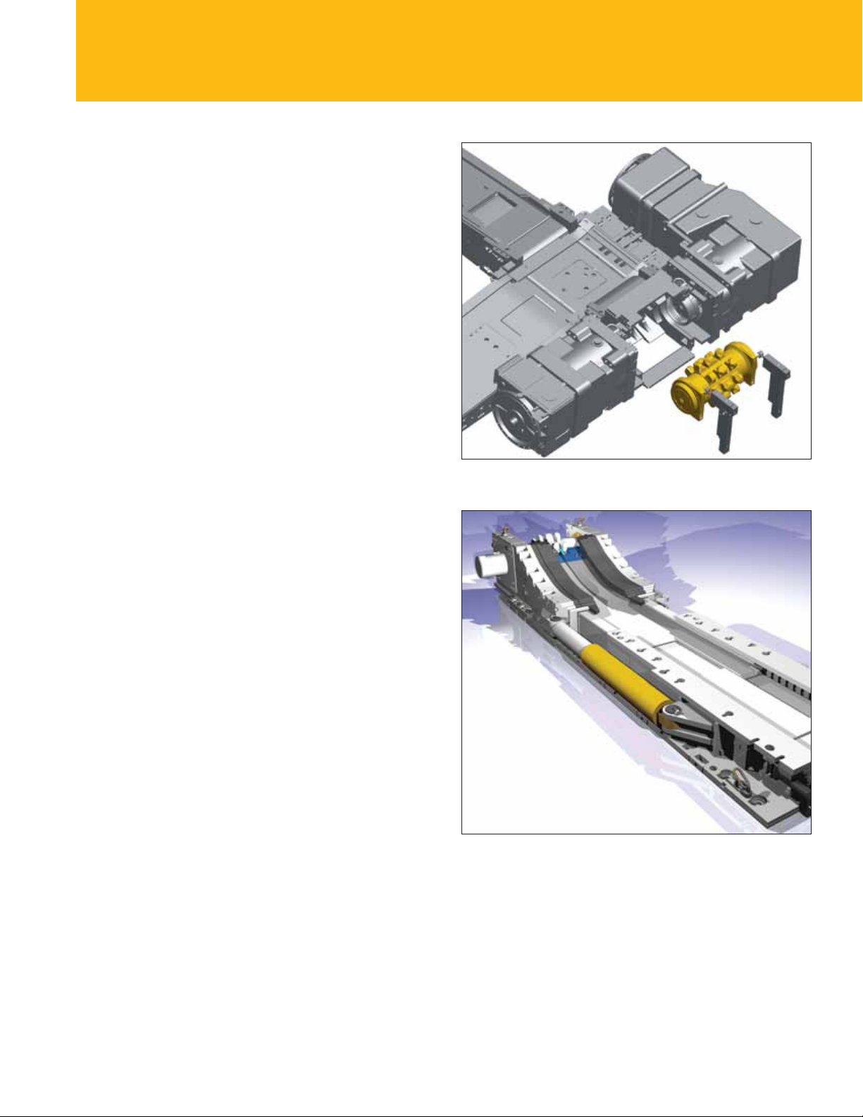
The latest development is a drive frame with replaceable
one-piece sprocket/shaft/bearing – a “drive module”.
These are available in various sizes to suit individual
power requirements, right up to 2 x 1800 kW (2,412 hp)
per drive. The drive module is identical for both main
and tail drive. The drive frames are independent of the
gearboxes used – ange plates and stub shafts are used
for interfacing. Two hydraulic cylinders are integrated in
the frames for disassembly of the drive module. These are
powered by an external pump. There are similar designs
for smaller drive frames.
Benets
• Drive module can be replaced underground without
disassembly of the gearboxes, drive units are available in
different sizes and are independent of the gearbox used.
GR Sprocket
In contrast to conventional sprockets, the Cat GR
sprocket is specially designed to spread the load across
three teeth, ensuring maximum contact surface between
the chain links and the sprocket teeth during operation.
This results in lower wear and extended life of the sprocket
and the chain.
Benets
• More efcient power transmission with GR sprocket
(97% vs. 93%), resulting in extended sprocket and chain
life and less chain stretch
Tail Drives
Tail drives are normally the tensionable type, especially
with long faces and/or high installed power. These have a
stroke of 0.50 m for shorter, less powerful conveyors, and
1 m for long faces or conveyors with extremely high
installed power. These allow control of 1 m and 2 m of
slack chain respectively. An automated system keeps the
AFC chain at optimum tension during operation.
Sprocket Module
Tensionable tail drive
Benets
• Maximum chain life and minimum conveyor downtime
for double cut
5
Page 6
Gearboxes
Caterpillar offers gearbox solutions – simple planetary or
bevel-spur gearboxes for low-power requirements and the
installation of a clutch between motor and gearbox for
medium-power installations.
The UEL gearbox – a planetary gearbox with an
integrated clutch – is designed for higher-power
requirements. This friction clutch is closed through face
support hydraulic uid. A hydraulic control system allows
the clutch to be set to a certain torque.
Overload Protection
Overload protection is achieved by measuring the slip of
each gearbox. In the event of a chain stall, both motors
are switched off. Alternatively, the clutches at both drives
can be opened using an optional drive control unit.
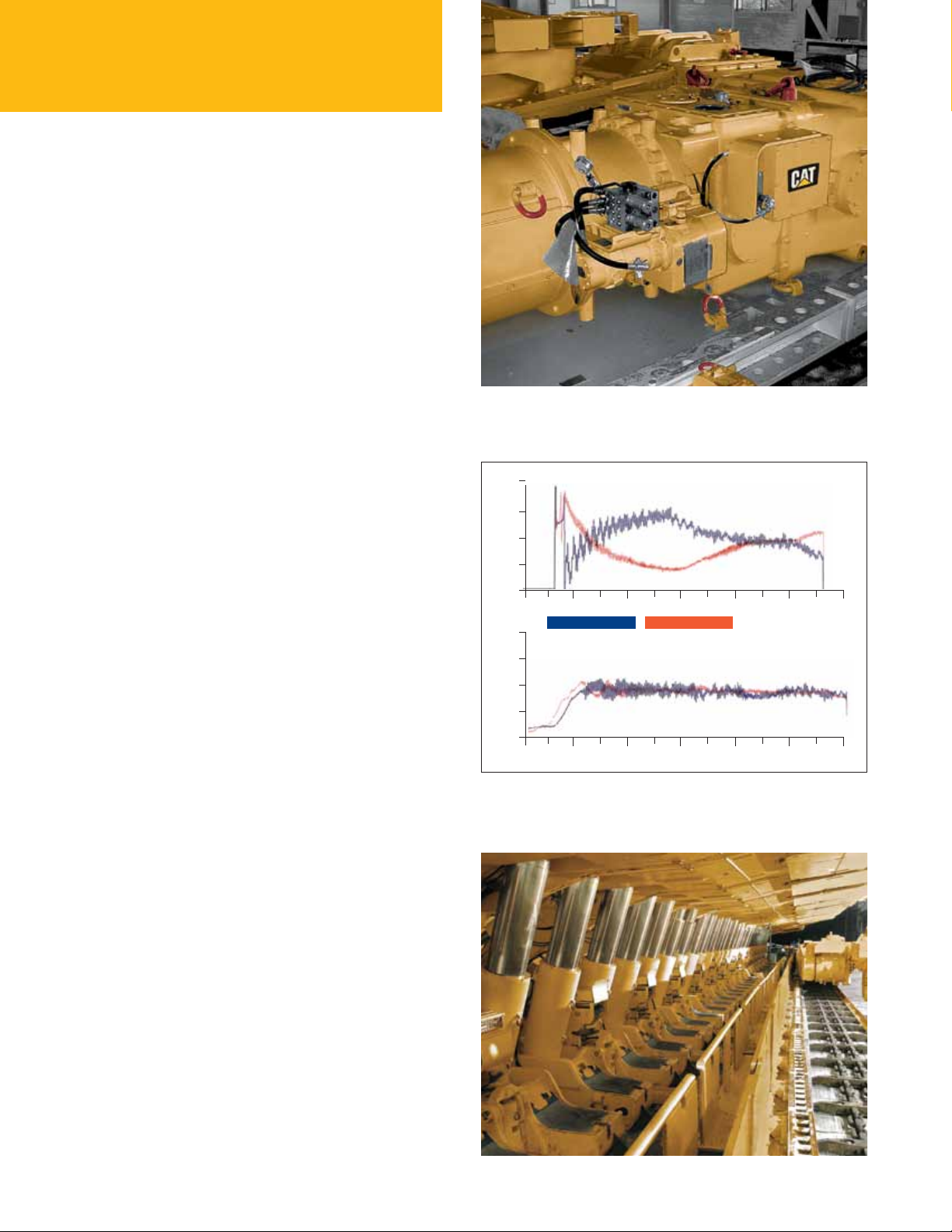
The Controlled Start Transmission (CST) drive system
is designed for long, high-capacity faces. This drive system
allows no-load motor startup, synchronized soft-start and
heavy-load startup, as well as accurate load sharing and
excellent overload protection.
Benets
• Caterpillar has the right drive for your application
ensuring smooth and safe operation of the conveyor
with overload protection and a range of other safety
features as required.
Chains
For years, we have been matching chain and
sprocket design in high-performance face conveyors
to achieve optimum performance and service life. This
resulted in the 42 x 146 mm (1.70 x 5.70 in) combination
chain, the standard chain for applications in the USA and
Australia since 1991, and later in the 48 x 144/160 mm
(1.90 x 5.70/6.30 in) chain for what was then the world’s
most powerful conveyor installation with 3 x 1000 kW
(3 x 1,341 hp) on a single longwall face conveyor. The
latest development is the Cat PowerChain. It is available
in sizes 34, 42 and 52. Size 52 is designed to be used with
up to 1 200 kW (3 x 1,608 hp), with a chain suitable for up
to 1 800 kW (3 x 2,412 hp) under development.
Cat intelligent CST drive system for highcapacity face conveyors
400
300
200
100
400
300
200
100
TD = Tail Drive HD = Head Drive
Trial run of a complete system
Load sharing capabilities
0
10 20 30 40 50 time
0
power TD (kW) power HD (kW)
0
0 10 20 30 40 50 time
without load sharing
with load sharing
6
Page 7
PowerChain
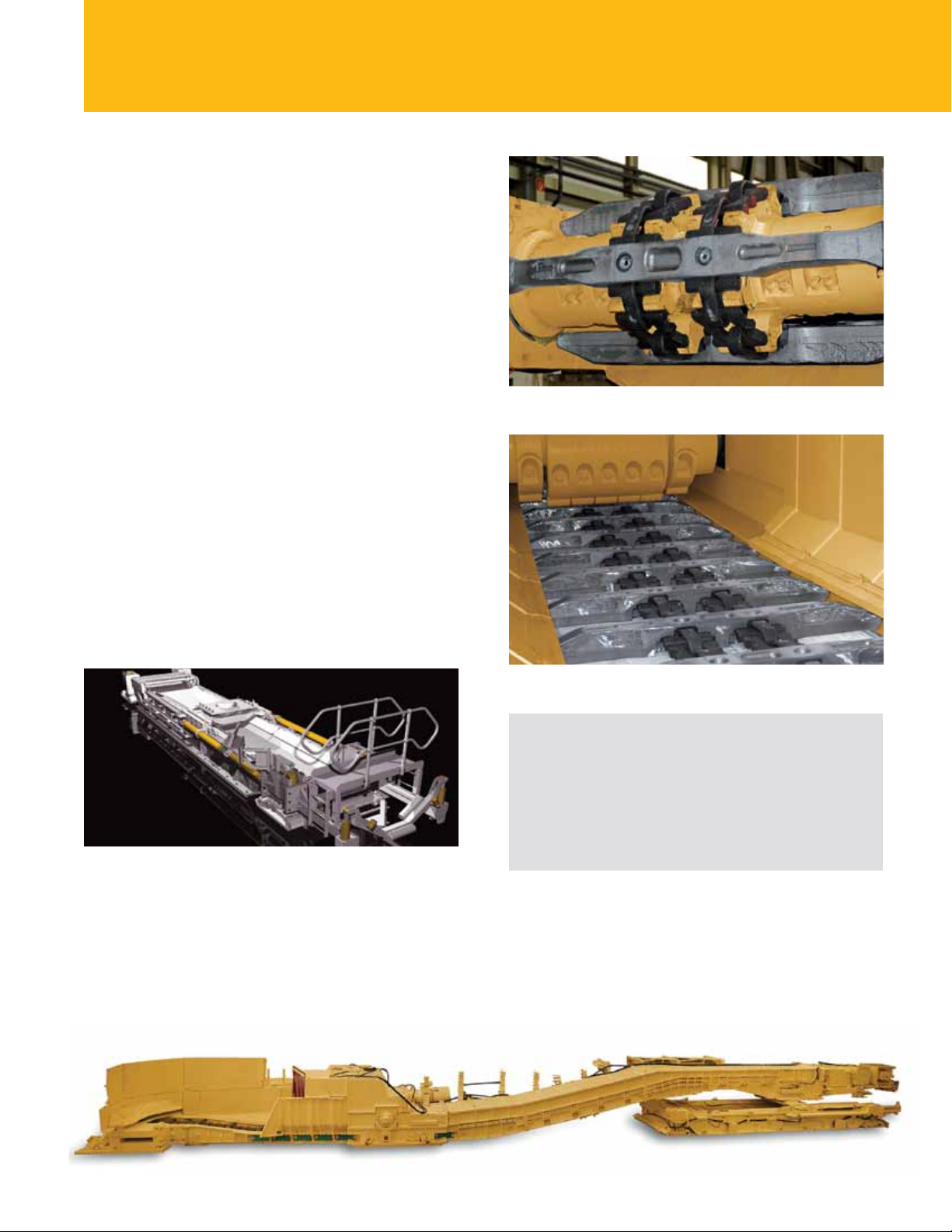
The wide, arc-shaped cross-section of the vertical links
allows a low-prole line pan and the special shape
of the horizontal link provides a large running surface
where required, drastically reducing surface pressure
and chain-joint wear. The method for attaching the
ight bar is patented.
The PowerChain 42 x 140 mm (1.7 x 5.5 in) has a breaking
force of 2 370 kN, the PowerChain 52 x 175 mm (2.0 x 6.9
in) of 3 610 kN.
Benets
• Faster removal of mined coal by providing high-
reliability, high-availability transportation with design
features ensuring low wear and long service life, greater
permissible elongation of chain compared to round link
Entry Conveyors and Belt Tailpieces
Entry conveyor or stageloader pans are normally of
the same type as used in the face. These are normally
wider than the AFC. While the return roller is integrated
into the cross frame design, the head drive frame of the
stageloader is tensionable using hydraulic cylinders.
Bootend assembly
PowerChain and sprocket in use with a Cat beam stageloader
PowerChain inside a Cat BSL in the crusher area
Benefits
Stageloader and crusher completely matched to AFC, both
with higher capacity to prevent bottlenecks; tailor-made belt
tailpiece for required capacity and belt dimensions, allowing
BTP to handle longitudinal and lateral entry gradients;
automated chain tensioning system.
The crusher, usually an impact roller, is integrated into
the stageloader design. The following goose-neck lifts
the stageloader discharge over the belt tail piece. Belt tail
pieces are available in xed-, skid- or crawler-mounted
versions with an overlap of up to 3.5 m (11.5 ft), all
equipped with self-cleaning return drums. The operator
can use any specied belt width in this tailor-made
equipment.
Complete Cat entry conveyor
or beam stage loader (BSL)
including crusher and belt tail piece
7
Page 8
Line Pans for Every Need
Rolled steel is smoother, stronger and harder-wearing
than a casting and generates less friction and noise. That’s
why Caterpillar has focused on rolled steel designs for line
pans. All aspects of the line pans have been engineered
with reliability, productivity and serviceability in mind.
Maximum Contact
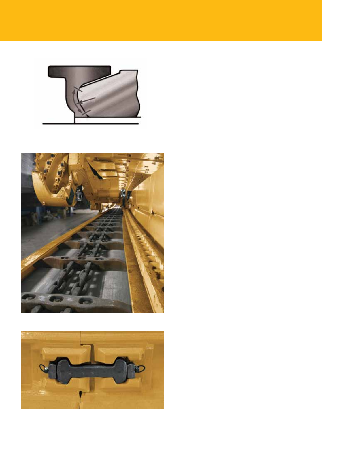
Compatibility testing
Profile shape of PF conveyors
The proles are designed to maximize the contact area
between the ight bar and the prole, thus minimizing
contact pressure during operation.
• Minimizes friction, reduces power requirements for the
face conveyor and results in longer service life of the
ights and proles
Rolled Steel
Rolled material has a smoother surface than castings.
The material shows maximum wear resistance after initial
material conveyance.
• Lower friction and longer service life for wear parts.
Up to 10 million tonnes (11 million tons) under normal
conditions and up to 20 million tonnes (22 million tons)
under favorable conditions.
Safe Dogbone Technology
The forged dogbone pocket and the designed breaking
force of up to 4 500 kN guarantee safe operation of
the conveyor at all times. Sophisticated design has been
further optimized, ensuring greater tensile strength to
reduce stress spikes and ensure perfect protection of
the dogbone pocket and the pan itself in the event of
an overload.
• Longer service life of dogbone pockets, no damage to
conveyor or dogbone housing as the dogbone always
breaks rst
Dogbone
8
Convex/Concave Pan Ends
Cat line pans feature convex/concave pan ends that
ensure reduced noise levels. Our line pans are suitable
for bi-directional operation.
Page 9
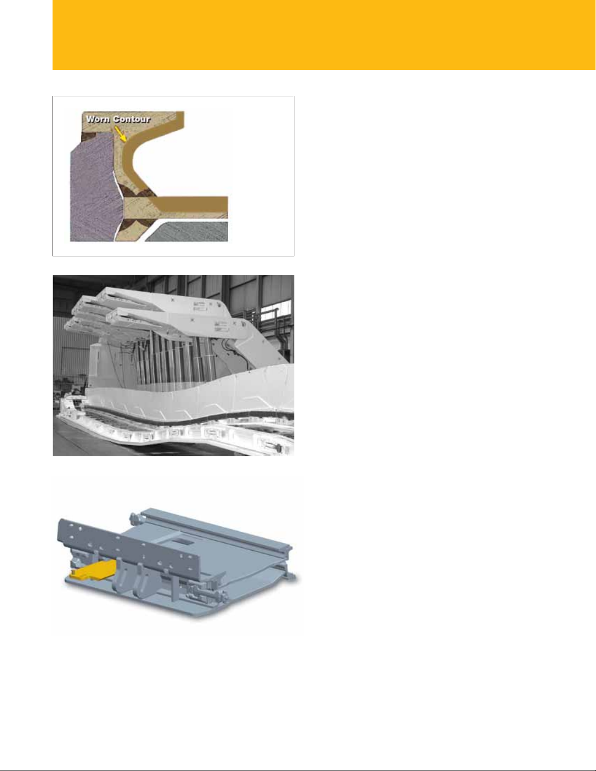
PF5 profile design
with wear pattern
Welds without Wear
Cat PF line pans have a rolled prole design. Each of the
identical proles are attached with two welds to the top
plate of chosen length and width. This results in great
exibility in pan design. Only one of the welds is located
in the wear area of the line pan in the top strand.
• High stability of the pan ensured by three welds even
when the top plate is totally worn out
Wear-resistant Top Plate
The top plate is made of wear-resistant material. The
thickness varies from 30 mm (1.2 in) (PF3) to 50 mm
(2.0 in) (PF5).
• Long service life with matched prole type end
Flexibility
The line pans are designed to allow deection between
individual line pans of ± 6° vertically and 0.8–1.2°
horizontally.
• Increased exibility, adaptation to undulating seams,
short snake sections possible
Vertical bending capability of Cat face conveyor systems
Safe Transfer of Transverse Forces
Transverse forces are transferred through the top plate to
the relay bar arrangement.
• High pan stability, even for high-reaction forces; safe
operation; low noise; minimum maintenance; full
reversibility
Inspection Doors
A sliding inspection door typically installed in every 6th
pan and every special pan allows access to the bottom
race of the chain conveyor. The integrated drawer guide
ensures safe seating of the doors. The inspection door can
be removed from gob or face side.
• Easy access to bottom chain, minimum downtime during
maintenance or repair
9
Page 10
PF6 – the State-of-the-Art Line Pan
Wear is the weak point in line pan design. Hauling
millions of tonnes of coal away from the longwall is
clearly going to result in high levels of wear. Back in
2002, we decided to try something revolutionary. A
group of experts from different countries with many years
of experience on various conveyor types was brought
together to create a new type of pan that would combine
the benets of rolled and cast line pans to provide an
optimum solution to mining industry needs.
The First to Really Last and Last
The team developed an innovative pan design meeting all
the requirements regarding quality, resistance to wear and
conveying capacity in ultra-long panels. The result is the
PF6, a hybrid pan that addresses the weakest point in pan
design: wear. The simple solution was to make the parts
subject to the most wear replaceable.
With its patented trough concept and extremely rugged
pan design, the PF6 is particularly suitable for applications
in longwalls with extended face length and
for panels with coal reserves of 10 million tonnes
(11 million tons) and up.
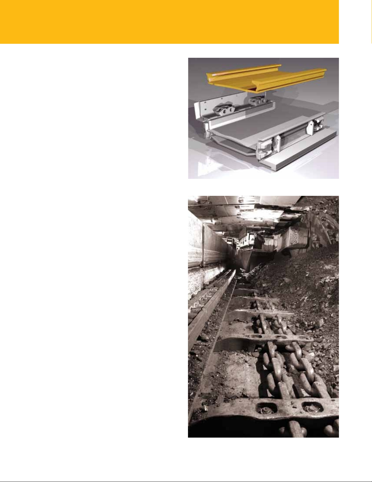
PF6 pan with replaceable top trough
Nothing Proves Success like Success
The success of the project is clear from sales: By the end
of 2011, over 15,000 PF6 line pans had been manufactured
as more and more operators become convinced of the
benets of the revolutionary PF6 concept.
Separation of Wear Parts and Structural Parts
The smart and totally new idea of splitting up the different
functional areas in the PF6 allows the separation of
wear parts and structural parts. Very hard, wear-resistant
materials are used for wear parts, while the structural parts
are made of high-strength steel.
• Ability to replace wear parts, substantially longer service
life, lower overall pan wear
10
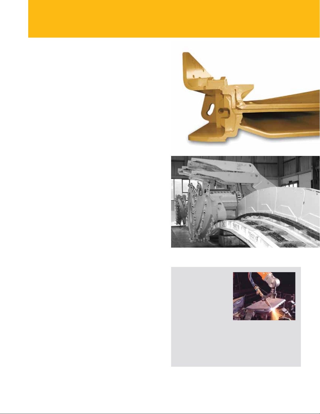
Complete Cat longwall with high-capacity AFC system
Page 11
Optimized Contact Surfaces
The special shaping of the bottom race – which almost
doubles the contact surface – reduces ightbar shoulder
wear and substantially reduces friction. The curved
transition at the pan ends greatly reduces noise during
operation of the chain conveyor.
• Minimal friction and power loss, longer ightbar and
prole service life, lower noise
Maximum Pan Stability
The frame of the pan consists of two C proles connected
by a baseplate. Two tried-and-tested PF5 proles are
welded to the bottom plate of the top trough and then
welded or bolted to the pan base. This allows problem-free
replacement of worn top troughs.
Pan sections are connected by dogbones inserted into
pockets in the C proles. These are designed to engage
exactly, providing optimal absorption of vertical
and horizontal reaction forces. This ensures reliable
transmission of high lateral forces, such as from roof
supports. All forces were calculated and the pan was
successfully tested with the frame of the PF6 pan only.
Profile of the PF6
shearer line pan
• High stability and positive force transmission, easy
maintenance, trouble-free operation in both directions
Customization
Whether the design of the cover plates or the design of
spill plates for hoses and cables, all components of the
PF6 are individually designed to meet our customers’
requirements.
• Optimal adaptation to local conditions, perfect
functioning with various shearer haulage systems
Simulation of a hump during a compatibility test with a shearer
Rolled Steel Surfaces and
Robot Welding
Extremely smooth rolledsteel surfaces ensure
minimum friction and power
loss. Robot welding ensures
standardized welds that can
be removed automatically
when the top race is
worn, allowing replacement of the trough. This innovation is
expected to increase the service life of the substructure by a
factor of 3.
• Longer service life, simple replacement of wear parts, lower
friction and power loss.
11
Page 12

High-Capacity AFC Systems �
For more complete information on Cat products, dealer services, and industry solutions,
visit us on the web at mining.cat.com and www.cat.com
© 2011 Caterpillar Inc.
All rights reserved
Materials and specifications are subject to change without notice. Featured machines in
photos may include additional equipment. See your Cat dealer for available options.
CAT, CATERPILLAR, their respective logos, “Caterpillar Yellow” and the “Power Edge” trade
dress, as well as corporate and product identity used herein, are trademarks of Caterpillar and
may not be used without permission.
AEXQ0604-01
 Loading...