

Page 1
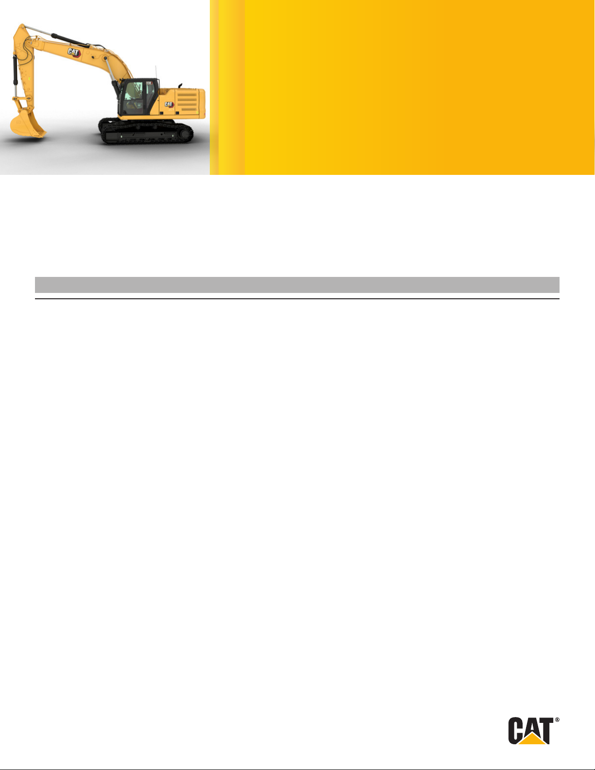
330
Hydraulic Excavator
Technical Specifications
Congurations and features may vary by region. Please consult your Cat® dealer for availability in your area.
Table of Contents
Specications ..............................................................................................2
Engine ........................................................2
Swing Mechanism .............................................2
Weights.......................................................2
Track .........................................................2
Drive .........................................................2
Hydraulic System ..............................................2
Service Refill Capacities ........................................2
Standards.....................................................2
Sound Performance . . . . . . . . . . . . . . . . . . . . . . . . . . . . . . . . . . . . . . . . . . . .2
Operating Weights and Ground Pressures.........................3
Major Component Weights ......................................3
Dimensions....................................................4
Working Ranges and Forces.....................................5
Reach Boom Lift Capacities .....................................6
Bucket Specifications and Compatibility ..........................9
Attachments Offering Guide . . . . . . . . . . . . . . . . . . . . . . . . . . . . . . . . . . . .10
Standard and Optional Equipment ...........................................................................11
Dealer Installed Kits and Attachments .......................................................................14
Page 2
330 Hydraulic Excavator Specifications
Engine
Engine Model Cat® C7.1
Net Power – ISO 9249 204 kW 273 hp
Engine Power – ISO 14396 205 kW 275 hp
Bore 105 mm 4 in
Stroke 135 mm 5 in
Displacement 7.01 L 428 in
• Meets U.S. EPA Tier 4 Final and EU Stage V emission standards.
• Recommended for use up to 4500 m (14,760 ft) altitude with
engine power derate above 3000 m (9,840 ft).
• Net power is tested per ISO 9249. Standards in effect at the time
of manufacture.
• Net power advertised is the power available at the ywheel when
the engine is equipped with fan, air intake system, exhaust system
and alternator.
• Rated speed at 2,200 rpm.
Swing Mechanism
Swing Speed 11.50 rpm
Maximum Swing Torque 110 kN·m 81,132 lbf-ft
Weights
Operating Weight – 600 mm (24")
Triple Grouser Shoes
• Long undercarriage, reach boom, R3.2 m (10'6") stick, HD 1.76m
(2.30yd) bucket, 600 mm (24") triple grouser shoes and 6700 kg
(14,770 lb) counterweight.
30 000 kg 66,000 lb
Hydraulic System
Main System – Maximum Flow –
Implement
Maximum Pressure – Equipment –
Normal
Maximum Pressure – Equipment –
Lift Mode
Maximum Pressure – Travel 35 000 kPa 5,075 psi
Maximum Pressure – Swing 29 800 kPa 4,320 psi
Boom Cylinder – Bore 140 mm 6 in
Boom Cylinder – Stroke 1407 mm 55 in
Stick Cylinder – Bore 150 mm 6 in
Stick Cylinder – Stroke 1646 mm 65 in
Bucket Cylinder – Bore 135 mm 5 in
Bucket Cylinder – Stroke 1156 mm 46 in
560 L/min
(280 ×
2pumps)
35 000 kPa 5,075 psi
38 000 kPa 5,510 psi
148 gal/min
(74 ×
2pumps)
Service Refill Capacities
Fuel Tank Capacity 474 L 125.2 gal
Cooling System 25 L 6.6 gal
Engine Oil 25 L 6.6 gal
Swing Drive 10 L 2.6 gal
Final Drive (each) 5.5 L 1.5 gal
Hydraulic System (including tank) 310 L 81.9 gal
Hydraulic Tank 147 L 38.8 gal
DEF Tank 41 L 10.8 gal
Track
Standard Track Shoes Width 600 mm 24 in
Optional Track Shoes Width 700 mm 28 in
Number of Shoes (each side) 50
Number of Track Rollers (each side) 9
Number of Carrier Rollers (each side) 2
Drive
Gradeability 35°/70%
Maximum Travel Speed 5.3 km/h 3.3 mph
Maximum Drawbar Pull 248 kN 55,753 lbf
Standards
Brakes ISO 10265:2008
Cab/ROPS ISO 12117-2:2008
FOGS (optional) ISO 10262-2:1998 Level II
Sound Performance
ISO6395:2008 (external) 103 dB(A)
ISO6396:2008 (inside cab) 70 dB(A)
• Hearing protection may be needed when operating with an open
operator station and cab (when not properly maintained or doors/
windows open) for extended periods or in a noisy environment.
2
Page 3
Operating Weights and Ground Pressures
330 Hydraulic Excavator Specifications
Base machine with 6700 kg (14,770 lb) Counterweight
andLongUndercarriage
Reach Boom + R3.2CB2 (10'6") Stick + 1.76 m (2.30yd)
HD Bucket
Reach Boom + R2.65CB2 (8'8") Stick + 1.76 m (2.30yd)
HD Bucket
All operating weights include a 90% fuel tank with 75 kg (165 lb) operator.
600 mm (24")
Triple Grouser Shoes
Weight
kg
(lb)
30 000
(66,000)
29 900
(65,800)
Ground
Pressure Weight
kPa
(psi)
57
(8.3)
57
(8.2)
600 mm (24")
Double Grouser Shoes
Ground
Pressure Weight
kg
(lb)
30 300
(66,700)
30 200
(66,500)
kPa
(psi)
58
(8.4)
57
(8.3)
700 mm (28")
HD Triple Grouser Shoes
Ground
Pressure
kg
(lb)
30 500
(67,300)
30 400
(67,100)
kPa
(psi)
50
(7.2)
50
(7.2)
Major Component Weights
kg lb
Base machine (6700 kg [14,770 lb] counterweight, upper frame, long undercarriage with HD rollers), withboom
cylinders and weight of 90% fuel tank and 75 kg (165 lb) operator included.
Track Shoes:
600 mm (24") Width, 11 mm (0.43") Thick, Triple Grouser Track Shoes 3620 7,980
600 mm (24") Width, 14.5 mm (0.57") Thick, Double Grouser Track Shoes 3960 8,730
700 mm (28") Width, 13 mm (0.51") Thick, HD Triple Grouser Track Shoes 4200 9,260
Two Boom Cylinders 490 1,080
Weight of 90% Fuel Tank and 75 kg (165 lb) Operator 460 1,010
Counterweight:
6700 kg (14,770 lb) Counterweight 6700 14,770
Undercarriage:
Long Undercarriage with HD Rollers 6700 14,800
Boom (including lines, pins, stick cylinder):
Reach Boom 6.15 m (20'2") 2310 5,090
Sticks (including lines, pins, bucket cylinder, bucket linkage):
Reach Stick R3.2CB2 (10'6") 1470 3,240
Reach Stick R2.65CB2 (8'8") 1370 3,020
Buckets (without linkage, with tips and sidecutters):
1.76 m (2.30 yd) GD, CB Linkage 1130 2,490
1.76 m (2.30 yd) HD, CB Linkage 1350 2,980
Quick Couplers:
Pin Grabber QC CB with Pins 530 1,170
Pin Grabber QC CB without Pins 500 1,100
Dedicated QC 430 950
21 200 46,700
3
Page 4
330 Hydraulic Excavator Specifications
4
3
2
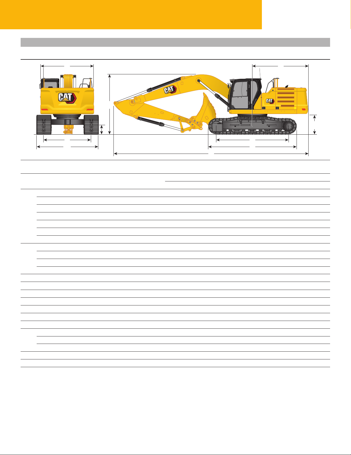
Dimensions
All dimensions are approximate and may vary depending on bucket selection.
1
6
9
10
Boom Option Reach Boom
Stick Options Reach Stick
R3.2CB2 (10'6") R2.65CB2 (8'8")
Machine Height:
1
Cab Height 3060 mm 10'0" 3060 mm 10'0"
FOGS Height 3200 mm 10'6" 3200 mm 10'6"
Handrails Height 3060 mm 10'0" 3060 mm 10'0"
With Boom/Stick/Bucket Installed 3400 mm 11'2" 3450 mm 11'4"
With Boom/Stick Installed 3380 mm 11'1" 3380 mm 11'1"
With Boom Installed 3060 mm 10'0" 3060 mm 10'0"
Machine Length:
2
With Boom/Stick/Bucket Installed 10 420 mm 34'2" 10 420 mm 34'2"
With Boom/Stick Installed 10 420 mm 34'2" 10 420 mm 34'2"
With Boom Installed 9230 mm 30'3" 9230 mm 30'3"
Upperframe Width without Walkways 2940 mm 9'8" 2940 mm 9'8"
3
Tail Swing Radius 3130 mm 10'3" 3130 mm 10'3"
4
Counterweight Clearance 1120 mm 3'8" 1120 mm 3'8"
5
Ground Clearance 490 mm 1'7" 490 mm 1'7"
6
Length to Center of Rollers 3990 mm 13'1" 3990 mm 13'1"
7
Track Length 4860 mm 15'11" 4860 mm 15'11"
8
Track Gauge 2590 mm 8'6" 2590 mm 8'6"
9
Undercarriage Width
10
600 mm (24") Shoes 3190 mm 10'6" 3190 mm 10'6"
700 mm (28") Shoes 3290 mm 10'10" 3290 mm 10'10"
Bucket Type HD HD
Bucket Capacity 1.76 m 2.30 yd 1.76 m 2.30 yd
Bucket Tip Radius 1660 mm 5'5" 1660 mm 5'5"
7
8
6.15 m (20'2")
5
4
Page 5
330 Hydraulic Excavator Specifications
R2.65CB2
Meters
0510152025303540 Feet
Feet
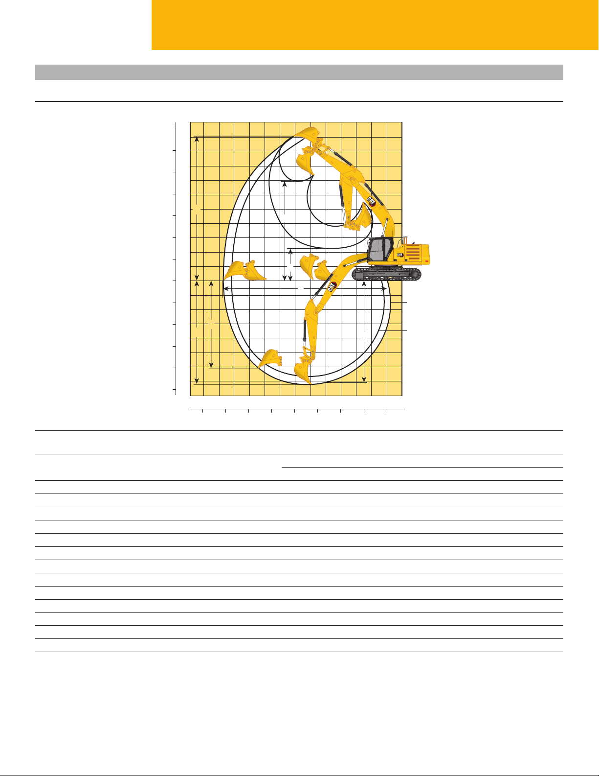
Working Ranges and Forces
All dimensions are approximate and may vary depending on bucket selection.
11
35
10
30
9
8
25
7
20
6
5
15
10
10
15
20
25
3
4
3
2
5
1
0
0
1
5
2
3
7
1
4
5
6
7
1213 11 –1
4
5
2
R3.2CB2
(10'6")
6
(8'8")
012345678910
Meters
Boom Option Reach Boom
6.15 m (20'2")
Stick Options Reach Stick
Maximum Digging Depth 7240 mm 23'9" 6690 mm 21'11"
1
Maximum Reach at Ground Line 10 680 mm 35'0" 10 210 mm 33'6"
2
Maximum Cutting Height 10 030 mm 32'11" 9920 mm 32'7"
3
Maximum Loading Height 6950 mm 22'10" 6800 mm 22'4"
4
Minimum Loading Height 2300 mm 7'7" 2850 mm 9'4"
5
Maximum Depth Cut for 2440 mm (8 ft) Level Bottom 7090 mm 23'3" 6520 mm 21'5"
6
Maximum Vertical Wall Digging Depth 6010 mm 19'9" 5700 mm 18'8"
7
R3.2CB2 (10'6") R2.65CB2 (8'8")
Bucket Digging Force (SAE) 157 kN 35,290 lbf 157 kN 35,290 lbf
Bucket Digging Force (ISO) 179 kN 40,240 lbf 179 kN 40,240 lbf
Stick Digging Force (SAE) 123 kN 27,650 lbf 140 kN 31,470 lbf
Stick Digging Force (ISO) 126 kN 28,330 lbf 145 kN 32,600 lbf
Bucket Type HD HD
Bucket Capacity 1.76 m 2.30 yd 1.76 m 2.30 yd
Bucket Tip Radius 1660 mm 5'5" 1660 mm 5'5"
5
Page 6

330 Hydraulic Excavator Specifications
Reach Boom Lift Capacities – Counterweight: 6700 kg (14,770 lb) – without Bucket, Heavy Lift: On
3.2 m (10'6") 6.15 m (20'2")
R3.2CB2
1500 mm/60 in 3000 mm/120 in 4500 mm/180 in 6000 mm/240 in 7500 mm/300 in 9000 mm/360 in
7500 mm kg *5600 *5600 7280
300 in lb *12,350 *12,350 290
6000 mm kg *7900 6250 *5350 *5350 8240
240 in lb *16,700 13,450 *11,750 *11,750 330
4500 mm kg *9250 8600 *8400 6150 *5300 4750 8830
180 in lb *20,050 18,500 *18,300 13,200 *11,650 10,500 350
3000 mm kg *14 250 12 500 *10 800 8250 9150 5950 *6500 4550 *5450 4450 9140
120 in lb *30,650 27,000 *23,400 17,750 19,650 12,850 *11,950 9,750 360
1500 mm kg *17 000 11 850 *12 300 7900 8950 5800 6800 4450 *5800 4350 9190
60 in lb *36,700 25,500 *26,550 17,000 19,200 12,450 *13,650 9,600 *12,700 9,500 370
0 mm kg *18 300 11 500 12 250 7650 8800 5650 *6350 4400 8990
0 in lb *39,550 24,700 26,350 16,450 18,900 12,150 *14,000 9,700 360
–1500 mm kg *6950 *6950 *10 950 *10 950 *18 250 11 400 12 150 7550 8700 5600 7300 4750 8520
–60 in lb *15,550 *15,550 *24,800 *24,800 *39,600 24,500 26,050 16,250 18,750 12,000 16,050 10,400 340
–3000 mm kg *12 500 *12 500 *17 650 *17 650 *17 150 11 450 12 150 7550 8750 5600 8400 5400 7730
–120 in lb *28,000 *28,000 *40,050 *40,050 *37,100 24,650 26,150 16,250 18,850 12,100 18,600 11,950 310
–4500 mm kg *19 900 *19 900 *14 600 11 700 *10 800 7750 *9500 6950 6510
–180 in lb *42,750 *42,750 *31,300 25,150 *22,850 16,700 *20,850 15,550 260
600 mm (24") Triple Grouser Shoes
2590 mm (8'6") 4860 mm (15'11")
3990 mm (13'1")
Reach Boom Lift Capacities – Counterweight: 6700 kg (14,770 lb) – without Bucket, Heavy Lift: On
mm
in
3.2 m (10'6") 6.15 m (20'2")
R3.2CB2
1500 mm/60 in 3000 mm/120 in 4500 mm/180 in 6000 mm/240 in 7500 mm/300 in 9000 mm/360 in
7500 mm kg *5600 *5600 7280
300 in lb *12,350 *12,350 290
6000 mm kg *7900 6350 *5350 *5350 8240
240 in lb *16,700 13,650 *11,750 *11,750 330
4500 mm kg *9250 8750 *8400 6250 *5300 4850 8830
180 in lb *20,050 18,800 *18,300 13,400 *11,650 10,700 350
3000 mm kg *14 250 12 700 *10 800 8350 *9150 6050 *6500 4600 *5450 4500 9140
120 in lb *30,650 27,400 *23,400 18,000 *19,900 13,050 *11,950 9,950 360
1500 mm kg *17 000 12 000 *12 300 8000 9100 5900 6950 4550 *5800 4400 9190
60 in lb *36,700 25,900 *26,550 17,250 19,550 12,650 *13,650 9,750 *12,700 9,700 370
0 mm kg *18 300 11 700 12 450 7750 8950 5750 *6350 4500 8990
0 in lb *39,550 25,100 26,800 16,750 19,200 12,350 *14,000 9,850 360
–1500 mm kg *6950 *6950 *10 950 *10 950 *18 250 11 600 12 350 7650 8850 5650 *7350 4800 8520
–60 in lb *15,550 *15,550 *24,800 *24,800 *39,600 24,900 26,550 16,500 19,050 12,200 *16,250 10,600 340
–3000 mm kg *12 500 *12 500 *17 650 *17 650 *17 150 11 650 12 350 7700 8900 5700 8550 5500 7730
–120 in lb *28,000 *28,000 *40,050 *40,050 *37,100 25,050 26,600 16,550 19,200 12,350 18,900 12,200 310
–4500 mm kg *19 900 *19 900 *14 600 11 850 *10 800 7850 *9500 7050 6510
–180 in lb *42,750 *42,750 *31,300 25,550 *22,850 16,950 *20,850 15,850 260
* Indicates that the load is limited by hydraulic lifting capacity rather than tipping load. The above loads are in compliance with hydraulic excavator lift capacity standard ISO 10567:2007.
Theydo not exceed 87% of hydraulic lifting capacity or 75% of tipping load. Weight of all lifting accessories must be deducted from the above lifting capacities. Lifting capacities are based
on the machine standing on a firm, uniform supporting surface. The use of a work tool attachment point to handle/lift objects, could affect the machine lift performance.
Lift capacity stays with ±5% for all available track shoes.
Always refer to the appropriate Operation and Maintenance Manual for specific product information.
700 mm (28") HD Triple Grouser Shoes
2590 mm (8'6") 4860 mm (15'11")
ISO 10567
3990 mm (13'1")
mm
in
6
Page 7

330 Hydraulic Excavator Specifications
Reach Boom Lift Capacities – Counterweight: 6700 kg (14,770 lb) – without Bucket, Heavy Lift: On
3.2 m (10'6") 6.15 m (20'2")
R3.2CB2
1500 mm/60 in 3000 mm/120 in 4500 mm/180 in 6000 mm/240 in 7500 mm/300 in 9000 mm/360 in
7500 mm kg *5600 *5600 7280
300 in lb *12,350 *12,350 290
6000 mm kg *7900 6300 *5350 *5350 8240
240 in lb *16,700 13,550 *11,750 *11,750 330
4500 mm kg *9250 8650 *8400 6200 *5300 4800 8830
180 in lb *20,050 18,700 *18,300 13,350 *11,650 10,600 350
3000 mm kg *14 250 12 650 *10 800 8300 *9150 6000 *6500 4600 *5450 4500 9140
120 in lb *30,650 27,250 *23,400 17,900 19,850 12,950 *11,950 9,850 360
1500 mm kg *17 000 11 950 *12 300 7950 9000 5850 6900 4500 *5800 4400 9190
60 in lb *36,700 25,700 *26,550 17,150 19,400 12,550 *13,650 9,700 *12,700 9,600 370
0 mm kg *18 300 11 600 12 400 7700 8850 5700 *6350 4450 8990
0 in lb *39,550 24,950 26,600 16,600 19,050 12,250 *14,000 9,800 360
–1500 mm kg *6950 *6950 *10 950 *10 950 *18 250 11 500 12 250 7600 8800 5650 7350 4750 8520
–60 in lb *15,550 *15,550 *24,800 *24,800 *39,600 24,750 26,350 16,400 18,900 12,150 16,250 10,500 340
–3000 mm kg *12 500 *12 500 *17 650 *17 650 *17 150 11 550 12 300 7650 8850 5650 8500 5450 7730
–120 in lb *28,000 *28,000 *40,050 *40,050 *37,100 24,900 26,400 16,450 19,050 12,250 18,800 12,100 310
–4500 mm kg *19 900 *19 900 *14 600 11 800 *10 800 7800 *9500 7000 6510
–180 in lb *42,750 *42,750 *31,300 25,400 *22,850 16,850 *20,850 15,700 260
600 mm (24") Double Grouser Shoes
2590 mm (8'6") 4860 mm (15'11")
3990 mm (13'1")
Reach Boom Lift Capacities – Counterweight: 6700 kg (14,770 lb) – without Bucket, Heavy Lift: On
mm
in
2.65 m (8'8") 6.15 m (20'2")
R2.65CB2
3000 mm/120 in 4500 mm/180 in 6000 mm/240 in 7500 mm/300 in
7500 mm kg *7300 *7300 6680
300 in lb *19,100 19,050 *16,200 *16,200 260
6000 mm kg *8900 8800 *8350 6200 *6900 5900 7710
240 in lb *19,450 18,900 *15,800 13,250 *15,200 13,150 310
4500 mm kg *12 300 *12 300 *10 050 8500 *8950 6100 *6800 5200 8340
180 in lb *26,400 *26,400 *21,750 18,300 *19,600 13,100 *14,950 11,450 330
3000 mm kg *15 550 12 300 *11 500 8150 9100 5950 *6950 4800 8670
120 in lb *33,350 26,550 *24,850 17,600 19,600 12,800 *15,350 10,600 340
1500 mm kg *16 900 11 750 12 500 7850 8950 5800 7150 4700 8720
60 in lb *38,500 25,250 26,850 16,900 19,200 12,450 15,750 10,300 350
0 mm kg *18 000 11 500 12 250 7650 8800 5700 7350 4800 8510
0 in lb *40,100 24,750 26,400 16,500 18,950 12,200 16,200 10,550 340
–1500 mm kg *10 650 *10 650 *18 000 11 500 12 200 7600 8800 5650 8000 5200 8010
–60 in lb *24,350 *24,350 *39,050 24,700 26,250 16,400 18,900 12,200 17,700 11,450 320
–3000 mm kg *19 950 *19 950 *16 400 11 600 12 300 7650 9450 6100 7170
–120 in lb *45,500 *45,500 *35,550 25,000 26,400 16,550 21,000 13,500 280
–4500 mm kg *13 100 11 900 *9550 8300 5820
–180 in lb *27,950 25,650 *20,950 18,600 230
* Indicates that the load is limited by hydraulic lifting capacity rather than tipping load. The above loads are in compliance with hydraulic excavator lift capacity standard ISO 10567:2007.
Theydo not exceed 87% of hydraulic lifting capacity or 75% of tipping load. Weight of all lifting accessories must be deducted from the above lifting capacities. Lifting capacities are based
on the machine standing on a firm, uniform supporting surface. The use of a work tool attachment point to handle/lift objects, could affect the machine lift performance.
Lift capacity stays with ±5% for all available track shoes.
Always refer to the appropriate Operation and Maintenance Manual for specific product information.
600 mm (24") Triple Grouser Shoes
2590 mm (8'6") 4860 mm (15'11")
ISO 10567
3990 mm (13'1")
mm
in
7
Page 8

330 Hydraulic Excavator Specifications
Reach Boom Lift Capacities – Counterweight: 6700 kg (14,770 lb) – without Bucket, Heavy Lift: On
2.65 m (8'8") 6.15 m (20'2")
R2.65CB2
3000 mm/120 in 4500 mm/180 in 6000 mm/240 in 7500 mm/300 in
7500 mm kg *7300 *7300 6680
300 in lb *19,100 *19,100 *16,200 *16,200 260
6000 mm kg *8900 8900 *8350 6300 *6900 6000 7710
240 in lb *19,450 19,150 *15,800 13,450 *15,200 13,400 310
4500 mm kg *12 300 *12 300 *10 050 8650 *8950 6200 *6800 5250 8340
180 in lb *26,400 *26,400 *21,750 18,600 *19,600 13,350 *14,950 11,650 330
3000 mm kg *15 550 12 500 *11 500 8300 9250 6050 *6950 4900 8670
120 in lb *33,350 26,950 *24,850 17,850 19,900 13,000 *15,350 10,750 340
1500 mm kg *16 900 11 900 12 700 8000 9100 5900 7300 4750 8720
60 in lb *38,500 25,700 27,300 17,200 19,550 12,650 16,050 10,500 350
0 mm kg *18 000 11 700 12 500 7800 8950 5750 7500 4900 8510
0 in lb *40,100 25,200 26,850 16,800 19,300 12,450 16,500 10,750 340
–1500 mm kg *10 650 *10 650 *18 000 11 700 12 400 7750 8950 5750 8150 5300 8010
–60 in lb *24,350 *24,350 *39,050 25,150 26,700 16,650 19,250 12,400 18,000 11,650 320
–3000 mm kg *19 950 *19 950 *16 400 11 800 *12 450 7800 9650 6200 7170
–120 in lb *45,500 *45,500 *35,550 25,400 *26,850 16,800 21,400 13,700 280
–4500 mm kg *13 100 12 100 *9550 8400 5820
–180 in lb *27,950 26,050 *20,950 18,900 230
700 mm (28") HD Triple Grouser Shoes
2590 mm (8'6") 4860 mm (15'11")
3990 mm (13'1")
Reach Boom Lift Capacities – Counterweight: 6700 kg (14,770 lb) – without Bucket, Heavy Lift: On
mm
in
2.65 m (8'8") 6.15 m (20'2")
R2.65CB2
3000 mm/120 in 4500 mm/180 in 6000 mm/240 in 7500 mm/300 in
7500 mm kg *7300 *7300 6680
300 in lb *19,100 *19,100 *16,200 *16,200 260
6000 mm kg *8900 8850 *8350 6250 *6900 6000 7710
240 in lb *19,450 19,050 *15,800 13,400 *15,200 13,300 310
4500 mm kg *12 300 *12 300 *10 050 8600 *8950 6150 *6800 5250 8340
180 in lb *26,400 *26,400 *21,750 18,500 *19,600 13,250 *14,950 11,550 330
3000 mm kg *15 550 12 400 *11 500 8250 9200 6000 *6950 4850 8670
120 in lb *33,350 26,800 *24,850 17,750 19,750 12,900 *15,350 10,700 340
1500 mm kg *16 900 11 850 12 600 7950 9000 5850 7250 4750 8720
60 in lb *38,500 25,500 27,100 17,100 19,400 12,600 15,950 10,400 350
0 mm kg *18 000 11 600 12 400 7750 8900 5750 7450 4850 8510
0 in lb *40,100 25,000 26,650 16,700 19,150 12,350 16,400 10,650 340
–1500 mm kg *10 650 *10 650 *18 000 11 600 12 350 7700 8850 5700 8100 5250 8010
–60 in lb *24,350 *24,350 *39,050 24,950 26,500 16,550 19,100 12,300 17,850 11,550 320
–3000 mm kg *19 950 *19 950 *16 400 11 700 12 400 7750 9550 6150 7170
–120 in lb *45,500 *45,500 *35,550 25,200 26,650 16,700 21,200 13,600 280
–4500 mm kg *13 100 12 000 *9550 8350 5820
–180 in lb *27,950 25,850 *20,950 18,800 230
* Indicates that the load is limited by hydraulic lifting capacity rather than tipping load. The above loads are in compliance with hydraulic excavator lift capacity standard ISO 10567:2007.
Theydo not exceed 87% of hydraulic lifting capacity or 75% of tipping load. Weight of all lifting accessories must be deducted from the above lifting capacities. Lifting capacities are based
on the machine standing on a firm, uniform supporting surface. The use of a work tool attachment point to handle/lift objects, could affect the machine lift performance.
Lift capacity stays with ±5% for all available track shoes.
Always refer to the appropriate Operation and Maintenance Manual for specific product information.
600 mm (24") Double Grouser Shoes
2590 mm (8'6") 4860 mm (15'11")
ISO 10567
3990 mm (13'1")
mm
in
8
Page 9

330 Hydraulic Excavator Specifications
Bucket Specifications and Compatibility
Width Capacity Weight Fill
Linkage
Pin-On (No Quick Coupler)
General Duty CB 600 24 0.52 0.68 659 1,454 100
CB 750 30 0.71 0.93 726 1,601 100
CB 1000 40 1.03 1.35 835 1,841 100
CB 1350 54 1.54 2.02 1005 2,216 100
CB 1500 60 1.76 2.30 1069 2,357 100
CB 1600 63 1.86 2.43 1099 2,423 100
Heavy Duty CB 1200 48 1.33 1.74 1096 2,417 100
CB 1350 54 1.54 2.02 1196 2,637 100
Heavy Duty CB 1450 57 1.60 2.09 1274 2,809 100
CB 1600 63 1.80 2.36 1348 2,973 100
Heavy Duty CB 1500 60 1.76 2.30 1391 3,067 100
With Pin Grabber Quick Coupler
General Duty CB 600 24 0.52 0.68 659 1,454 100
CB 750 30 0.71 0.93 726 1,601 100
CB 1000 40 1.03 1.35 835 1,841 100
CB 1350 54 1.54 2.02 1005 2,216 100
CB 1500 60 1.76 2.30 1069 2,357 100
CB 1600 63 1.86 2.43 1099 2,423 100
Heavy Duty CB 1200 48 1.33 1.74 1096 2,417 100
CB 1350 54 1.54 2.02 1196 2,637 100
Heavy Duty CB 1450 57 1.60 2.09 1274 2,809 100
CB 1600 63 1.80 2.36 1348 2,973 100
Heavy Duty CB 1500 60 1.76 2.30 1391 3,067 100
mm in m yd kg lb % R3.2 (10'6") R2.65 (8'8")
Maximum load with pin-on (payload + bucket)
Maximum load with coupler (payload + bucket)
kg 4605 5045
kg 4079 4519
6.7 mt (14,770 lb)
Counterweight
Reach Boom
X X
X X
lb 10,152 11,122
lb 8,992 9,962
The above loads are in compliance with hydraulic excavator standard EN474-5:2006+A3:2013, they do not exceed 87%
ofhydraulic lifting capacity or 75% of tipping capacity with front linkage fully extended at ground line with bucket curled.
Capacity based on ISO 7451:2007.
Bucket weight with General Duty tips.
Caterpillar recommends using appropriate work tools to maximize the value customers receive from our products. Use of work tools, including buckets, which are outside of Caterpillar’s
recommendations or specifications for weight, dimensions, flows, pressures, etc. may result in less-than-optimal performance, including but not limited to reductions in production, stability,
reliability, and component durability. Improper use of a work tool resulting in sweeping, prying, twisting and/or catching of heavy loads will reduce the life of the boom and stick.
Maximum Material Density:
2100 kg/m (3,500 lb/yd)
1800 kg/m (3,000 lb/yd)
1500 kg/m (2,500 lb/yd)
X Not Recommended
9
Page 10

330 Hydraulic Excavator Specifications
Attachments Offering Guide
Not all Attachments are available in all regions. Consult your Cat dealer for congurations available in your region.
Match
ü
PIN-ON ATTACHMENTS
Undercarriage L
Counterweight 6.7 mt (14,770 lb)
Boom Type Reach Reach
Stick Length 2.65 m (8'8") 3.2 m (10'6")
Hydraulic Hammers H120 S
Demolition and Sorting Grapples G324
Mobile Scrap and Demolition Shears S3025
CAT PIN GRABBER COUPLER ATTACHMENTS
Undercarriage L
Counterweight 6.7 mt (14,770 lb)
Boom Type Reach Reach
Stick Length 2.65 m (8'8") 3.2 m (10'6")
Hydraulic Hammers H120 S
Demolition and Sorting Grapples G324
Mobile Scrap and Demolition Shears S3025
BOOM-MOUNT ATTACHMENTS
Undercarriage L
Counterweight 6.7 mt (14,770 lb)
Boom Type Reach Reach HD
Mobile Scrap and Demolition Shears S2070
Allowed usage on machine less than 50%
†
H130 GC
H130 GC S
H130 S
H140 GC
H140 GC S
H140 S
H160 GC
H160 GC S
G332
S3035
H130 GC
H130 GC S
H130 S
H140 GC
H140 GC S
H140 S
H160 GC
H160 GC S
G332
S3035
S3050
ü ü
ü ü
ü ü
ü ü
ü ü
ü ü
ü ü
ü ü
ü ü
ü ü
ü ü
ü ü
ü ü
ü ü
ü ü
ü ü
ü ü
ü ü
ü ü
ü ü
ü ü
ü ü
ü ü†
ü ü†
ü ü
ü ü
ü ü
ü ü
10
Page 11

330 Standard and Optional Equipment
Standard and Optional Equipment
Standard and optional equipment may vary. Consult your Cat dealer for details.
CAB
ROPS, standard sound suppression
High-resolution 254 mm (10") LCD
touchscreen monitor
High-resolution 254 mm (10") LCD
touchscreen monitor + additional
monitor (only for use with Cat GRADE
with Advanced 2D or Cat GRADE
with3D)
Tilt-up left-side console
Heated seat with air-adjustable suspension
Height-adjustable console, innite with
no tool
Automatic bi-level air conditioner
Jog dial and shortcut keys for
monitorcontrol
Keyless push-to-start engine control
51 mm (2") seat belt
®
Bluetooth
USBports
12V DC outlets
Document storage
Rear head storage net and
lunchboxstorage net
Cup and bottle holders
Openable two-piece front window
Upper radial wiper with washer
Openable polycarbonate skylight hatch
LED dome light
Floor welcome light
Roller front sunscreen
Roller rear sunscreen
Rear window emergency exit
Washable oor mat
Beacon ready
integrated radio with
Standard Optional
ü
ü
ü
ü
ü
ü
ü
ü
ü
ü
ü
ü
ü
ü
ü
ü
ü
ü
ü
ü
ü
ü
ü
ü
ü
CAT TECHNOLOGY
Cat Product Link™
Work tool recognition
Work tool tracking*
Laser catcher
Cat GRADE with 2D and offset memory
Cat GRADE with Advanced 2D
Cat GRADE with 3D connectivity:
– Virtual Reference Station**
– Internet Base Service Station**
– Trimble Connected Community**
Cat Assist:
– Grade Assist
– Boom Assist
– Bucket Assist
– Swing Assist
– Lift Assist
Cat PAYLOAD:
– Static weigh
– Semiautomatic calibration
– Payload/cycle information
– USB reporting capability
2D E-Fence:
– E-ceiling
– E-oor
– E-swing
– E-wall
– E-cab avoidance
Auto hammer stop
Remote Services capability
Auto Dig Boost
*Paired with PL161 attachment locator.
**Subscription required.
Standard Optional
ü
ü
ü
ü
ü
ü
ü
ü
ü
ü
ü
ü
ü
(continued on next page)
11
Page 12

330 Standard and Optional Equipment
Standard and Optional Equipment (continued)
Standard and optional equipment may vary. Consult your Cat dealer for details.
ENGINE
Three selectable modes: Power,
Smart,Eco
Automatic engine speed control
Automatic engine idle-shutdown
4500 m (14,760 ft) altitude capability
with engine power derate above 3000 m
(9,840 ft)
52° C (125° F) high-ambient cooling
capability with derate
–18° C (0° F) cold start capability
2 × 115 amp dual alternator
Sealed double element air lter with
integrated precleaner
Two-stage fuel ltration with water
separator and indicator
Electric fuel priming pump
Electric cooling fans with auto-reverse
function
Biodiesel capability up to B20
HYDRAULIC SYSTEM
Electronic main control valve
Electric boom regeneration circuit
Stick regeneration circuit
Automatic hydraulic oil warm up
Automatic two-speed travel
Boom and stick drift reduction valve
Boom lowering check valve
Stick lowering check valve
Heavy lift mode
High performance hydraulic return lter
Final drive with bio hydraulic oil
capabletravel motor
Fine swing control
Hammer return lter circuit
Advanced Tool Control (two pump,
one/two way high-pressure ow)
Medium-pressure circuit
Common Quick Coupler Circuit for
CatPin Grabber and CW Dedicated
Electronic Pattern Changer
(requiresactivation)
Standard Optional
ü
ü
ü
ü
ü
ü
ü
ü
ü
ü
ü
ü
ü
ü
ü
ü
ü
ü
ü
ü
ü
ü
ü
ü
ü
ü
ü
ü
ü
BOOM, STICKS AND LINKAGES
6.15 m (20'2") Reach boom
3.2 m (10'6") Reach stick, CB2 Linkage
2.65 m (8'8") Reach stick, CB2 Linkage
Bucket Linkage, CB2 family with
liftingeye, Cat GRADE
UNDERCARRIAGE AND STRUCTURES
Full-length track guiding guards
Segmented track guiding guards
Swivel guard
Bottom guard
HD bottom guard
HD travel motor guard
Grease lubricated track
Swing drive and motor, and swing
bearing for higher swing torque
Base frame with HD rollers
Tie-down points on base frame
6700 kg (14,770 lb) counterweight
600 mm (24") triple grouser track shoes
600 mm (24") double grouser track shoes
700 mm (28") triple grouser HD
trackshoes
Standard Optional
ü
ü
ü
ü
ü
ü
ü
ü
ü
ü
ü
ü
ü
ü
ü
ü
ü
ü
(continued on next page)
12
Page 13

330 Standard and Optional Equipment
Standard and Optional Equipment (continued)
Standard and optional equipment may vary. Consult your Cat dealer for details.
ELECTRICAL SYSTEM
Maintenance-free 1,000 CCA
batteries(×2)
Programmable time-delay LED
workinglights
Centralized electrical disconnect switch
LED chassis light, LH and RH boom
lights, cab lights
Premium surround lighting package
SERVICE AND MAINTENANCE
Grouped location of engine oil
andfuellters
Ground-level second dipstick
forengineoil
Side entry to service platform
SM
Scheduled Oil Sampling (S·O·S
QuickEvac™ maintenance ready
Radiator screen
) ports
Standard Optional
ü
ü
ü
ü
ü
ü
ü
ü
ü
ü
ü
SAFETY AND SECURITY
Rearview camera
Right-hand-sideview camera
360° visibility
Secure start with PIN code
Caterpillar One Key security system
Lockable external tool/storage box
Lockable door, fuel, and hydraulic
tanklocks
Lockable fuel drain compartment
Service platform with anti-skid plate
andrecessed bolts
RH handrail and hand hold
(ISO2867:2011compliant)
Cab mirror for RH track edge
Signaling/warning horn
Ground-level secondary engine shutoff
switch in cab
Hydraulic lock out lever that neutralizes
all controls
Travel alarm
Standard Optional
ü
ü
ü
ü
ü
ü
ü
ü
ü
ü
ü
ü
ü
ü
ü
13
Page 14

330 Attachments
Dealer Installed Kits and Attachments
Attachments may vary. Consult your Cat dealer for details.
CAB
• RH electrical pedal (two-way) for
toolcontrol
• Radial lower wiper for two piece (70/30)
windshield, with washer
• Rain protector plus cab light cover
SAFETY AND SECURITY
• 75 mm (3") retractable seat belt
• Bluetooth key fob
GUARDS
• Side rubber bumper guard
• Falling object guard system (not compatible
with cab light cover, rain protector)
• Mesh guard full front (not compatible with
cab light cover, rain protector)
• Full protecting vandalism guard
(notcompatible with cab light cover,
rainprotector)
ELECTRICAL
• Jump start wiring
SERVICE AND MAINTENANCE
• Grease gun holder
For more complete information on Cat products, dealer services, andindustry solutions, visit us on the web
atwww.cat.com
© 2020 Caterpillar
All rights reserved
Materials and specications are subject to change without notice. Featured machines in photos may include
additional equipment. See your Cat dealer for available options.
CAT, CATERPILLAR, LET’S DO THE WORK, their respective logos, “Caterpillar Corporate Yellow,” the
“PowerEdge” and Cat “Modern Hex” trade dress as well as corporate and product identity used herein,
are trademarks ofCaterpillar and may not be used without permission.
AEXJ0085-03 (08-2020)
Replaces AEXJ0085-02
Build Number: 07C
(ANZ)
 Loading...