

Page 1
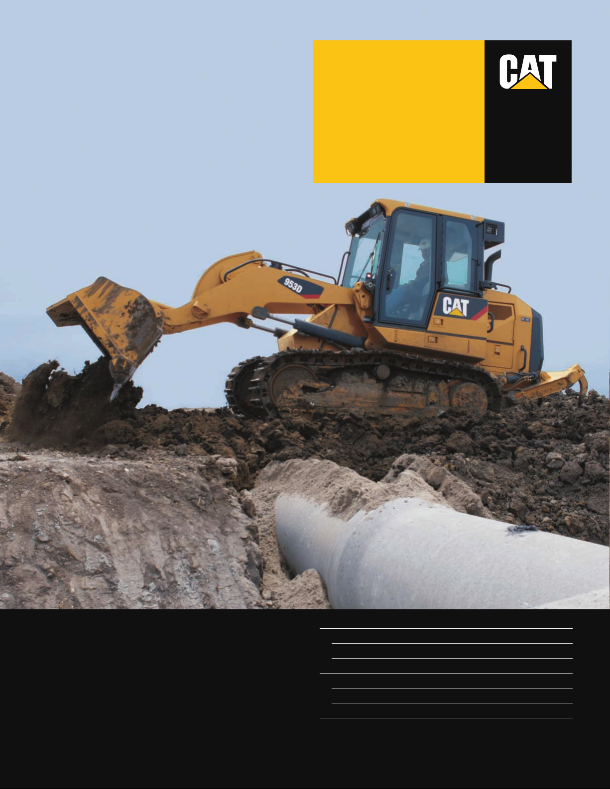
Engine
Engine Model Cat®C6.6 ACERT™
Flywheel Power 110 kW 148 hp
Buckets
Capacity – General Purpose 1.85 m
3
2.42 yd
3
Capacity – Multi-Purpose 1.6 m
3
2.09 yd
3
Weights
Operating Weight 15 517 kg 34,209 lb
953D
Track Loader
®
®
Page 2
2
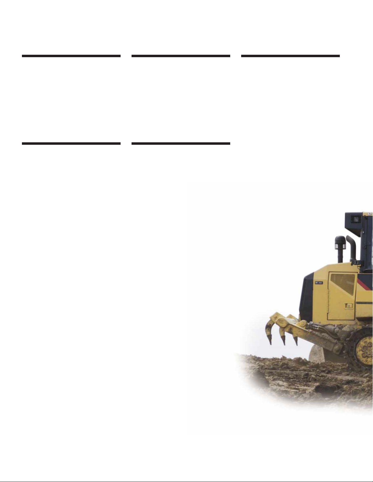
953D Track Loader
Increased horsepower, excellent
maneuverability, redesigned operator cab
for comfort, the revolutionary SystemOne™
undercarriage and the new implement system
increase your productivity, drastically reduce
your operating costs and make the new 953D
unsurpassed in versatility.
Versatility
A large choice of buckets, Ground
Engaging Tools (GET), and attachments,
allow configuration of the 953D for
maximum performance in any job.
Cat work tools retain the proven shelltine construction design for unmatched
durability. pg. 14
SystemOne™ Undercarriage
The revolutionary Cat SystemOne
Undercarriage provides maximum
undercarriage life and reliability no matter
the application, environment or underfoot
conditions. Built to last longer and require
less maintenance it ensures a dramatic
drop in owning and operating costs. pg. 12
Monitoring System
The 953D incorporates a new smooth,
rounded, molded gauge cluster with
integral defroster vents. Together with
Cat®Messenger, it displays all necessary
information within the operator’s normal
line of sight. pg. 8
✔
Operator Station
Experience a high level of efficiency,
comfort and productivity with the new
D-series cab. The cab features a new
gauge cluster, a fully air-suspension
seat, the new seat mounted controls,
an automatic air climate control and
provides excellent visibility. pg. 6
✔
Engine
The Cat®C6.6 ACERT engine utilizes
the Caterpillar®Common Rail fuel
delivery system. Designed for
performance, durability, serviceability,
and fuel economy, it meets EPA Tier 3,
EU Stage IIIA and Japan Ministry of
Land, Infrastructure & Transport Step 3
emission standards. pg. 4
✔
Page 3
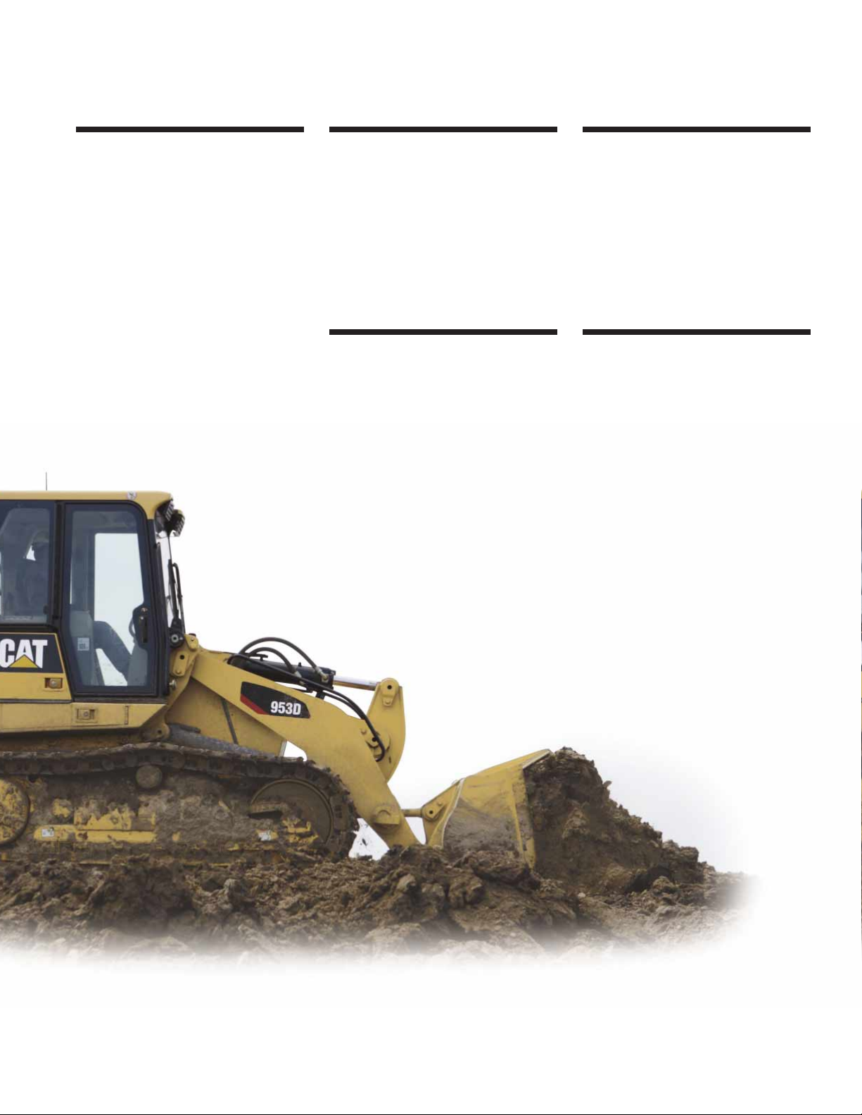
✔ New Feature
3
Special Application Arrangements
Special arrangements – Waste Handling,
Wide Gauge and more, are available or
can be designed on request, to allow the
953D to work in special applications.
pg. 18
Serviceability and Customer Support
The new 953D is equipped with a tiltable
cab that allows complete service of the
hydraulic system. Most daily maintenance
checks are performed from the machine’s
right side. pg. 16
✔
Structure
The D-series Main Frame and Loader
Tower provide durability, resistance
to twisting, and a solid base for all
components. The Z-bar linkage offers
high breakout force and fast dump
speed for enhanced productivity. pg. 11
✔
Implement System
The 953D features a load sensing
implement pump which reduces engine
power consumption. The new electrohydraulic implement controls lower the
operator’s effort. And the new position
sensing cylinders allow setting detents
at any positions from the cab. pg. 10
✔
Hydrostatic Drive
The closed loop hydrostatic drive
with electronic control provides precise
modulation for quick, smooth operation
and superior maneuverability.
Shorter cycle times, high efficiency,
and excellent maneuverability results
in increased productivity. pg. 9
✔
Page 4
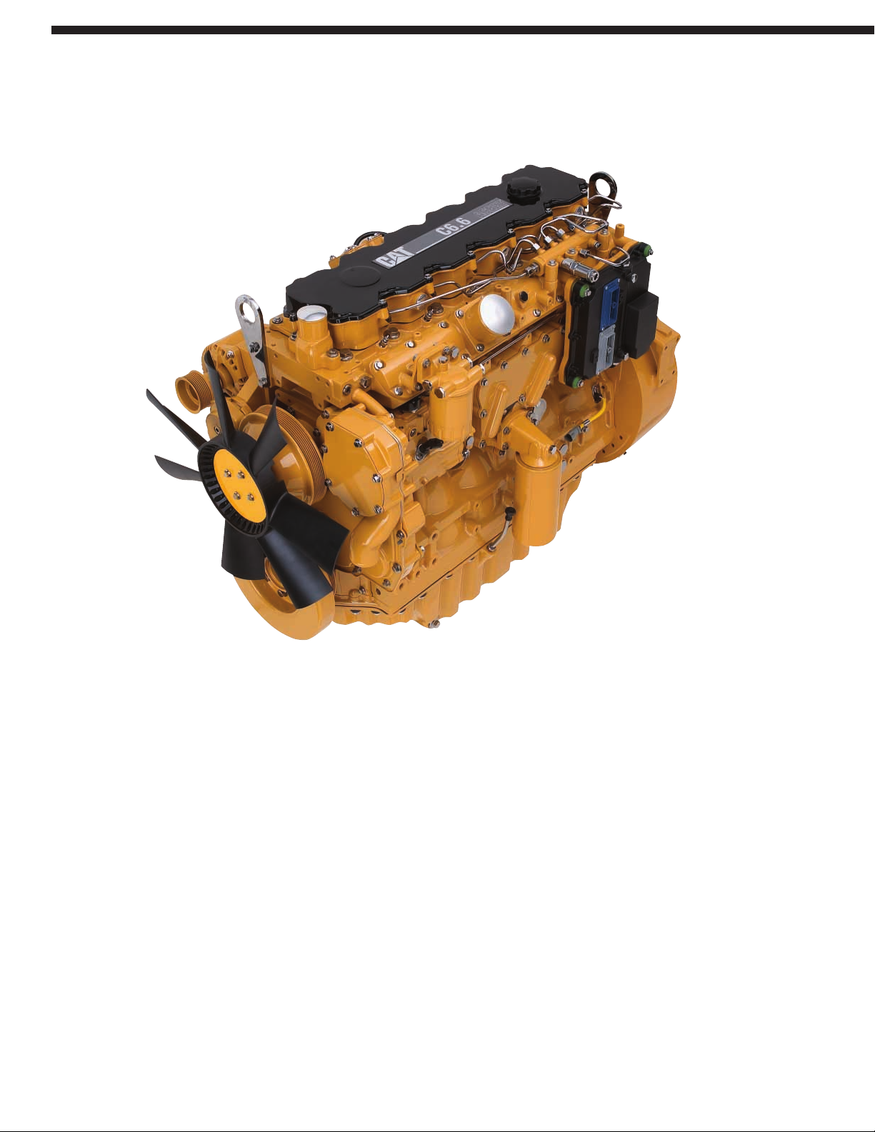
Cat C6.6 ACERT™. The Cat®C6.6 is
a 6.6 liter (403 in3) displacement, sixcylinder, in-line configured engine that
utilizes the Caterpillar®Common Rail
fuel system for fuel delivery. It uses
ACERT™ Technology, a series of
Caterpillar engineered innovations that
provide advanced electronic control,
precision fuel delivery and refined air
management, resulting in outstanding
performance and lower emissions.
The C6.6 with ACERT Technology offers
a compact design with big, heavy-duty
engine features for outstanding durability,
reliability and performance. The C6.6
incorporates a new cross flow cylinder
head design, 4 valve head and an
ADEM™ A4 electronic controller.
The C6.6 also features proven cylinder
block, pistons and crankshaft and
incorporates the common rail fuel
system. ACERT™ Technology enables
the C6.6 engine to meet the U.S. EPA
Tier 3, European Union Stage IIIA and
Japan Ministry of Land, Infrastructure
& Transport Step 3 emissions standards,
which dramatically reduce nitrogen
oxide (NOx) and other emissions.
ACERT™ Technology used on the C6.6
consists of three basic building block
systems: electronic control, fuel delivery,
and air management. These have been
refined to control the combustion
process to a higher degree than ever
before possible.
Electronic control ADEM™ A4.
The Advanced Diesel Engine
Management – Electronic Control
Module continuously monitors important
engine conditions and functions. It uses
sensors throughout the engine to regulate
fuel delivery and all other engine systems
that require input to manage load and
performance. ADEM™ A4 is the brain
behind engine responsiveness, selfdiagnosis, controlling emissions, and
fuel economy.
4
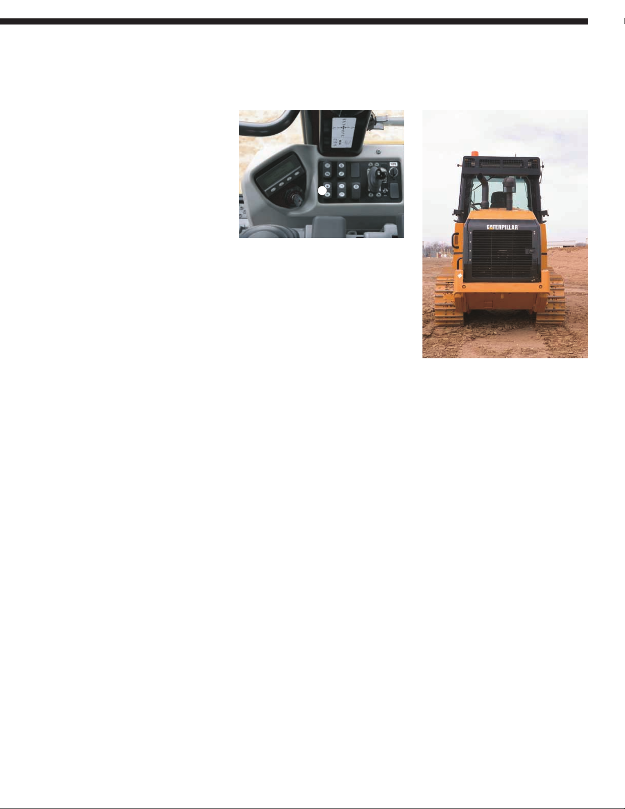
Provides power, reliability and acts as a working counterweight in the rear of the machine,
for optimum machine balance.
Engine
Page 5
Fuel System. Through multiple injection
fuel delivery, fuel is introduced in the
combustion chamber in a number
of precisely controlled microburst.
Injecting fuel in this way allows for
precise shaping of the combustion
cycle. The ADEM™ A4 module directs
the injectors to deliver precise quantities
of fuel at exactly the right times during
combustion cycle.
This process provides precise control
over a range of combustion variables,
which can be regulated to produce
higher performance with fewer
emissions. Fuel is delivered at high
pressure to each combustion chamber
through a Caterpillar designed injector
linked to a high pressure Common Rail.
Air Management. Air management
is a key concept in optimizing engine
performance and controlling emissions.
Engines must breathe clean cool air in
order to perform. To aid this, the C6.6
uses a turbocharger fitted with a smart
waste gate to give precise and reliable
control of the boost pressure. A new
cross-flow design in the cylinder head
facilitates air movement, while tighter
tolerances between the piston and
cylinder liner are reducing blow by gases.
Fuel pump. The C6.6 uses an oillubricated high-pressure fuel pump to
feed the common rail. By using an oillubricated fuel pump, the C6.6 has
been designed to be more tolerant
of alternative fuels.
Fuel Priming Pump. An electrical fuelpriming pump, standard, is located
between the fuel tank and the combined
water separator/primary fuel filter.
Starting System. The Electronic Speed
Selector Switch (A), a “rocker” switch
located on the right console, sets the
engine rpm. The ADEM A4 engine
controller will always start the engine
in low idle. The engine rpm can be seen
on the digital display of the instrument
cluster in the gage cluster or in the
performance menu in Messenger.
Air-to-Air After cooler (ATAAC).
The air-to-air after cooler is a single pass,
aluminum, heat exchanger or cooling
system for the pressurized air coming
from the turbocharger, before it enters
the engine intake manifold. Cooling the
pressurized air from the turbocharger
makes the engine intake air even denser.
The increased air volume in the cylinders
results in more power, improved
combustion, and reduced exhaust
emissions.
Servicability. Unit injectors and high
pressure fuel lines can be serviced
individually, without the need
to service the whole fuel system.
Engine Installation. The engine is
installed using rubber mounts to reduce
the transfer of engine vibration to the
frame and cab, lowering operator
vibration, sound levels, and fatigue.
Rear Engine Location. Rear engine
location allows excellent forward
visibility, while serving as a working
counterweight. It also helps reduce
radiator plugging while providing easy
service access to the engine and other
major components.
Cooling module architecture. The cooling
system is a single cooling unit, which
includes Radiator, ATAAC, Oil cooler
and Fan installation. The cooling module
is located at the rear of the loader, away
from dust and debris stirred up by the
bucket while the machine is working.
Hydraulic on-demand fan. The fan is a
hydraulic demand type one with optional
reversible function, operating in sucker
mode. It gives the best efficiency and
avoids also sucking the dust and debris
coming from the outside into the
cooling package.
The complete cooling package has been
designed for a very easy maintenance
with a complete accessibility to the cores
for cleaning (fan door swing out opening,
latches), and a very high safety level.
A
5
Page 6
6
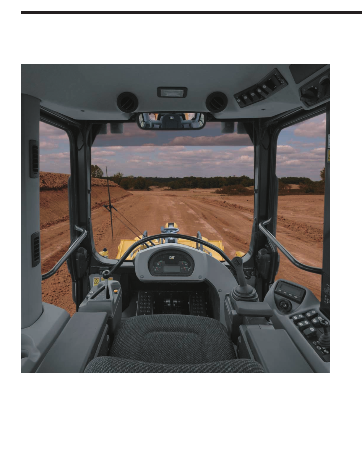
Designed for operator comfort, convenience, and ease of operation throughout the workday.
Operator Station
Page 7
Heating and Air Conditioning.
Air conditioning is standard on 953D.
Both the air conditioning and the heater
deliver filtered, pressurized, temperaturecontrolled air to the operator and windows
through 10 louvered vents.
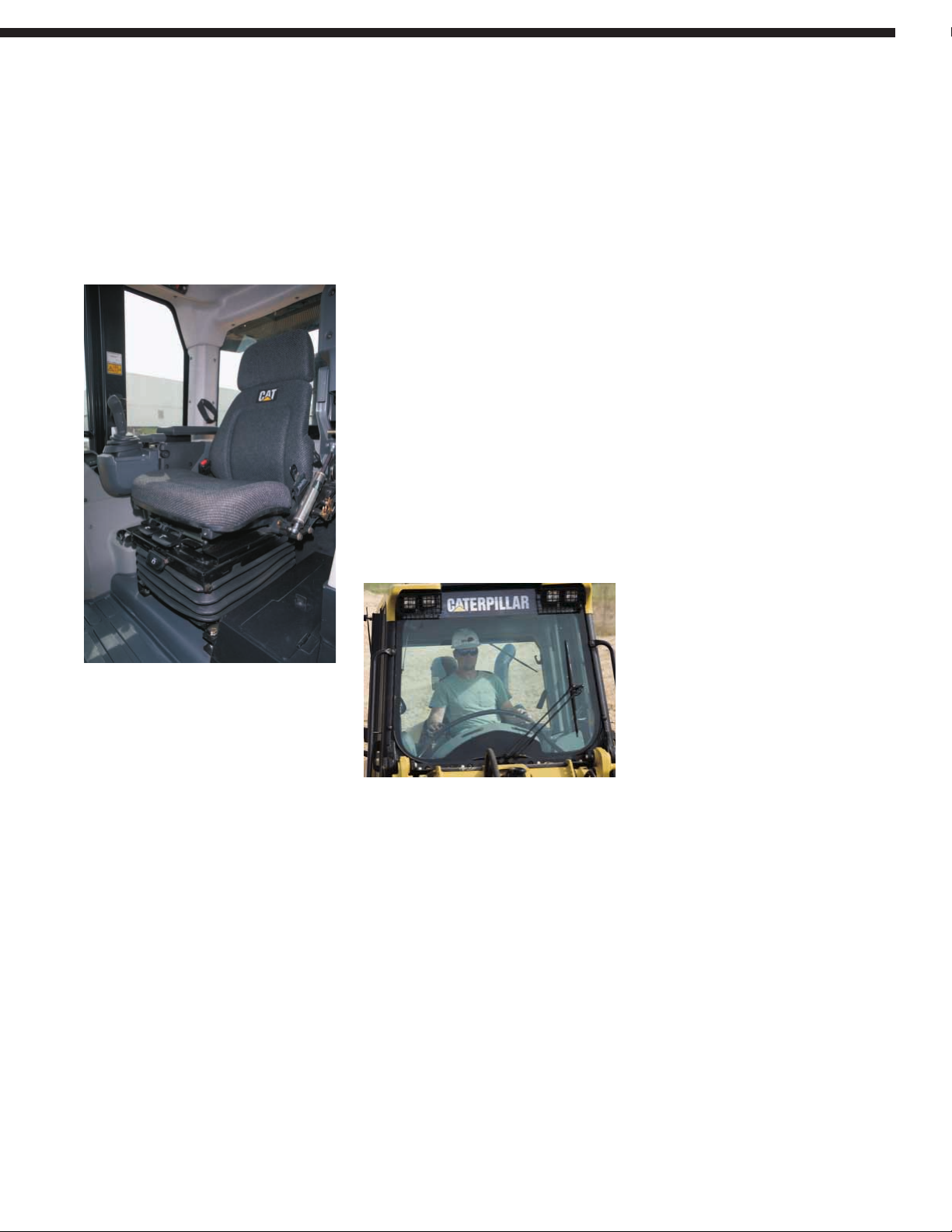
Caterpillar Air-suspension Seat.
The Caterpillar air-suspension seat, with
side-to-side isolator, is ergonomically
designed and fully adjustable for
maximum operator comfort and control.
Retractable seat belt is 75 mm (3 in)
wide for positive, comfortable restraint.
Seat mounted controls. Seat mounted
controls provide less vibration for the
operator and a combined seat and
controls adjustment.
Armrests. The right hand side console
features an adjustable armrest, wrist rest
and joystick mount. The left armrest
height is adjustable.
Total adjustability lets the operator
customize the armrests to the most
comfortable position.
Messenger. Messenger is a new electronic
monitoring system with real-time, visual
feedback on engine and machine operating
conditions. It provides information
on diagnostic data, maintenance,
and allows operating settings such
as implement reactions.
Electro-hydraulic implements controls.
The new electro hydraulic implement
controls on the 953D provide the operator
with responsive, smooth and precise
control of bucket and lift arms. Choice of
joystick or two-lever control is available
for bucket lift and dump.
Kickout settings. Automatic kickouts
are part of the electro-hydraulic controls;
adjust from inside the cab with a simple
rocker switch. Kickout stops are
hydraulically cushioned for greater
operator comfort and less material
spillage.
Viewing Area. Large windows use tinted
glass to reduce glare and provide an
excellent view to the bucket, tracks, and
around the engine enclosure to the rear.
Side windows slide top down to allow
the operator to let fresh air into the cab
and communicate.
Rearview Mirror. The rearview mirror
is located above the front windshield,
maximizing the operator’s visibility.
Dome Light. A dome light is located
in the cab headliner.
Radio Installation Arrangement.
A standard feature in the cab is a Radio
Installation, which includes a 24-volt to
12-volt converter and speakers.
A Caterpillar heavy-duty (AM/FM)
radio/CD player and satellite radios
are available from dealers.
Storage spaces. Storage spaces include
a removable lunch box, a beverage holder
and storage and a coat holder.
Working lights. Up to eight working
lights are available on the 953D.
Door release lever. The door’s release
lever is accessible from the ground and
the seat to unlock the door conveniently.
Machine Security System.
Eliminate machine theft and unauthorized
usage with the Cat Machine Security
System (MSS). It is integrated into the
machine’s electronic system and can
protect your equipment by requiring a
uniquely coded key to start the machine.
7
Page 8
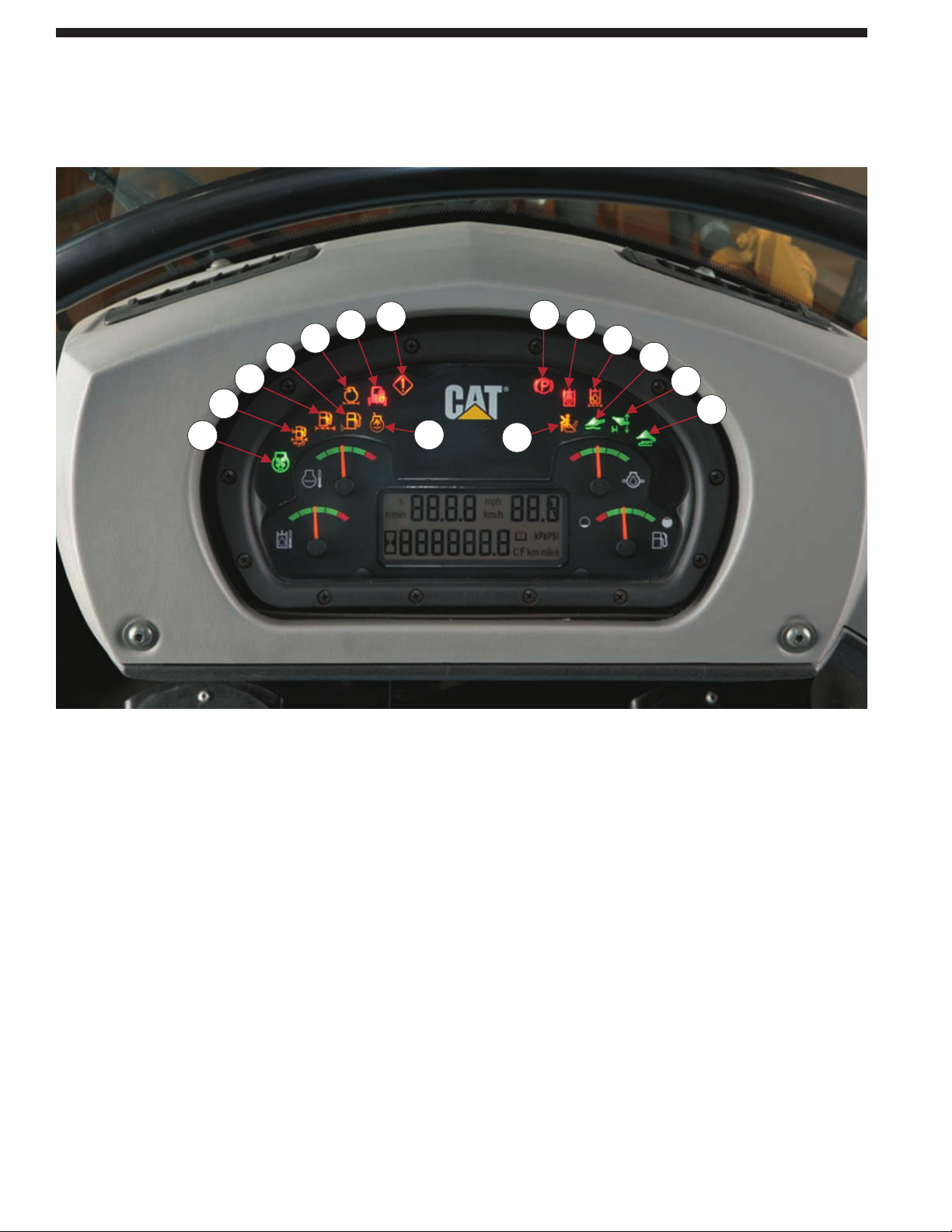
The 953D gauge cluster display.
The gauge cluster provides all necessary
information within the operator’s normal
line of sight.
The 953D gauge cluster display includes:
• Four direct reading gauges
• Fifteen alert indicators
• A numeric message display
• Gauge Cluster
Alert indicators. The fifteen alert
indicators used on the 953D are:
1. Reversible fan
2. Water separator
3. Fuel filters plugging
4. Fuel level
5. Engine air filter plugging
6. Machine security system
7. Ether starting aid
8. Warning lamp
9. Parking brake
10. Operator presence
11. Hydraulic lockout
12. Hydraulic oil filter
13. Bucket float
14. Lift kickout/lower kickout
15. Bucket leveler
Gage cluster-self test. The gauge cluster
self-test verifies that the main display
module is operating properly every time
the key start switch is turned from the
“off” to the “on” position.
NOTE – If the machine is not equipped
with Messenger, the numeric display
will show fault codes.
8
Monitoring System
The gauge cluster provides all necessary functions and information within the operator’s
normal line of sight.
4
3
2
1
8
6
5
7
10
9
11
12
13
14
15
Page 9
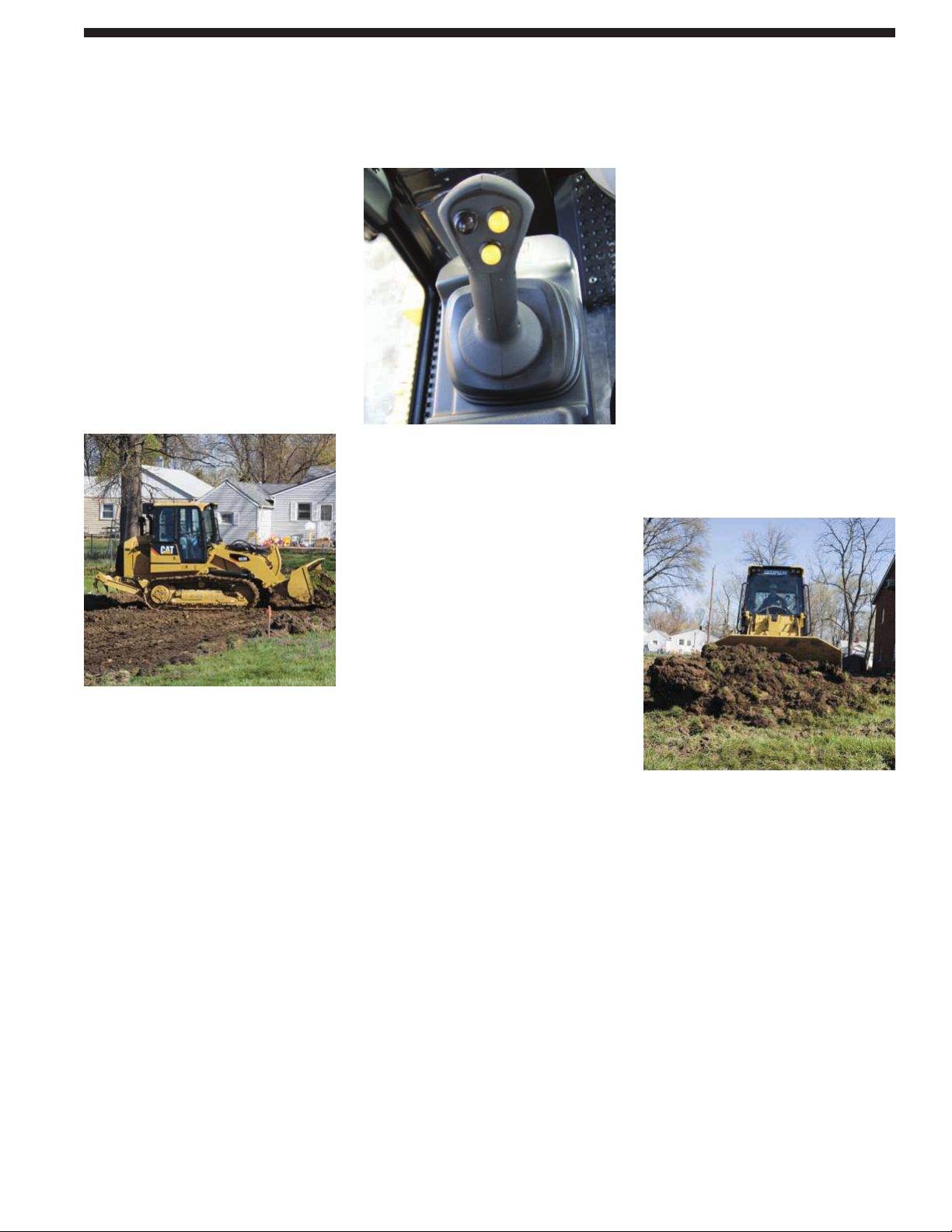
The electronically controlled hydrostatic
drive system automatically matches
machine travel speed to the combined
travel and implement loads on the
machine, enabling maximum travel
speed, up to the speed selected by
the operator.
Electronic Hydrostatic Control (EHC).
Hydrostatic system has integrated
electro-hydraulic controls, sized for
optimum performance and efficiency.
Position in the machine provides
ease of access for serviceability.
Variable Displacement Pumps and Drive
Motors. Variable displacement pumps and
drive motors are electronically controlled
by the EHC, offering high efficiency and
precise travel. Each track is independently
driven by a separate hydraulic circuit
consisting of one pump, connected
by Cat XT-6™ hydraulic hose
and couplings to a piston motor.
Fuel Management System. This system
allows the operator to select a lower
RPM setting for reverse. Three selections
are available in Messenger to match the
engine speed in reverse to the application.
Full speed is achievable in all settings.
Travel Speeds. Travel speeds are
infinitely variable between zero and top
speed. Two speed modes “work” and
“travel”, provide two different speed
ranges to best match machine speed and
torque to the job conditions for maximum
productivity. Maximum travel speed is
10 kph (6.2 mph) when the switch is set
in the travel position.
Hydrostatic Drive System Controls.
The control systems allow quick speed
and directional changes. Two power train
contol options are available:
1. The V-lever system includes a single
speed direction control lever and
steering pedals that can be adjusted
from 35° to 50° depending on operator
preference and allow precise control
of each track independently and
on-demand counter rotation. An
emergency brake pedal is located
between the two steering pedals.
2. The joystick system features an
S-lever pattern steering including
a single joystick handle for speed,
direction and steering functions,
foot rests and an emergency brake
pedal. Counter rotation is possible
from moving or immobile machine.
This power train control system
is comparable to the drive system
known from the Cat Multi Terrain
and Skid Steer Loaders. A black
button is located on the top to activate
the horn.
Speed Switches. Both systems include
speed mode switches.
For the V-lever system a “work mode”
and “travel mode” switch allows to best
match the machine speed to various job
conditions. Switching between travel
and work mode takes effect immediately.
The joystick includes two yellow buttons
for maximum transmission speed setting.
It features three machine travel speed
limits, to best match application and
controllability requirements. Limit increase
and decrease take effect immediately.
Steering. Steering is accomplished by
changing relative pump flows and/or
motor displacements, which causes one
track to rotate slower than the other track.
Maneuverability. The hydrostatic drive
train also offers independent power
and control of each track, with fast
acceleration, infinitely variable speeds,
and automatic, on-the-go, direction
changes for each track. The operator
can command smooth “power turns”
or even counter-rotation of the tracks
by simply pushing one of the steering
pedals, if the machine is equipped with
the V-lever, or moving the joystick in
the right/left axis while the machine
is stationary. The Caterpillar hydrostatic
drive system manages itself, freeing
the operator to concentrate on using
the Cat track loader’s superb agility,
speed, and maneuverability to do
more productive work.
9
Hydrostatic Drive
The electronically controlled hydrostatic drive helps provide quick response for shorter
cycle times and increased productivity.
Page 10
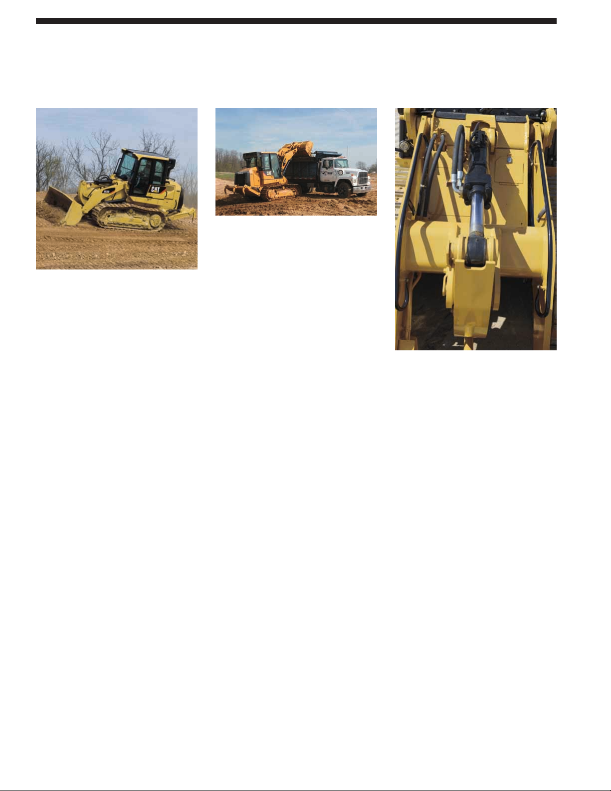
Electro-hydraulic Implement Controls.
Electro hydraulic implement controls
on the 953D provide the operator with
responsive, smooth and precise control
of bucket and lift arms. They also allow
the operator to set personal parameters
through the optional Messenger such as
implement reactions.
Automatic kick-outs. The standard
programmable automatic kick-outs
provide flexibility and productivity
for precise load and dump target heights.
Tilt and lift kickouts are set by positioning
the bucket or work tool and setting
a rocker switch in the cab.
Load sensing hydraulics. The 953D
features a load sensing hydraulic system
that automatically adjusts to operating
conditions to provide only the hydraulic
flow required by the implement for
improved fuel efficiency.
Position sensing cylinder.
Position sensing cylinders allows to:
• Set detents at any positions according
to the applications without operator
leaving the cab
• Advanced automatic features as drop
catch (accelerate and stop smoothly)
and snubbing (smooths start and
stop cylinder motion)
• Set tilt and lift kickouts
• Sensing of the cylinder end of stroke
• Prevent unintended motion.
10
Implement System
Work smart and move more.
Page 11
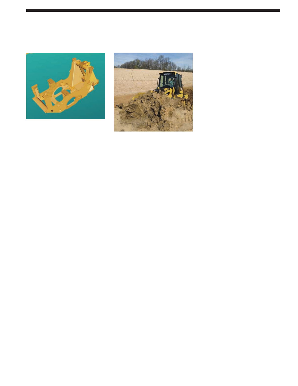
Mainframe and Loader Tower. The 953D
Main Frame and Loader Tower is a single,
slab rails with reinforced crossings, with
castings and forgings incorporated at
points of high stress, to distribute those
stresses over wider areas for long
structural life.
Design. The part of the frame below the
engine and operator’s station consists of
two slab-section side-frame rails, which
are joined at the rear by a box-section
cross member. The Slab-section 953D
frame resists twisting and impact forces
to provide a solid foundation for all the
components it supports. Mounting points
for the final drives, pivot shafts, and
platform are built into each mainframe
side rail.
Frame side plates. The frame side plates
are made of mild steel, which provides
strength and resists shock and bending
stresses. “Deep penetrating”, “Backed up”
welds are used for maximum strength.
Loader tower. The loader tower is integral
with the basic main frame. The one slab
plate continues forward to become one
side of the loader tower in order to provide
smooth transition to loads from linkages
to the mainframe rails. The loader tower
provides a solid mount for lift arms,
lift cylinders, and Z-bar tilt cylinder.
A box-section cross member is welded
below the two inboard loader tower
plates to add strength. The equalizer
bar, which connects the track roller
frames to the main frame, is mounted
below the loader tower. The result is an
integrated main frame and loader tower
assembly which will accommodate
maximum loads capability. The engine
is at the rear, where its weight serves as
a “working counterweight” to balance the
machine for full bucket loads without
adding inefficient “dead” weight.
Z-Bar linkage. Breakout force is
exceptionally high due to mechanical
advantage of Z-bar linkage design, and
hydraulic pressure applied to the head
end of the tilt cylinder. Using a single
tilt cylinder and linkage provides the
operator a better view of the work
area, bucket, and cutting edge.
Sealed Loader Linkage. The 953D linkage
has fewer grease points compared to other
linkage designs because every pin joint
is sealed to keep grease in and dirt out.
Fewer grease points and sealed pins
means less downtime for maintenance
allowing more working hours between
servicing.
Lift Arms. The two arms are welded into
a single unit, using a weld-fabricated
cross-tube.
The tilt link (Dog Bone) is a single
forging. The 953D linkage design
combines the advantages of strength
and durability with minimum structural
weight, so that productivity is not
penalized by excess weight in
the linkage.
11
Structure
Durable slab section frame and loader tower with increased space for larger components.
Page 12
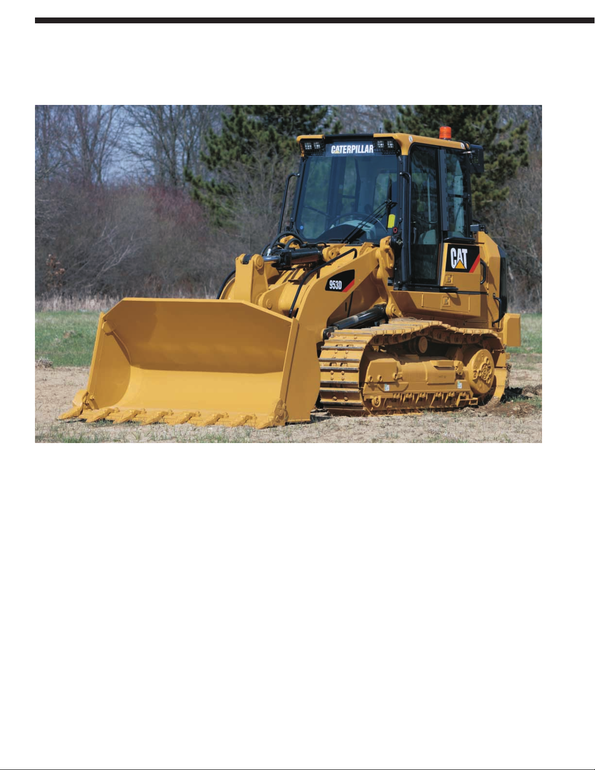
Revolutionary Undercarriage.
SystemOne™ is the latest innovation in
a century of undercarriage leadership.
Nearly every major undercarriage
improvement over the last 100 years has
come from Caterpillar. It was designed
to reduce customers’ operating costs
and maintenance intervals.
The revolutionary Cat SystemOne™
Undercarriage provides maximum
undercarriage life and reliability no
matter the application, environment
or underfoot conditions. Built to last
longer and require less maintenance
it ensures a dramatic drop in
operating costs.
Track Roller Frames. The track roller
frames are a welded, box section design,
which provides strength and resistance
to bending without adding extra weight.
The track roller frames are pinned at the
rear to the loader main frame with pivot
shafts, which allow the front of the track
roller frames to swing or oscillate about
the pivot shafts at the rear.
Guiding System. Better, more rigid
guiding. The guiding system contacts
link rails instead of pin ends and helps
keep the track within the roller system.
Rollers. The 953D has six track rollers,
which spread machine weight over a
large area and a single upper carrier
roller on each side mounts to the
machine mainframe.
The rollers and carrier rollers have
been redesigned to run with the system.
This will lead directly to better guiding.
All rollers in this new system are all
single flange rollers with increased
flange diameter. This will also increase
your guiding capability.
12
The SystemOne undercarriage was designed exclusively for Caterpillar machines to reduce
customers’ operating costs, downtime and maintenance intervals.
SystemOne™ Undercarriage
Page 13
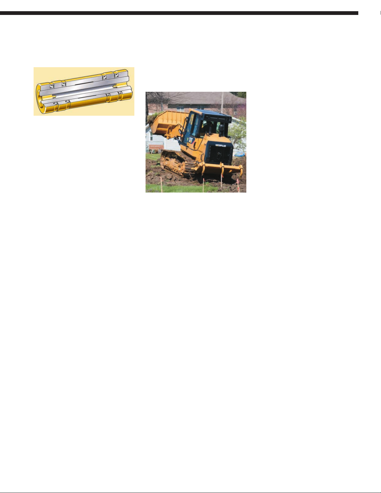
Cartridge Joints. Factory-sealed cartridge
joints are welded to control end play.
They offer improved seal integrity
through an innovative new sealing
system and do not depend on the link
interface to remain sealed. As with all
new Cat undercarriage products,
they are filled with special oils.
Track Shoes. The shoes for SystemOne™
are unique to this system. Several track
shoe types tailor your machine for
work in all underfoot conditions.
The SystemOne links have a straight
rather than offset bolt hole pattern.
Double grouser standard or narrow track
shoes are available. The standard shoe
can be fitted with center hole to reduce
material packing.
Long-life Sprockets. The sprockets, thanks
to the rotating bushing design track, will
be able to be reused over the life of a
couple of undercarriages. This helps
to cut down on replacement cost.
Idlers. New redesigned idlers, specifically
optimized for the track type loaders to
maximize performance and comfort.
Oscillating Undercarriage.
The undercarriage on the 953D features
an “oscillating track roller frame design”
which decreases ground shock to the
machine, increases machine stability, and
provides a smoother, more comfortable
ride for the operator. Oscillating track
roller frames keep more of the track on
the ground when operating on uneven
terrain, which increases machine stability,
felt by the operator, allowing faster
machine operation, increased machine
productivity and reduced operator fatigue.
Track Adjuster. The track adjuster and
mechanical recoil system uses a large
recoil spring and grease filled adjustment
cylinder, which allows the idler to move
forward and back to maintain proper
track tension as it absorbs undercarriage
shock loads.
Equalizer Bar. The equalizer bar is pinned
in its center to the machine mainframe
and at the ends to each track roller frame.
This allows the forward ends of the track
roller frames to oscillate, or move
vertically, to keep more track on the
ground in uneven underfoot conditions.
The equalizer bar also provides a more
stable work platform for the operator,
who will be comfortable working at
faster speeds for increased productivity.
13
Page 14
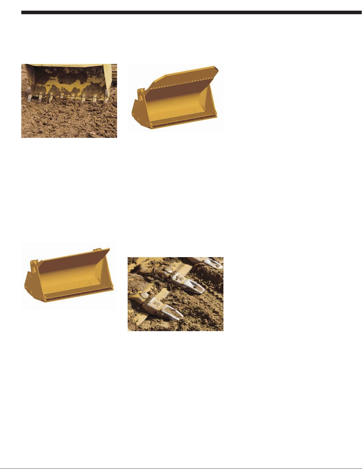
General Purpose Bucket. The General
Purpose (GP) bucket is designed for
excellent loadability and long life in a
broad range of applications such as hard
bank excavating, stripping and stockpile
loading. High-strength, low-alloy
steel helps the bucket resist dents
and abrasions.
The bucket is made of high-strength,
low-alloy steel plate for resistance
to dents and abrasions. The shell-tine
design in the bucket back and floor
offers increased structural strength.
Multi-Purpose Bucket. The Multi-Purpose
(MP) bucket combines the performances
of a standard bucket, dozer blade and
clamp. The bucket provides maximum
versatility combined with strength to
handle a broad range of applications,
such as loading, stripping topsoil,
clearing, bulldozing, picking up
debris and fine grading.
General Purpose Landfill Bucket.
With the integrated trash-rack, the
General Purpose Landfill (GP Landfill)
bucket becomes ideal for digging,
loading and carrying as well as dozing
and spreading material at landfills,
or loading refuse at a transfer station.
Multi-Purpose Landfill Bucket.
The Multi-Purpose Landfill (MP Landfill)
bucket combines the versatility of
a Multi-Purpose bucket with the
performance of a landfill design.
Constructed with a trash-rack for
increased capacity, extra strength
and better load retention. Ideal for
applications in the harsh refuse market,
whether digging or spreading material
at the landfill or grasping and loading
refuse at a transfer station.
Bucket Protection Options. Caterpillar
offers several types of adapters, tips, and
cutting edges, which increase bucket life
and maximize performance.
K Series™ Tooth System. The K-Series
tooth system provides longer tip and
adapter life, faster cycle time with greater
bucket fills and reduced machine strain.
Therefore, it contributes to the reduction
of operating costs.
Easy and convenient during the
installation, this new system provides
a very good response to the need
of reliability and durability
of such components.
Longer Tooth Life. Tips are installed with
a slight twist and secured with a one-piece
retainer, providing less tip movement
and nose wear.
Stable System Geometry. Opposing,
sloped rails on the adapter provide
full length stabilization with minimal
movement. The tip bears directly on the
end of the adapter nose to absorb thrust
loads, leading to better tip retention and
a longer adapter life.
Easy Installation and Removal.
Opposing sloped side rails and flanks
keep the tip on the nose as the retainer is
being installed and removed. The onepiece vertical retainer requires low force
and no special tools, allowing faster and
easier removal and installation, amounting
to less machine down time for tip changes.
Sharper Digging Profile. Lower height at
the front and the back of the nose provides
a sharper profile. This provides more
production, less machine strain and
lower cost of machine operation.
14
The large variety of tasks an operator can perform with the standard machine and
Work Tools has lead to the Caterpillar Track Loader’s reputation for versatility.
Versatility
Page 15
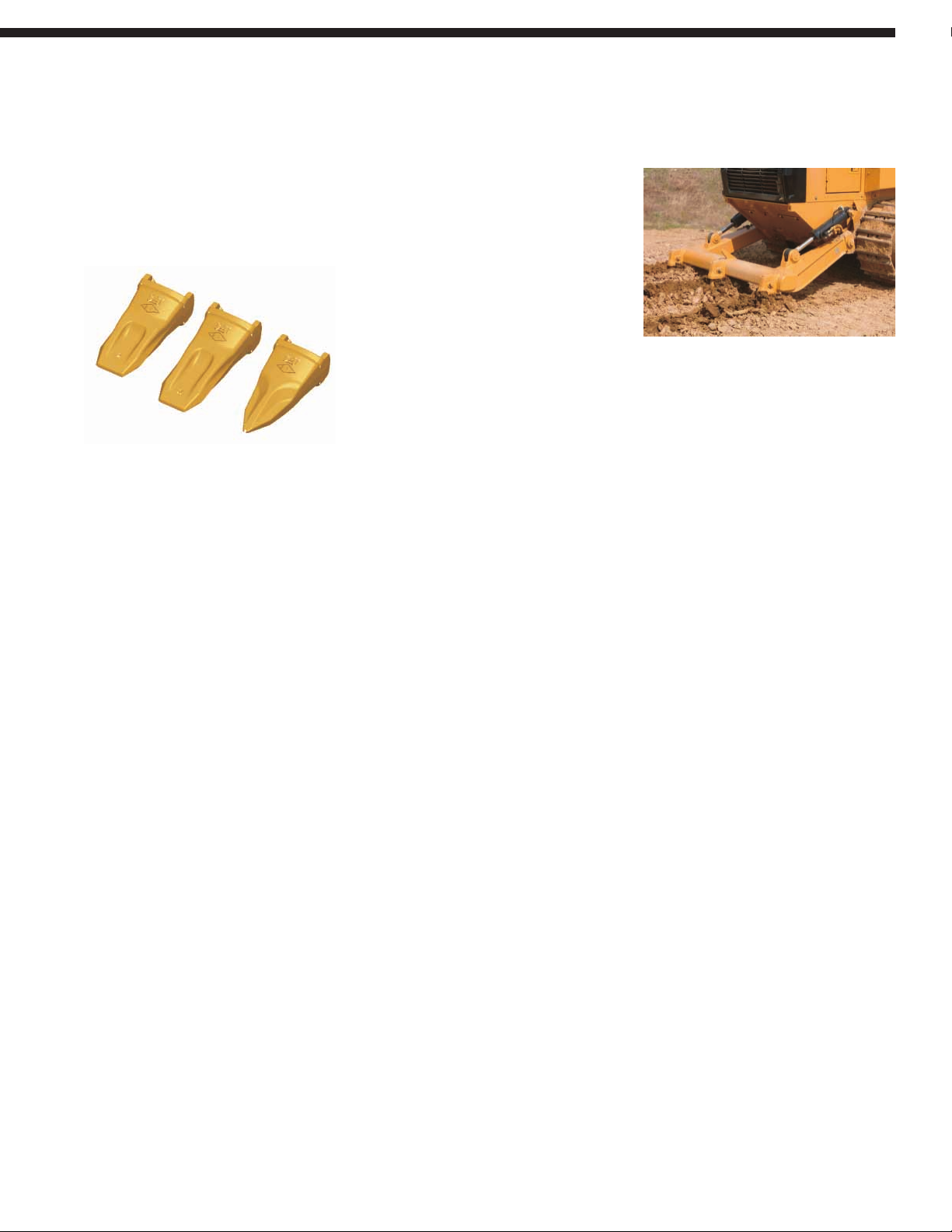
Reversible Tips. Each tip ear has a retainer
groove with a locking recess. Tips can
be run in one direction, then “flipped,”
or reversed, to get the maximum use
of wear material from the tip.
Tip Options. Caterpillar GET offers a
variety of tips to better accommodate
your needs in any working environment,
whether that is high impact or generalpurpose applications.
These and other GET options are
available from your Caterpillar Dealer.
Penetration Tips. Pentration tips are
extremely strong and are for use in high
impact and pry-out work such as rock.
General Duty Tips. General duty tips are
for use in most general applications where
breakage is not a concern.
Extra-duty Tips. Extra-duty tips are for
use in general loading and excavation
work. They have thirty-six percent more
wear material than on general duty tips.
Provides increased strength, extended
service life, and low cost-per-hour.
Ripper-Scarifier. A radial ripper-scarifier
is available for the 953D as an attachment.
It is mounted with two pins pressed
into each side of the main frame.
Two cylinders raise and lower the ripper.
The ripper beam has three pockets for
holding ripper shanks. The six pins in
the linkage do not require lubrication.
The 953D ripper-scarifier is intended
for ripping frozen ground, asphalt and
easily ripped rock. It is not designed
for hard rock.
Additional Work Tools. Beyond the GP
and MP buckets and the Ripper-scarifier
your Cat dealer offers: Side-Dump
Buckets, Landfill Buckets, Straight
Trim Blades, Pallet Forks, Extendible
Material Handling Arms, and
Quick Couplers.
15
Page 16
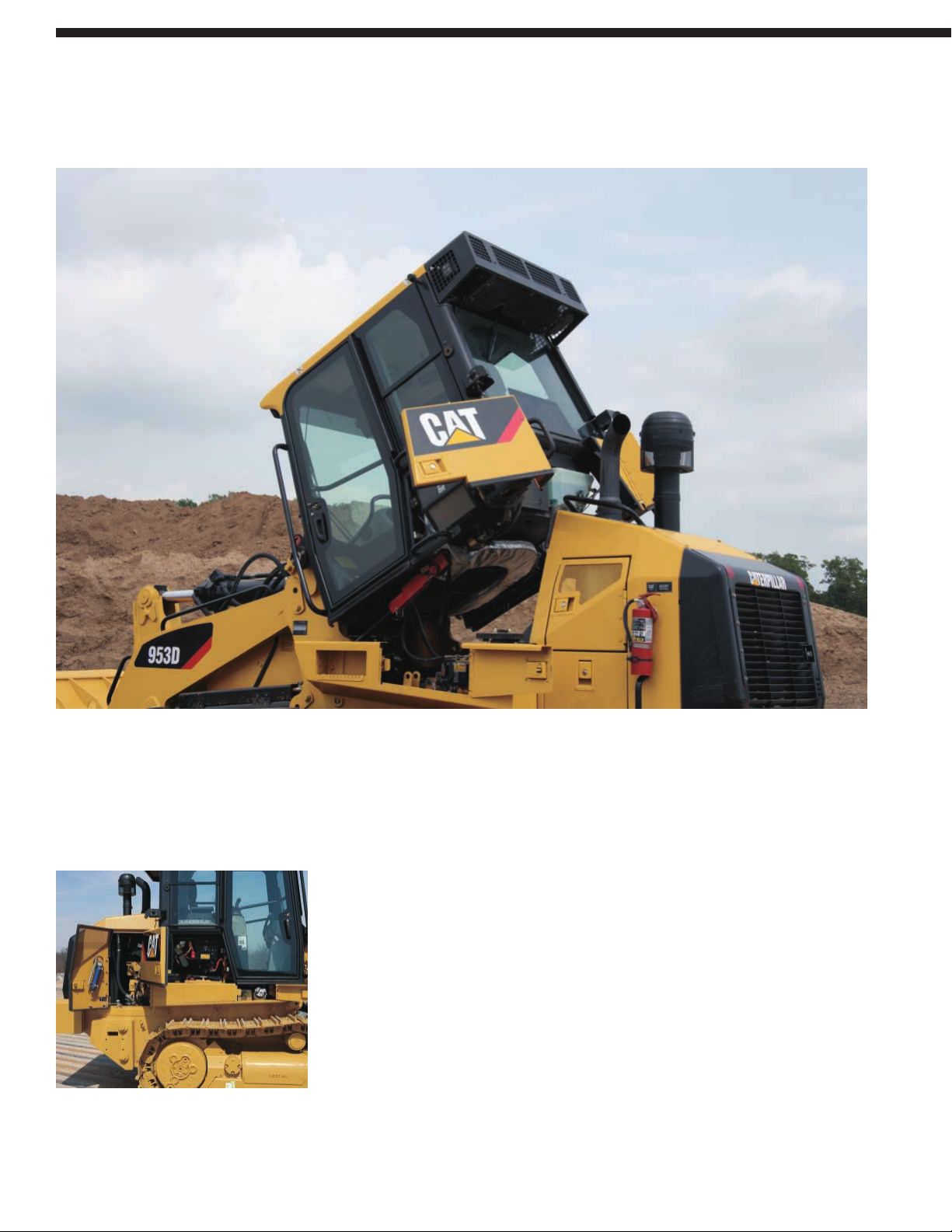
Tiltable Cab. The 953D is equipped
with a tiltable cab. This feature makes
the maintenance and the repairs easier.
By tilting the cab, you can access to
the drive train and perform complete
service of the hydraulic system.
Right side compartments.
• The fuel tank and the optional quick
fill port are located on the right side
compartment, below the cab access.
• The two maintenance-free batteries,
the machine ECM and the window
washer reservoir are located on the
right side compartment, accessible
from the ground.
• The engine compartment has large
hinged openings with latches. On the
door, you can clip a grease gun.
You can access to the following
maintenance and service points:
Primary and secondary engine air filter
Engine air pre-cleaner
Water in fuel separator
Fuel filter
Engine crankcase breather filter
Engine oil filter
The sediment pump (option)
The electric fuel-priming pump
The dipstick for the oil level in the
engine crankcase and the fill tube
The electrical disconnect switch
16
Grouped service points and excellent accessibility make the 953D easy to maintain.
Serviceability and Customer Support
Page 17
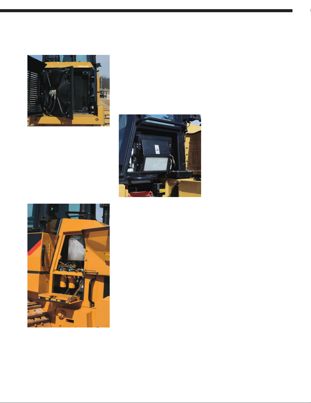
Cooling System. The fan and the grill
swing open, providing excellent access
for clean-out and maintenance. The heavy
duty latched grill minimizes debris
build-up.
Ground Level Shutdown. The Engine
Control ECM monitors the status of a
switch that is mounted behind a cover
at the rear of the machine, allowing the
machine to be shut down from ground
level in emergency situations.
Left side compartments. Left engine
compartment includes two spin-on
hydraulic oil filters that provide
filtration for the hydrostatic system.
The lower part of the compartment door
can be used as a step to access the shunt
tank fill, the air pre-cleaner (if equipped)
and allows easy cleaning of the rear
window.
Cab Air Filter. The cab air filter, the
grouped pressure taps, the cab tilt locking
bar, the optional tilt cylinder and the tool
box are conveniently located below the
left-side cab window.
Hydraulic Tank. The hydraulic tank is
located in the front of the machine. It is
accessible without raising the lift arms.
A site gauge allows oil level check from
the ground.
Fuse Panel. The fuse panel is located
to the inside of the cab, on the rear right
side console. It includes the ET port.
Easy Diagnosis. The gauge cluster and
self-diagnosing Electronic Hydraulic
Control (EHC) work together to warn
against faults to reduce downtime.
S•O•S Fluid Taps. Simplifies drawing
fluid samples for Scheduled Oil Sampling
and reduces sample contamination.
Quick-Connect Fittings. The quickconnect hydraulic grouped pressure taps
allow quick diagnosis of the hydrostatic
drive and the implement hydraulic
systems.
Product Link. This attachment allows
the customer or dealer to remotely obtain
machine diagnostics. Product Link
provides updates on service meter hours,
machine condition, machine location,
and integrated mapping/route planning.
Complete Customer Support. Cat field
service technicians have the experience
and tools necessary to service your loader
on site. Technical experts at the dealership
and Caterpillar can provide additional
assistance to field service technicians
as needed. When on-site repair isn’t
enough, Cat dealerships are fully
equipped to service your loader quickly.
Shovel Holder. As an optional attachment,
a shovel holder, located on the rear right
side of the machine, is available for
undercarriage cleaning.
SAFETY.CAT.COM™.
17
Page 18
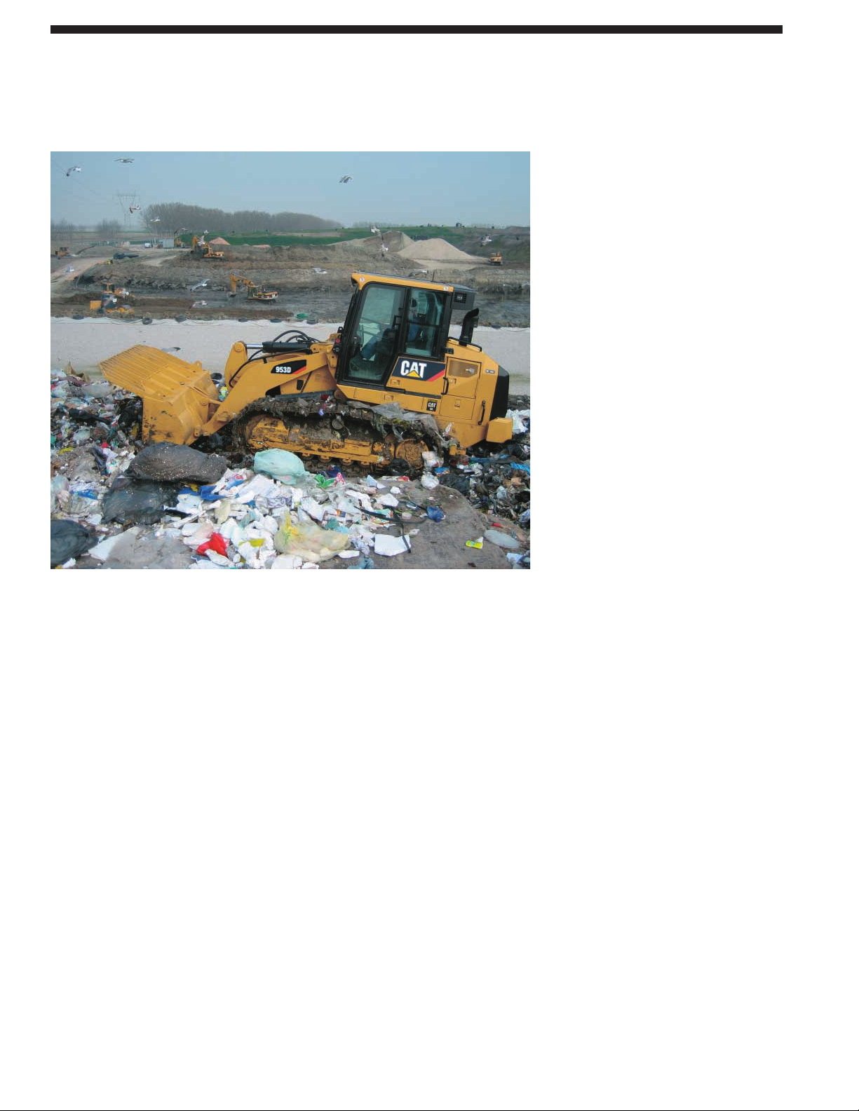
With the addition of certain special
modifications, the capabilities of the
953D can be further expanded to handle
some very harsh working conditions.
Waste Handling Arrangements.
Waste Handling arrangements provide
added protection and are designed to
make the 953D perform well in landfills,
or any waste handling applications where
the machine spreads, compacts, sorts,
shreds and crushes materials.
Shiphold Arrangement. The 953D with
its low ground pressure and excellent
stability works well on top of loose
materials, cleaning the cargo from the
sides of the holds and moving it into
position for the unloading system.
Lifting eyes are included so that the 953D
can be lifted from the dock to the hold.
Wide Gauge. For underfoot conditions
that require even lower ground pressure
than the standard 953D undercarriage
the gauge of the machine can be widened
by 300 mm (11.8 inches) and the track
shoe width increased to 800 mm
(31.5 inches). The ground pressure
is decreased to 43.3 kPa (6.3 psi).
Custom Products Arrangements.
Other arrangements beyond those
shown here are available. For other
custom-designed arrangements for
specific applications, contact your
Caterpillar Dealer.
18
Special Application Arrangements
Special arrangements improve the 953D’s performance in special applications.
Page 19

19
953D Track Loader specifications
Drive System
Type Hydrostatic drive with
infinite machine speeds
to 10.0 km/h (6.2 mph)
Drive Pump Two variable-displacement,
slipper-type axial
piston pumps
Track Motor Two variable-displacement,
bend axis motors
Relief Valve Setting 47 500 kPa 6,890 psi
Service Refill Capacities
Fuel Tank 316 L 83.5 gal
Cooling System 31 L 8 gal
Crankcase (with Filter) 16.5 L 4.4 gal
Final Drives (each) 10.8 L 2.8 gal
Hydraulic Tank 70 L 18.5 gal
Pivot Shaft 0.7 L 0.18 gal
Electrical System
Type 24V DC
Battery Capacity 950 CCA
Battery Voltage 12
Battery Quantity 2
Alternator 95 Amps, Heavy-Duty
Brushless
Weights
Operating Weight 15 517 kg 34,209 lb
Shipping Weight 14 217 kg 31,343 lb
• Operating Weight: Includes coolant, lubricants, 100% fuel
tank, ROPS/FOPS cab, General Purpose Bucket with long
bolt-on teeth and segments and 75 kg (165 lb) operator.
• Shipping Weight: Includes coolant, lubricants, 10% fuel tank,
ROPS/FOPS cab and no bucket.
Engine
Engine Model Cat®C6.6 ACERT™
Flywheel Power 110 kW 148 hp
Net Power – Caterpillar 110 kW 148 hp
Net Power – ISO 9249 110 kW 148 hp
Net Power – SAE J1349 110 kW 148 hp
Net Power – EEC 80/1269 110 kW 148 hp
Bore 105 mm 4.13 in
Stroke 127 mm 5 in
Displacement 6.6 L 402.76 in
3
• Engine ratings at 2,000 rpm.
• Meets the U.S. EPA Tier 3, European Union Stage III A
and Japan MOC exhaust emission regulations.
• Net flywheel power advertised is the power available at the
flywheel when the engine is equipped with fan, air cleaner,
muffler, and alternator.
• No derating required up to 3000 m (9,842 ft) altitude.
Undercarriage
Track Shoe Type Double Grouser
Track Shoe Width – Standard 480 mm 18.9 in
Track Shoe Width – Optional 380 mm 15 in
Track Rollers – Each Side 6.0
Number of Shoes – Each Side 37.0
Track on Ground 2320 mm 91.3 in
Ground Contact Area – 1.8 m
2
2,790 in
2
Standard Shoe
Ground Contact Area – 2.2 m
2
3,410 in
2
Optional Shoe
Ground Pressure – Standard Shoe 65.8 kPa 9.5 psi
Ground Pressure – Optional Shoe 84.1 kPa 12.3 psi
Grouser Height – Double Grouser 35 mm 1.4 in
Track Gauge 1800 mm 71 in
Link Pitch 190 mm 7.48 in
Bushing Type SystemOne
• Wide Gauge Arrangement available for lower ground
pressure applications.
• Ground pressure is calculated using operating weight
of machine with GP bucket, teeth and segments.
Page 20

20
953D Track Loader specifications
Standards
ROPS/FOPS ROPS/FOPS
Brakes Brakes
Cab Cab
• ROPS (Rollover Protective Structure) offered by Caterpillar
for the machine meets ROPS criteria SAE J1040 MAY94,
ISO 3471:1994 DLV criteria SAE J397B, ISO 3164:1995.
• FOPS (Falling Object Protective Structure) meets
SAE J/ISO 3449 APR98 Level II, ISO 3449:1992 Level II,
DLV criteria SAE J397B, ISO 3164:1995.
• Brakes meet SAE J/ISO 10265 MARCH99, ISO 10265:1998.
• The operator sound exposure Leq (equivalent sound pressure
level) measured according to the work cycle procedures
specified in ANSI/SAE J1166 OCT 98 is 79 dB(A), for cab
offered by Caterpillar, when properly installed and maintained
and tested with the doors and windows closed.
• The operator sound pressure level measured according
to the procedures specified in ISO 6396:1992 is 74 dB(A) for
the cab offered by Caterpillar, when properly installed and
maintained and tested with the doors and windows closed.
• Hearing protection is recommended when operating with an
open operator station and cab (when not properly maintained
or doors/windows open) for extended periods or in noisy
environment.
• The exterior sound pressure level for the standard machine
measured at a distance of 15 meters according to the test
procedures specified in SAE J88 APR 95, mid-gear-moving
operation, is 76 dB(A).
• The labeled sound power level is 109 dB(A) measured
according to the test procedure and conditions specified
in 2000/14/EC.
Hydraulic system – Implement
Type Close center load
sensing/piston
Output 140 L/min 30.8 gal/min
Main Relief Valve Setting 27 500 kPa 3.99 psi
Cycle Time – Raise 5.9 Seconds
Cycle Time – Dump 1.3 Seconds
Cycle Time – Float Down 2 Seconds
Buckets
Capacity – General Purpose 1.85 m
3
2.42 yd
3
Capacity – Multi-Purpose 1.6 m
3
2.09 yd
3
Bucket Width – General Purpose 2485 mm 97.8 in
Bucket Width – Multi-Purpose 2471 mm 97.3 in
• Bucket widths are based on a bare bucket.
• Bucket capacities are with long bolt-on teeth and segments.
Operating Specifications
Max. Travel Speed 10 km/h 6.2 mph
Ripper Specifications
Type Radial
Number of Pockets 3
Overall Width/Beam 1952 mm 76.9 in
Shank cross section 50 109 mm 50 4.2 in
Ground Clearance 507 mm 20 in
Penetration 290 mm 11.4 in
Ripping Width 1800 mm 70.9 in
Cylinders – Bore 101.6 mm 4 in
Cylinders – Stroke 270 mm 10.63 in
Addition to Machine Length 247 mm 9.7 in
due to Ripper (in Transportation
Position)
Page 21
21
953D Track Loader specifications
Dimensions
All dimensions are subject to change without notice.
13
11
3
18
17
2
6
41
5
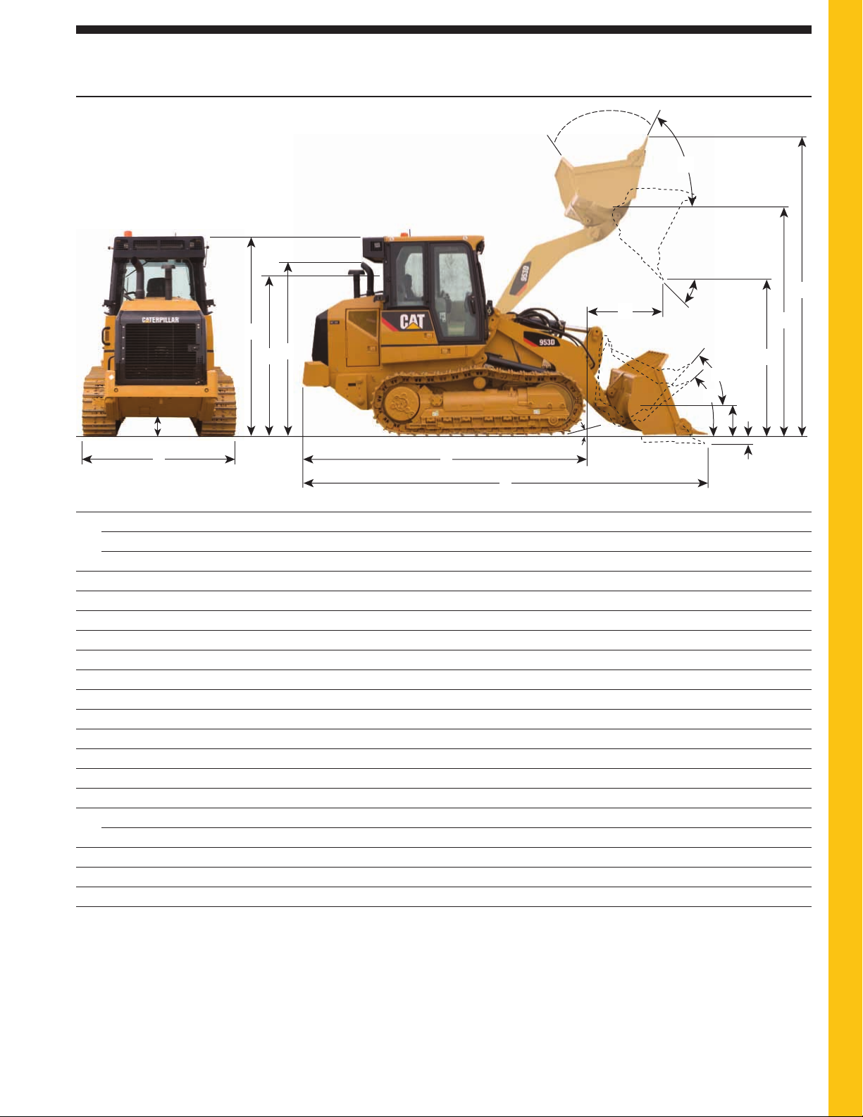
1 Overall machine width without bucket:
with standard tracks – 480 mm (19.7 in shoes) 2280 mm (89.7 in)
with narrow tracks – 380 mm (14.9 in shoes) 2180 mm (85.8 in)
2 Ground clearance 416 mm (16.3 in)
3 Machine height to top of cab 3105 mm (122.2 in)
4 Length to front of track 4363 mm (171.7 in)
5 Overall machine length* 6252 mm (246.1)
6 Carry position approach angle 15°
7 Digging depth* 140 mm (5.5 in)
8 Maximum rollback at ground 41°
9 Maximum rollback at carry position 48°
10 Bucket height in carry position 548 mm (21.6 in)
11 Reach at full lift height and 45° dump* 1195 mm (47 in)
12 Clearance at full lift height and 45° dump* 2694 mm (106 in)
13 Maximum rollback, fully raised 56°
14 Maximum dump, fully raised 55°
Grading angle 74°
15 Height to bucket hinge pin 3610 mm (142.1 in)
16 Overall machine height, bucket fully raised 4882 mm (192.2 in)
17 Height to top of seat with headrest 2560 mm (100.7 in)
18 Height to top of stack 2783.5 mm (109.6 in)
14
16
15
12
9
8
10
7
* With general purpose bucket and extra duty teeth.
Dimensions vary with bucket. Refer to Operating Specifications chart.
Page 22

22
953D Track Loader specifications
Flush
General purpose Multi purpose mounted
bucket bucket teeth
Attachments on Long teeth Bolt-on Long teeth Bolt-on Long
bucket cutting edge None & segments edge None & segments edge teeth
Bucket weight kg 976 1254 1097 1483 1762 1604 1093
lb 2,151.7 2,764.5 2,418.4 3,269.4 3,884.5 3,536.2 2,409.6
Rated load nominal heaped kg 3010 3182 3182 2580 2752 2752 3182
lb 6,635.9 7,015.1 7,015.1 5,687.9 6,067.1 6,067.1 7,015.1
Rated capacity nominal m
3
1.72 1.82 1.82 1.50 1.60 1.60 1.82
heaped (actual) yd
3
2.24 2.38 2.38 1.96 2.09 2.09 2.38
Rated capacity nominal m
3
1.75 1.85 1.85 1.50 1.60 1.60 1.85
heaped (advertised) yd
3
2.28 2.41 2.41 1.96 2.09 2.09 2.41
Struck capacity (actual) m
3
1.48 1.57 1.57 1.27 1.35 1.35 1.48
yd
3
1.93 2.05 2.05 1.66 1.76 1.76 1.93
Struck capacity (advertised) m
3
1.45 1.55 1.55 1.25 1.35 1.35 1.45
yd
3
1.89 2.02 2.02 1.63 1.76 1.76 1.89
Bucket width overall mm 2392 2485 2395 2378 2471 2395 2438
in 94.2 97.8 94.3 93.6 97.3 94.3 95.9
Cutting edge type straight straight straight straight straight straight —
Teeth
none
8 bolt-on with
none none
8 bolt-on with
none
8 bolt-on with
replaceable tips replaceable tips replaceable tips
Dimensions and weights
Overall height mm 3105 3105 3105 3105 3105 3105 3105
in 122.2 122.2 122.2 122.2 122.2 122.2 122.2
Overall operating height mm 4882 4882 4882 4871 4871 4871 4882
in 192.2 192.2 192.2 191.7 191.7 191.7 192.2
Clearance at 45° dump max lift mm 2909 2688 2844 2738 2499 2669 2733
in 114.5 105.8 112.0 107.7 98.3 105 107.6
Reach at 45° dump max lift mm 1002 1197 1042 973 1144 1006 1197
in 39.4 47.1 41 38.3 45 39.6 47.1
Clearance at 45° dump max lift mm 2854 2615 2785
———
2659
in 112.4 103 109.6 104.7
Reach at 45° dump max lift mm 928 1099 961
———
1104
in 36.5 43.3 37.8 43.5
Reach at 45° dump mm 1550 1630 1559 1434 1457 1428 1656
2133 mm (84 in) clearance in 61.1 64.2 61.4 56.5 57.4 56.2 65.2
Bottom dump clearance mm
———
3182 3182 3182
—
at 45° dump max lift in 125.3 125.3 125.3
Bottom dump reach mm
———
559 559 559
—
at 45° dump max lift in 22 22 22
Reach with lift arm horizontal mm 2099 2389 2171 2213 2503 2285 2361
and bucket level in 87 94 85.5 87.1 98.5 89.9 93
Overall length – mm 5926 6252 6017 6077 6401 6167 6198
bucket level on ground in 233.3 246.1 236.9 239.3 252 242.8 244
Digging depth mm 92 140 117 142 190 167 105
in 3.6 5.5 4.6 5.6 7.5 6.6 4.1
Full dump at max lift Deg 55 55 55 49 49 49 55
Full dump at max lift Deg 49 49 49 ———49
Carry height mm 421 421 421 508 508 508 421
in 16.6 16.6 16.6 20 20 20 16.6
Rackback at carry Deg 47 47 47 50 50 50 47
Rackback at ground Deg 41 41 41 42 42 42 41
Grading angle max Deg 74 74 74 74 74 74 74
Static tipping load min kg 11 413 11 089 11 252 10 831 10 492 10 663 11 255
lb 25,162 26,035 24,806 23,878 23,131 23,508 24,813
Breakout with tilt cylinders N 160 549 157 873 159 375 137 216 134 377 135 936 162 579
level at ground lbf 36,093 35,491 35,829 30,847.4 30,209.1 30,559.6 36,549.2
Lift capacity to full lift – kg 5897 5684 5789 5414 5208 5310 5793
bucket racked lb 13,000.6 12,531 12,762.5 11,935.8 11,477.2 11,702.1 12,769.1
Lift capacity at ground line – kg 16 039 15 364 15 694 15 077 14 429 14 744 15 769
bucket racked lb 35,359.9 33,871.7 34,599.3 33,239 31,810.5 32,515.9 34,765
Shipping weight without bucket kg 14 217 14 217 14 217 14 254 14 254 14 254 14 217
lb 31,343 31,343 31,343 31,425 31,425 31,425 31,343
Operating weight with bucket kg 15 577 15 758 15 638 16 302 16 302 16 183 15 635
lb 34,341 34,740 34,476 35,939.7 35,939.7 35,677.4 34,469.3
Operating Specifications
Page 23

23
953D Track Loader specifications
Standard Equipment
Standard equipment may vary. Consult your Caterpillar dealer for details.
POWERTRAIN
Cat®C6.6 ACERT™ engine diesel engine, turbo charged
with ATAAC
Modular cooling system for engine air intake, oil and water
Fan, demand, hydraulically driven
Tank fuel
Electro Hydrostatic Control (EHC) for transmission with
travel and work modes
Fuel priming pump, electric
Water separator
Air inlet, pre-cleaner
Air cleaner dry-type, axial seal with integral pre-cleaner and
dust ejection system, electronic filter condition indicator
Muffler, under hood
Starting aid ether injection
Caterpillar extended-life coolant
Load sensing variable displacement implement pump
UNDERCARRIAGE
Caterpillar SystemOne™ track (38 sec.) 1850 mm
(72.8 in) track gauge
Track, 480 mm (18.9 in), double grouser
Final drive, standard
Track guiding guards, end section
Track adjuster, hydraulic
Sprocket rims, with replaceable bolt-on tough steel segments
Guards, sprocket
7 single flange track rollers per side, with one upper carrier
rollers, lifetime lubricated
Center tread track idlers, lifetime lubricated
Idler, scrapper
Oscillating track roller frames
HYDRAULIC
Oil change
Hydraulic, GP bucket
OTHER STANDARD EQUIPMENT
Caterpillar Product Link 321 (for selected territories)
Tilt cab, locking bar
Sound suppression, exterior
Z-bar loader linkage
Implement cylinders with integrated positioning sensors
Operator programmable lift and tilt kickouts
Engine enclosure with lockable doors
Radiator core 6.5 fpi, debris resistant
Hinged Radiator Guard and swing out fan
Guards, full bottom
Bumper
Ecology drains on hydraulic tank
Product link ready
Oil sampling valves
Hoses, Caterpillar XT
Warning decals
Hydraulic Oil, HYDO Advanced 10
ELECTRICAL
Alternator, 24 volt, heavy duty brushless.
Alarm, backup
Horn, electric
2 heavy duty batteries, high output, maintenance free,
950 CCA
Switch, Main disconnect
Starter, Electric (heavy duty, 24 volt)
Four halogen lights, two forward facing, roof mounted;
two facing rearward integrated in A/C unit
OPERATOR ENVIRONMENT
Cat Messenger
Side sliding windows
Pressurized, sound suppressed, ROPS/FOPS cab with
tinted glass and sliding side windows
Air conditioning and heating
Heater/defroster with automatic temperature control
Seat, air suspended adjustable, with side-to-side isolator
Electro Hydraulic seat mounted control levers
Seat belt, retractable
Electronic Monitoring System with gauges for:
Engine coolant temperature
Hydraulic oil temperature
Pump drive box oil temperature
Fuel level
Mirror, rearview, inside
Radio ready. Includes 24 to 12 volt converter, speakers,
antenna and one 12 volt power outlets
Coat hook
Transmission control, V-lever
or Transmission control, Joystick
Control, joystick, bucket gp
Storage compartments under left armrest
Document holder on right console
Floor mat, rubber, heavy duty
Windshield washers and wipers, front and rear
Cab window, front glued
Durable metal roof
Parking brake switch and “brake-on” indicator light
Page 24

24
953D Track Loader specifications
Optional Equipment
Optional equipment may vary. Consult your Caterpillar dealer for details.
BUCKET ATTACHMENTS
Teeth, Extra Duty
Teeth, General Duty
Teeth, Penetration
Bolt On, Cutting Edge
Bolt On Segments, Cutting Edge
Cutting Edge Segment
Tips, Extra Duty
GUARDS
Guard, track roller
Guard, idler
Guard, cab lights
Guard, lift lines
Screen, windshield
UNDERCARRIAGE
Track shoes, 380 mm (15 in), double grouser
Track shoes, 380 mm (15 in), triple grouser
Track shoes, 480 mm (18.9 in), center hole
Final drive, waste
OTHER ATTACHMENTS
Shovel holder
Cab, tilt jack, hydraulic
Radio, AM/FM, CD
Heather, engine coolant, 120V
Heather, engine coolant, 240V
Re-fueling pump
Sediment pump, fuel tank
Antifreeze, –50° C (–58° F)
ELECTRICAL
Lights, 4, extra
Beacon, rotating
OPERATOR ENVIRONMENT
Control, joystick, MP bucket
Control, two levers, GP bucket
Comfort seat, air suspended, heated
Cab window, front sealed
Messenger, full text diagnostics and monitoring system
POWER TRAIN
Fan, demand, reversible
Tank fuel, fast fill
Air inlet, pre-cleaner, turbine
HYDRAULICS
Hydraulic oil, bio
Oil change, high speed
Hydraulics MP Bucket, lines front
Hydraulics RIPPER, control, lines rear
Hydraulics MP + RIPPER, lines front and rear
REAR ATTACHMENT
Striker bar, rear
Ripper, multi-Shank
Hitch, standard
Hitch, extended
Counterweight, light
Counterweight, additional
BUCKETS
General Purpose, for bolt-on GET
General Purpose, flush mounted adapt
Multi-Purpose
Multi-Purpose, landfill
General Purpose, landfill, flush mounted adapt
General Purpose, landfill and demolition
Page 25

953D Track Loader specifications
25
Notes
Page 26

953D Track Loader specifications
26
Notes
Page 27

953D Track Loader specifications
27
Notes
Page 28

For more complete information on Cat products, dealer services,
and industry solutions, visit us on the web at www.cat.com
© 2008 Caterpillar
All Rights Reserved
Printed in U.S.A.
Materials and specifications are subject to change without notice.
Featured machines in photos may include additional equipment.
See your Caterpillar dealer for available options.
CAT, CATERPILLAR, ACERT, SystemOne, SAFETY.CAT.COM, their respective logos,
“Caterpillar Yellow,” and the POWER EDGE trade dress, as well as corporate and product
identity used herein, are trademarks of Caterpillar and may not be used without permission.
AEHQ5826-02 (9-08)
Replaces AEHQ5826-01
953D Track Loader
R
 Loading...