

Page 1
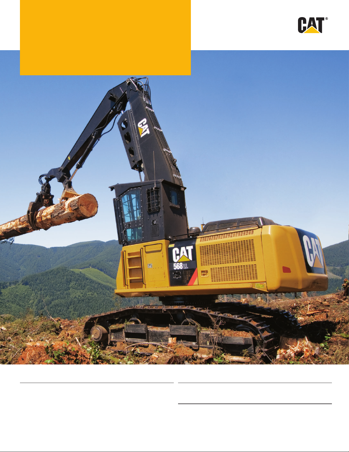
568
Forest Machine
Engine Drive
Engine Model Cat
Gross Power 238 kW 319 hp Maximum Drawbar Pull 317 kN 71,264 lbf
Rated Power 221 kW 296 hp Weight*
Rated Speed 1,800 rpm General Forestry 43 184 kg 95,204 lb
®
C9.3 (ATAAC) Maximum Travel Speed 4.8 km/h 3 mph
Log Loader (U/U) 48 139 kg 106,128 lb
Log Loader (U/O) 48 298 kg 106,479 lb
*Operating weight with front linkage, without bucket or grapple.
Page 2
Introduction
Cat® forest machines are versatile, purpose-built
machines that can be customized to perform many
forestry applications.
Since its introduction in the 1990s, the 300 Series
family of forest machines has become the industry
standard in many logging industry applications.
The all-new 500 Series will continue that
trendsetting standard.
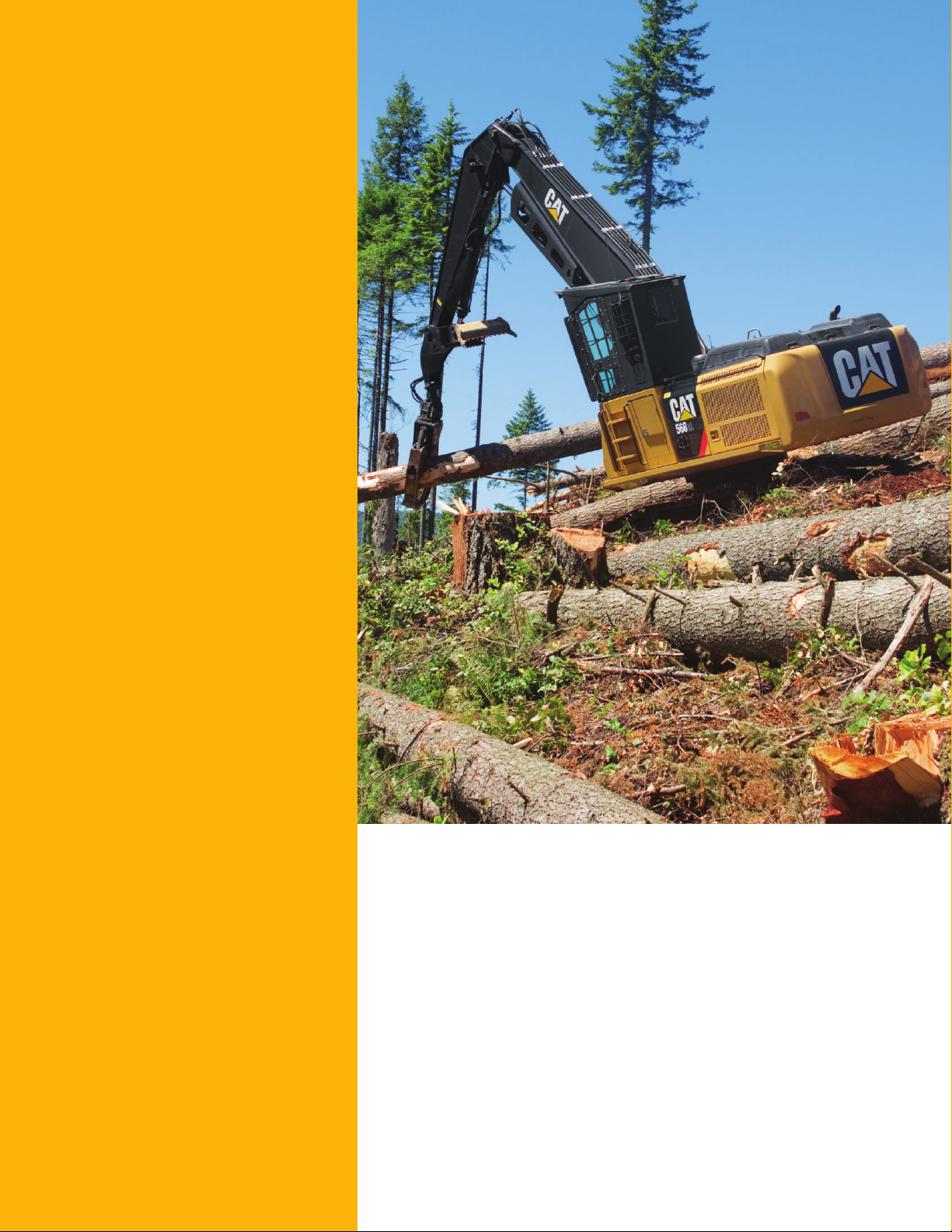
The rst model in the new family, the 568, meets
today’s U.S. EPA Tier 4 Interim emissions standards.
The 568 features increased horsepower, more
ef cient hydraulics, longer track frames for
morestability, and ground-level accessibility
formaintenance.
It is available in a general forestry con guration
for road building, site prep and processing;
and in a loader version for log loading, shoveling,
butt-n-top loading and millyard applications.
Contents
Hydraulics ............................................................3
Operator Station..................................................4
Engine ...................................................................5
Structures and Undercarriage .........................6
Front Linkage .......................................................7
Work Tools ............................................................8
Integrated Technologies ..................................10
Serviceability .....................................................11
Safety ..................................................................12
Complete Customer Care.................................13
Sustainability .....................................................14
568 Speci cations .............................................15
568 Standard Equipment ..................................23
568 Mandatory Attachments...........................24
568 Optional Equipment....................................25
2
Page 3
Hydraulics
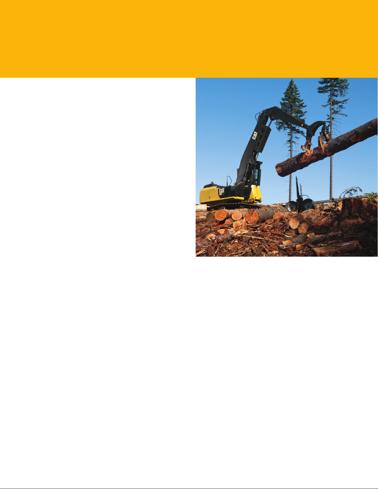
Power to move more trees, dirt, and most forest debris with speed and precision
Hydraulic Horsepower
Hydraulic horsepower is the actual machine power available
to do work through implements and work tools. It’s much
more than just the engine power under the hood – it’s a core
strength that differentiates Cat® machines from other brands.
In fact, hydraulic horsepower for the 568 increased from
the previous series’ output due to pump and other system
improvements. This translates into moving more material
inless time.
Main Control Valve and Auxiliary Valves
The 568 uses a high-pressure system to tackle the toughest
of work in short order. A new one-piece, cast-block, backto-back main control valve features resized and reshaped oil
passages to improve efciency and serviceability; stackable
auxiliary valve attachments mount on top of the main
valve, which allows for auxiliary hydraulic lines and valve
congurations to be simplied for greater reliability.
Return Filter
The return lter is a capsule-type design with a cartridge
inside. Unlike many competitors’ offerings, the Cat cartridge
features a handle to help remove and change without oil
spillage or contamination. A sensor attached to the lter warns
the operator if it is plugging or exceeds a certain pressure level.
Swing Priority Circuit
The swing priority circuit on the 568 uses a new electric valve
that’s operated by the machine’s improved Electronic Control
Module (ECM). Compared to using a hydraulic valve, an
electric valve allows for more nely tuned control, which is
critical during material loading.
Electric Boom Regeneration Valve
A new electric boom regeneration valve minimizes pump ow
when the boom lowers down, which improves fuel economy.
It is optimized for any dial speed setting being used by the
operator, which in turn aids controllability and enhances
component durability.
Stick Regeneration Circuit
The 568 regenerates the ow of oil from the rod end of
thestick cylinder to the head end of the stick cylinder during
low-load, stick-in operation – an approach that saves energy
and expense.
3
Page 4
Operator Station
Comfort and convenience to keep people productive
Seats
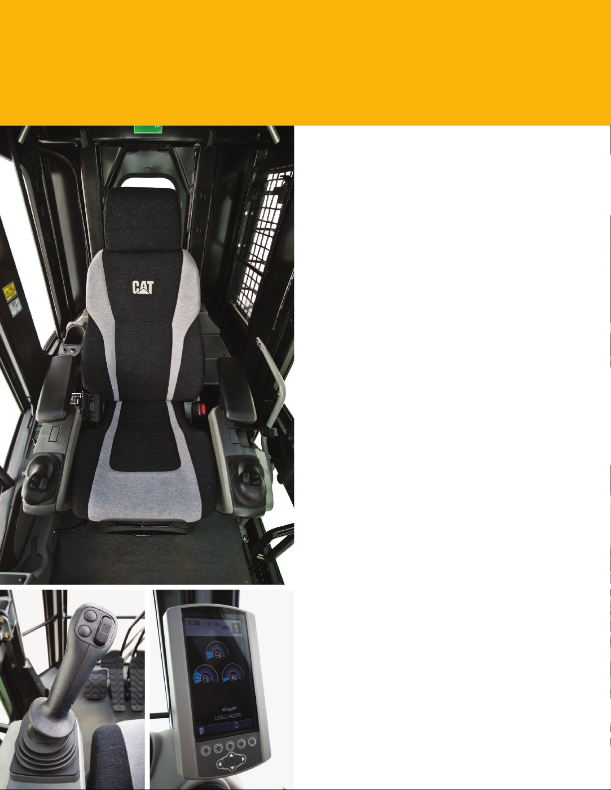
A new seat range includes air suspension, heated standard,
and heated and air cooled option. Each seat includes a
reclining back, upper and lower seat slide adjustments,
andheight and tilt angle adjustments to meet operator
needsfor comfort and productivity.
Controls
The right and left joystick consoles can be adjusted to meet
the operator’s desired preference, making him (or her) more
comfortable and productive during the course of a day.
With the touch of the button, one-touch idle reduces engine
speed to help save fuel; touch itagain or move the joystick
andthe machine returns to normal operating level.
The optional heavy lift mode increases machine system
pressure to improve lift – a nice benet in certain situations.
Heavy lift mode also reduces engine speed and pump ow in
order to improve controllability.
Monitor
The 568 is equipped with a new LCD (Liquid Crystal
Display) monitor that’s 40% bigger than the previous model’s
with higher resolution for better visibility. Inadditionto an
improved keypad and added functionality, it is programmable
to provide information in a choice of 42languages to support
today’s diverse workforce.
A new “Engine Shutdown Setting” accessible through the
monitor allows owners and operators to specify how long the
machine should idle before shutting down the engine, which
can save signicant amounts of fuel.
MP3-Ready Radio and Power Supply
The standard radio is equipped with a new auxiliary audio
port for MP3 players. Two 12-volt power supply sockets are
located near key storage areas for charging.
Storage
Storage spaces are provided to the front and rear of the
right-side console to hold small items.
Automatic Climate Control
An updated climate control system helps provide a comfortable
working environment in the 568. Improved AC ducting
provides increased airow and operator comfort. A standard
sun screen provides reduced sun glare and heat build up in cab.
4
Page 5
Engine
Reduced emissions, economical and reliable performance
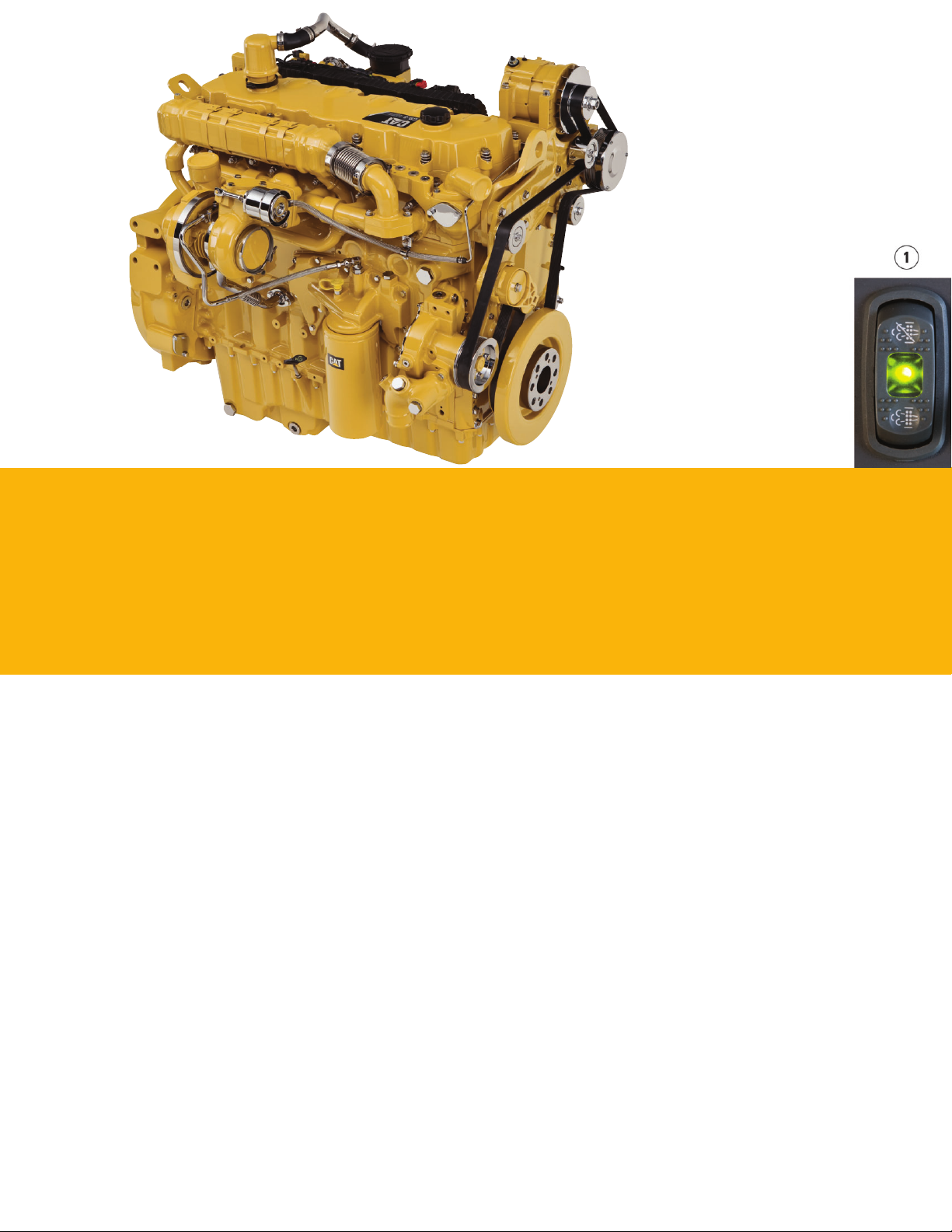
Cat® C9.3 ACERT™ Engine
The C9.3 ACERT engine delivers more horsepower using less fuel than the previous series engine.
Emissions Solution
The C9.3 ACERT engine is equipped to meet current Tier 4 Interim emissions standards. Driven by customer input,
Cataftertreatment regeneration solution ensures the machine works as normal with no operator intervention needed.
The machine comes with two programmable modes of operation: automatic and manual regeneration.
In automatic mode, the machine starts the regeneration process once the ltering system reaches a certain level and conditions
are optimal. The system will not interrupt the work process and can regenerate during machine operation.
Manual mode enables the operator to override the automatic mode. With a touch of a button (1) inside the cab, this mode
allows the operator to move the machine from sensitive work areas before initiating the regeneration process.
Bio Diesel-Ready Fuel System
The C9.3 ACERT engine is equipped with a high-pressure common rail fuel system that includes a new electric priming pump
and three-layer fuel hose to allow the use of bio fuel up to B20 (bio fuel 20% mixture).
Cooling System
The high-ambient cooling system features side-by-side-mounted radiator and oil and air coolers for easy cleaning and a new
Flexxaire variable pitch, auto reversing fan for enhanced energy efciency as standard equipment.
Speed and Power Control
The new 568 features isochronous speed control to maintain a constant speed – regardless of load – to improve fuel economy.
Three different power modes are offered: high power, standard power, and economy power. The operator can easily change
between modes through the monitor or console switch to meet the needs for the job at hand – all to help manage and conservefuel.
5
Page 6
Structures and Undercarriage
Built to work in rugged forestry environments
Frame
The upper frame includes new reinforced mountings to support the Roll-Over Protective Structure
(ROPS) cab; the lower frame is reinforced to increase component durability.
Undercarriage
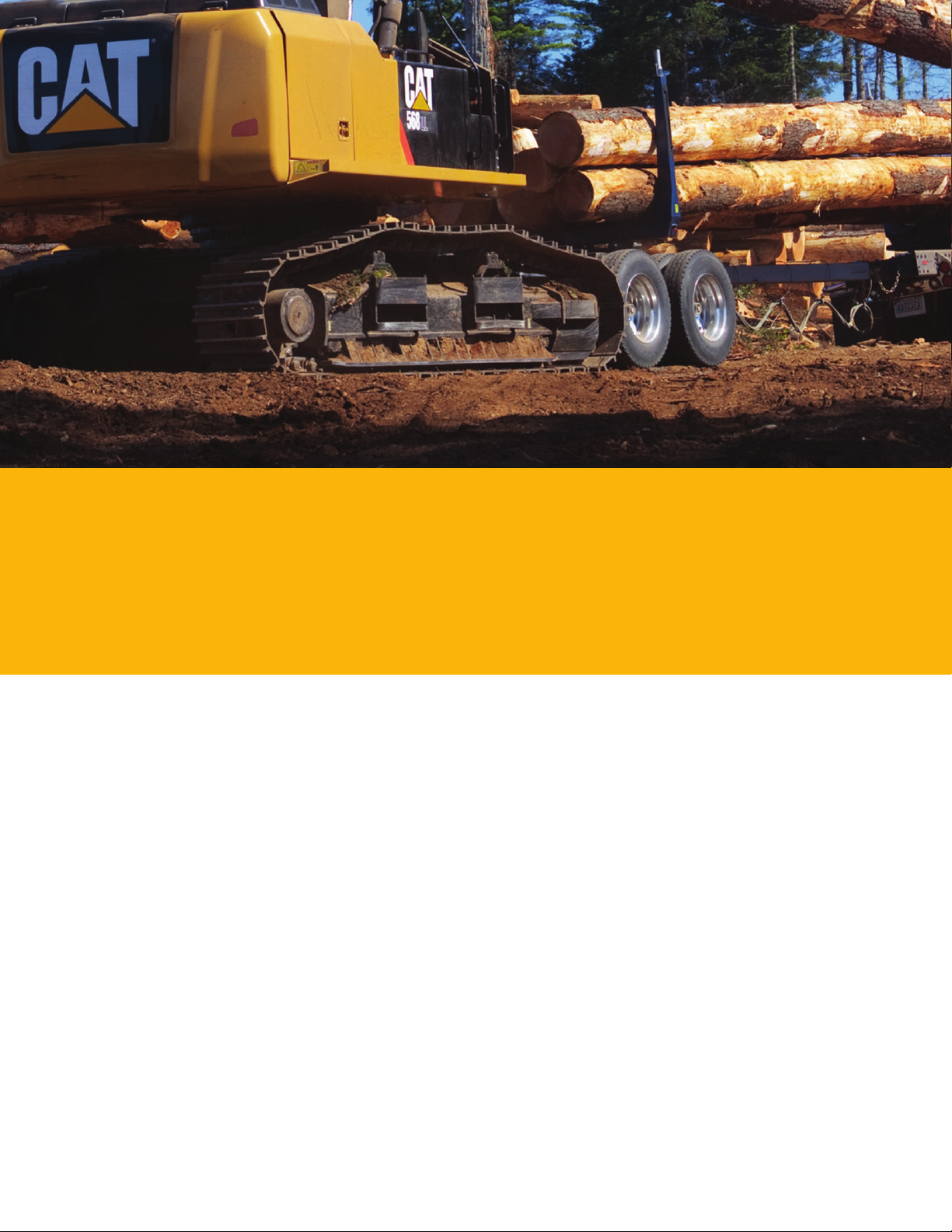
A longer undercarriage system provides added stability in the most demanding applications.
Heavy-duty track rollers, and carrier rollers, press-t pin master joints, and enhanced track shoe
bolts improve durability and reduce the risk of machine downtime and the need and cost toreplace
components.
A new full length guiding guard maintains track alignment and improves performance and
undercarriage life in multiple applications.
A redesigned motor housing prevents mudpacking and debris buildup around seals.
Counterweights
Two counterweight options are available for General Forestry: 6.0 MT and 8.3 MT. The 8.3 MT
counterweight is standard on the Log Loader conguration. Eachis designed to match the height
ofthemachine, and each comes with new integrated links that enable easy removal for maintenance.
Regardless of choice, counterweights are bolted directly to the main frame using four M36 bolts
forrigidity.
6
Page 7
Front Linkage
Made for high stress and long service life
Booms, Sticks and Heels
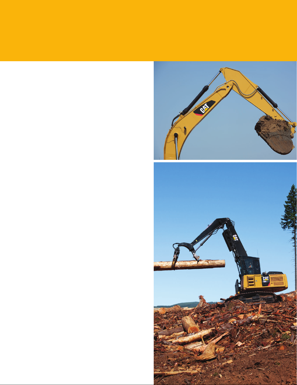
The 568 offers both General Forestry and Log Loader
booms and sticks. Eachis built with internal baf e plates
foradded durability, quality and reliability. Large box-section
structures with thick, multi-plate fabrications, castings, and
forgings are used in high-stress areas to improve durability.
Selections
There are two General Forestry, two Log Loader boom and
stick, and three heel options available to match a variety
of forestry applications. There is also a DB-Family Bucket
Linkage available for the General Forestry con gurations.
Reach. This type of boom is best used for applications
whereadded reach above and below ground level are
required. The combination of boom and stick is matched
tothese conditions.
Mass. This type of boom is best used fordemanding
applications. The Mass front provides higher digging forces
due to the geometry of the boom and stick. Bucket linkage
and cylinders are more durable for excellent productivity
inharsh applications.
Log Loader – Under/Under (U/U). This type of boom and stick
are best suited for shovel logging and loading applications.
The under mounted heel cylinder provides maximum heeling
force for heavy shovel logging conditions. This U/U stick
canalso be re-congured for use with a Butt-n-Top or Power
Clam style attachment.
Log Loader – Over/Under (O/U). This type of boom and stick
are best suited for loading and millyard applications. The over
mounted heel cylinder and increased reach provide maximum
clearance to load and maximize the lift height for millyard
orloading conditions.
Heel. Heels are available in U/U, O/U and U/U Offset
congurations to match the requirements of log loader
application linkage needs.
7
Page 8
Work Tools
Grapple, Dig, and Thumb with con dence
Work Tools
An extensive range of tools can be t up to the 568 includes
grapples, buckets and thumbs. Each is designed to optimize
the versatility and performance of your machine.
Hydraulic
A thumb control group can be t up to the General Forestry,
and Butt-n-Top and Power Clam hydraulics can be installed
onthe Log Loader.
Several different boom and stick line groups are available
as options on the 568 for running various work tool
attachments.
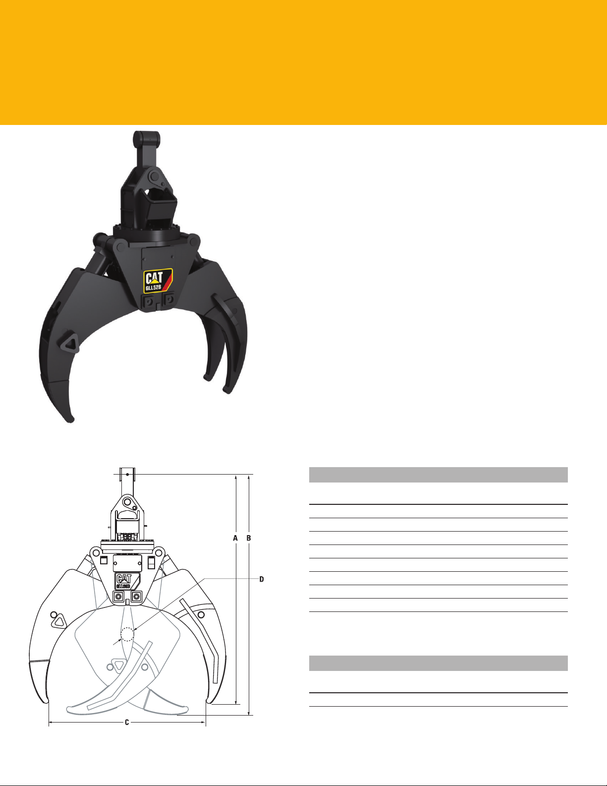
GLL Logging Grapples
The Cat brand offers a complete line of shovel and loading
grapples. These are available in 52", 55" and 60" sizes to meet
a range of application requirements.
GLL Specifications/Dimensions
GLL52B GLL55B GLL60B
Weight (kg/lb)
Width (mm/in)
A Height, open (mm/in)
B Height, closed (mm/in)
C Maximum Opening (mm/in)
D Minimum Opening (mm/in)
Rotation, continuous
Rotation torque at 1,200 psi
(N·m/ft lb)
1255/2,767 1291/2,840 1344/2,965
1725/68 1765/70 1935/76
2134/84 2184/86 2261/89
2159/85 2210/87 2286/90
1321/52 1397/55 1524/60
127/5 127/5 127/5
360° 360° 360°
1153/850 1153/850 1153/850
Matching Guide
GLL52B GLL55B GLL60B
568
Provides optimum machine match.
f
Provides acceptable machine match.
*
8
* f f
Page 9
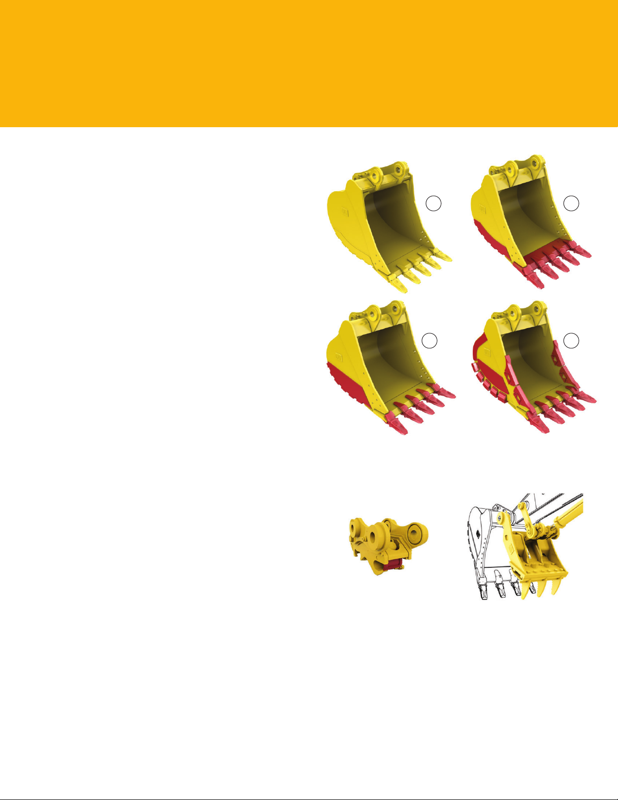
Buckets
Cat buckets are designed for better performance. The leading
edge has been pushed forward, resulting in more ef cient
lling and better operator control for greatly improved
productivity.
Wear coverage in the corners and side cutter and sidebar
protector coverage are improved; a new lift eye design accepts
a wide range of shackle sizes.
Couplers
Quick couplers allow one person to change work tools in
seconds for maximum performance and exibility on a job
site. One machine can move rapidly from task to task, and
a eet of similarly equipped machines can share a common
work tool inventory.
1 2
3 4
1) General Duty 2) Heavy Duty 3) Severe Duty 4) Extreme Duty
9
Page 10
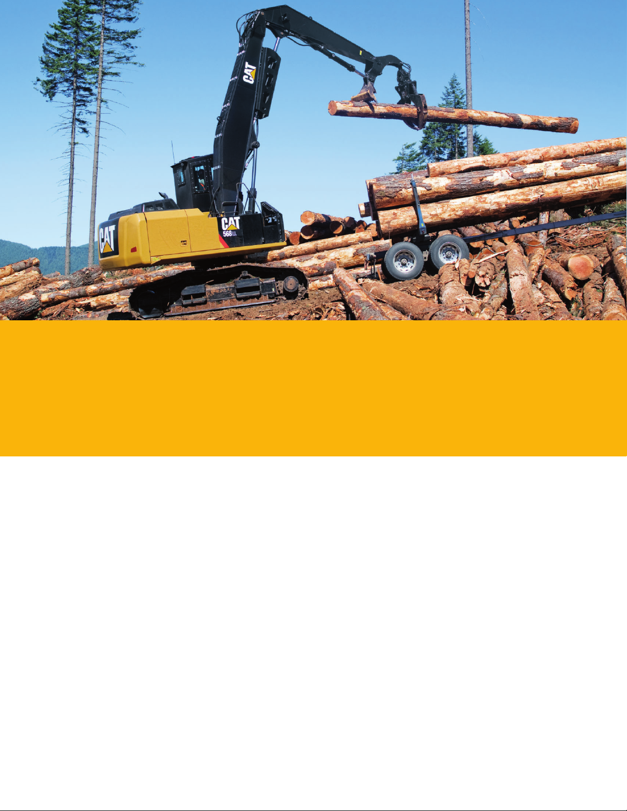
Integrated Technologies
Solutions that make work easier and more ef cient
Electric Boom and Stick Regeneration Valve
The 568 features unique electric boom and stick regeneration valves. The valves use gravity during
typical “boom down” or “stick in” operations to regenerate ow of oil from the head end of the cylinder
to the rod end of the cylinder instead of sending it all the way back to the hydraulic tank. This distinct
Cat solution increases efciency and reduces cycle times and pressure loss for higher productivity and
lower fuel costs.
Main Control Valve
The 568 uses a high pressure hydraulic system as standard. It is a one-piece, cast-block, back-to-back (BTB)
control valve, improving efciency and serviceability versus the previous series machines. Auxiliary valves
are stackable and mounted on top of the main valve, which simplies, and leads to greater reliability.
Fuel consumption is reduced by re-sizing and shaping of the oil passages inside the new BTB valve.
Flexxaire Auto-Reversing Fan
The cooling system’s new variable pitch reversible fan is controlled by hydraulic temperature, coolant
temperature, and ATAAC charge air temperature in different ambient conditions to optimize cooling.
The fan has a pitch sensor that is controlled by the Electronic Control Module (ECM).
Cat Product Link*
This deeply integrated machine monitoring system is designed to help customers improve their overall
eet management effectiveness. Events and diagnostic codes as well as hours, fuel consumption, idle time,
machine location, and other detailed information are transmitted to a secure web based application called
VisionLink™, which uses powerful tools to communicate to users and dealers.
*Product Link licensing is not available in all areas. Please consult your Cat dealer for availability.
10
Page 11
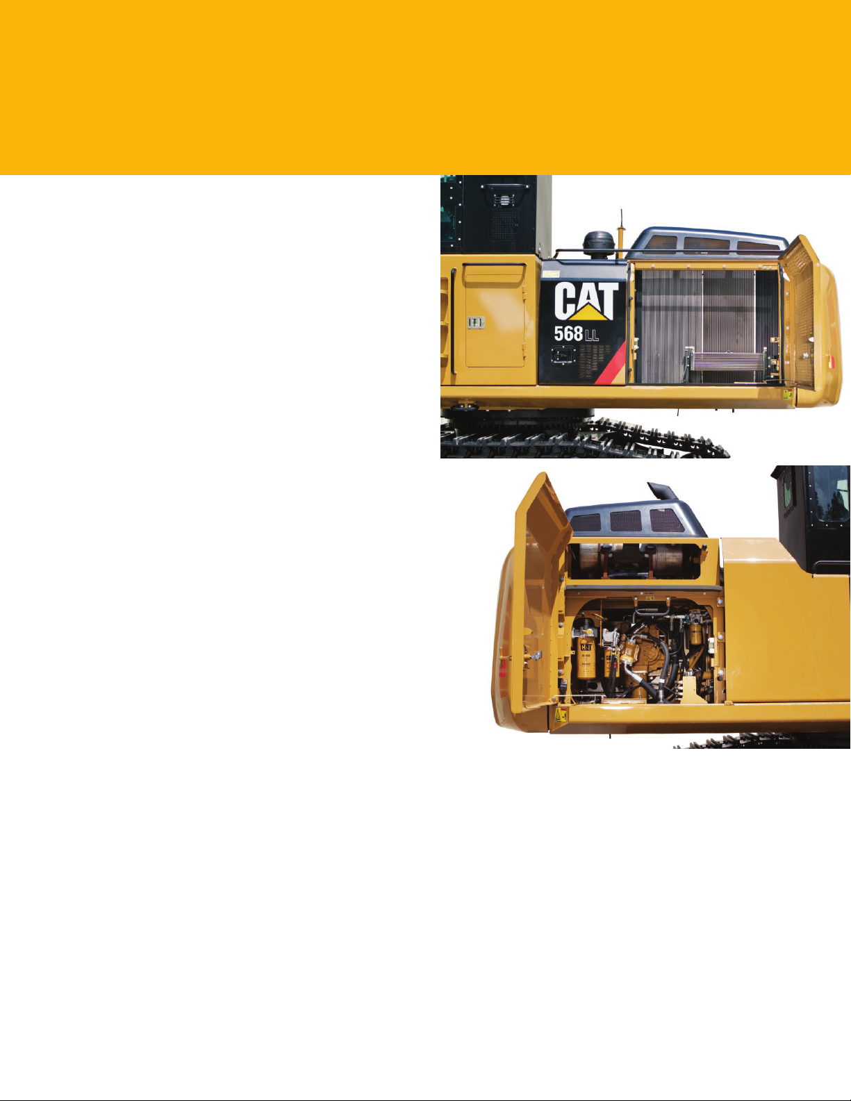
Serviceability
Fast, easy and safe access built in
Ground-Level Maintenance
The machine is designed to accommodate servicing most
maintenance items from the safety and comfort of ground level.
Service Doors
Wider, taller service doors feature sturdier hinges and latches
and a new slotted hole vent design to prevent debris entry;
anewone-piece hood provides easier access to the engine
andcooling compartments along with a new hood screen
design to prevent debris entry.
Compartments
The radiator, pump, and air cleaner compartments provide
easy access to major components. When an air cleaner plugs,
a warning is displayed on the monitor inside thecab.
Other Service Improvements
The water separator with water level sensor has a primary
fuel lter element located in the pump compartment near
ground level; the electric priming pump is mounted on the
primary lter base and is more reliable and easier to service
than traditional hand-priming pumps.
The engine oil check gauge is situated in front of the
engine compartment and is easy to remove. The engine oil
lter issituated in the pump compartment for easy access.
Changing engine oil is simple due to a drain cock designed
toprevent spills.
The 568 has two fuel tanks as standard equipment, reducing
rell intervals. Drain cocks are provided to make it easy to
remove water and sediment during maintenance.
11
Page 12
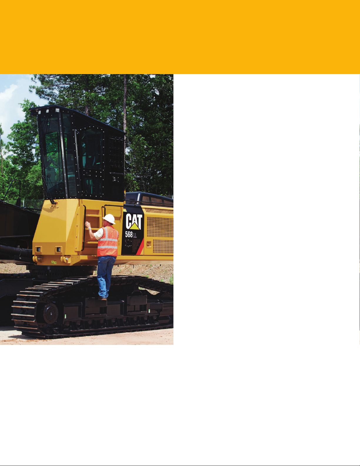
Safety
Features to help protect people
Reinforced Frame
The upper frame is reinforced to accommodate the ROPScab.
Sound Proong
Improved sealing and cab roof lining help lower noise levels
during machine operation.
Anti-Skid Plates
The surface of the upper structure and the top of fuel tank
area are covered with anti-skid plates to help prevent service
personnel and operators from slipping during maintenance.
Steps, Hand and Guard Rails
Steps on the track frame and storage box along with
extended hand and guard rails to the upper deck enable
operators to work securely on the machine.
Operator Cab
The 568 is equipped with a new forestry cab that is certi ed to:
• OPS – ISO 8083 and SAE J231
• FOPS – ISO 8084 and SAE 1084
• FOGS – SAE J1356
• ROPS – ISO 3471:1997
Table 1, Section 1
• TOPS – OR-OSHA code 437-007-0775
• WCB G602/G603/G604/G608 compliant
12
Windshield Wipers
The 568 offers parallel type windshield wipers with
both continuous and intermittent modes to t varied
precipitationlevels.
Monitor Warning System
The monitor is equipped with a buzzer that can warn an
operator of critical events like “Engine Oil Pressure Decrease,”
“Coolant Temperature High” or “Hydraulic Oil Temperature
High,” allowing for immediate action to take place.
Page 13

Complete Customer Care
Service you can count on
Product Support
Cat dealers utilize a worldwide parts network to minimize machine downtime. Plus you can save money
with Cat remanufactured components.
Machine Selection
Make detailed comparisons of machines you are considering. What are the job requirements and
machine attachments? What production is needed? Your Cat dealer can provide recommendations.
Purchase
Consider nancing options and day-to-day operating costs. Look at dealer services that can be included
in the machine’s cost to yield lower owning and operating costs over time.
Customer Support Agreements
Cat dealers offer a variety of customer support agreements and work with you to develop a plan to
meetspecic needs. These plans can cover the entire machine, including attachments, to help protect
your investment.
Operation
Improving operating techniques can boost your prots. Your Cat dealer has videos, literature, and other
ideas to help you increase productivity. Caterpillar also offers simulators and certied operator training
to help maximize the return on your investment.
Replacement
Repair, rebuild, or replace? Your Cat dealer can help you evaluate the cost involved so you can make
theright choice.
13
Page 14
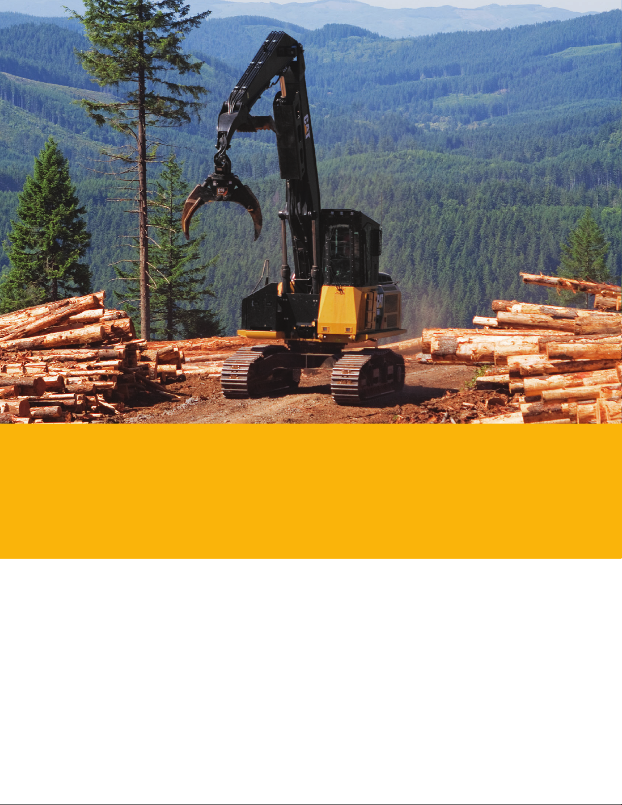
Sustainability
Generations ahead in every way
• The C9.3 ACERT engine, along with the Cat Clean Emissions Module (CEM), meets U.S. EPA
Tier 4 Interim, emissions standards.
• The 568 generates more horsepower, lifts more payload, and burns less fuel than the previous
seriesmachine, which means more efciency and productivity with less resource consumption
andfewer CO2 emissions.
• The 568 has the exibility of running on either ultra-low-sulfur diesel (ULSD) fuel with 15 ppm
ofsulfur or less or bio diesel (B20) fuel blended with ULSD.
• The 568 is equipped with one-touch idle to reduce engine speed quickly and conveniently
conserving fuel.
• The 568 is built to be rebuilt with major structures and components remanufactured to reduce
waste andreplacement costs.
• The 568 is an efcient, productive machine that’s designed to conserve our natural resources for
generations ahead.
14
Page 15

568 Forest Machine Speci cations
Engine Hydraulic System
Engine Model Cat® C9.3 (ATAAC) Pilot System – 26 6.87
Gross Power 238 kW 319 hp
Rated Power 221 kW 296 hp
Rated Speed 1,800 rpm
Displacement 9.3 L 567.5 in
Maximum Torque 1426 1,051.7
N·m lb ft
Number of Cylinders 6
Bore 115 mm 4.53 in
Stroke 149 mm 5.87 in
Weights
Estimated Operating Weight
withoutAttachment
General Forestry 43 184 kg 95,204 lb
Log Loader (U/U) 48 139 kg 106,128 lb
Log Loader (O/U) 48 298 kg 106,478 lb
Operating Specifications
Maximum Speed 4.8 km/h 3 mph
High Range
Maximum 317 kN 71,264 lb
DrawbarPull
Swing Torque – 113.9 84,024
General Forestry kN·m lb ft
Swing Torque – 148.5 109,560
LogLoader kN·m lb ft
Maximum Swing 10 rpm
Speed – General
Forestry
Maximum Swing 6.3 rpm
Speed – Log Loader
Operator Height from Ground (eye level)
General Forestry 3.4 m 135 in
Cab 0.48 m (18 in)
Riser
Log Loader Cab 4.2 m 165 in
1.2 m (48 in) Riser
Maximum Flow L/min gal/min
Pilot System – 4100 kPa 595 psi
Maximum Pressure
Main Pump System – 289 76.3
3
Maximum Flow (2x) L/min gal/min
Maximum Pressure – 35 000 kPa 5,076 psi
Implements
Maximum Pressure – 28 000 kPa 4,061 psi
Swing (single)
Maximum Pressure – 31 400 kPa 4,550 psi
Swing (dual)
Auxiliary Pump
Maximum Flow – 51 13.5
Factory Setting L/min gal/min
Maximum Flow – 108 28.5
Capacity L/min gal/min
Maximum Pressure– 10 350 kPa 1,500 psi
Factory Setting
Maximum Pressure– 25 000 kPa 3,626 psi
Capacity
General Forestry
Boom Cylinder – 150 mm 5.9 in
Bore
Boom Cylinder – 1440 mm 56.7 in
Stroke
Stick Cylinder – 170 mm 6.7 in
Bore
Stick Cylinder – 1738 mm 68.4 in
Stroke
Bucket Cylinder – 150 mm 5.9 in
Bore
Bucket Cylinder – 1151 mm 45.3 in
Stroke
Log Loader
Boom Cylinder – 170 mm 6.7 in
Bore
Boom Cylinder – 1340 mm 52.8 in
Stroke
Stick Cylinder – 180 mm 7.1 in
Bore
Stick Cylinder – 1661 mm 65.4 in
Stroke
Bottom Heel 150 mm 5.9 in
Cylinder – Bore
Bottom Heel 1155 mm 45.5 in
Cylinder – Stroke
Top Heel 160 mm 6.3 in
Cylinder– Bore
Top Heel 1465 mm 57.7 in
Cylinder– Stroke
Drive
Maximum 4.8 km/h 3 mph
TravelSpeed
Maximum 317 kN 71,264 lbf
DrawbarPull
Service Refill Capacities
Fuel Tank 1200 L 317 gal
Capacity– Total
Fuel Tank 620 L 163.8 gal
Capacity– Main
Fuel Tank 580 L 153.2 gal
Capacity– RF
Final Drive – Each 8 L 2.1 gal
Cooling System 56 L 14.8 gal
Engine Oil 30.5 L 8.1 gal
Hydraulic Tank 175 L 46.2 gal
Hydraulic System – 380 L 100.4 gal
Total
Swing Drive 20 L 5.3 gal
(LogLoader 2x)
Swing Drive 19 L 5 gal
(General Forestry)
15
Page 16

568 Forest Machine Speci cations
Track Undercarriage Standards
Number of Shoes 52 Undercarriage Size 345HD Brakes ISO 10265:1998
(each side)
Number of Track Rollers
(eachside)
Number of Carrier Rollers
(eachside)
10
2
Undercarriage Pitch 215.9 mm 8.5 in
Track Gauge
Track Length
Ground Clearance
2920 mm 115 in
5390 mm 212 in
760 mm 30 in
ROPS/FOPS/
OPS/TOPS
ISO 11512:1995
ISO 8083:1989 LEVEL I
ISO 8083:1989 LEVEL II
SAE J/1084 FEB 1978,
ISO8084:1993
SAE J/1356 FEB 1988,
WCB G602, G603,
G604,G608
ISO 3471:1997 (TABLE 1,
SECTION 1)
OR-OSHA 437-007-0775(14)
16
Page 17

Dimensions
All dimensions are approximate.
4 4
2
1
2
6 6
7 7
4
1
2
5
3
3
8 8
6
7
Height – General Forestry – Cab tilted 3520 mm 138.6 in
1
Height – Log Loader – Cab tilted 3520 mm 138.6 in
Boom Height – General Forestry – Shipping 3520 mm 138.6 in
2
Boom Height – Log Loader – Shipping 4954 mm 195 in
Height – General Forestry (overall) 4190 mm 165 in
3
Height – Log Loader (overall) 4954 mm 195 in
Shipping Length – General Forestry (Mass) 10 780 mm 424.4 in
4
Shipping Length – General Forestry (Reach) 11 120 mm 437.8 in
Shipping Length Log Loader (U/U) 16 610 mm 653.9 in
Shipping Length Log Loader (O/U) 17 082 mm 672.5 in
Tail Swing Radius 3460 mm 136.2 in
5
Track Length – Idler to Sprocket 4356 mm 171.5 in
6
Track Length – Total 5390 mm 212.2 in
7
Ground Clearance 760 mm 30 in
8
Track Gauge 2920 mm 115 in
9
Overall Width with 700 mm (27.5 in) Shoes 3650 mm 143.7 in
10
9 9
10 10
17
Page 18
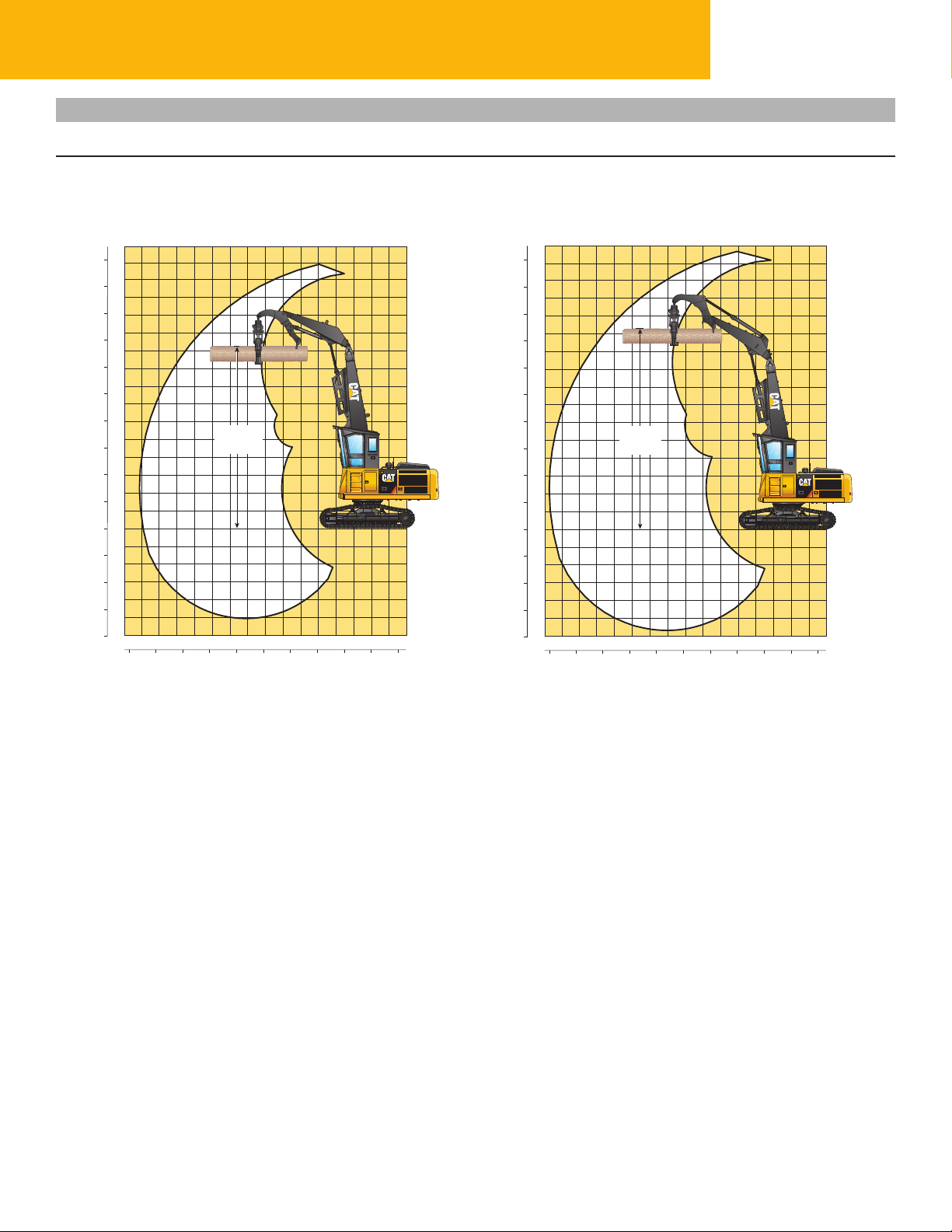
568 Forest Machine Speci cations
Working Ranges
Heel Boom, Under/Under and Over/Under Ranges
Heel Boom Heel Boom
(Under/Under) (Over/Under)
Meters
Feet
50
15
14
45
13
40
12
11
35
10
30
9
8
25
7
20
6
5
15
4
10
3
2
5
1
0
0
1
5
2
3
10
4
15
5
6
20
13 12 11 10 9
45 40 35 30 25 20 15 10 5 0 -5
MAXIMUM
LEVEL
LOG HEIGHT
87 6 5 4
321 0 -1
Meters
Feet
Meters
Feet
50
15
14
45
13
40
12
11
35
10
30
9
8
25
7
20
6
5
15
4
10
3
2
5
1
0
0
1
5
2
3
10
4
15
5
6
20
13 12 11 10 9
45 40 35 30 25 20 15 10 5 0 -5
MAXIMUM
LEVEL
LOG HEIGHT
87 6 5 4
321 0 -1
Meters
Feet
18
Page 19
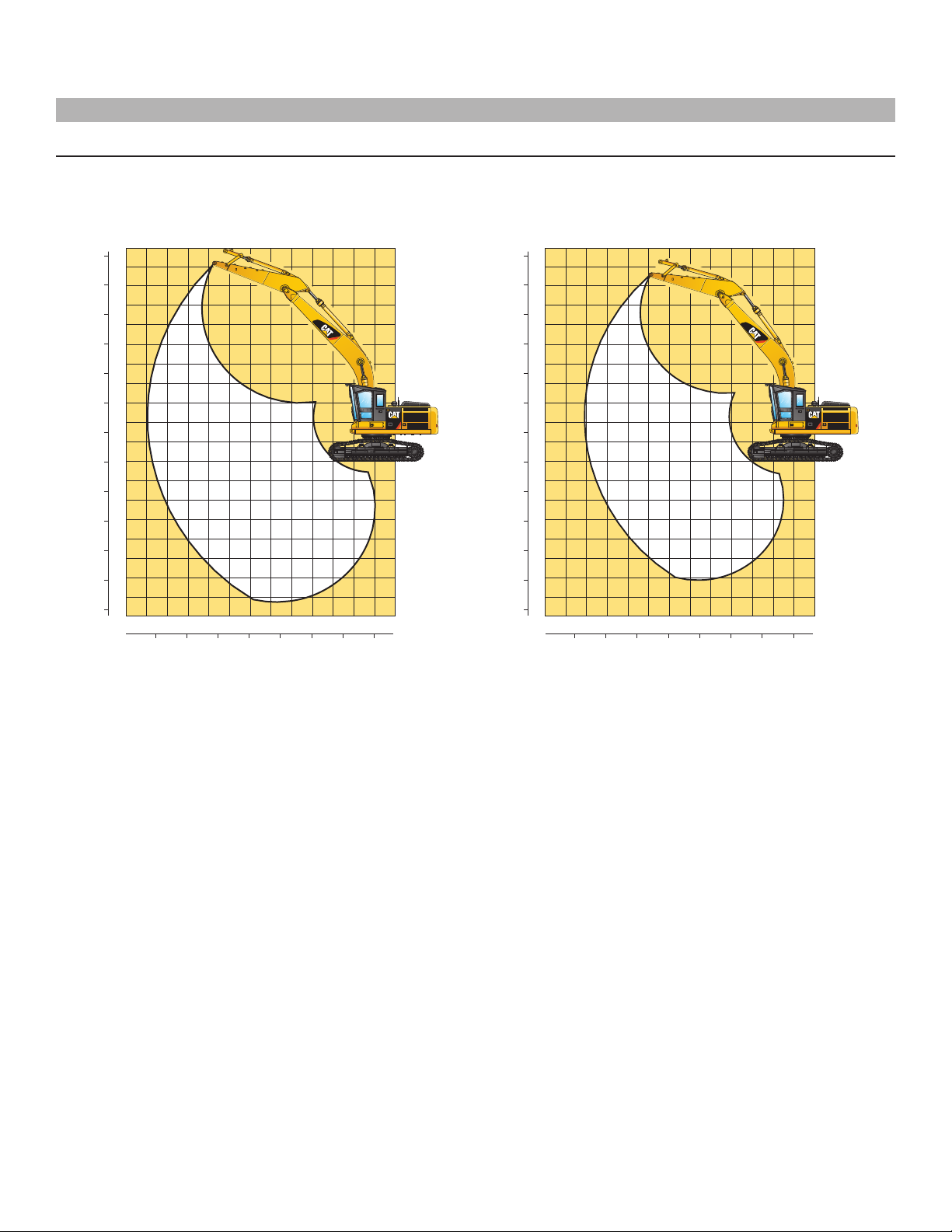
Working Ranges
Reach Boom and Mass Boom Ranges
568 FM GF 3.9M Reach Boom 568 FM GF 3.5M Mass Boom
Feet Meters
11
35
10
30
9
8
25
7
20
6
5
15
4
10
3
2
5
1
0
0
1
5
2
3
10
4
15
5
6
20
7
25
11 10 9 8 7 6 5 4 3 2 1 0 -1
35 30 25 20 15 10 5 0 Feet 35 30 25 20 15 10 5 0 Feet
Meters
Feet Meters
11
35
10
30
9
8
25
7
20
6
5
15
4
10
3
2
5
1
0
0
1
5
2
3
10
4
15
5
6
20
7
25
11 10 9 8 7 6 5 4 3 2 1 0 -1
Meters
19
Page 20
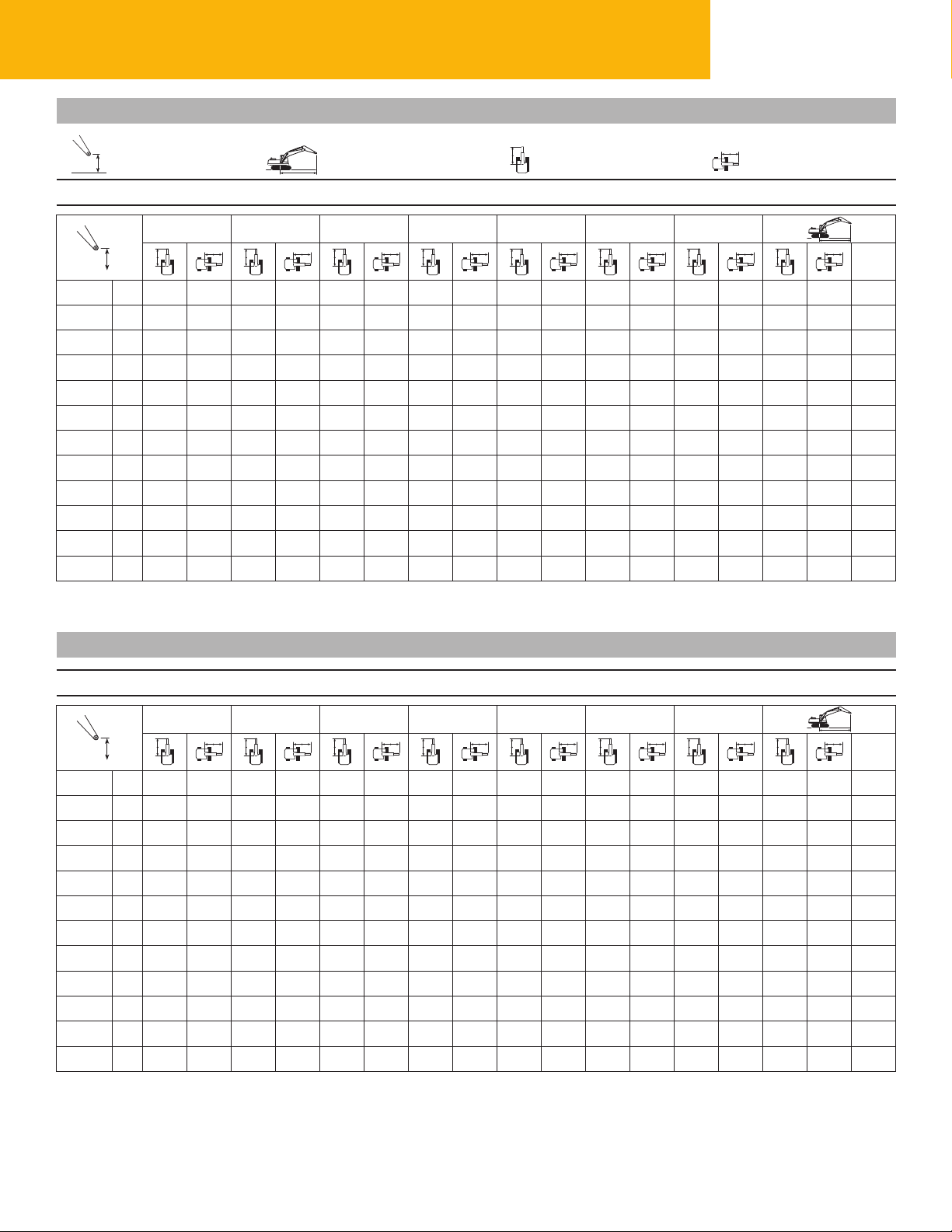
568 Forest Machine Speci cations
568 FM LL Boom U/U Lift Capacities
Load Point Height Load at Maximum Reach Load Radius Over Front Load Radius Over Side
Configuration – 13.1 m (43 ft) Boom/Stick/Heel Linkage Heavy Counterweight Shoes – 700 mm (28 in) Double Grouser
3.0 m/10.0 ft 4.5 m/15.0 ft 6.0 m/20.0 ft 7.5 m/25.0 ft 9.0 m/30.0 ft 10.5 m/35.0 ft 12.0 m/40.0 ft
12.0 m kg
40.0 ft lb
10.5 m kg
35.0 ft lb
9.0 m kg
30.0 ft lb
7.5 m kg
25.0 ft lb
6.0 m kg
20.0 ft lb
4.5 m kg
15.0 ft lb
3.0 m kg
10.0 ft lb
1.5 m kg
5.0 ft lb
Ground
Line
–1.5 m kg
–5.0 ft lb
–3.0 m kg
–10.0 ft lb
–4.5 m kg
–15.0 ft lb
*11 580 *11 580 *15 175 14 490 *13 495 10 151 11 286 7581 8789 5879 7049 4661 5545 4054 12.93
*23,563 *23,563 *32,383 *23,563 *29,291 21,864 24,277 16,314 18,897 12,633 15,133 9986 12,248 8956 42.38
kg
lb
*5304 *5304 *10 334 *10 334 *14 453 11 713 *11 483 8512 *8968 6600 *6476 5342 *4385 *4385 11.61
*12,077 *12,077 *23,801 *23,801 *31,178 *23,801 *24,673 18,350 *19,108 14,232 *13,401 11,532 *9713 *9713 37.97
*8563 *8563 *18 394 12 223 13 767 8868 10 452 6817 8310 5434 6827 4451 *4920 4030 12.92
*20,438 *20,438 *39,862 *20,438 29,623 19,110 22,503 14,685 17,896 11,699 14,709 9587 *10,846 8884 42.39
*8599 *8599 *17 052 11 853 *13 403 8621 10 284 6662 8222 5351 *5514 4444 *3961 *3961 12.55
*19,994 *19,994 *36,924 *19,994 *28,960 18,578 22,147 14,358 17,716 11,532 *10,729 9611 *8742 *8742 41.14
*12 905 *12 905 *12 789 10 535 *11 242 7808 8924 6005 7091 4700 *5768 4270 12.58
*27,715 *27,715 *27,808 22,676 *24,453 16,788 19,170 12,887 *14,650 10,029 *12,737 9455 41.17
*17 581 13 661 *14 182 9694 10 993 7312 8622 5724 6971 4587 5413 3949 13.10
*38,085 29,428 *30,751 20,888 23,656 15,744 18,549 12,308 14,985 9847 11,940 8711 42.99
*18 498 12 847 14 183 9240 10 700 7044 8453 5566 6888 4509 *3961 *3961 12.55
*40,079 27,688 30,518 19,914 23,032 15,170 18,193 11,976 14,823 9694 11,915 8687 42.98
*10 576 *10 576 *8447 *8447 *6187 *6187 *5523 *5523 9.65
*22,546 *22,546 *17,852 *17,852 *12,865 *12,865 *12,421 *12,421 31.20
*Limited by hydraulic capacity rather than tipping load. The above loads are in compliance with hydraulic excavator lift capacity standard ISO 10567. They do not exceed
87% of hydraulic lifting capacity or 75% of tipping capacity. Weight of work tool attachment and/or load lifting accessories must be deducted from the above lifting capacities.
*11 012 10 569
*24,277 *22,171
*12 224 10 859 *10 253 7898 *6941 6144 10.19
*26,949 23,266 *20,555 16,841 *15,502 13,859 32.98
*12 060 10 910 *10 948 8004 *8837 6031 *6338 5204 11.25
*26,588 23,429 *23,939 17,155 *16,737 12,835 *14,073 11,629 36.61
*12 272 10 795 *11 001 7958 8995 6071 *5976 4630 12.02
*27,055 23,215 *23,983 17,091 19,292 13,001 *13,224 10,289 39.29
m
ft
568 FM LL Boom O/U Lift Capacities
Configuration – 13.6 m (45 ft) Boom/Stick/Heel Linkage Heavy Counterweight Shoes – 700 mm (28 in) Double Grouser
3.0 m/10.0 ft 4.5 m/15.0 ft 6.0 m/20.0 ft 7.5 m/25.0 ft 9.0 m/30.0 ft 10.5 m/35.0 ft 12.0 m/40.0 ft
12.0 m kg *9805
40.0 ft lb *21,617
10.5 m kg *12 572 *10 761 *10 382 *6121 5501 10.94
35.0 ft lb *27,716 *21,530 *21,530 *13,654 12,377 35.48
9.0 m kg *14 323 *14 323 *12 627 10 377 *9784 7572 *5631 4730 11.93
30.0 ft lb *30,492 *31,577 *26,922 22,290 *19,151 16,221 *12,498 10,559 38.88
7.5 m kg *14 432 *12 696 10 185 11 197 7488 *7195 5713 6671 4938 *5326 4242 12.67
25.0 ft lb *31,817 *27,664 21,911 24,056 16,085 *15,862 12,595 *12,317 10,662 *11,785 9424 41.40
6.0 m kg *15 428 14 191 *13 067 9853 10 987 7295 8508 5608 6652 4730 *5144 3928 13.19
20.0 ft lb *33,483 31,286 *28,397 21,218 23,628 15,692 18,282 12,037 14,259 10,120 *11,361 8697 43.20
4.5 m kg *23 669 *23 669 *21 458 *21 458 *16 587 13 434 *13 589 9424 10 709 7041 8355 5465 6566 4651 *5056 3735 13.53
15.0 ft lb *47,672 *47,672 *46,355 *46,355 *35,932 *46,355 *29,479 20,306 23,044 15,155 17,971 11,748 14,097 9971 *11,153 8251 44.35
3.0 m kg *23 932 19 818 *17 659 12 606 13 890 8962 10 409 6765 8183 5305 6450 4545 5222 3638 13.69
10.0 ft lb *51,735 42,692 *38,240 42,692 29,887 19,314 22,405 14,569 17,611 11,412 13,864 9984 11,519 8025 44.92
1.5 m kg *17 108 *17 108 *18 037 11 892 13 426 8547 10 135 6514 8024 5157 6333 6333 5208 3624 13.69
5.0 ft lb *41,726 39,711 *39,081 39,711 28,889 18,418 21,817 14,029 17,278 11,102 13,622 9684 11,482 7989 44.92
Ground
*Limited by hydraulic capacity rather than tipping load. The above loads are in compliance with hydraulic excavator lift capacity standard ISO 10567. They do not exceed
87% of hydraulic lifting capacity or 75% of tipping capacity. Weight of work tool attachment and/or load lifting accessories must be deducted from the above lifting capacities.
Always refer to the appropriate Operation and Maintenance Manual for specific product information.
kg *3531 *3531 *11 487 *11 487 *17 266 11 420 13 085 8242 9926 6322 7910 5051 6235 6235 *4649 3694 13.52
Line
lb *8127 *8127 *26,760 *26,760 *37,427 *26,760 28,151 17,756 21,371 13,619 17,043 10,883 13,427 9725 *10,250 8145 44.36
–1.5 m kg *5648 *5648 *11 643 *11 643 *15 213 11 194 *11 995 8072 *9371 6216 *6807 5013 6185 4300 *3723 *3723 13.18
–5.0 ft lb *12,794 *12,794 *26,727 *26,727 *32,939 *26,727 *25,876 17,390 *20,075 13,397 *14,192 10,820 13,340 9273 *8173 *8173 43.21
–3.0 m kg *13 271 *13 271 *11 897 11 168 *9486 8039 *7085 6214 *4249 *4249 *3915 *3915 12.37
–10.0 ft lb *30,328 *30,328 *25,610 *30,328 *20,279 17,327 *14,877 13,408 *8675 *8675 *8665 8665 40.47
–4.5 m kg *4692 *4635 10.73
–15.0 ft lb *10,344 10,344 35.21
m
ft
20
Page 21
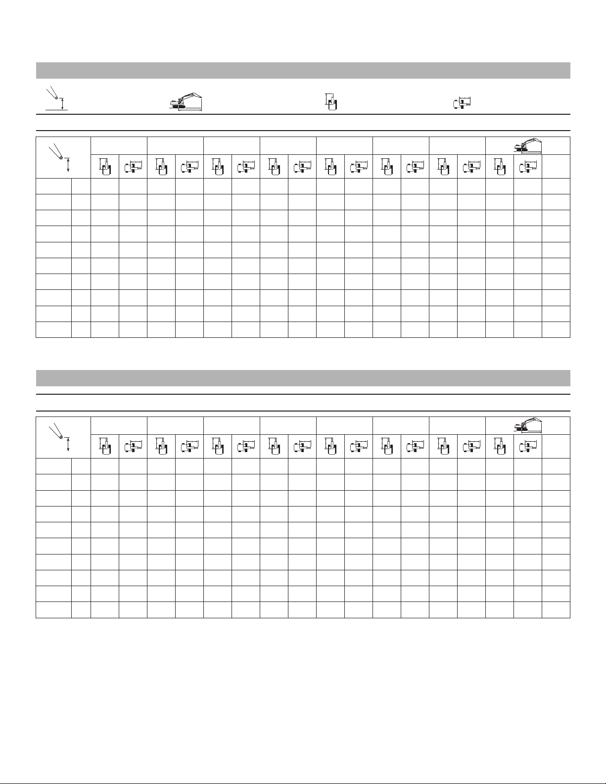
568 FM LL Boom BNT Lift Capacities
Load Point Height Load at Maximum Reach Load Radius Over Front Load Radius Over Side
Configuration – 13.1 m (40') Boom/Stick Heavy Counterweight Shoes – 700 mm (28 in) Double Grouser
3.0 m/10.0 ft 4.5 m/15.0 ft 6.0 m/20.0 ft 7.5 m/25.0 ft 9.0 m/30.0 ft 10.5 m/35.0 ft 12.0 m/40.0 ft
10.5 m kg *14 650 *14 650 *13 100 11 750 *9050 8500 *8950 8500 9.01
35.0 ft lb *32,250 *32,250 *28,800 25,100 19,952 18,739 *20,000 19,200 29.04
9.0 m kg *12 900 11 850 11 500 8800 *8050 7050 10.19
30.0 ft lb *31,650 *31,650 *28,150 25,400 24,700 18,850 *17,900 15,700 33.10
7.5 m kg *14 100 *14 100 *13 100 11 750 11 500 8800 8950 6850 *7550 6200 11.03
25.0 ft lb *31,200 *31,200 *28,450 25,250 24,750 18,900 19,150 14,600 *16,650 13,750 36.01
6.0 m kg *14 650 *14 650 *13 550 11 500 11 400 8700 8950 6800 *7250 5700 11.63
20.0 ft lb *32,400 *32,400 *29,400 24,750 24,500 18,700 19,200 14,600 *15,950 12,600 38.04
4.5 m kg *17 150 15 600 *14 150 11 150 11 200 8500 8850 6700 *7150 5400 *7100 5400 12.00
15.0 ft lb *37,150 33,600 *30,650 24,000 24,050 18,250 19,000 14,450 15,763 11,905 *15,650 11,900 39.33
3.0 m kg *18 300 14 850 14 350 12 750 10 950 8250 8700 6600 7150 5400 7000 5250 12.18
10.0 ft lb *39,550 31,950 30,850 23,150 23,550 17,800 18,750 14,150 15,763 11,905 15,350 11,600 39.95
1.5 m kg *18 650 14 150 13 900 10 350 10 700 8050 8600 6450 7100 5350 *6450 5250 12.17
5.0 ft lb *40,450 30,450 29,950 22,300 23,050 17,300 18,450 13,900 15,653 11,795 *14,250 11,550 39.93
Ground
*Limited by hydraulic capacity rather than tipping load. The above loads are in compliance with hydraulic excavator lift capacity standard ISO 10567. They do not exceed
87% of hydraulic lifting capacity or 75% of tipping capacity. Weight of work tool attachment and/or load lifting accessories must be deducted from the above lifting capacities.
kg *17 950 13 650 13 600 10 050 10 500 7850 8500 6400 *5450 5400 11.97
Line
lb *38,850 29,400 29,300 22,650 22,650 16,900 18,250 13,750 *12,000 11,800 39.28
–1.5 m kg *7200 *7200 *15 900 13 400 *12 700 9900 10 050 7750 *7500 6350 *4750 *4750 11.49
–5.0 ft lb *16,800 *16,800 *34,500 28,900 *27,400 21,300 *21,550 16,700 *15,700 13,650 *10,500 *10,500 37.66
–3.0 m kg *10 200 *10 200 *12 700 *12 700 *10 250 9850 *7850 7750 *5450 *5450 10.23
–10.0 ft lb *23,550 *23,550 *27,350 *27,350 *21,950 21,200 *16,500 *16,500 *12,050 *12,050 33.38
m
ft
568 FM Mass Linkage 3.5M Stick (Heavy Lift On)
Configuration – 3.5M Mass Boom and Mass Stick Heavy Counterweight Shoes – 700 mm (28 in) Double Grouser
1.5 m/5.0 ft 3.0 m/10.0 ft 4.5 m/15.0 ft 6.0 m/20.0 ft 7.5 m/25.0 ft 9.0 m/30.0 ft 10.5 m/35.0 ft
9.0 m kg *5554 *5978 *5578 *5579 7.33
30.0 ft lb *12,218 *12,218 *12,272 *12,272 24.05
7.5 m kg *7917 *7917 *5187 *5187 8.52
25.0 ft lb *17,418 *17,418 *11,412 *11,412 27.96
6.0 m kg *8209 *8209 *6920 *6920 *4614 *5036 *5036 9.32
20.0 ft lb *18,060 *18,060 *15,224 *15,224 *11,079 *11,079 30.57
4.5 m kg *9797 *9797 *8921 *8921 *8413 *8413 *6003 *5044 *5044 9.81
15.0 ft lb *21,553 *19,627 *19,627 *18,509 *18,509 *11,085 *11,085 32.19
3.0 m kg *14 763 *14 763 *11 524 *11 524 *9854 *9854 *8877 8259 *7053 *5173 *5173 10.05
10.0 ft lb *48,617 *48,627 *32,479 *32,479 *25,353 *32,479 *21,679 *21,679 *19,530 18,169 *11,381 *11,381 32.97
1.5 m kg *10 839 *10 839 *17 827 *17 827 *13 172 *13 172 *10 781 10 345 *9359 8088 *7597 *5451 *5451 10.05
5.0 ft lb *23,845 *23,845 *39,218 *39,218 *28,979 *39,218 *23,718 22,760 *20,589 17,793 *11,993 *11,993 32.97
Ground
*Limited by hydraulic capacity rather than tipping load. The above loads are in compliance with hydraulic excavator lift capacity standard ISO 10567. They do not exceed
87% of hydraulic lifting capacity or 75% of tipping capacity. Weight of work tool attachment and/or load lifting accessories must be deducted from the above lifting capacities.
Always refer to the appropriate Operation and Maintenance Manual for specific product information.
kg *12 346 *12 346 *19 537 *19 537 *14 326 13 605 *11 471 10 090 *9677 7949 *7243 *5920 *5920 9.81
Line
lb *16,626 *16,626 *27,162 *27,162 *42,982 *42,982 *31,518 *42,982 *25,236 22,198 *21,289 17,489 *13,024 *13,024 32.20
–1.5 m kg *11 073 *11 073 *16 643 *16 643 *19 868 *19 868 *14 758 13 365 *11 714 9937 *9586 7884 *6693 *6693 9.32
–5.0 ft lb *24,361 *24,361 *36,614 *36,614 *43,710 *43,710 *32,468 *43,710 *25,771 21,862 *21,088 17,345 *14,725 *14,725 30.58
–3.0 m kg *16 129 *16 129 *22 759 *22 759 *18 978 *18 978 *14 316 13 312 *11 243 9915 *8056 *8056 8.53
–10.0 ft lb *35,484 *35,484 *50,069 *50,069 *41,751 *41,751 *31,496 *41,751 *24,734 21,814 *17,724 *17,724 27.99
–4.5 m kg *22 355 *22 355 *23 115 *23 115 *16 675 *16 675 *12 627 *12 627 *9427 *9501 *9412 *9412 7.34
–15.0 ft lb *20,707 *20,707 24.08
m
ft
21
Page 22

568 Forest Machine Speci cations
568 FM Reach Linkage 3.9M Stick (Heavy Lift On)
Load Point Height Load at Maximum Reach Load Radius Over Front Load Radius Over Side
Configuration – 3.9M Reach Boom and Reach Stick Heavy Counterweight Shoes – 700 mm (28 in) Double Grouser
1.5 m/5.0 ft 3.0 m/10.0 ft 4.5 m/15.0 ft 6.0 m/20.0 ft 7.5 m/25.0 ft 9.0 m/30.0 ft 10.5 m/35.0 ft
9.0 m kg *4994 *4994 8.59
30.0 ft lb *10,986 *10,986 28.18
7.5 m kg *6714 *6714 *4714 *4714 9.63
25.0 ft lb *14,770 *14,770 *10,376 *10,376 31.60
6.0 m kg *7125 *7125 *4614 *4620 *4616 *4616 10.34
20.0 ft lb *15,675 *15,675 *10,152 *10,152 *10,115 *10,115 33.93
4.5 m kg *7984 *7984 *7567 *7567 *6003 *6003 *4631 *4631 10.79
15.0 ft lb *17,564 *17,564 *16,648 *16,648 *13,207 *13,207 *10,190 *10,190 35.38
3.0 m kg *21 877 *21 858 *13 250 *13 250 *10 482 *10 482 *9031 *9031 *8166 *8166 *7053 6692 *4748 *4748 11.00
10.0 ft lb *48,130 *48,021 *29,150 *29,150 *23,060 *29,150 *19,868 *19,868 *17,966 *17,966 *15,517 14,721 *10,445 *10,445 36.10
1.5 m kg *10 605 *10 605 *16 635 *16 635 *12 311 *12 311 *10 098 *10 098 *8793 8123 *7597 6579 *4975 *4975 11.00
5.0 ft lb *23,330 *23,330 *36,597 *36,597 *27,083 *36,597 *22,215 *22,215 *19,345 17,870 *16,713 14,474 *10,945 *10,945 36.10
Ground
*Limited by hydraulic capacity rather than tipping load. The above loads are in compliance with hydraulic excavator lift capacity standard ISO 10567. They do not exceed
87% of hydraulic lifting capacity or 75% of tipping capacity. Weight of work tool attachment and/or load lifting accessories must be deducted from the above lifting capacities.
Always refer to the appropriate Operation and Maintenance Manual for specific product information.
kg *5732 *5732 *10 578 *10 578 *18 820 *18 820 *13 719 13 625 *10 978 10 094 *9313 7939 *7243 6484 *5345 *5345 10.79
Line
lb *12,610 *12,610 *23,272 *23,272 *41,405 *41,405 *30,181 *41,405 *24,151 22,208 *20,488 17,465 *15,934 14,266 *11,758 *11,758 35.39
–1.5 m kg *8833 *8833 *13 485 *13 485 *19 684 *19 684 *14 489 13 305 *11 501 9884 *9579 7813 *5927 *5927 10.34
–5.0 ft lb *19,432 *19,432 *29,666 *29,666 *43,304 *43,304 *31,875 *43,304 *25,302 21,744 *21,074 17,189 *12,845 *13,039 *13,039 33.93
–3.0 m kg *12 712 *12 712 *17 812 *17 812 *19 429 *19 429 *14 531 13 171 *11 513 9789 *9380 7775 *6882 *6882 9.64
–10.0 ft lb *27,966 *27,966 *39,186 *39,186 *42,743 *42,743 *31,968 *42,743 *25,329 21,536 *20,635 17,105 *15,141 *15,141 31.62
–4.5 m kg *17 331 *17 331 *23 869 *23 869 *18 064 *18 064 *13 696 13 208 *10 744 9829 *8639 8316 8.60
–15.0 ft lb *19,006 18,296 28.23
–6.0 m kg *21 028 *21 028 *15 189 *15 189 *11 470 *11 470 *8819 *8819 *8799 *8799 7.10
–20.0 ft lb *19,358 *19,358 23.30
m
ft
22
Page 23

Standard equipment may vary. Consult your Cat dealer for details.
568 Standard Equipment
POWER TRAIN
®
C9.3 ATAAC engine
Cat
Meets U.S. EPA Tier 4 Interim
emissionsstandards
Bio Diesel capable
2300 m (7,500 ft) altitude capability
Electric priming fuel pump
2×4 micron main lters and 1×10 micron
primary lter in fuel line
24-volt electric starting
Air intake heater
Automatic engine speed control with one
touch low idle
Water separator in fuel line
Two speed auto-shift travel
Easy clean cooling system with full screens
Muf er
Flexxaire auto reversing fan
High ambient cooling capacity,
48° C (118° F)
Side by side cores
Starting aid cold weather starting package
with two additional batteries, HD starter,
ether and block heater
HYDRAULIC SYSTEM
Regeneration circuit for boom and stick
Reverse swing dampening valve
Automatic swing parking brake
High performance hydraulic return lter
Capability of installing HP stackable valve
and medium and QC valve
Standard auxiliary pump adjustable
to108 L/min (28.5 gal/min)
Capability of installing boom lowering control
device and stick lowering check valve
Capability of installing Cat Bio hydraulic oil
UNDERCARRIAGE
Straddle mounted carrier rollers
Heavy duty track motor guard
Heavy duty track rollers (10 per side)
Heavy duty recoil mechanism
345 HD, GLT4 Track
Idler track guiding guards
Full length track shoe support
GFT80 high drawbar FD
Towing eye on base frame
ELECTRICAL
80 ampere alternator
4 front working lights cab top mounted
1 left side working light
2 right front working lights
2 riser mounted lights
1 rear working light
Horn
Pre-start monitoring system (engine oil,
coolant hydraulic oil)
OPERATOR ENVIRONMENT
Purpose built forestry cab with scratch
resistant polycarbonate windows,
ISO8084 and SAE 1084 certi ed OPS,
ISO 8083 and SAE J231 certi ed FOPS,
and SAE J1356 certi ed FOGS,
OR-OSHA code 437-0775 TOPS and
WCB G602/G603/G604/G608
ROPS: ISO 3471:1997 Table 1, Section 1
Seat KAP 527P, air suspension, heated seat,
retractable seatbelt andheadrest
Integrated seat, console and joystick
typecontrols
Language display monitor with gauges,
Warning information, lter/ uid change
information, machine condition, error
code and tool mode setting information,
start up level check for hydraulic oil and
enginecoolant
Full time clock on monitor (2 weeks)
Seat mounted joystick with extra functions
for grapple
Fixed polycarbonate skylight with
retractable sun shade, meetingSAEJ1084
Interior lighting
Lower and upper windshield wipers
andwasher
Positive ltered ventilation, pressurized cab
Forced air fan
Behind seat storage tray with tie down points
2 CB radio mounts
1 re extinguisher mount
1 attachment computer control mount
Secondary roof exit openable from inside
2 coat hooks
Ashtray with lighter
Literature holder
Cup holder
Neutral lever (lockout) for all controls
Travel control pedals with removable
Washable oor mat
Radio/CD player (12V)
1 converter/2 sockets – 12V-10A power supply
with bi-level air conditioner, heater and
defroster with manual control
and outside
handlevers
FLUIDS
Antifreeze
Includes 50% concentration with protection
of –34° C (–30° F)
OTHER STANDARD EQUIPMENT
Heavy duty upper frame with catwalks
Heavy duty bottom guard
Heavy duty side doors
Core hydraulic lines and controls with
standard main valves onupperstructures
Door and cover locks with Cat one key
security system
Automatic swing parking brake
Fully pressurized hydraulic system
Fine swing control travel alarm
Counterweight with lifting eye
Right front corner guard
Right front corner fuel tank and standard
fuel tank
321SR Product Link
23
Page 24

568 Mandatory Attachments
Mandatory Attachments may vary. Consult your Cat dealer for details.
BOOMS, STICKS AND LINKAGES
Front Linkage
(must select one of the following)
Omission, front linkage
Linkage, Reach – GF, 3.9 m (12.8 ft)
Linkage, Mass – GF, 3.5 m (11.5 ft)
Linkage, LL, top cylinder
Linkage, LL, bottom cylinder
Butt-N-Top combo
UNDERCARRIAGE
(must select one of the following)
Track, 700 mm (28 in) DG with trap holes
Track, 850 mm (34 in) HD TG with trap holes
HYDRAULICS
Main Control Valve
(must select one of thefollowing)
Valve, no attachment section
Valve, with attachment section
Valve, log loader
OPERATOR ENVIRONMENT
(must select one ofthe following)
Cab, GF, 457 mm (18 in) riser
Cab, LL, 1219 mm (48 in) riser
Cab, AEM platform
SEAT
(must select one of the following)
Seat, air suspension with heat
Seat, air suspension with heat and cooling
OTHER ATTACHMENTS
Counterweights
(must select one of thefollowing)
Counterweight, standard
Counterweight, heavy
24
Page 25

Optional equipment may vary. Consult your Cat dealer for details.
568 Optional Equipment
BOOMS, STICKS AND LINKAGES
Front Linkage
Cylinders, boom + pin (not installed)
Linkage, bucket, DB family
Grapples
Grapple, GLL52B log loading
Grapple, GLL55B log loading
Grapple, GLL60B log loading
Heels
Heel, GLL, with bottom mounted cylinder
Heel, GLL, with top mounted cylinder
Heel, GLL with offset for bottom
mounted cylinder
HYDRAULICS
Thumb control
LINE GROUPS
Boom Lines
Lines – HP, Reach boom, GF,
3.9 m (12.8 ft)
Lines – MP, Reach boom, GF,
3.9 m (12.8 ft)
Lines – HP, Mass boom, GF,
3.5 m (11.5 ft)
Lines – MP, Mass boom, GF,
3.5 m (11.5 ft)
Stick Lines
Lines – HP, GF, 3.5 m (11.5 ft) stick
Lines – MP, GF, 3.5 m (11.5 ft) stick
Lines – HP, GF, 3.9 m (12.8 ft) stick
Lines – MP, GF, 3.9 m (12.8 ft) stick
OTHER ATTACHMENTS
Straight travel pedal
Auxiliary drive
International – ISO lms
FLUIDS
Antifreeze
Antifreeze, –50° C (–58° F)
FIELD INSTALLED ATTACHMENTS
Kit, AEM cab installation
Kit, Butt-N-Top installation
PACKING
Domestic
Pack, domestic truck, drive out
Pack, domestic truck HEX
Pack, domestic truck – boom and stick
removed
Pack, domestic rail
Miscellaneous
Pack, miscellaneous HEX shipments
Order Change Charges
Order change charges (track)
25
Page 26

Notes
26
Page 27

27
Page 28

568 Forest Machine
For more complete information on Cat products, dealer services, and industry solutions,
visit us on the web at www.cat.com
© 2011 Caterpillar Inc.
All rights reserved
Materials and specications are subject to change without notice. Featured machines
in photos may include additional equipment. See your Cat dealer for available options.
CAT, CATERPILLAR, SAFETY.CAT.COM, their respective logos, “Caterpillar Yellow”
and the “Power Edge” trade dress, as well as corporate and product identity used herein,
are trademarks of Caterpillar and may not be used without permission.
20
AEHQ6269 (05-2011)
 Loading...