

Page 1

Operation and
CAT00277CCNC01411
Maintenance
Manual
SEBU7494-06
December 2005
247, 257, 267, 277 and 287 Multi
Terrain Loaders
CNC1-Up
CML1-Up (Machine)
CMM1-Up (Machine)
CMP1-Up
CNY1-Up (Machine)
(Machine)
(Machine)
Page 2

i01658146
Important Safety Information
Most accidents t
basic safety rules or precautions. An accident can often be avoided by recognizing potentially hazardous
situations before an accident occurs. A person must be alert to potential hazards. This person should also
have the necess
Improper operation, lubrication, maintenance or repair of this product can be dangerous and
could result in injury or death.
Do not operate o
read and understood the operation, lubrication, maintenance and repair information.
Safety precautions and warnings are provided in this manual and on the product. If these hazard warnings
are not heeded
The hazards are identified by the “Safety Alert Symbol” and followed by a “Signal Word” such as
“DANGER”, “WARNING” or “CAUTION”. The Safety Alert “WARNING” label is shown below.
The meaning of this safety alert symbol is as follows:
Attention! Be
The message that appears under the warning explains the hazard and can be either written or pictorially
presented.
Operations th
this publication.
hat involve product operation, maintenance and repair are caused by failure to observe
ary training, skills and tools to perform these functions properly.
r perform any lubrication, maintenance or repair on this product, until you have
, bodily injury or death could occur to you or to other persons.
come Alert! Your Safety is Involved.
at may cause product damage are identified by “NOTICE” labels on the product and in
Caterpillar cannot anticipate every possible circumstance that might involve a potential hazard.
The warnings
procedure, work method or operating technique that is not specifically recommended by Caterpillar
is used, you must satisfy yourself that it is safe for you and for others. You should also ensure that
the product w
repair procedures that you choose.
The information, specifications, and illustrations in this publication are on the basis of information that
was availabl
measurements, adjustments, illustrations, and other items can change at any time. These changes can
affect the service that is given to the product. Obtain the complete and most current information before you
start any jo
in this publication and on the product are, therefore, not all inclusive. If a tool,
ill not be damaged or be made unsafe by the operation, lubrication, maintenance or
e at the time that the publication was written. The specifications, torques, pressures,
b. Caterpillar dealers have the most current information available.
When replacement parts are required for this
product Caterpillar recommends using Caterpillar replac
specifications including, but not limited to, physical dimensions, type, strength and ma terial.
Failure to heed this warning can lead to premature failures, product damage, personal injury or
death.
ement parts or parts with equivalent
Page 3

SEBU7494-06 3
Table of Contents
Table of Contents
Foreword ................................................................. 4
Safety Section
Safety Messages .................................................... 6
General Hazard Information ................................. 22
Crushing Prevention and Cutting Prevention ........ 24
Burn Prevention .................................................... 24
Fire Prevention and Explosion Prevention ............ 25
Fire Extinguisher Location .................................... 27
Electrical Storm Injury Prevention ......................... 27
Before Starting Engine .......................................... 27
Engine Starting ..................................................... 27
Before Operation .................................................. 28
Engine Startin
Maintenance Se
Maintenance Access ............................................. 88
Lubricant Viscosities and Refill Capacities ........... 94
Maintenance S
Maintenance Interval Schedule ............................ 98
g (Alternate Methods) ..................... 86
ction
upport ............................................ 97
Reference Information Section
Reference Materials ............................................ 146
Index Section
Index ................................................................... 151
Operation .............................................................. 28
Work Tools ............................................................ 28
Parking .................................................................. 29
Equipment Lowering with Engine Stopped ........... 29
Sound Information and Vibration Information ....... 29
Guards (Operator Protection) . .............................. 30
Product Information Section
General Information .............................................. 32
Identification Information ....................................... 46
Operation Section
Before Operation .................................................. 48
Machine Operation ............................................... 54
Engine Starting ..................................................... 65
Operation .............................................................. 66
Parking .................................................................. 79
Transportation Information .................................... 82
Towing Information ................................................ 85
Page 4

4 SEBU7494-06
Foreword
Foreword
Literature Information
This manual sho
compartment in the literature holder or seat back
literature storage area.
This manual contains safety information, operation
instructions, transportation information, lubrication
information
Some photographs or illustrations in this publication
show details
from your machine. Guards and covers might have
been removed for illustrative purposes.
Continuing improvement and advancement of
product design might have caused changes to your
machine whic
Read, study and keep this manual with the machine.
Whenever a q
or this publication, please consult your Caterpillar
dealer for the latest available information.
Safety
uld be stored in the operator’s
and maintenance information.
or attachments that can be different
h are not included in this publication.
uestion arises regarding your machine,
Maintenance
The maintenanc
care. The Maintenance Interval Schedule (MIS) lists
the items to be maintained at a specific service
interval. Ite
under the "When Required" service interval. The
Maintenance Interval Schedule lists the page
number for th
accomplish the scheduled maintenance. Use the
Maintenance Interval Schedule as an index or "one
safe source"
Maintenance Intervals
Use the service hour meter to determine servicing
intervals. Calendar intervals shown (daily, weekly,
monthly, et
meter intervals if they provide more convenient
servicing schedules and approximate the indicated
service ho
should always be performed at the interval that
occurs first.
Under extremely severe, dusty or wet operating
conditions, more frequent lubrication than is
specified
be necessary.
e section is a guide to equipment
ms without specific intervals are listed
e step-by-step instructions required to
for all maintenance procedures.
c.) can be used instead of service hour
ur meter reading. Recommended service
in the maintenance intervals chart might
The safety section lists basic safety precautions. In
addition, this section identifies the text and locations
of warning
Read and understand the basic precautions listed
in the safe
lubrication, maintenance and repair on this machine.
signs and labels used on the machine.
ty section before operating or performing
Operation
The operat
operator and a refresher for the experienced
operator. This section includes a discussion of
gauges, s
controls, transportation and towing information.
Photogra
through correct procedures of checking, starting,
operating and stopping the machine.
Operating techniques outlined in this publication are
basic. Skill and techniques develop as the operator
gains kn
ion section is a reference for the new
witches, machine controls, attachment
phs and illustrations guide the operator
owledge of the machine and its capabilities.
Perform s
requirement. For example, at every 500 service
hours or 3 months, also service those items listed
under eve
10 service hours or daily.
ervice on items at multiples of the original
ry 250 service hours or monthly and every
California Proposition 65 Warning
Diesel e
are known to the State of California to cause cancer,
birth defects, and other reproductive harm.
Battery posts, terminals and related accessories
contain lead and lead compounds. Wa sh hands
after ha
Certifi
Proper maintenance and repair is essential to keep
the eng
As the heavy duty off-road diesel engine owner, you
are responsible for the performance of the required
mainte
and Maintenance Manual, and Service Manual.
ngine exhaust and some of its constituents
ndling.
ed Engine Maintenance
ine and machine systems operating correctly.
nance listed in the Owner Manual, Operation
Page 5

SEBU7494-06 5
Product ID: CAT00277CCNC01411
Foreword
It is prohibite
business of repairing, servicing, selling, leasing, or
trading engines or machines to remove, alter, or
render inoper
element of design installed on or in an engine or
machine that is in compliance with the regulations
(40 CFR Part 8
and engine such as the exhaust system, fuel system,
electrical system, intake air system and cooling
system may b
altered unless approved by Caterpillar.
d for any person engaged in the
ative any emission related device or
9). Certain elements of the machine
e emission related and should not be
Machine Capacity
Additional
machine design capacity which can adversely affect
performance characteristics. Included would be
stability a
steering, and rollover protective structures (ROPS).
Contact your Caterpillar dealer for further information.
attachments or modifications may exceed
nd system certifications such as brakes,
Caterpillar Product Identification
Number
Effective
Identification Number (PIN) has changed from 8 to 17
characters. In an effort to provide uniform equipment
identifi
equipment manufacturers are moving to comply
with the latest version of the product identification
numberin
defined by ISO 10261. The new PIN format will apply
to all Caterpillar machines and generator sets. The
PIN plat
character PIN. The new format will look like the
following:
First Quarter 2001 the Caterpillar Product
cation, Caterpillar and other construction
g standard. Non-road machine PINs are
esandframemarkingwilldisplaythe17
3. Check Charac
4. Machine Indicator Section (MIS) or Product
Sequence Numb
previously referred to as the Serial Number.
Machines and g
Quarter 2001 will maintain their 8 character PIN
format.
Components such as engines, transmissions, axles,
etc. and work tools will continue to use an 8 character
Serial Numbe
ter (character 9)
er (characters 10-17). These were
enerator sets produced before First
r(S/N).
Illustration 1
Where:
1. Caterpillar’s World Manufacturing Code
(characters 1-3)
2. Machine Descriptor (characters 4-8)
g00751314
Page 6

6 SEBU7494-06
Safety Section
Safety Messages
Safety Section
i02114035
Safety Me ssage s
SMCS Code: 7000; 7405
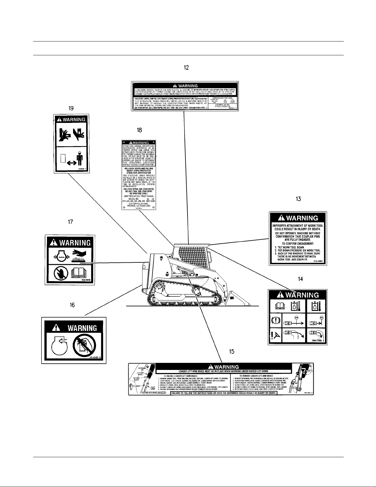
Illustration 2
Typical Example
g01005229
Page 7
SEBU7494-06 7
Safety Section
Safety Messages
Illustration 3
g01005251
Page 8

8 SEBU7494-06
Safety Section
Safety Messages
Typical Exampl
e
Page 9
SEBU7494-06 9
Safety Section
Safety Messages
Illustration 4
g01076981
Page 10
10 SEBU7494-06
Safety Section
Safety Messages
There are sever
machine. The exact location of the hazards and
the description of the hazards are reviewed in this
section. Plea
messages.
Make sure tha
Clean the safety messages or replace the safety
messages if you cannot read the words. Replace
the illustra
When you clean the safety messages, use a cloth,
water and soap. Do not use solvent, gasoline, or
other harsh
Solvents, gasoline, or harsh chemicals could loosen
the adhesive that secures the safety message. Loose
adhesive wi
Replace any safety message that is damaged, or
missing. If
that is replaced, install a safety message on the
replacement part. Any Caterpillar dealer can provide
new safety
al specific safety messages on this
se become familiarized with all safety
t all of the safety messages are legible.
tions if the illustrations are not legible.
chemicals to clean the safety messages.
ll allow the safety message to fall.
a safety message is attached to a part
messages.
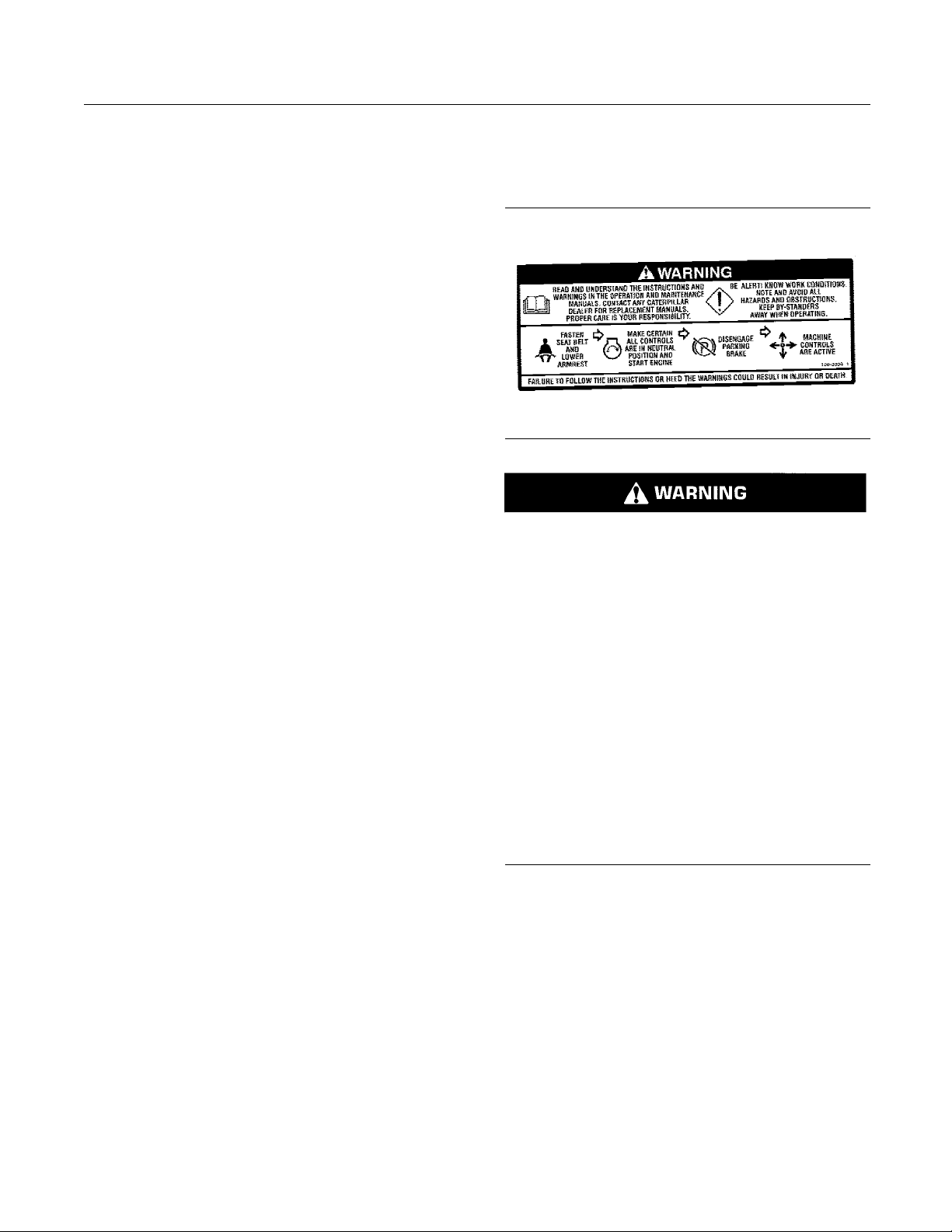
Do Not Operate (1)
This warning message is located inside the cab on
the left side.
g00943091
Read and understand the instructions and warnings in the ope ration and maintenance manuals.
Contact any Caterpillar dealer for replacement
manuals. Proper care is your responsibility.
Be alert! Know work conditions. Note and avoid all
hazards and obstructions. Keep by-standers away
when operating.
Fasten seat belt and lower armrest.
Make certain all controls are in neutral position
and start engine.
Disengage parking brake.
Machine controls are active.
Failure to follow the instructions or heed the warnings could result injury or death.
Page 11

SEBU7494-06 11
Safety Section
Safety Messages
Loader Crushing (2)
This message is located below the operator seat.
g00943101
Keep out of t
Loader lift arm brace must be in place when working unde r ra
his area
ised lift arm.
Carrying a Load (3)
This warning message is located below the operator
seat.
g00943103
Carry load low.
Do not exceed rated load.
Failure to follow the instructions or heed the warnings will r
esult in death or serious injury.
Load, unload, turn on level ground.
Travel up and down slope with heaviest end of
loader uphill.
Failure to follow the instructions or heed the warnings could result in injury or death.
Page 12

12 SEBU7494-06
Safety Section
Safety Messages
Never Permit Riders (4)
This warning message is located below the operator
seat.
g00943118
Never permit riders.
Never use work tool for a work platform.
Failure to follow the instructions or heed the warnings could result in injury or death.
Stay Inside Operator Station (5)
This warning message is located below the operator
seat.
g00943119
Keep your body inside operator station while operating loader.
Never work with your arms, feet or legs beyond
operator station.
Failure to follow the instructions or heed the warnings will result in death or serious injury.
Page 13

SEBU7494-06 13
Safety Section
Safety Messages
Mounting and Dismounting (6)
This warning message is located below the operator
seat.
g00943129
Mounting and Dismounting
Maintain 3-point contact (2 feet and 1 ha nd or 1
foot and 2 hands) with steps and handholds
Cab Support (7)
This warning message is located on the left side of
the machine near the cab support lever. This warning
message is also located inside the cab on the left
side.
g00943135
Do not go beneath cab unless cab is empty and
support lever is engaged.
When Leaving Loader:
1. Park machine on level ground
2. Lower work tool to ground
3. Stop engine and r emove ignition key
4. Raise arm rest and remove seat belt
Park Brake is applied automatically
Failure to follow the instructions or heed the warnings could result in injury or death
Failure to follow the instructions or heed the warnings could result in injury or death.
Page 14

14 SEBU7494-06
Safety Section
Safety Messages
Battery (8)
This warning message is located on the battery.
g00943142
DANGER/POISON
Shield eyes, Explosive gases. Can cause blindness or injury.
No sparks, flames or smoking.
Sulfuric Acid can cause blindness or severe
burns.
FLUSH EYES IMMEDIATELY WITH WATER. Get
medical help fast.
Keep out of reach of children. Contains sulfuric
acid. For medical emergency in USA or Canada
contact: 800-458-5924, other countries contact:
303-893-1322.
Batteries (9)
Thiswarningmessageislocatedontheinsideofthe
engine access door.
g00943143
Improper jumper cable connections can cause explosion resulting in personal injury. Batteries may
be located in separate compartments, always connect positive (+) cable to positive (+) terminal of
battery connected to starter solenoid and negative
(−) cable from external source to engine block or
frame.
Accumulator (10)
This warning message is located near the
accumulator.
g00943144
Accumulator may contain high pressure oil. Do
not service the accumulator or any hydraulic lines
ll of the pressure has been relieved. See the
until a
Service Manual for proper procedures. Failure to
heed this warning could result in injury or death.
Page 15
SEBU7494-06 15
Safety Section
Safety Messages
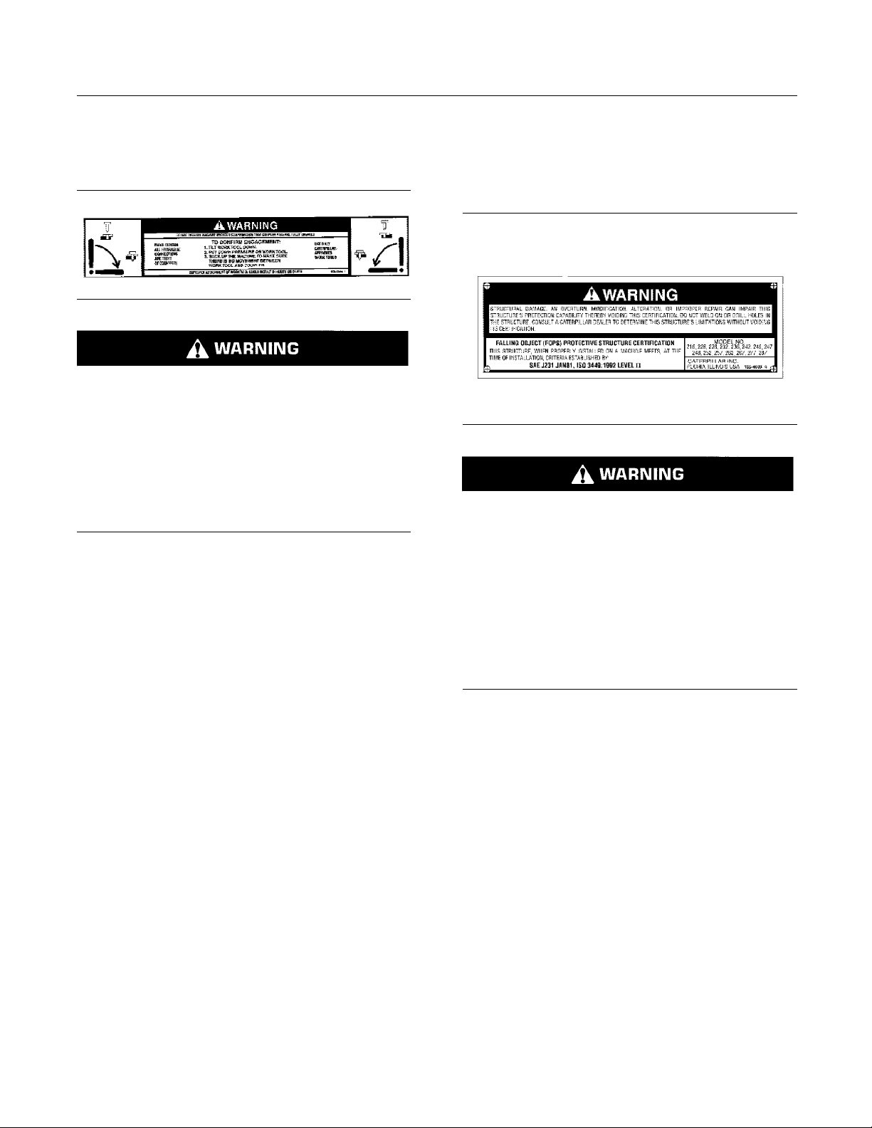
Work Tool Coupler (11)
This warning message is located on the coupler
assembly.
g00943146
Do not operate machine without confirmation that
coupler pins are fully engaged
Make certain all hydraulic connections are tight (if
equipped)
Use only Caterpillar approved work tools
Improper attachment of work tool could result in
injury or death
Tilt the work tool downward.
Put down pressure on the work tool.
Move the machine backward. Ensure that the work
tool has not separated from the coupler assembly.
Falling Object Protective Structure
(12)
This warning message is located on the right side of
the FOPS.
g00943148
Structural damage, an overturn, modification, alteration,orimproperrepaircanimpairthisstructure’s protection capability thereby voiding this
certification. Do not weld on or drill holes in the
structure. Consult a Caterpillar dealer to determine this structure’s limitations without voiding
its certification.
This structure, when properly ins talled on a machine meets, at the time of installation, criteria
established by: TOP GUARD: SAE J231, JAN 81,
“ISO 3449 Level II”.
Page 16

16 SEBU7494-06
Safety Section
Safety Messages
Work Tool Coupler (13)
This warning message is located inside the cab near
the hydraulic quick coupler control.
g00943149
Improper Attachment of the Work Tool could result
in injury or death.
Do not operate the machine without confirmation
that the coupler pins are f ully engaged. Follow the
operating procedures in the Operation and Maintenance Manual.
Machine Operation in Cold Weather
(14)
This warning message is located inside the cab on
the right side.
g00943150
The braking and steering system of this machine
react differently when the hydraulic oil is cold.
Operating the machine with cold hydraulic oil requires extra stopping and turning clearances. Failure to follow the instructions or heed the warnings
could result in injury or death.
Tilt the work tool downward.
Put down pressure on the work tool.
Move the machine backward. Ensure that the work
tool has not separated from the coupler assembly.
Refer to Operation and Maintenance Manual, “Engine
Starting” for information on machine preparation for
cold weather.
Page 17
SEBU7494-06 17
Safety Section
Safety Messages
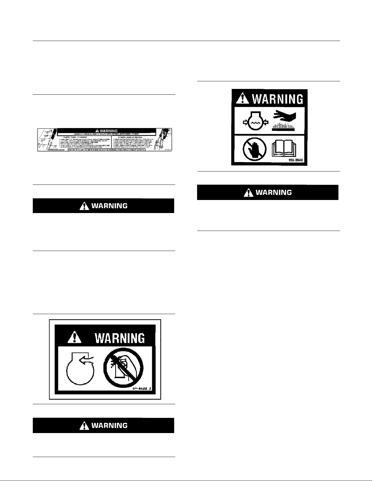
Brace for the Loader Lift Arms (15)
This warning message is located on the brace for the
loader lift arms. The illustration may vary depending
on the machine that is being serviced. However, the
location of the label will remain unchanged.
g00943151
Loader lift arm brace must be in place when working under raised lift arms.
Pressurized System (17)
This warning message is located below the radiator
cap.
g00943155
Pressurized system: Hot coolant can cause serious burn. To open cap, stop engine, wait until radiator is cool. Then loosen cap slowly to relieve
the pressure.
Failure to follow the instructions or heed the warnings could result in injury or death.
Refer to Operation and Maintenance Manual, “Loader
Lift Arm Brace Operation” for operating information.
Aerosol Starting Aid (16)
This warning message is located on top of the fuel
pump housing.
g00943154
Do not use aerosol types of starting aids such as
ether. Such use could result in an explosion and
person
al injury.
Page 18
18 SEBU7494-06
Safety Section
Safety Messages
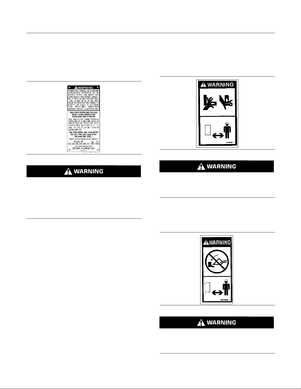
Rollover Protective Structure/
Falling Object Protective Structure
(18)
Thiswarningmessageislocatedinsidethecabon
the upper left side.
g00943157
Structural damage, an overturn, modification, alteration, or improper repair can impair this structure’s protection capability thereby voiding this
certification. Do not weld on or drill holes in the
structure. Consult a Caterpillar dealer to determine this structure’s limitations without voiding
its certification.
Crush Point (19)
The warning messages that are shown are used
on the 257 Multi Terrain Loaders and the 277 Multi
Terrain Loaders. The messages are located near the
back of the machine on each side.
g00943160
No clearance for person in this area during operation. Severe injury or death from crushing could
occur. Stay away from the work tool while it is in
operation.
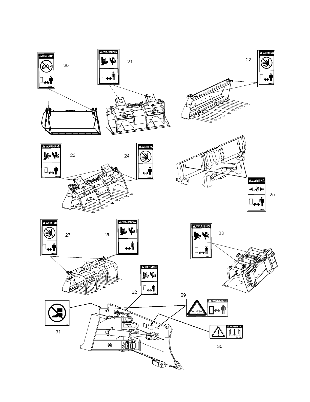
Multipurpose Bucket (20)
These warning messages are located on the front of
the multipurpose bucket.
g00943159
No clea
ation. Severe injury or death from crushing could
occur. Stay away from the work tool while it is in
operat
rance for person in this area during oper-
ion.
Page 19

SEBU7494-06 19
Safety Section
Safety Messages
Industrial Grapple Bucket (21)
These warning messages are located on top of the
guards for the grapple cylinders.
g00943160
No clearance for person in this area during operation. Severe injury or death from crushing could
occur. Stay away from the work tool while it is in
operation.
Industrial Grapple Fork (23)
These warning messages are located on the guards
for the grapple cylinders.
g00943172
No clearance for person in this area during operation. Severe injury or death from crushing could
occur. Stay away from the work tool while it is in
operation.
Utility Fork (22)
These warning messages are located on top of the
fork carriage.
g00943161
No clearance for person in this area during operation. Severe injury or death from impalement
could o
is in operation.
ccur. Stay away from the work tool while it
Industrial Grapple Fork (24)
These warning messages are located on top of the
fork carriage.
g00943175
No clearance for person in this area during operation. Severe injury or death from impalement
could o
is in operation.
ccur. Stay away from the work tool while it
Page 20
20 SEBU7494-06
Safety Section
Safety Messages
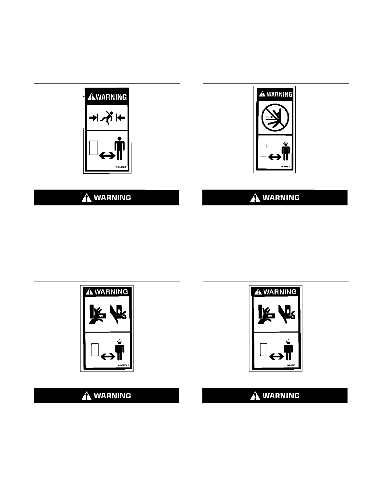
Angle Blade (25)
These warning messages are located on the back
side of the blade.
g00943177
No clearance for person in this area during operation. Severe injury or death from crushing could
occur. Stay away from the work tool while it is in
operation.
Utility Grapple Fork (27)
These warning messages are located on top of the
fork carriage.
g00943179
No clearance for person in this area during operation. Severe injury or death from impalement
could occur. Stay away from the work tool while it
is in operation.
Utility Grapple Fork (26)
These warning messages are located on top of the
grapple frame.
g00943178
No clearance for person in this area during operation. Severe injury or death from crushing could
occur.
operation.
Stay away from the work tool while it is in
Utility Grapple Bucket (28)
These warning messages are located on top of the
grapple frame.
g00943180
No clearance for person in this area during operation. Severe injury or death from crushing could
occur.
operation.
Stay away from the work tool while it is in
Page 21
SEBU7494-06 21
Safety Section
Safety Messages
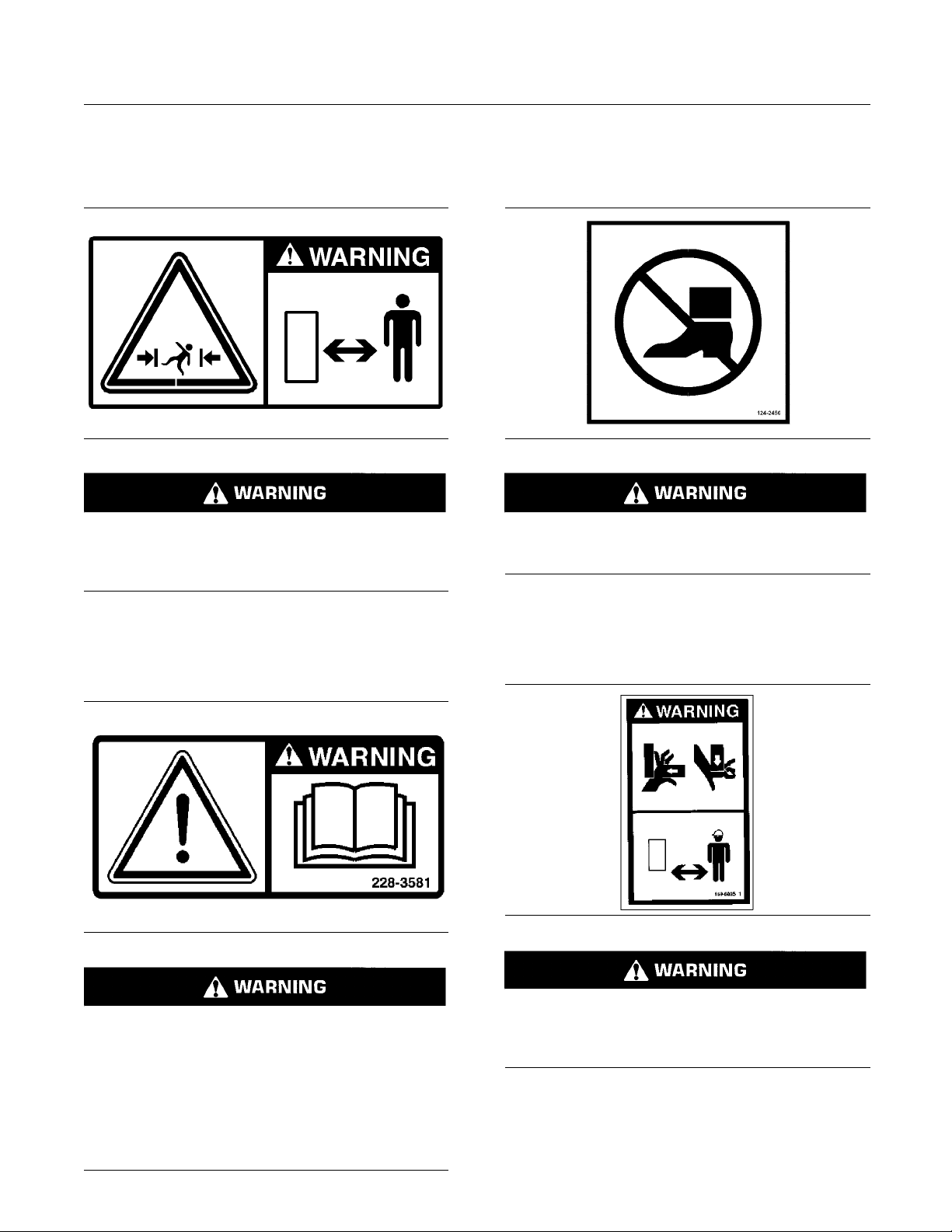
Dozer Blade (29)
These warning messages are located on the back
side of the blade.
g01039066
No clearance for person in this area during operation. Severe injury or death from crushing could
occur. Stay away from the work tool while it is in
operation.
Dozer Blade (31)
This warning message is located on top of the dozer
blade.
g00946617
Falling Hazard - Area may be oily and slippery.
Do not step on cylinders. Serious injury or death
could oc cur from a fall.
Dozer Blade (30)
This warning is located on right hand side on the
back of the blade.
g00934493
DO NOT OPERATE OR WORK ON THIS MACHINE
UNLESS YOU HAVE READ AND UNDERSTAND
THE INS
OPERATION AND MAINTENANCE MANUALS.
FAILURE TO FOLLOW THE INS TRUCTIONS OR
HEED TH
JURY OR DEATH. CONTACT ANY CATERPILLAR
DEALER FOR REPLACEMENT MANUALS. PROPER CAR
TRUCTIONS AND WARNINGS IN THE
E WARNINGS COULD RESULT IN IN-
E IS YOUR RESPONSIBILITY.
Dozer Blade (32)
This warning message is located on top of the dozer
blade.
g00943180
No clear
ation. Severe injury or death from crushing could
occur. Stay away from the work tool while it is in
operat
ance for person in this area during oper-
ion.
Page 22

22 SEBU7494-06
Safety Section
General Hazard Information
i02443908
General Hazard Information
SMCS Code: 7000
Illustration 5
Attach a “Do Not Operate” warning tag or a similar
warning tag to the start switch or to the controls
before you service the equipment or before you
repair the equipment. These warning tags (Special
Instruction, SEHS7332) are available from your
Caterpillar dealer.
Know the width of your equipment in order to maintain
proper clearance when you operate the equipment
near fences or near boundary obstacles.
Be aware of high voltage power lines and power
cables that are buried. If the machine comes in
contact with these hazards, serious injury or death
may occur from electrocution.
g00104545
Keep the equipm
ent free from foreign material.
Remove debris, oil, tools, and other items from the
deck, from walkways, and from steps.
Secure all loose items such as lunch boxes, tools,
and other items that are not a part of the equipment.
Know the appropriate work site hand signals and
the personnel that are authorized to give the hand
signals. Acc
ept hand signals from one person only.
Do not smoke when you service an air conditioner.
Also, do not s
moke if refrigerant gas may be present.
Inhaling the fumes that are released from a flame that
contacts air conditioner refrigerant can cause bodily
harm or death
. Inhaling gas from air conditioner
refrigerant through a lighted cigarette can cause
bodily harm or death.
Never put maintenance fluids into glass containers.
Drain all liquids into a suitable container.
Obey all local regulations for the disposal of liquids.
Use all clea
ning solutions with care. Report all
necessary repairs.
Do not allow
unauthorized personnel on the
equipment.
Unless you
are instructed otherwise, perform
maintenance with the equipment in the servicing
position. Refer to Operation and Maintenance Manual
for the pro
cedure for placing the equipment in the
servicing position.
Pressurized Air and Water
Illustration 6
Wear a ha
rd hat, protective glasses, and other
protective equipment, as required.
Do not we
ar loose clothing or jewelry that can snag
on controls or on other parts of the equipment.
Make sur
e that all protective guards and all covers
are secured in place on the equipment.
g00702020
Pressuri
zed air and/or water can cause debris
and/or hot water to be blown out. This could result in
personal injury.
When pressurized air and/or pressurized water is
used for cleaning, wear protective clothing, protective
shoes, an
d eye protection. Eye protection includes
goggles or a protective face shield.
The maxim
um air pressure for cleaning purposes
must be reduced to 205 kPa (30 psi) when the
nozzle is deadheaded and the nozzle is used with
an effec
tive chip deflector and personal protective
equipment. The maximum water pressure for
cleaning purposes must be below 275 kPa (40 psi).
Page 23
SEBU7494-06 23
Safety Section
General Hazard Information
Trapped Pressure
Pressure can be
Releasing trapped pressure can cause sudden
machine movement or attachment movement. Use
caution if you
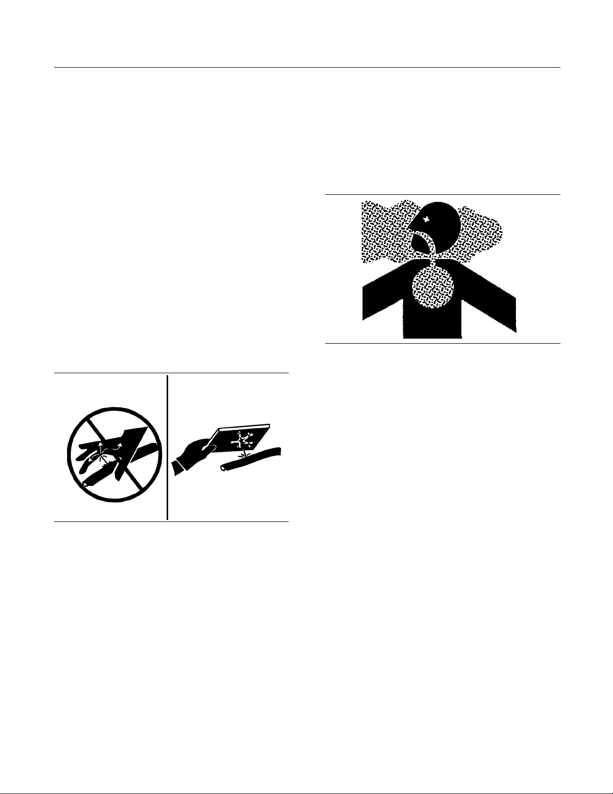
High pressure oil that is released can cause a hose to
whip. High pressure oil that is released can cause oil
to spray. Flu
and possible death.
trapped in a hydraulic system.
disconnect hydraulic lines or fittings.
id penetration can cause serious injury
Fluid Penetration
Pressure can
after the engine has been stopped. The pressure can
cause hydraulic fluid or items such as pipe plugs to
escape rapi
Do not remove any hydraulic components or parts
until press
may occur. Do not disassemble any hydraulic
components or parts until pressure has been relieved
or persona
Manual for any procedures that are required to
relieve the hydraulic pressure.
be trapped in the hydraulic circuit long
dly if the pressure is not relieved correctly.
ure has been relieved or personal injury
l injury may occur. Refer to the Service
Tools t h a t a r e s
•
equipment that is suitable for collecting fluids
Tools that are
•
equipment that is suitable for containing fluids
Obey all local
Asbestos Info
Illustration 8
Caterpillar equipment and replacement parts that are
shipped from Caterpillar are asbestos free. Caterpillar
recommends the use of only genuine Caterpillar
replacement parts. Use the following guidelines
when you handle any replacement parts that contain
asbestos or when you handle asbestos debris.
uitable for collecting fluids and
suitable for containing fluids and
regulations for the disposal of liquids.
rmation
g00702022
Illustration 7
Always use a board or cardboard when you check
for a leak. Leaking fluid that is under pressure can
penetrate body tissue. Fluid penetration can cause
serious injury and possible death. A pin hole leak can
cause severe injury. If fluid is injected into your skin,
you must get treatment immediately. Seek treatment
from a doctor that is familiar with this type of injury.
g00687600
Containing Fluid Spillage
Care must be taken in order to ensure that fluids
are contained during performance of inspection,
maintenance, testing, adjusting and repair of the
equipment. Prepare to collect the fluid with suitable
containers before opening any compartment or
disassembling any component that contains fluids.
Use caution. Avoid inhaling dust that might be
generated when you handle components that contain
asbestos fibers. Inhaling this dust can be hazardous
to your health. The components that may contain
asbestos fibers are brake pads, brake bands, lining
material, clutch plates, and some gaskets. The
asbestos that is used in these components is usually
bound in a resin or sealed in some way. Normal
handling is not hazardous unless airborne dust that
contains asbestos is generated.
If dust that may contain asbestos is present, there
are several guidelines that should be followed:
Never use compressed air for cleaning.
•
Avoid brushing materials that contain asbestos.
•
Avoid grinding materials that contain asbestos.
•
Use a wet method in order to clean up asbestos
•
materials.
A vacuum cleaner that is equipped with a high
•
efficiency particulate air filter (HEPA) can also be
used.
Refer to Special Publication, NENG2500, “Caterpillar
Dealer Service Tool Catalog” for the following items:
Page 24

24 SEBU7494-06
Safety Section
Crushing Prevention and Cutting Prevention
Use exhaust ven
•
jobs.
Wear an approv
•
way to control the dust.
Comply with ap
•
for the work place. In the United States, use
Occupational Safety and Health Administration
(OSHA) requi
can be found in “29 CFR 1910.1001”.
Obey environ
•
of asbestos.
Stay away fro
•
particles in the air.
tilation on permanent machining
ed respirator if there is no other
plicable rules and regulations
rements. These OSHA requirements
mental regulations for the disposal
m areas that might have asbestos
Dispose of Waste Properly
Unless you are i
adjustments while the machine is moving or while
the engine is running.
Never jump across the starter solenoid terminals
in order to start the engine. Unexpected machine
movement cou
Whenever there are equipment control linkages the
clearance in
movement of the equipment or the machine. Stay
clear of areas that may have a sudden change in
clearance wi
movement.
Stay clear of
If it is necessary to remove guards in order to perform
maintenanc
maintenance is performed.
Keep object
blade will throw objects or cut objects.
Do not use a k
Wear gloves when you handle wire cable.
nstructed otherwise, never attempt
ld result.
the linkage area will change with the
th machine movement or equipment
all rotating and moving parts.
e, always install the guards after the
s away from moving fan blades. The fan
inked wire cable or a frayed wire cable.
Illustration 9
Improperly disposing of waste can threaten the
environment. Potentially harmful fluids should be
disposed of according to local regulations.
Always use leakproof containers when you drain
fluids. Do not pour waste onto the ground, down a
drain, or into any source of water.
g00706404
i01359664
Crushing Prevention and
Cutting Prevention
SMCS Code: 7000
Support
any work or maintenance beneath that equipment.
Do not depend on the hydraulic cylinders to hold
up the eq
moved, or if a hydraulic line breaks.
Do not wo
the cab is properly supported.
the equipment properly before you perform
uipment. Equipment can fall if a control is
rk beneath the cab of the machine unless
When you str
pin can fly out. The loose retainer pin can injure
personnel. Make sure that the area is clear of people
when you st
your eyes, wear protective glasses when you strike
a retainer pin.
Chips or other debris can fly off an object when you
strike the object. Make sure that no one can be
injured b
ike a retainer pin with force, the retainer
rike a retainer pin. To avoid injury to
y flying debris before striking any object.
i01329099
Burn Prevention
SMCS Code: 7000
Do not touch any part of an operating engine.
Allow the engine to cool before any maintenance is
performed on the engine. Relieve all pressure in the
air system, in the oil system, in the lubrication system,
in the fuel system, or in the cooling system before
any lines, fittings or related items are disconnected.
Coolant
When the engine is at operating temperature, the
engine coolant is hot. The coolant is also under
pressure. The radiator and all lines to the heaters or
to the engine contain hot coolant.
Any contact with hot coolant or with steam can cause
severe burns. Allow cooling system components to
cool before the cooling system is drained.
Page 25

SEBU7494-06 25
Safety Section
Fire Prevention and Explosion Prevention
Check the coola
been stopped.
Ensure that th
filler cap. The filler cap must be cool enough to touch
withabarehand.Removethefillercapslowlyin
order to reli
Cooling system conditioner contains alkali. Alkali can
cause person
the skin, the eyes, or the mouth.
nt level only after the engine has
e filler cap is cool before removing the
eve pressure.
al injury. Do not allow alkali to contact
Oils
Hot oil and ho
injury. Do not allow hot oil to contact the skin. Also,
do not allow hot components to contact the skin.
Remove the hydraulic tank filler cap only after the
engine has been stopped. The filler cap must be
cool enough
standard procedure in this manual in order to remove
the hydraulic tank filler cap.
t components can cause personal
totouchwithabarehand.Followthe
Batteries
Electrolyte is an acid. Electrolyte can cause personal
injury. Do not allow electrolyte to contact the skin or
the eyes. A
batteries. Wash hands after touching the batteries
and connectors. Use of gloves is recommended.
lways wear protective glasses for servicing
Flammable flui
surfaces or onto electrical components can cause
a fire. Fire may cause personal injury and property
damage.
Remove all flammable materials such as fuel, oil, and
debris from t
materials to accumulate on the machine.
Store fuels a
containers away from unauthorized persons. Store
oily rags and any flammable materials in protective
containers.
storing flammable materials.
Do not operat
Exhaust shields (if equipped) protect hot exhaust
components
a break in a line, in a hose, or in a seal. Exhaust
shields must be installed correctly.
Do not weld on lines or on tanks that contain
flammable fluids. Do not flame cut lines or tanks
that conta
tanks thoroughly with a nonflammable solvent prior
to welding or flame cutting.
Check all electrical wires daily. Repair any wires
that are loose or frayed before you operate the
machine. C
all electrical connections.
ds that are leaking or spilled onto hot
he machine. Do not allow any flammable
nd lubricants in properly marked
Donotsmokeinareasthatareusedfor
e the machine near any flame.
from oil spray or fuel spray in case of
in flammable fluid. Clean any such lines or
lean all electrical connections and tighten
i01359795
Fire Prevention and Explosio n
Prevention
SMCS Code: 7000
000
Illustration 10
All fuels, most lubricants, and some coolant mixtures
are flammable.
g00704
Dust that i
hoods or nonmetallic fenders can be flammable
and/or explosive. Repair such components in a well
ventilat
Inspect all lines and hoses for wear or for
deterior
The lines and the hoses must have adequate support
and secure clamps. Tighten all connections to the
recomme
s generated from repairing nonmetallic
ed area away from open flames or sparks.
ation. The hoses must be properly routed.
nded torque. Leaks can cause fires.
Page 26

26 SEBU7494-06
Safety Section
Fire Prevention and Explosion Prevention
Illustration 11
Use caution when you are refueling a machine. Do
not smoke while you are refueling a machine. Do
not refuel a machine near open flames or sparks.
Always stop the engine before refueling. Fill the fuel
tank outdoors.
g00704059
Improper jumpe
an explosion that can result in injury. Refer to
the Operation Section of this manual for specific
instructions
Do not charge a frozen battery. This may cause an
explosion.
Fire Extingu
Make sure that a fire extinguisher is available. Be
familiar wit
Inspect the fire extinguisher and service the fire
extinguisher regularly. Obey the recommendations
on the instru
r cable connections can cause
.
isher
h the operation of the fire extinguisher.
ction plate.
Ether
Ether is flammable and poisonous.
Use ether in well ventilated areas. Do not smoke
while you are replacing an ether cylinder or while you
are using an
Do not store ether cylinders in living areas or in the
operator co
ether cylinders in direct sunlight or in temperatures
above 49 °C (120 °F). Keep ether cylinders away
from open f
ether spray.
mpartment of a machine. Do not store
lames or sparks.
Illustration 12
Gases from a battery can explode. Keep any open
flames or sparks away from the top of a battery. Do
not smoke in battery charging areas.
Never check the battery charge by placing a metal
object across the terminal posts. Use a voltmeter or
ahydrometer.
g00704135
Dispose of used ether cylinders properly. Do not
puncture a
away from unauthorized personnel.
Do not spra
equipped with a thermal starting aid for cold weather
starting.
n ether cylinder. Keep ether cylinders
y ether into an engine if the machine is
Lines, Tubes and Hoses
Donotbendhighpressurelines.Donotstrikehigh
pressure lines. Do not install any lines that are bent
or damage
Repair any lines that are loose or damaged. Leaks
can cause
repair or for replacement parts.
Check li
your bare hand to check for leaks. Use a board or
cardboard to check for leaks. Tighten all connections
to the re
Replace the parts if any of the following conditions
are pres
End fittings are damaged or leaking.
•
d.
fires. Consult your Caterpillar dealer for
nes, tubes and hoses carefully. Do not use
commended torque.
ent:
Outer coverings are chafed or cut.
•
Page 27
SEBU7494-06 27
Safety Section
Fire Extinguisher Location
Wires are expos
•
Outer coverings are ballooning.
•
Flexible part of the hoses are kinked.
•
Outer covers h
•
End fittings are displaced.
•
Make sure that all clamps, guards, and heat shields
are installed correctly. During machine operation, this
will help to pr
parts, and excessive heat.
Fire Extingu
SMCS Code: 7000; 7419
Make sure that a fire extinguisher is on the
machine. Make sure that you are familiar with the
operation o
extinguisher and service the fire extinguisher. Obey
the recommendations on the instruction plate.
f the fire extinguisher. Inspect the fire
ed.
ave embedded armoring.
event vibration, rubbing against other
i01820946
isher Location
Dismount the ma
•
Ifyouareintheoperator’sstationduringanelectrical
storm, stay in
ground during an electrical storm, stay away from
the vicinity of the machine.
chine.
the operator’s station. If you are on the
i00771840
Before Starting Engine
SMCS Code: 1000; 7000
Start the engine only from the operator compartment.
Never short across the starter terminals or across
the batteries. Shorting could damage the electrical
system by bypassing the engine neutral start system.
Inspect the condition of the seat belt and of the
mounting hardware. Replace any parts that are worn
or damaged. Regardless of appearance, replace the
seat belt after three years of use. Do not use a seat
belt extension on a retractable seat belt.
Adjust the seat so that full pedal travel can be
achieved with the operator’s back against the back
of the seat.
tion 13
Illustra
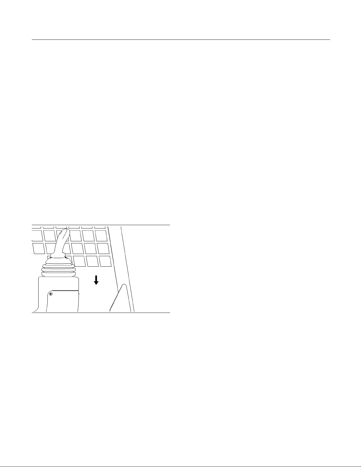
Mount the fire extinguisher on the left side of the cab
floor in f
control. Consult your Caterpillar dealer for the proper
procedure for mounting the fire extinguisher.
ront of the console for the speed/direction
g00929625
i01122596
Electrical Storm Injury
Prevention
SMCS Code: 7000
When lightning is striking in the vicinity of the
machine, the operator should never attempt the
following procedures:
Make sure that the machine is equipped with a
lighting system that is adequate for the job conditions.
Make sure that all machine lights are working
properly.
Before you start the engine and before you move the
machine, make sure that no one is underneath the
machine, around the machine, or on the machine.
Make sure that the area is free of personnel.
i01027818
Engine Starting
SMCS Code: 1000; 7000
If a warning tag is attached to the start switch or to
the controls, do not start the engine. Also, do not
move any controls.
Move all hydraulic controls to the HOLD position
before you start the engine.
Diesel engine exhaust contains products of
combustion which can be harmful to your health.
Always start the engine in a well ventilated area.
Always operate the engine in a well ventilated area.
If you are in an enclosed area, vent the exhaust to
the outside.
Mount the machine.
•
Page 28

28 SEBU7494-06
Safety Section
Before Operation
i01545253
Before Operation
SMCS Code: 7000
A video tape is a
format for the machine. Contact your Caterpillar
dealer in order to obtain a copy of Skid Steer Safety
and Operating
should be viewed by every person that operates the
machine.
Clear all personnel from the machine and from the
area.
Clear all obstacles from the path of the machine.
Beware of hazards such as wires, ditches, etc.
Make sure that all windows are clean. Secure all
doors in the closed position. Secure the windows in
the open pos
Make sure that the machine horn (if equipped), the
backup alar
devices are working properly.
vailable in English in North American
Tips, AEVN4482. The video tape
ition or in the shut position.
m (if equipped) and all other warning
Carry work tool
back the work tool in order to keep the work tool off
of the ground. Do not go close to the edge of a cliff,
an excavation
If the machine begins to sideslip downward on a
slope, immed
machine backward down the slope.
Avoid any con
machine. The machine can tip when you work on
banks and on slopes. Also, the machine can tip
when you cros
obstacles. Never exceed a slope that is greater than
3 to 1 (18.4 degrees).
Maintain control of the machine. Do not overload the
machine beyond the machine capacity.
Never straddle a wire cable. Never allow personnel
to straddle a wire cable.
Know the maximum dimensions of your machine.
Always keep
(ROPS) installed during machine operation.
s low. Lower the lift arms fully. Tilt
, or an overhang.
iately remove the load and move the
ditions that can lead to tipping the
s ditches, ridges or other unexpected
the Rollover Protective Structure
Fasten the s
eat belt securely. Lower the armrest.
i01762042
Operation
SMCS Code: 7000
Only operate the machine while you are in the seat.
The seat belt must be fastened while you operate the
machine. Only operate the controls while the engine
is running.
Beforeyoumovethemachine,youmustbecertain
that no one will be endangered.
While you operate the machine and the work tool
slowly in an open area, check for proper operation of
all controls and all protective devices.
Do not allow riders on the machine.
Note any needed repairs during machine operation.
Report any needed repairs.
Use only Caterpillar Approved Work Tools on this
machine. Obey all the lift restrictions. Refer to
Operation and Maintenance Manual, “Caterpillar
Approved Work Tools” for the approved work tools
and the lift restriction information.
Machine Ope
machine must function satisfactorily in the anticipated
ambient temperature limits that are encountered
during ope
will effect the safe operation of the machine to
be considered are 0-100% relative humidity for
−32 °C (−25
unless otherwise specified in marketing functional
specification.
Observe any local government regulations when you
use the machine to lift heavy objects.
rating Temperature Range. The
ration. The minimum limits of items that
°F) to 43 °C (109.4 °F) temperatures
i01115299
Work Tools
SMCS Code: 6700
Only use work tools that are approved by Caterpillar
for use on Caterpillar machines. Refer to the
Operation and Maintenance Manual, “Caterpillar
Approved Work Tools”.
If you are in doubt about the compatibility of a
particular work tool with your machine, consult your
Caterpillar dealer.
Make sure that all necessary guarding is in place on
the host machine and on the work tool.
Page 29

SEBU7494-06 29
Safety Section
Parking
Keep all window
machine. Always wear protective glasses. Always
wear the protective equipment that is recommended
in the work too
protective equipment that is required for the operating
environment.
To prevent personnel from being struck by flying
objects, ensure that all personnel are out of the work
area.
While you are performing any maintenance, any
testing, or a
clear of the following areas: cutting edges, pinching
surfaces, and crushing surfaces.
s and doors closed on the host
l’s operation manual. Wear any other
ny adjustments to the work tool stay
i01487624
Parking
SMCS Code: 7000
Park on a level surface. If you must park on a grade,
chock the machine.
1. Move the speed/direction control lever slowly to
the HOLD position in order to stop the machine.
2. Move the governor control lever to the LOW IDLE
position.
3. Lower the loader arms and tilt the linkage so that
the work tool rests firmly on the ground.
4. Stop the engine. Keep the armrest in the
LOWERED position.
5. Turn the engine start switch key to the ON
position. Push the parking brake switch.
i01329161
Equipment Lowering with
Engine Stoppe
SMCS Code: 7000
Before lowering any equipment with the engine
stopped, clear the area around the equipment of
all personnel
the type of equipment to be lowered. Keep in mind
most systems use a high pressure fluid or air to
raise or lowe
high pressure air , hydraulic, or some other media
to be released in order to lower the equipment.
Wear appropr
follow the established procedure in the Operation
and Maintenance Manual, “Equipment Lowering with
Engine Stop
manual.
. The procedure to use will vary with
r equipment. The procedure will cause
iate personal protective equipment and
ped” in the Operation Section of the
d
i01879541
Sound Information and
Vibration Informa tion
SMCS Code: 7000
Sound Performance for Machines
that are Of
Countries and in Coun tries that
Adopt the EU Directives
The opera
according to dynamic test procedures and conditions
that are specified in “ISO 6396”.
fered in European Union
tor sound pressure levels are measured
6. Move all hydraulic control levers while you are
pressing several times on each side of the
auxiliary hydraulic control (if equipped) and the
high flow control (if equipped) in order to relieve
hydraulic pressure.
7. Move the hydraulic control levers to the HOLD
position.
8. TurntheenginestartswitchkeytoOFFposition
and remove the key.
Hearing protection may be required under the
following conditions:
The machine is operated with an open operator
•
station.
The windows and doors are not properly
•
maintained.
The machine is operated for extended periods.
•
The mach
•
Machines that are manufactured by Caterpillar
meet the
that are specified in the European Directives. The
EuropeanDirectivesarenotedontheCertificateof
Conform
ine is operated in a noisy environment.
criteria for exterior sound power levels
ance and the accompanying label.
Page 30

30 SEBU7494-06
Safety Section
Guards
The interior so
and 287 machines. The interior sound power level is
89 dB(A) for the 247, 257 and 267 machines. The
exterior soun
are measured according to the test procedures and
conditions that are specified in “2000/14/EC”.
und power level is 84 dB(A) for the 277
d power level is 106 dB(A). These levels
Machine Vibration Levels
The hands and arms are subject to a weighted root
mean square acceleration that is 2.5 m/s
The whole body is subject to a weighted root mean
square acceleration that is 0.6 m/s
The measurements are obtained on a representative
machine by using the procedures that are in the
following st
“ISO 2631/1”
•
“ISO 5349”
•
“SAE J1166”
•
andards:
2
2
(2.3 ft/s2).
(8.2 ft/s2).
i01992325
Guards
(Operator Protection)
SMCS Code: 7
There are different types of guards that are used to
protect the
application determines the type of guard that should
be used.
A daily inspection of the guards is required in order to
check for structures that are bent, cracked or loose.
Never oper
The operator becomes exposed to a hazardous
situation
operating techniques are used. This situation can
occur even though a machine is equipped with an
appropria
operating procedures that are recommended for your
machine.
150-MCH; 7325
operator. The machine and the machine
ate a machine with a damaged structure.
if the machine is used improperly or if poor
te protective guard. Follow the established
Rollover Protective Structure
(ROPS), Falling Object Protective
Structure (FOPS) or Tip Over
Protection Structure (TOPS)
The ROPS/FOPS Structure (if equipped) on your
machine is specifically designed, tested and certified
for that machine. Excavators are not equipped
with ROPS structures. Any alteration or any
modification to the ROPS/FOPS Structure could
weaken the structure. This places the operator
into an unprotected environment. Modifications or
attachments that cause the machine to exceed the
weight that is stamped on the certification plate also
place the operator into an unprotected environment.
Excessive weight may inhibit the brake performance,
the steering performance and the ROPS. The
protection that is offered by the ROPS/FOPS
Structure will be impaired if the ROPS/FOPS
Structure has structural damage. Damage to the
structure can be caused by an overturn, a falling
object, a collision, etc.
Do not mount items (fire extinguishers, first aid
kits, work lights, etc) by welding brackets to the
ROPS/FOPS Structure or by drilling holes in the
ROPS/FOPS Structure. Welding brackets or drilling
holes in the ROPS/FOPS Structures can weaken
the structures. Consult your Caterpillar dealer for
mounting guidelines.
The Tip Over Protection Structure (TOPS) is
another type of guard that is used on mini hydraulic
excavators. This structure protects the operator in
the event of a tipover. The same guidelines for the
inspection, the maintenance and the modification of
the ROPS/FOPS Structure are required for the Tip
Over Protection Structure.
Other Guards (If Equipped)
Protection from flying objects and/or falling objects is
required for special applications. Logging applications
and demolition applications are two examples that
require special protection.
A front guard needs to be installed when a work
tool that creates flying objects is used. Mesh
front guards that are approved by Caterpillar or
polycarbonate front guards that are approved by
Caterpillar are available for machines with a cab or
an open canopy. On machines that are equipped with
cabs, the windshield should also be closed. Safety
glasses are recommended when flying hazards exist
for machines with cabs and machines with open
canopies.
If the work material extends above the cab, top
guards and front guards should be used. Typical
examples of this type of application are listed below:
Page 31

SEBU7494-06 31
Safety Section
Guards
Demolition app
•
Rock q uarries
•
Forestry products
•
Additional gu
applications or work tools. The Operation and
Maintenance Manual for your machine or your
work tool will
guards. Consult your Caterpillar dealer for additional
information.
lications
ards may be required for specific
provide specific requirements for the
Page 32
32 SEBU7494-06
Product Information Section
General Information
Product Information Section
General Information
i01896611
Rated Load
SMCS Code: 6001; 6136; 6542; 7000
Bucket Rated Load
Failure to comply to the rated load can cause possible personal injury or property damage. Review
the rated load of a particular work tool before performing any operation. Make a djustments to the
rated load as necessary for non-standard configurations.
The correspond
bucket at maximum lift height and at a 40 degree
dump angle. The reach is given for each bucket
at maximum lif
angle. Clearance is measured from the ground to the
bucket edge in order to dump the load. The reach is
measured fro
edge.
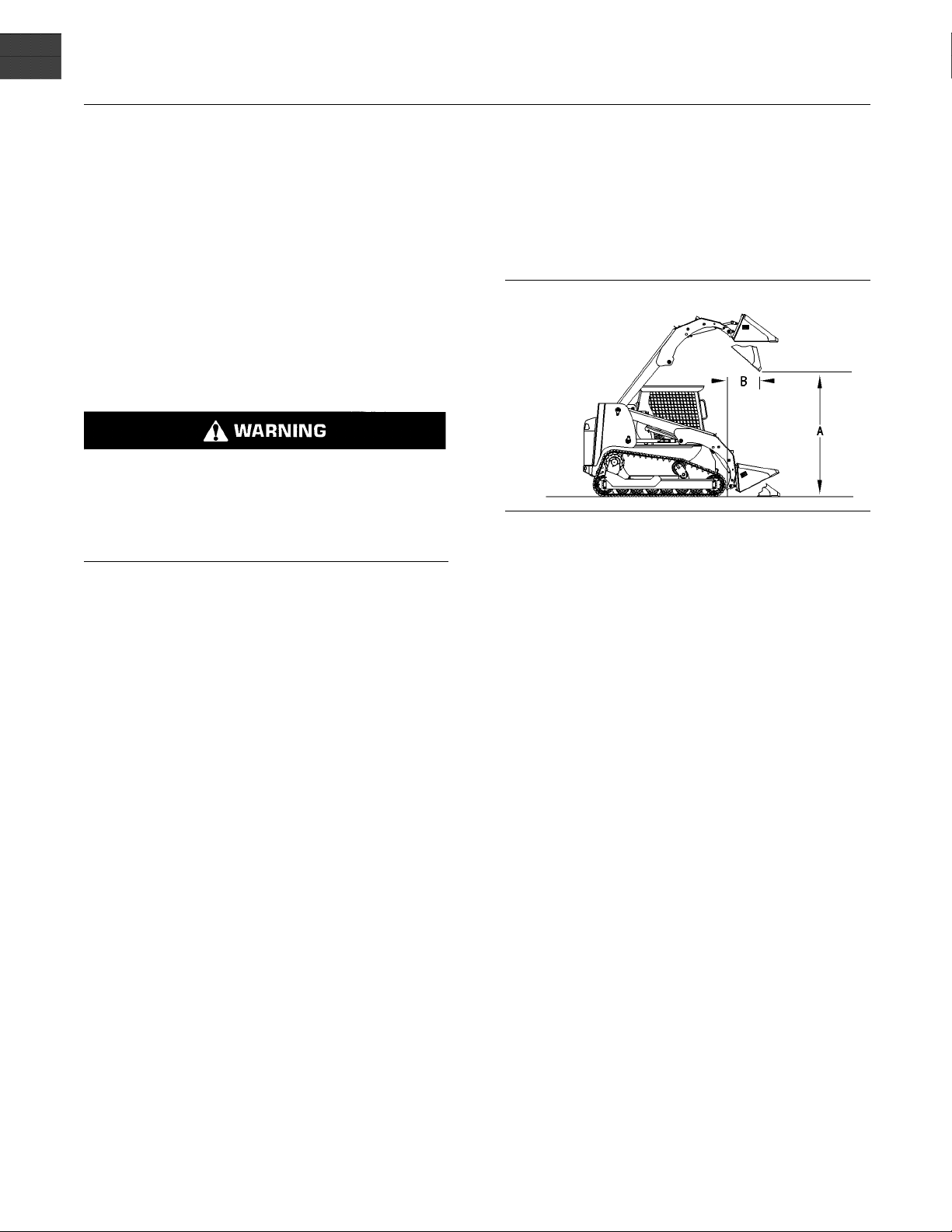
Illustration 14
Dimension (A) represents the dump clearance. Dimension (B)
represents the reach.
ing dump clearance is given for each
t height and at a 40 degree dump
m the front of the track to the bucket
g00777496
Note: Ratedloadsshouldbeusedasaguide.
Attachments, uneven ground conditions, soft ground
conditions, or poor ground conditions have effects on
rated loads. The operator is responsible for being
aware of these effects.
Rated loads are based upon a standard machine with
the following conditions:
lubricants
•
full fuel tank
•
75 kg (165 lb) operator
•
Rated loads will vary with different attachments.
Contact your Caterpillar dealer regarding the rated
load for specific attachments.
The rated operating load for skid steer loaders that
are equipped with rubber tires is defined by the SAE
standard “J818” (May 1987) and by the ISO 5998
(1986) as 50% of the full static tipping load on a
hard, smooth, level surface. The rated operating
load for machines that are equipped with steel tracks
is defined by the SAE standard “J818” (May 1987)
and by the ISO 5998 (1986) as 35% of the full static
tipping load on a soft, less smooth or level surface.
The following tables provide the rated operating
capacities (R.O.C) for the standard machine
configuration with a bucket.
Page 33

SEBU7494-06 33
Product Information Section
General Information
Table 1
General Purpose Buckets
Part Number 165-6152 165-6153 165-6154 199-7720
247
257
267
Width
1524 mm
(60 inch)
Rated Volume 0.36 m3(0.40 yd3) 0.40 m3(0.44 yd3) 0.44 m3(0.48 yd3)
Bucket Weight 200kg(441lb) 216 kg (476 lb) 224 kg (494 lb) 245 kg (540 lb)
Models
R.O.C
35%
R.O.C
50%
R.O.C
35%
R.O.C
50%
R.O.C
35%
620 kg (1366 lb) 613 kg (1351 lb) 611kg(1347lb) 605kg(1333lb)
887 kg (1955 lb) 877 kg (1933 lb) 873kg(1924lb) 865kg(1906lb)
738 kg (1627 lb) 732 kg (1613 lb) 729kg(1607lb) 723kg(1593lb)
1055 kg (2325 lb) 1046 kg (2306 lb) 1042 kg (2297 lb)
N/A N/A 1045 kg (2304 lb)
1676 mm
(66 inch)
1828 mm
(72 inch)
1981 mm
(78 inch)
0.48 m
(0.53 yd3)
1034 kg
(2279 lb)
1036 kg
(2284 lb)
3
1480 kg
(3263 lb)
1042 kg
(2297 lb)
1488 kg
(3280 lb)
1142 kg
(2517 lb)
1631 kg
(3595 lb)
625 mm (2
.1 ft)
277
287
247
257
267 and 277
R.O.C
50%
R.O.C
35%
R.O.C
50%
R.O.C
35%
R.O.C
50%
N/A N/A 1493 kg (3291 lb)
N/A N/A 1051 kg (2317 lb)
N/A N/A 1501 kg (3309 lb)
N/A N/A 1148 kg (2530 lb)
N/A N/A 1640 kg (3615 lb)
(B) 737 mm (2.4 ft) 739 mm (2.4 ft) 739mm(2.4ft) 741 mm (2.4 ft)
(B) 900 mm (3.0 ft) 902 mm (3.0 ft) 903mm(3.0ft) 905 mm (3.0 ft)
(B) N/A N/A 625 mm (2
.1 ft)
287 (B) N/A N/A 988mm(3.2ft) 990 mm (3.2 ft)
247
(A) 1935 mm (6.3 ft) 1934 mm (6.3 ft) 1934 mm (6.3 ft)
257 (A) 2268 mm (7.4 ft) 2267 mm (7.4 ft) 2266 mm (7.4 ft)
267 and 277
(A) N/A N/A 2347 mm (7.7 ft)
287 (A) N/A N/A 2350 mm (7.7 ft)
1933 mm
(6.3 ft)
2265 mm
(7.4 ft)
2347 mm
(7.7 ft)
2349 mm
(7.7 ft)
Page 34
34 SEBU7494-06
Product Information Section
General Information
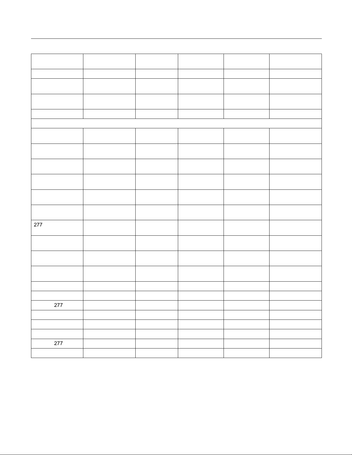
Table 2
Multipurpose
Buckets
Part Number
Width 1524 mm
Rated Volume 0.30 m
Bucket Weight
Models
247
R.O.C
35%
R.O.C
50%
257
R.O.C
35%
R.O.C
50%
267
R.O.C
35%
R.O.C
50%
277
R.O.C
35%
R.O.C
50%
287
R.O.C
35%
R.O.C
50%
247
(B) 752 mm (2.
257 (B) 919 mm (3.0 ft) 922 mm (3.0 ft) 925mm(3.0ft) 927 mm (3.0 ft)
267 and 277 (B) N/A N/A 628mm(2.1ft) 628 mm (2.1 ft)
287 (B) N/A N/A 1009 mm (3.3 ft) 1012 mm (3.3 ft)
247
257
267 and 277
287
(A) 1922 mm (6.3 ft) 1921 mm (6.3 ft) 1920 mm (6.3 ft) 1919 mm (6.3 ft)
(A) 2249 mm (7.4 ft) 2247 mm (7.4 ft) 2245 mm (7.4 ft) 2244 mm (7.4 ft)
(A) N/A N/A 2340 mm (7.7 ft) 2340 mm (7.7 ft)
(A) N/A N/A 2334 mm (7.7 ft) 2299 mm (7.5 ft)
154-5004 154-5008 154-5010 199-8320
(60 inch)
1676 mm
(66 inch)
3
0.34 m3(0.37 yd3) 0.37 m3(0.48 yd3) 0.40 m3(0.44 y d3)
1829 mm
(72 inch)
1981 mm (78 inch)
(0.33 yd3)
331 kg (730 lb) 349kg(769lb) 368kg(811lb) 384 kg (847 lb)
569 kg (1254 lb) 563kg(1241lb) 555 k g (1223 lb) 552kg(1216lb)
814 kg (1794 lb) 803kg(1770lb) 794 k g (1750 lb) 789kg(1739lb)
686 kg (1512
lb)
679kg(1496
lb)
672 kg (1481
lb)
669kg(1474
lb)
981 kg (2162 lb) 970kg(2138lb) 961 k g (2118 lb) 956kg(2107lb)
N/A N/A 986 kg (2174 lb) 979kg(2158lb)
N/A N/A 1409 kg (3106 lb) 1398 kg (3082 lb)
N/A N/A 992 kg (218
7lb)
984kg(216
9lb)
N/A N/A 1417 kg (3124 lb) 1406 kg (3100 lb)
N/A N/A 1085 kg (2392 lb) 1084 kg (2389 lb)
N/A N/A 1550 kg (3417 lb) 1549 kg (3414 lb)
5 ft)
753 mm (2.
5 ft)
755 mm (2.
5 ft)
757 mm (2.
5 ft)
Page 35
SEBU7494-06 35
Product Information Section
General Information
Table 3
Dirt Buckets
165-6155 165-6156 165-6157 188-3526
(54 inch)
30 m3(33 yd3)
1524 mm
(60 inch)
3
0.34 m
(0.37 yd3)
1676 mm (66 inch)
0.37 m3(0.40 y d3)
1829 mm
(72 inch)
0.41 m
3
(0.45 yd3)
131 kg (289 lb) 141 kg (311 lb) 166kg(366lb) 179kg(395lb)
662 kg (1459 lb) 657 kg (1448 lb) 649kg(1430lb)
646 kg
(1424 lb)
947 kg (2087 lb) 939 kg (2070 lb) 928kg(2045lb)
923 kg
(2034 lb)
782 kg (1724 lb) 777 kg (1712 lb) 769kg(1695lb)
764 kg
(1684 lb)
1118 kg
(2464 lb)
N/A N/A N/A
1111 k g ( 2449 lb) 1099 kg (2422 lb) 1092 kg
(2407 lb)
1086 kg
(2394 lb)
N/A N/A N/A
1552 kg
(3422 lb)
N/A N/A N/A
1092 kg
(2407 lb)
N/A N/A N/A 1560 kg
(3439 lb)
N/A N/A N/A
1196 k g
(2636 lb)
N/A N/A N/A
1709 kg
(3767 lb)
697 mm
(2.3 ft)
862 mm
(2.8 ft)
586 mm
(1.9 ft)
947 mm
(3.1 ft)
1971 mm
(6.5 ft)
2309 mm
(7.6 ft)
2383 mm
(7.8 ft)
2392 mm
(7.8 ft)
Models
247
257
267
277
287
247
257
267 and 277
287
247
257
267 and 277
287
Part Number
Width 1372 mm
Rated Volume
Bucket Weight
R.O.C
35%
R.O.C
50%
R.O.C
35%
R.O.C
50%
R.O.C
35%
R.O.C
50%
R.O.C
35%
R.O.C
50%
R.O.C
35%
R.O.C
50%
(B) 692 mm (2.3 ft) 693 mm (2.3 ft) 695mm(2.3ft)
(B) 856 mm (2.8 ft) 857 mm (2.8 ft) 860mm(2.8ft)
(B) N/A N/A N/A
(B) N/A N/A N/A
(A) 1974 mm (6.5 ft) 1973 mm (6.5 ft) 1972 mm (6.5 ft)
(A) 2313 mm (7.6 ft) 2312 mm (7.6 ft) 2310 mm (7.6 ft)
(A) N/A N/A N/A
(A) N/A N/A N/A
Page 36

36 SEBU7494-06
Product Information Section
General Information
Table 4
Utility Bucket
Models
247
257
267
277
287
247
257
267 and 277
287
247
257
267 and 277
287 (A) N/A N/A 2321 mm (7.6 ft)
s
Part Number
Width
Rated Volume
165-8835 165-8746 165-8778
1524 mm (60 inch) 1676 mm (66 inch) 1829 mm (72 inch)
0.42 m3(0.46
yd
3
)
0.47 m3(0.51
yd
3
)
0.51 m3(0.66
yd
3
)
Bucket Weight 211kg(465lb) 226 kg (498 lb) 240kg(529lb)
R.O.C
620 kg (1366
lb)
614 kg (1353
lb)
610kg(1344
lb)
35%
R.O.C
886 kg (1953 lb) 878 kg (1935 lb) 872kg(1922lb)
50%
R.O.C
738 kg (1627 lb) 733 kg (1615 lb) 728kg(1604lb)
35%
R.O.C
1055 kg (2325 lb) 1048 kg (2310 lb) 1041 kg (2295 lb)
50%
R.O.C
N/A N/A 1044 kg (230
2lb)
35%
R.O.C
N/A N/A 1492 kg (3289 lb)
50%
R.O.C
N/A N/A 1050 kg (2315 lb)
35%
R.O.C
N/A N/A 1500 kg (3307 lb)
50%
R.O.C
N/A N/A 1150 kg ( 25
35 lb)
35%
R.O.C
N/A N/A 1644 kg (3624 lb)
50%
(B) 772 mm (2.5 ft) 775 mm (2.5 ft) 775mm(2.5ft)
(B) 934 mm (3.0 ft) 936 mm (3.1 ft) 937mm(3.1ft)
(B) N/A N/A 658mm(2.2ft)
(B) N/A N/A 1023 mm (3.3 ft)
(A) 1909 mm (6.3 ft) 1909 mm (6.3 ft) 1908 mm (6.3 ft)
(A) 2239 mm (7.3 ft) 2237 mm (7.3 ft) 2236 mm (7.3 ft)
(A) N/A N/A 2322 mm (
7.6 ft)
Page 37
SEBU7494-06 37
Product Information Section
General Information
Table 5
Light Material
Models
247
257
267
277
287
247
257
267 and 277
287
247
257
267 and 277
287 (A) 2290 mm (7.5 ft) 2289 mm (7.5 ft)
Buckets
Part Number
Width
Rated Volume
164-7416 167-7417
1829 mm (72 inch) 1981 mm (78 inch)
3
)
0.69 m3(0.90
yd
0.75 m3(0.98
yd
Bucket Weight 257 kg (566 lb) 272 kg (600 lb)
R.O.C
644 kg (1419
lb)
639 kg (1408
lb)
35%
R.O.C
920 kg (2028 lb) 913 kg (2012 lb)
50%
R.O.C
767 kg (1690 lb) 762 kg (1679 lb)
35%
R.O.C
1096 kg (2416 lb) 1089 kg (2400 lb)
50%
R.O.C
1093 kg (241
0lb)
1088 kg (239
9lb)
35%
R.O.C
1562 kg (3444 lb) 1554 kg (3426 lb)
50%
R.O.C
1099 kg (2423 lb) 1094 kg (2412 lb)
35%
R.O.C
1570 kg (3461 lb) 1563 kg (3446 lb)
50%
R.O.C
1216 kg (26
80 lb)
1210 kg (26
67 lb)
35%
R.O.C
1738 kg (3831 lb) 1729 kg (3811 lb)
50%
(B) 809 mm (2.7 ft) 810 mm (2.7 ft)
(B) 969 mm (3.2 ft) 972 mm (3.2 ft)
(B) 690 mm (2.3 ft) 690 mm (2.3 ft)
(B) 1055 mm (3.5 ft) 1057 mm (3.5 ft)
(A) 1880 mm (6.2 ft) 1879 mm (6.2 ft)
(A) 2204 mm (7.2 ft) 2202 mm (7.2 ft)
(A) 2294 mm (
7.5 ft)
2294 mm (
7.5 ft)
3
)
Page 38

38 SEBU7494-06
Product Information Section
General Information
Table 6
Industrial Grapple Buckets
Models
247 R.O.C
257
267 R.O.C
277
287 R.O.C
247
257
267 and 277
287
247
257 (A) 2246 mm (7.4 ft) 2245 mm (7.4 ft) 2243 mm (7.4 ft)
267 and 277 (A) 2348 mm (7.7 ft) 2348 mm (7.7 ft) 2348 mm (7.7 ft)
287 (A) 2338 mm (7.7 ft) 2337 mm (7.7 ft) 2336 mm (7.7 ft)
(1)
The rated capacity is c alculated with a full bucket of dirt. Grasping objects with the grapple will lower the rated capacity.
(1)
Part Number
157-7223 157-7224 157-7225
Width 1524 mm (60 inch) 1676 mm (66 inch) 1829 mm (72 inch)
Bucket Weigh
t
398 kg (877 lb) 413 kg (910 lb) 427kg(941lb)
588 kg (1296 lb) 582 kg (1283 lb) 577kg(1272lb)
35%
R.O.C
840 mm (2.8 ft) 832 mm (2.7 ft) 825mm(2.7ft)
50%
R.O.C
709 kg (1563 lb) 703 kg (1549 lb) 698kg(1538lb)
35%
R.O.C
1013 kg (2233 lb) 1005 kg (2215 lb) 998kg(2200lb)
50%
1031 kg (2273 lb) 1026 kg (2262 lb) 1020 kg (2249 lb)
35%
R.O.C
1473 kg (3247 lb) 1465 kg (3230 lb) 1458 kg (3214 lb)
50%
R.O.C
1037 kg (2286 lb) 1031 kg (2273 lb) 1026 kg (2262 lb)
35%
R.O.C
1481 kg (3265 lb) 1473 kg (3247 lb) 1466 kg (3232 lb)
50%
1147 kg (2528 lb) 1142 kg (2517 lb) 1136 kg (2504 lb)
35%
R.O.C
1639 kg (3613 lb) 1631 kg (3595 lb) 1624 kg (3580 lb)
50%
(B) 760 mm (2.5 ft) 762 mm (2.5 ft) 763mm(2.5ft)
(B) 935 mm (3.0 ft) 937 mm (3.1 ft) 939mm(3.1ft)
(B) 628 mm (2.1 ft) 628 mm (2.1 ft) 628mm(2.1ft)
(B) 1019 mm (3.3 ft) 1021 mm (3.3 ft) 1022 mm (3.4 ft)
(A) 1924 mm (6
.3 ft)
1924 mm (6
.3 ft)
1923 mm (6
.3 ft)
Page 39

SEBU7494-06 39
Product Information Section
General Information
Table 7
Utility Grapple Buckets
Models
247 R.O.C
257
267 R.O.C
277
287 R.O.C
247
257
267 and 277
287
247
257 (A) 2226 mm (7.3 ft) 2225 mm (7.3 ft)
267 and 277 (A) 2322 mm (7.6 ft) 2322 mm (7.6 ft)
287 (A) 2315 mm (7.6 ft) 2314 mm (7.6 ft)
(1)
Part Number
Width 1676 mm (66 inch) 1829 mm (72 inch)
Bucket Weigh
35%
R.O.C
50%
R.O.C
35%
R.O.C
50%
35%
R.O.C
50%
R.O.C
35%
R.O.C
50%
35%
R.O.C
50%
(B) 783 mm (2.6 ft) 785 mm (2.6 ft)
(B) 951 mm (3.1 ft) 953 mm (3.1 ft)
(B) 658 mm (2.2 ft) 658 mm (2.2 ft)
(B) 1035 mm (3.4 ft) 1037 mm (3.4 ft)
(A) 1903 mm (6
t
165-8729 165-8730
330 kg (728 lb) 344 kg (758 lb)
583 kg (1285 lb) 578 kg (1274 lb)
833 kg (1836 lb) 826 kg (1821 lb)
701 kg (1545 lb) 696 kg (1534 lb)
1002 kg (2209 lb) 995 kg (2193 lb)
1016 kg (2240 lb) 1012 kg (2231 lb)
1452 kg (3201 lb) 1445 kg (3186 lb)
1022 kg (2253 lb) 1017 kg (2242 lb)
1460 kg (3219 lb) 1453 kg (3203 lb)
1123 kg (2475 lb) 1118kg(2464lb)
1605 kg (3538 lb) 1598 kg (3522 lb)
.2 ft)
1903 mm (6
.2 ft)
Rated Loads for Forks
Failure to comply to the rated load can cause possible personal injury or property damage. Review
the rated load of a particular work tool before performing any operation. Make a djustments to the
rated load as necessary for non-standard configurations.
Note: Rated loads should be used as a guide.
Attachments, uneven ground conditions, soft ground
conditions, or poor ground conditions have effects on
rated loads. The operator is responsible for being
aware of these effects.
The rated operating load is defined by SAE J1197
FEB 91 and EN474. The rated operating load is the
least amount of weight of the following conditions:
35% of the full static tipping load on a soft, less
•
smooth or level surface or 50% of the full static
tipping load on a hard, smooth, level surface
100% of the lifting capacity
•
Page 40

40 SEBU7494-06
Product Information Section
General Information
Illustration 15
Dimension (A) represents the maximum fork height. Dimension (B)
represents the load center. Dimension (C) represents the reach.
Dimension (D) represents the fork tine length.
g00777498
The maximum fork height (ground to top face of
fork) is given for a pallet fork that is horizontal at
maximum lift height. The reach (front of the tracks to
the front face of the fork) is given for a pallet fork that
is horizontal maximum reach.
The following tables provide the rated operating
capacities (R.O.C) for the standard machine
configuration that is equipped with the following
items:
full fuel tank
•
75 kg (165 lb) operator
•
Caterpillar fork
•
Page 41

SEBU7494-06 41
Product Information Section
General Information
Table 8
Rated Operating Load with a Pallet Fork
Part Number
Weight 184 kg (406 lb) 194 kg (428 lb) 203kg(448lb)
(B) 455 mm (18 inch) 535 mm (21 inch) 610 mm (24 inch)
(D) 910 mm (36 inch) 1070 mm (42 inch) 1220 mm (48 inch)
Models
247 R.O.C
35%
R.O.C
50%
257
267 R.O.C
277
287 R.O.C
247
257
267 and 277
287
247 (A) 2547 mm (8.4 ft) 2546 mm (8.4 ft) 2545 mm (8.4 ft)
257 (A) 2763 mm (9.0 ft) 2762 mm (9.0 ft) 2762 mm (9.0 ft)
267 and 2
287
77
R.O.C
35%
R.O.C
50%
35%
R.O.C
50%
R.O.C
35%
R.O.C
50%
35%
R.O.C
50%
(B) 917 mm (3.0 ft) 917 mm (3.0 ft) 918mm(3.0ft)
(B) 1073 mm (3.5 ft) 1073 mm (3.5 ft) 1073 mm (3.5 ft)
(B) 845 mm (2.8 ft) 845 mm (2.8 ft) 845mm(2.8ft)
(B) 1151 mm (3
(A) 2987 mm (9.8 ft) 2987 mm (9.8 ft) 2987 mm (9.8 ft)
(A) 2855 mm (9.4 ft) 2855 mm (9.4 ft) 2855 mm (9.4 ft)
151-5134 149-1412 161-2437
404 kg (890 lb) 390 kg (859 lb) 377kg(831lb)
577 kg (1272
580 kg (1278 lb) 551 kg (1214 lb) 525kg(1157lb)
829 kg (1827 lb) 787 kg (1735 lb) 751kg(1655lb)
848 kg (1870 lb) 811 kg (1788 lb) 777kg(1713lb)
1212 kg (26
852 kg (1878 lb) 815 kg (1797 lb) 782kg(1724lb)
1217 kg (2683 lb) 1165 kg (2568 lb) 1118 kg (2465 lb)
893 kg (1968 lb) 848 kg (1869 lb) 812kg(1790lb)
1275 kg (28
lb)
72 lb)
10 lb)
.8 ft)
557 kg (1227
1158 kg (25
1212 kg (26
1151 mm (3
lb)
53 lb)
71 lb)
.8 ft)
539kg(1188
1111 kg (24
1161 kg ( 25
1151 mm ( 3
49 lb)
lb)
59 lb)
.8 ft)
Page 42

42 SEBU7494-06
Product Information Section
General Information
Table 9
Rated Operating Load with a Utility Fork
Part Number
Weight 195 kg (430 lb) 217 kg (478 lb)
Width 1676 mm (66 inch) 1829 mm (72 inch)
(B) 314 mm (12 inch) 314 mm (12 inch)
Models
247 R.O.C
35%
R.O.C
50%
257
267 R.O.C
277
287 R.O.C
R.O.C
35%
R.O.C
50%
35%
R.O.C
50%
R.O.C
35%
R.O.C
50%
35%
R.O.C
50%
165-8732 165-8737
420 kg (925 lb) 414 kg (912 lb)
600 kg (1322
628 kg (1384 lb) 622 kg (1371 lb)
897 kg (1977 lb) 889 kg (1959 lb)
900 kg (1984 lb) 894 kg (1971 lb)
1286 kg (28
905 kg (1995 lb) 899 kg (1982 lb)
1293 kg (2851 lb) 1285 kg (2833 lb)
976 kg (2151 lb) 967 kg (2131 lb)
1394 kg (30
lb)
35 lb)
73 lb)
592 kg (1305
1277 kg (28
1381 kg (30
lb)
15 lb)
44 lb)
Rated Load with a M ater ial Handling
Arm
Failure to comply to the rated load can cause possible personal injury or property damage. Review
the rated load of a particular work tool before performing any operation. Make a djustments to the
rated load as necessary for non-standard configurations.
Note: Ratedloadsshouldbeusedasaguide.
Attachments, uneven ground conditions, soft ground
conditions, or poor ground conditions have effects on
rated loads. The operator is responsible for being
aware of these effects.
The maximum placement height (ground line to the
chain hook) is given for the highest position of the
material handling arm. The maximum reach (front
of the machine to the chain hook) is the maximum
horizontal reach of the material handling arm.
The rated operating capacity is the least amount of
weight of the following conditions:
35% of the full static tipping load on a soft, less
•
smooth or level surface or 50% of the full static
tipping load on a hard, smooth, level surface
100% of the lifting capacity
•
The material handling arm has a structural capacity
•
of 907 kg (2000 lb).
The following tables provide the rated operating
capacities (R.O.C.) for the standard machine
configuration that is equipped with the following
items:
full fuel tank
•
75 kg (165 lb) operator
•
Caterpillar Material Handling Arm
•
Page 43

SEBU7494-06 43
Product Information Section
General Information
Illustration 16
Lifting point 1 (1)
Lifting point 2 (2)
Illustration 17
Dimension (A) represents the clearance at the full down position
from Lifting Point 2. Dimension (a) represents the clearance at the
full down position from Lifting Point 1. Dimension (B) represents the
clearance at maximum height from Lifting Point 2. Dimension (b)
represents the clearance at ma ximum height from Lifting Point 1.
Dimension (C) represents the minim um reach from Lifting Point 2.
Dimension (c) represents the minimum reach f rom Lifting Point 1.
Dimension (D) represents the maximum reach from Lifting Point 2.
Dimension (d) represents the maximum reach from Lifting Point 1.
g00668844
g00779834
Page 44

44 SEBU7494-06
Product Information Section
General Information
Table 10
Models Lifting Point 1 (1) Lifting Point 2 (2)
247
257
267
277
287
R.O.C 543 kg (1197 lb) 447 kg (985 lb)
Clearance at Full Down 111 9 mm ( 3.7 ft) 1614 mm (5.3 ft)
Clearance at Maximum
Height
Minimum Reach 653 mm (2.1 ft) 535 mm (1.8 ft)
Maximum Reach
R.O.C 649 kg (1430 lb) 539 kg (1188 lb)
Clearance at Full Down 946 mm (3.1 ft) 1439 mm (4.7 ft)
Clearance at Maximum
Height
Minimum Reach 669 mm (2.2 ft) 547 mm (1.8 ft)
Maximum Reach
R.O.C 711 kg (1567 lb) 698 kg (1538 lb)
Clearance at Full Down 970 mm (3.2 ft) 1460 mm (4.8 ft)
Clearance at Maximum
Height
Minimum Reach 508 mm (1.7 ft) 369 mm (1.2 ft)
Maximum Reach
R.O.C 711 kg (1567 lb) 728 kg (1604 lb)
Clearance at Full Down 970 mm (3.2 ft) 1460 mm (4.8 ft)
Clearance at Maximum
Height
Minimum Reach 508 mm (1.7 ft) 369 mm (1.2 ft)
Maximum Reach
R.O.C 907 kg (1999 lb) 841 kg (1854 lb)
Clearance at Full Down 991 mm (3.3 ft) 1482 mm (4.9 ft)
Clearance at Maximum
Height
Minimum Reach 566 mm (1.9 ft) 436 mm (1.4 ft)
Maximum Reach
3868 mm (12.7 ft) 4312 mm (14.1 ft)
1911 mm (6.3 ft) 2350 mm (7.7 ft)
4246 mm (13.9 ft) 4691 mm (15.4 ft)
1937 mm (6.4 ft) 2369 mm (7.8 ft)
4325 mm (14.2 ft) 4766 mm (15.6 ft)
1760 mm (5.8 ft) 2201 mm (7.2 ft)
4325 mm (14.2 ft) 4766 mm (15.6 ft)
1760 mm (5.8 ft) 2201 mm (7.2 ft)
4340 mm (14.2 ft) 4522 mm (14.8 ft)
1747 mm (5.7 ft) 2193 mm (7.2 ft)
i01881423
Specifications
SMCS Code: 7000
The specifications that are given herein describe
the machine as the machine is manufactured by
Caterpillar Inc. The machine is full of f luids. The
machine is equipped with all options. The weight
does not include the operator, work tools, or other
attachments.
Page 45

SEBU7494-06 45
Product Information Section
General Information
Table 11
247 257 267 277 287
Maximum
Machine
Weight
Overall
Length
Height 2022 mm
3002 kg (6618 lb) 3439 kg (7582 lb) 4089 kg (9015 lb) 4106 kg (9052 lb) 4412 kg (9727 lb)
2701 mm
(106 inch)
(80 inch)
2701 mm
(106 inch)
2022 mm (80 inch)2074 mm (82 inch)2074 mm (82 inch)2123 mm (84 inc
2923 mm
(115 inch)
2923 mm
(115 inch)
2901 mm
(114 inch)
h)
Width 1676 mm
(66 inch)
1676 mm (66 inch) 1974 mm (78 inch) 1974 mm (78 inch) 1962 mm (77 inch)
Page 46

46 SEBU7494-06
Product Information Section
Identification Information
Identification Information
i01946856
Plate Locations and Film
Locations
SMCS Code: 1000; 7000
The Product Identification Number (PIN) will be used
to identify a powered machine that is designed for
an operator to ride.
Caterpillar products such as engines, transmissions
and motorized work tools that are not designed for an
operator to ride are identified by Serial Numbers.
For quick reference, record the identification numbers
in the spaces that are provided below the illustration.
Model ________
•
Power (kW) ________________________________________ _______
•
Weight (kg) _______________________________________________
•
Illustration 20
This plate is located on the left side of the engine block.
Engine Serial Number _____________________________ _______
______________________________________________
g00903003
i01830750
Illustration 18
247, 267, and 277
Illustration 19
257 and 287
g00902931
g00902975
Emissions C
SMCS Code: 1000; 7000; 7405
Note: This information is pertinent in the United
States, in Canada and in Europe.
A typical example is shown.
ertification Film
(1) Machine PIN ____________________________________________
(2) CE Plate
PIN _________________________________________________________
•
Page 47
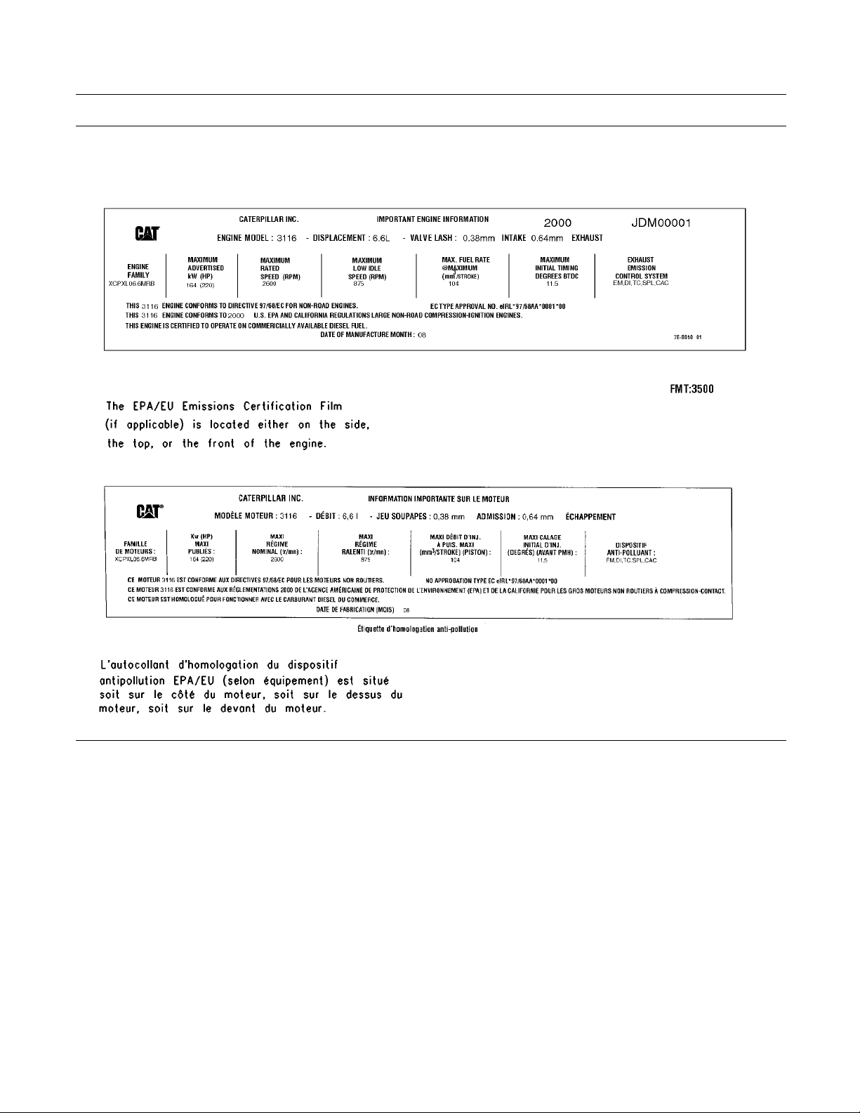
SEBU7494-06 47
Product Information Section
Identification Information
Illustration 21
g00776690
Page 48

48 SEBU7494-06
Operation Section
Before Operation
Operation Section
Before Operation
Mounting and Dismounting
SMCS Code: 7000
ion 22
Illustrat
Typical example
i02189821
g00037860
i01946878
Daily I nspection
SMCS Code: 1000; 7000
NOTICE
Accumulated grease and oil on a machine is a fire hazard. Remove this debris with steam cleaning or high
pressure water, at least every 1000 hours or each time
any significant quantity of oil is spilled on a machine.
Note: For maximum service life of the machine,
make a thorough daily inspection before you operate
the machine. Inspect the machine for leaks. Remove
any debris from the engine compartment and the
undercarriage. Ensure that all guards, covers, and
caps are secured. Inspect all hoses and belts for
damage. Make the needed repairs before you
operate the machine.
Perform the following procedures on a daily basis.
Operation and Maintenance Manual, “Engine Oil
•
Level - Check”
Operation and Maintenance Manual, “Cooling
•
System Level - Check”
Mount the machine and dismount the machine only
at locations that have steps and/or handholds. Before
you mount t
handholds. Inspect the steps and handholds. Make
all necessary repairs.
Face the machine whenever you get on the machine
and whenever you get off the machine.
Maintain a three-point contact with the steps and with
the handholds.
Note: Three-point contact can be two feet and one
hand. Three-point contact can also be one foot and
two hands
Do not mount a moving machine. Do not dismount a
moving ma
not carry tools or supplies when you try to mount the
machine or when you try to dismount the machine.
Use a han
Do not use any controls as handholds when you
enter the operator compartment or when you exit the
operat
Altern
he machine, clean the steps and the
.
chine. Never jump off the machine. Do
d line to pull equipment onto the platform.
or compartment.
ate Exit
Operation and Maintenance Manual, “Radiator
•
Core - Clean”
Operation and Maintenance Manual, “Hydraulic
•
System Oil Level - Check”
Operation and Maintenance Manual, “Engine Air
•
Filter Service Indicator - Inspect”
Operation and Maintenance Manual, “Fuel System
•
Water Seperator - Drain”
Operation and Maintenance Manual, “Axle
•
Bearings - Lubricate”
Operation and Maintenance Manual, “Lift Arm and
•
Cylinder Linkage - Lubricate”
Operation and Maintenance Manual, “Seat Belt -
•
Inspect”
Operation and Maintenance Manual, “Tilt Cylinder
•
Bearings and Bucket Linkage Bearings - Lubricate”
Operation and Maintenance Manual, “Bogie and
•
Idler - Inspect/Replace”
Machines that are equipped with cabs have alternate
For additional information, see Operation and
exits.
Maintenance Manual, “Alternate Exit”.
Operation and Maintenance Manual, “Sprocket
•
Retaining Nuts - Check”
Operation and Maintenance Manual, “Track
•
(Rubber) - Inspect/Replace”
Page 49

SEBU7494-06 49
Operation Section
Before Operation
Operation and M
•
Coupler - Inpsect/Adjust”
Operation and
•
Mounting Bracket - Inspect”
Operation and
•
Alarm - Test”
Refer to the Ma
procedures. Refer to the Maintenance Interval
Schedule for a complete list of scheduled
maintenance
Refer to the following service interval charts
and service i
information.
aintenance Manual, “Quick
Maintenance Manual, “Work Tool
Maintenance Manual, “Backup
intenance Section for the detailed
.
ntervals for additional maintenance
Page 50
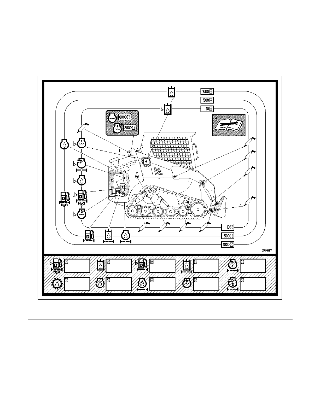
50 SEBU7494-06
Operation Section
Before Operation
247 Service Interval Chart
Illustration 23
g00892512
Page 51
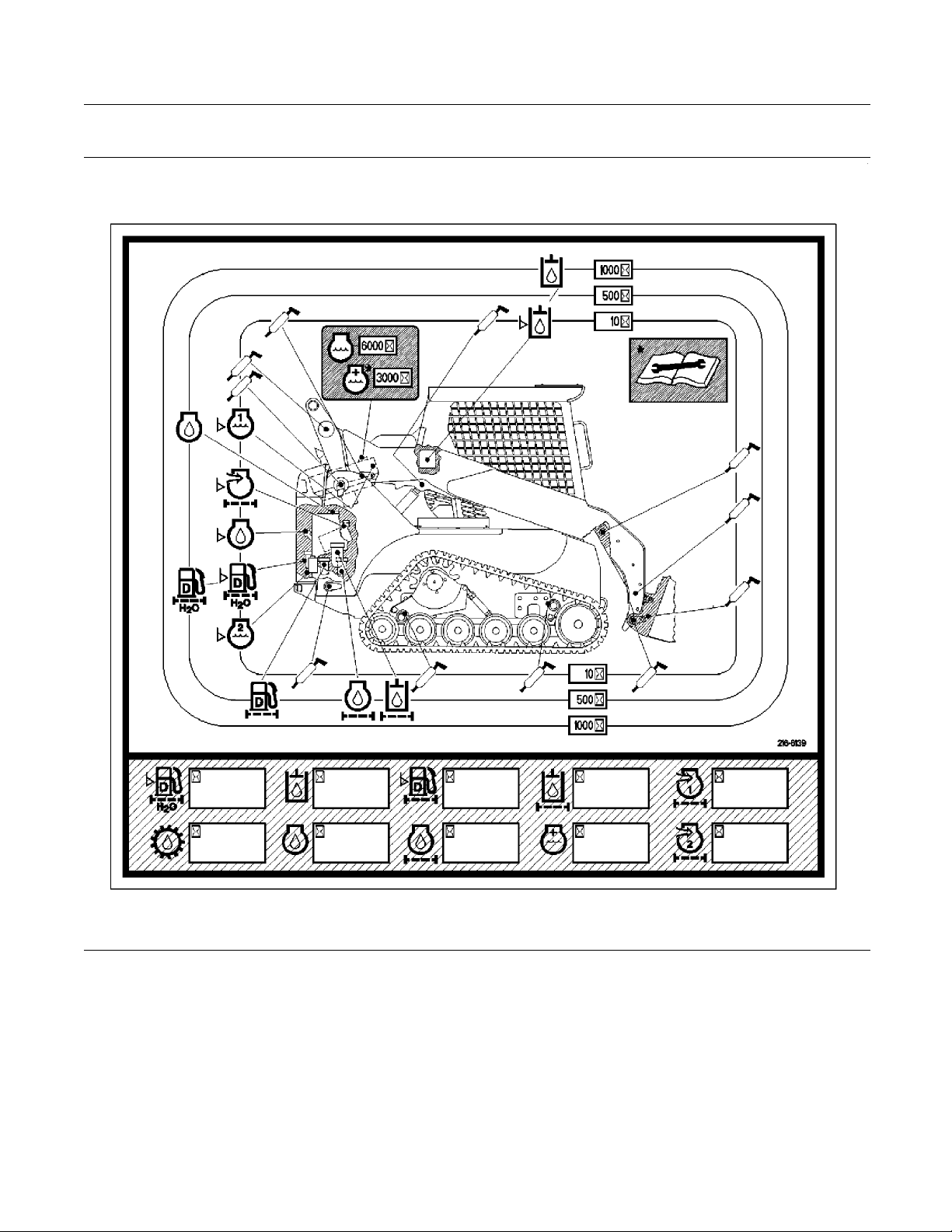
SEBU7494-06 51
Operation Section
Before Operation
257 and 287 Service Interval Chart
Illustration 24
g00892465
Page 52
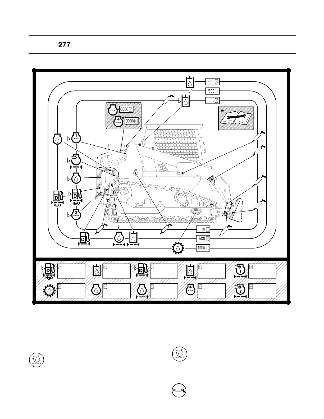
52 SEBU7494-06
Operation Section
Before Operation
267 and 277 Service Interval Chart
Illustration 25
Service Intervals
Engine air filter primary element – Clean
the primary air filter element or replace
the primary air filter element. The air
filter service indicator indicates when servicing is
necessary.
g00785614
Engine air filter secondary element –
Replace the secondary air filter element
with every third change of the primary
air filter element or replace the secondary air filter
element when it is necessary.
Grease zerk – Lubricate the designated
locations after every ten service hours or
at the end of each day.
Page 53

SEBU7494-06 53
Operation Section
Before Operation
Hydraulic oil level check – Check the
hydraulic oil level at the sight gauge after
every ten serv
each day.
Engine oil level check – Check the engine
oil level afte
the end of each day.
Fuel system water separator – Drain
the water sepa
hours or at the end of each day.
Coolant level (radiator) – Check the
coolant level
gauge after every ten service hours or at
the end of each day.
Coolant leve
coolant level in the coolant reservoir after
every ten service hours or at the end of
each day.
Engine Air Filter Service Indicator –
Check the indicator after every ten service
hours or at th
ice hours or at the end of
r every ten service hours or at
rator after every ten service
in the radiator at the sight
l (reservoir) – Check the
e end of each day.
Cooling system coolant – Change the
ELC (Extended Life Coolant) after every
6000 hours or e
Bogie oil level check and Idler oil level
check – Check the oil level in the Bogie
wheel tubes an
every 1000 hours or every year.
very 4 years.
d the Idler wheel tubes after
Engine oil – Change the engine oil after
every 500 service hours or every three
months.
Fuel System Water Separator Element –
Replace the fuel system water separator
element aft
every three months.
Engine oil filter – Change the engine oil
filter afte
three months.
Hydraulic oil filter – Change the hydraulic
oil filter a
every three months.
Diesel fuel filter – Change the fuel filter
after every
months.
Hydraulic oil – Change the hydraulic oil
after every
per year.
r every 500 service hours or every
er every 500 service hours or
fter every 500 service hours or
500 service hours or every three
1000 service hours or one time
Coolant additive – Add the extender to
the extende
service hours or every 2 years.
d life coolant after every 3000
Page 54

54 SEBU7494-06
Operation Section
Machine Operation
Machine Operation
i01850883
Alternate Exit
SMCS Code: 7000
ion 26
Illustrat
The opening in the rear of the machine serves as an
alternate
be removed in order to use the alternate exit.
exit. The window (if equipped) will need to
g00929616
i01822242
Seat Belt
SMCS Code: 7327
Note: This mach
when the machine was shipped from Caterpillar.
At the time of installation, the seat belt and the
instructions
SAE J386 standards. See your Caterpillar dealer for
all replacement parts.
Always check the condition of the seat belt and
the condition of the mounting hardware before you
operate the m
Seat Belt Adj
Non-Retractable Seat Belts
Adjust both ends of the seat belt. The seat belt should
be snug but comfortable.
Lengthening the Seat Belt
ine was equipped with a seat belt
for installation of the seat belt meet the
achine.
ustment for
The window
the top of the window. This will remove the seal that
holds the window in place. When the seal is taken
out, caref
Illustration 27
If the machine is equipped with a cab door, the
opening in the door may serve as an alternate exit.
The window will need to be removed in order to use
the alternate exit.
The window can be removed by pulling on the ring
on the left side of the window. This will remove the
seal that holds the window in place. When the seal is
taken out, carefully remove the window.
can be removed by pulling on the ring at
ully remove the window.
g00929624
Illustration 28
1. Unfasten
Illustration 29
g00100709
the seat belt.
g00932817
Page 55
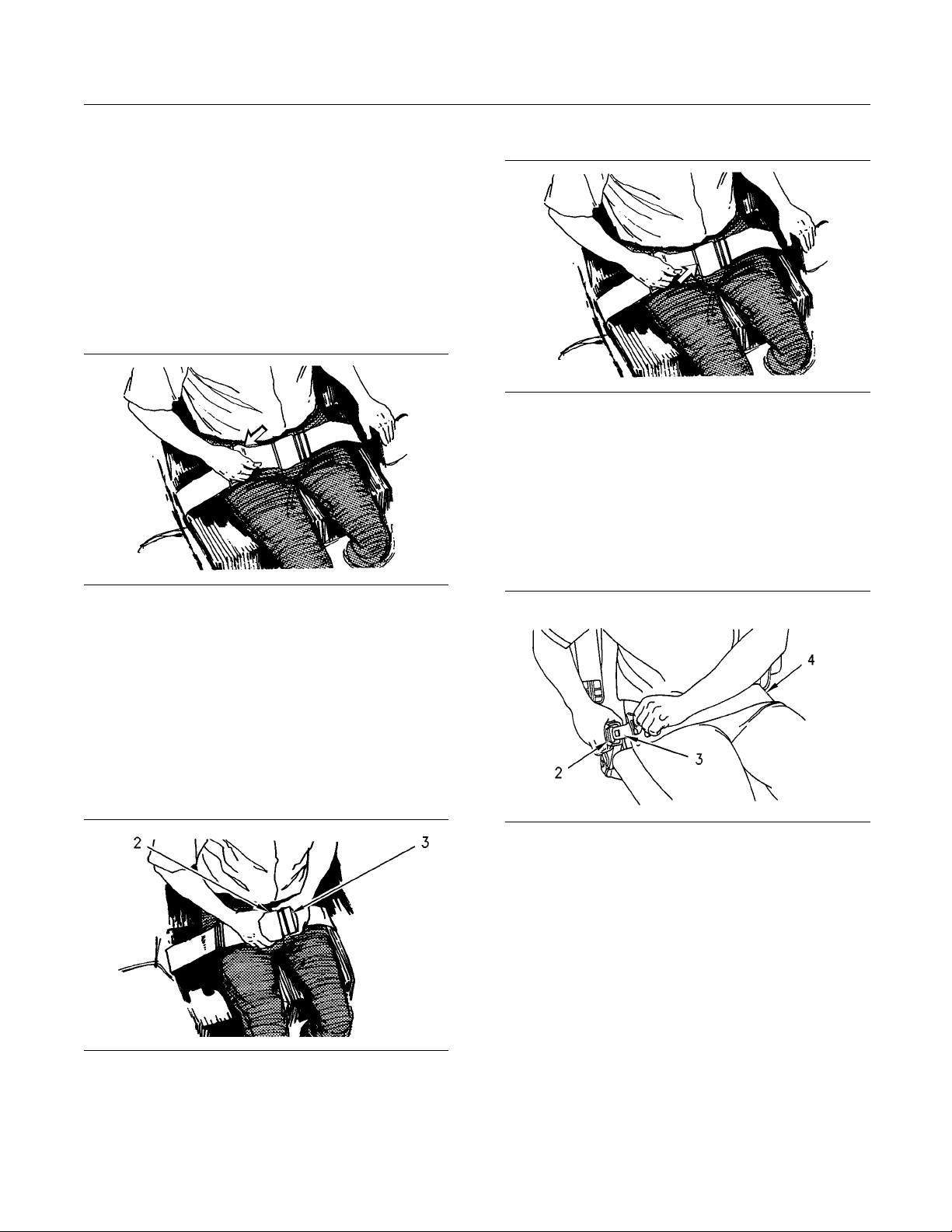
SEBU7494-06 55
Operation Section
Machine Operation
2. To r e m o v e t h e s l
ack in outer loop (1), rotate buckle
(2). This will free the lock bar. This permits the
seat belt to move through the buckle.
3. Remove the slack from the outer belt loop by
pulling on the buckle.
4. Loosen the other half of the seat belt in the same
manner. If the seat belt does not fit snugly with the
buckle in the
center, readjust the seat belt.
Shortening the Seat Belt
Releasing The S
Illustratio
n32
eat Belt
g00100717
Pull up on the release lever. This will release the seat
belt.
Seat Belt Ad
justment for
Retractable Seat Belts
Fastening The Seat Belt
Illustration 30
g00100713
1. Fasten the seat belt. Pull out on the outer belt loop
in order to tighten the seat belt.
2. Adjust the other half of the seat belt in the same
manner.
3. If the seat belt does not fit snugly with the buckle
in the center, readjust the seat belt.
Fastening The Seat Belt
Illustration 33
Pull seat
belt (4) out of the retractor in a continuous
g00867598
motion.
Fasten se
at belt catch (3) into buckle (2). Make sure
that the seat belt is placed low across the lap of the
operator.
The retractor will adjust the belt length and the
retractor will lock in place. The comfort ride sleeve
ow the operator to have limited movement.
will all
Illustration 31
Fasten t
he seat belt catch (3) into the buckle (2).
g00932818
Make sure that the seat belt is placed low across the
lap of the operator.
Page 56

56 SEBU7494-06
Operation Section
Machine Operation
Releasing The S
Illustratio
Push the release button on the buckle in order to
release the s
retract into the retractor.
n34
eat belt. The seat belt will automatically
eat Belt
g00039113
Extension of the Seat Belt
When using r
belt e xtensions, or personal injury or death can
result.
The retractor system may or may not lock up depending on the length of the extension and the
size of the
up, the seat belt will not retain the person.
Longer, no
the non-retractable seat belts are available.
Caterpill
be used with a seat belt extension.
Consult yo
and for information on extending the seat belts.
etractable seat belts, do not use seat
person. If the retractor does not lock
n-retractable seat belts and extensions for
ar requires only non-retractable seat belts to
ur Caterpillar dealer for longer seat belts
i02406630
Operator Controls
SMCS Code: 7300; 7451
Page 57

SEBU7494-06 57
Operation Section
Machine Operation
Illustration 35
(1) Interlock Control
(2) Seat Adjustment
(3) Engine Start S witch
(4) Glow Plug Starting Aid
(5) P arking Brake Control
(6) Governor Control
(7) Accelerator Co ntrol
(8) Speed and Direction Control
(9) Work Tool Control
(10) Work Tool Coupler C ontrol
(11) Horn
(12) Turn Signals
(13) Haza rd Flashers
(14) Roading Lights
(15) F ront Work Lights
(16) Rear Work Lights
(17) B eacon S w itch
(18) Cab D om e Light
(19) Service H our Meter
(20) Fuel Level Gauge
(21) Window Wiper and Window Washer
(22) Hydraulic Shutoff Control
g01005547
(23) Auxiliary Hydraulic Control
(24) Auxiliary Electrical Control
(25) Plugged
(26) Automatic Level Control
(27) Continuous Flow and Interlock Override
(28) Rear Auxiliary Hydraulic Control or
Fourth Func tion Control
(29) Temperature Control
(30) S uspension S eat
(31) Fan S peed Control
(32) Air Conditioning Control
Page 58

58 SEBU7494-06
Operation Section
Machine Operation
Interlock Control (1)
Interlock Control – Move the armrest to the
RAISED position in order to lock out the hydraulic
controls.
Note: When the armrest is moved to the RAISED
position, the parking brake will engage. Move the
armrest to the LOWERED position and push the
switch for the parking brake in order to activate the
hydraulic controls.
Note: When you start the engine, the parking brake
must be disengaged in order for the hydraulic
controls to be activated. If the armrest is raised and
then lowered during operation, you must disengage
the parking brake in order for the hydraulic controls
to be activated.
Seat Adjustment (2)
Seat Adjustment
Engine Start Switch (3)
Parking Brake Control (5)
Parking Brake Control – Press on the
right side of the switch in order to engage
or disengage the parking brake.
Note: The parking brake will engage when the engine
is stopped. The parking brake will engage when
thearmrestismovedtotheRAISEDposition.The
parking brake will engage when the operator leaves
the operator seat for an extended period of time.
Governor Control (6)
Governor Control – Use the governor control when
you want to set a constant engine speed. Move the
lever forward in order to increase engine speed.
Move the lever backward in order to decrease engine
speed.
High Idle
Low Idle
OFF – Insert the engine start switch key
only from the OFF position and remove
the engine start switch key only from the
OFF position. Turn the engine start switch key to
the OFF position in order to stop the engine. In the
OFF position, there is no power to most electrical
circuits on the machine. The cab lights, panel lights,
tail lights, working lights (if equipped) and fuel gauge
light are operational even when the engine start
switch is in the OFF position.
ON – Turn the engine start switch key
clockwise to the ON position in order to
activate all of the cab circuits.
START – Turn the engine start switch key
clockwise to the START position in order to
crank the engine. Release the engine start
switch key after the engine starts and the engine start
switch key returns to the ON position.
Note: If the engine fails to start, the engine start
switch key must be returned to the OFF position in
order to attempt to start the engine again.
Accelerator Control (7)
Accelerator Control – Push down on
the accelerator pedal in order to increase
engine speed. Release the accelerator
pedal in order to decrease engine speed. The
accelerator pedal will return to the setting of the
governor control.
Glow Plug Starting Aid (4)
Glow Plug Starting Aid – Refer to
Operation and Maintenance Manual,
“Engine Starting” for the starting procedure
with glow plugs.
Page 59

SEBU7494-06 59
Operation Section
Machine Operation
Speed and Direction Control (8)
Illustration 36
(1) FORWARD
(2) RIGHT TURN
(3) RIGHT SPOT TURN
(4) REVERSE LEF T TURN
(5) REVERSE
(6) REVERSE R IGH T TURN
(7) LEFT SPOT TURN
(8) LEFT TURN
(9) HOLD
g00741590
When you releas
e the joystick from any position,
the joystick will return to the HOLD position (9). The
machinewillstopmovingwhenthejoystickisinthe
HOLD position
Work Tool Cont
Illustration 38
(1) TILT FORWARD
(2) TILT F ORWARD and RAISE
(3) RAISE
(4) TILT BACK and RAISE
(5) TILT BACK
(6) T ILT BACK and LOWER
(7) LOWER
(8) FLOAT
(9) TILT FORWARD and LO W E R
(10) HOLD
.
rol (9)
g01080546
Illustration 37
g00897879
Two Sp eed – Press the switch on the front of the
joystick in order to activate rabbit mode.
Note: Keep the work tool close to the ground when
you travel in rabbit mode. This will maximize the
stability of the machine.
Note: The backup alarm will sound when you travel
in reverse.
When you release the joystick the joystick will return
to the HOLD position (9). The work tool and loader
arms will stop moving when the joystick is in the
HOLD position.
Note: If the joystick is in the FLOAT detent, the
joystick must be pulled out of the FLOAT position in
order for the joystick to return to the HOLD position.
Page 60
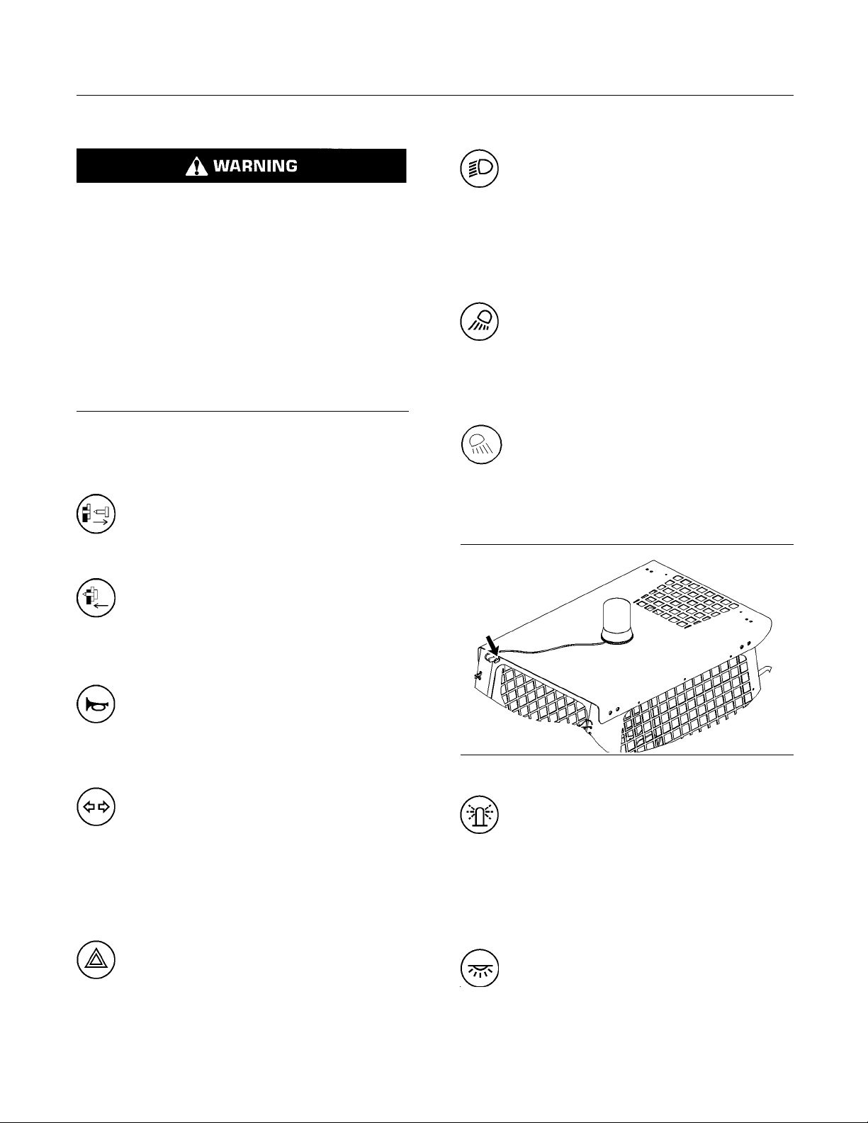
60 SEBU7494-06
Operation Section
Machine Operation
Work Tool Coupler Control (10)
Improper attachment of work tools could result in
injury or death.
Do not operate this machine until you have positive indication that the coupler pins are fully engaged. Check for engagement by:
1. Tilt the work tool down.
2. Put downward pressure on the work tool.
3. Back the machine up and make sure there is
not any movement between the work tool and the
quick coupler assembly.
Work Tool Coupler Control (If Equipped) – The
work tool coupler control controls the engagement
of the coupler pins.
Disengaged – Pull the red button
downward and press the bottom of the
switch. Hold the switch in the downward
position until the coupler pins disengage.
Roading Lights (14)
Roading Lights (If Equipped) – Move
theswitchtothemiddlepositioninorderto
turn on the control panel lights and position
lights. Press on the bottom of the switch in order to
turn on the front low beams. Press on the top of the
switch in order to turn off the lights.
Front Work Lights (15)
Front Work Lights (If Equipped) – Press
theleftsideoftheswitchinordertoturnon
the lights. Press the right side of the switch
in order to turn off the lights.
Rear Work Lights (16)
Rear Work Lights (If Equipped) – Press
theleftsideoftheswitchinordertoturnon
the lights. Press the right side of the switch
in order to turn off the lights.
Beacon Switch (17)
Engaged – Press the top of the switch and
holdthetopoftheswitchuntilthecoupler
pins engage.
Horn (11)
Horn (If Equipped) – Press on the button
in order to sound the horn.
Turn Signals (12)
Turn Signals (If Equipped) – Press on the
left side of the switch in order to turn on the
left turn signals. Press on the right side of
the switch in order to turn on the right turn signals.
Movetheswitchtothemiddlepositioninordertoturn
off the turn signals.
Hazard Flashers (13)
Hazard Flashers C ontrol (If Equipped) –
Press on the top of the switch in order to
activate the hazard flashers. Press on the
bottom of the switch in order to deactivate the hazard
flashers.
Illustration 39
Beacon (I
bottom of the switch in order to turn on
the beacon. Press the top of the switch in
order to t
beacon is located on the upper left corner on the rear
of the cab.
urn off the beacon. The receptacle for the
f Equipped) – Press on the
g00897909
Cab Dome Light (18)
ight – Press on either side of
turn off
Cab Dome L
the light in order to turn on the light. Move
the light to the middle position in order to
the light.
Page 61
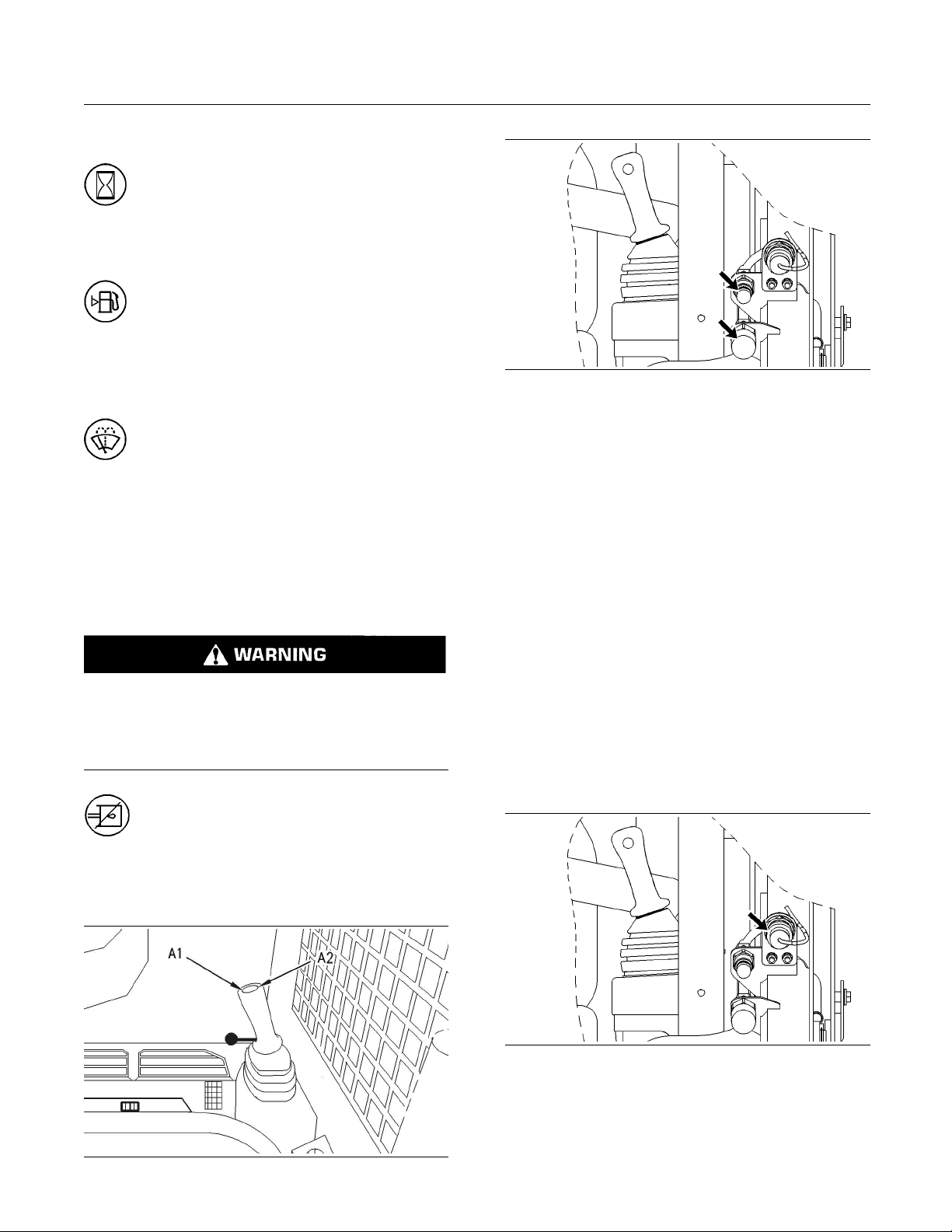
SEBU7494-06 61
Operation Section
Machine Operation
Service Hour Meter (19)
Service Hour Meter – The service hour
meter should be used to determine service
hour maintenance intervals.
Fuel Level Gauge (20)
Fuel Level Gauge – Theneedleinthe
yellow range indicates low fuel.
Window Wiper and Window Washer
(21)
Window Wiper and Window Washer (If
Equipped) – Movetheswitchtothemiddle
position in order to turn on the wiper. Press
on the right side of the switch in order to operate the
washer. Press on the left side of the switch in order
to turn off the wipers.
Hydraulic Shutoff Control (22)
Note: Activate the hydraulic shutoff control when you
are roading the machine.
Personal injury or death can result from the work
tool falling.
Fully lower the loader arms before you release the
hydraulic system pressure.
Hydraulic Shutoff Control – Press on
the bottom of the switch in order to disable
the hydraulic functions. Press the top of the
switch in order to activate the hydraulic functions.
Illustration 41
Note: Simple hydromechanical work tools may be
shipped without hydraulic oil. Uneven movement
may occur until all the air has been removed from the
work tool. You may need to add hydraulic oil to the
machine after the machine fills the circuits of the work
tool. Refer to Operation and Maintenance Manual,
“Hydraulic System Oil Level - Check” for the proper
procedure for checking the hydraulic oil level.
Auxiliary Hydraulic Control – Press the left side of
the auxiliary hydraulic control (A1) in order to provide
hydraulic oil flow to the lower auxiliary hydraulic
line. Press the right side of the auxiliary hydraulic
control (A2) in order to provide hydraulic oil flow to
the upper auxiliary hydraulic line. The machine may
be equipped with a auxiliary hydraulic control that is
proportional. On machines that are equipped with
a proportional control, hydraulic flow will vary with
the amount of pressure that is applied to auxiliary
hydraulic control.
g00902862
Auxiliary Electrical Control (24)
Auxiliary Hydraulic Control (23)
Illustration 40
g0090285
Illustration 42
3
g00897773
Page 62

62 SEBU7494-06
Operation Section
Machine Operation
Auxiliary Electrical Control (If
Equipped) – The auxiliary electrical control
supplies cont
electrical harness that is located on the loader arm.
Press on the bottom of the switch in order to turn on
electrical p
order to turn off electrical power.
ower. Press on the top of the switch in
inuous electrical power to the
Plugged (25)
This space is not used on the machine. This space
may be used fo
Automatic Le
loader lift arms are raised. Press on the bottom of the
switch in or
Press on the top of the switch in order to deactivate
the automatic level control.
r future functions.
vel Control (26)
Automatic Level Control (If Equipped) –
The Automati
the selected angle of the work tool as the
der to activate the automatic level control.
c Level Control maintains
Continuous Flow and Interlock
Override (
27)
Interlock Override (If Equipped) – The
interlock override function allows the
auxiliary hyd
the armrest in the RAISED position. First activate the
continuous flow function. If the machine is equipped
with a single
the switch in order to activate the interlock override. If
the machine is equipped with a dual function switch
then press t
the interlock override function. In order to turn off
the interlock override function and continuous flow
function, p
switch or Interlock Override switch.
Do not leave the machine unattended while you have
the interlock override function activated.
function switch then press the bottom of
he top of the switch in order to activate
ress either side of the auxiliary hydraulic
raulic circuits to function with
NOTICE
Rear Auxiliary Hydraulic Control or
Fourth Function Control (28)
Machines that are equipped with Continuous Flow
and Interl
on one switch. Your machine may be equipped with
a switch that only supports the Interlock Override
function.
hydraulic circuit without continuously holding the
auxiliar
auxiliary hydraulic control. Press on the bottom of the
continuous flow switch and release the continuous
flow swi
hydraulic control after you release the continuous
flow switch. The continuous flow function will not be
activat
hydraulic control within one second of releasing the
continuous flow switch. Press on either the auxiliary
hydrau
order to stop the flow to the auxiliary circuit.
ock Override will support both functions
Continuous Flow (If Equipped) – The
continuo
flow of hydraulic fluid to the auxiliary
y hydraulic control. Press on either side of the
tch. Immediately release the auxiliary
ed if the operator does not release the auxiliary
lic control or the continuous flow switch in
us flow control supplies continuous
Illustration 43
Illustration 44
g00902830
g009028
34
Page 63
SEBU7494-06 63
Operation Section
Machine Operation
Fourth Functio
fourth function control provides electrical power in
order to control a three-position diverter valve that is
located on som
the switch (C1) in order to send power to the pin (A).
Press the left side of the switch (C2) in order to send
power to pin (
Rear Auxiliary Hydraulic Control (If Equipped) –
In order to ac
activate the continuous flow function for the front
auxiliary hydraulics. Press the left side of the switch
in order to d
Press the right side of the switch in order to direct
flow to the upper rear hydraulic line.
n Control (If Equipped) – The
e work tools. Press the right side of
B).
tivate the rear auxiliary hydraulics,
irect flow to the lower rear hydraulic line.
Temperature Control (29)
Te mperature Control (If Equipped)
Suspension
Suspension Seat (If Equipped)
Seat (30)
Basic Operation
MSS may be programmed to read a standard
Caterpillar key or an electronic key. The electronic
key contains an electronic chip within the plastic
housing for the key. Each key emits a unique
signal to the MSS. The keys can be identified by a
gray housing or a yellow housing. MSS can have
programmed settings to require an electronic key or
a standard Caterpillar key for starting during certain
periods of time.
When the key start switch of the machine is turned
to the ON position, the ECM will read the unique ID
that is stored in the electronic key. The ECM will
then compare this ID to the list of authorized keys.
The following table tells the operator the status for
starting the machine. The status light is located near
the key start switch.
Table 12
Green light
Red light The key is not authorized.
Note: MSS will not shut down the machine after the
machine has started.
The machine will start.
Fan Speed Con trol (31)
Fan S peed Co
ntrol
Air Conditioner Control (32)
Air Conditioner Control (If Equipped)
Machine Sec
urity System (If
Equipped)
NOTICE
This machine is equipped with a Caterpillar Machine
Security System (MSS) and may not start under certain condit
know your machine’s settings. Your Caterpillar Dealer
can identify your machine settings.
can be identified by a decal in the operator station.
MSS is designed to prevent theft of the machine or
unauthori
ions. Read the following information and
Machine Security System (MSS) –
Machines that are equipped with a
Caterpill
zed operation.
ar Machine Security System (MSS)
Security Management
The MSS has the capability to allow you to program
the system to automatically activate at different time
periods with different keys. The MSS can also be
programmed to reject a specific electronic key after a
selected date and time. When you turn the key to the
OFFpositionandtheMSSisactive,youhavea30
second interval in order to restart the machine with
an unauthorized key. Also if the machine stalls, there
is a 30 second interval for restarting the machine.
This 30 second interval is counted from the time of
turning the key to the OFF position.
Note: Know your machine’s settings because the use
of an electronic key is no guarantee that the machine
canberestarted.
An expiration date can be set for each electronic key
that is contained in the list of keys for the machine.
The key will no longer start the machine when the
internal clock in the security system passes the
expiration date. Each entry in the list of keys can
have a different expiration date.
Spare keys are available from your dealer. Before a
key can operate the machine, the MSS must be set
to accept that particular key. Contact your Caterpillar
dealer for information on additional features of the
MSS.
Page 64

64 SEBU7494-06
Operation Section
Machine Operation
i01635456
Seat and Armrest (5) – The alert indicator
Alert Indicators
SMCS Code: 7450; 7451
the operator gets out of the operator seat. The alert
will light when the armrest is in the RAISED
position. The
alert indicator will light when
indicator should go out when the operator is in the
operator sea
t and the armrest is in the LOWERED
position.
Parking Brake (6) – The alert indicator will
light when th
e parking brake is engaged.
The alert indicator should come on during
start-up. The alert indicator should go out when the
parking bra
ke is disengaged.
Charging System (7) – The alert indicator
will light if there is a malfunction in the
electrical
system. If this alert indicator
comes on, the system voltage is too high for normal
machine operation or too low for normal machine
operation.
Illustration 45
g00846559
Hydraulic Oil Temperature (1) – The
alert indicator will light and an audible alert
will sound when the temperature of the
hydraulic oil is too high. If this indicator comes on,
stop the machine immediately. Stop the engine and
investigate the problem.
Engine Coolant (2) – The alert indicator
will light and an audible alert will sound
when the engine coolant temperature is too
high. If this alert indicator comes on, stop the machine
immediately. Stop the engine and investigate the
cause.
Engine Oil Pressure (3) – The alert
indicator will light and an audible alert will
sound when the engine oil pressure is low.
If this alert indicator comes on, stop the machine
immediately. Stop the engine and investigate the
cause.
If electrical loads are high and the engine speed is
near low idle, increase the engine speed to high idle.
This will ge
nerate more output from the alternator. If
the alert indicator for the electrical system turns off
within one minute, the electrical system is probably
operating
in a normal manner. However, the electrical
system may be overloaded during periods of low
engine speeds.
Increase the engine idle speed with the governor
lever in order to compensate for a higher electrical
load on th
esystem.
If this procedure does not cause the alert indicator to
turn off,
move to a convenient location. Investigate
the cause (loose alternator belt, broken alternator
belt, faulty batteries, etc).
Rabbit Mode (8) (If Equipped) – The
alert indicator will light when rabbit mode is
selecte
d with the two-speed control.
Hydraulic Oil Filter (4) – The indicator
will light when the hydraulic oil filter is not
functioning properly. Stop the machine and
replace the oil filter. The indicator will stay on until
the hydraulic oil has warmed up. Do not operate the
machine until the light turns off.
Page 65
SEBU7494-06 65
Operation Section
Engine Starting
Engine Starting
i02404494
Engine Starting
SMCS Code: 1000; 7000
Do not use aerosol types of starting aids such as
ether. Such use could result in an explosion and
personal injury.
It is important to prepare the machine for operation
in temperatures that are below 0 °C (32 °F). It
is also important to follow the appropriate warm
up procedures when the machine is operated in
temperatures that are below 0 °C (32 °F).
Machine preparation for cold weather includes
using the correct hydraulic system oil. The factory
fills the hydraulic system with 10W hydraulic oil
which has a minimum operating temperature of
−20 °C (−4 °F). If the machine will be operated at
temperatures below −20 °C (−4 °F), the 10W oil
must be replaced with 0W30 hydraulic oil in order to
provide the proper oil viscosity. Refer to Operation
and Maintenance Manual, “Lubricant Viscosities
and Refill Capacities”. Refer to Operation and
Maintenance Manual, SEBU5898, “Cold Weather
Recommendations for Caterpillar Machines”. Refer
to Operation and Maintenance Manual, SEBU6250,
“Caterpillar Machine Fluids Recommendations”.
NOTICE
Keep the engine speed low until the engine oil pressure ale
not go out within ten seconds, stop the engine and investigate the cause before starting again. Failure to
do so can
rt indicator goes out. If the alert indicator does
cause engine damage.
3. Move the govern
pedal to half throttle.
4. Turn the engin
position in order to start the engine. Release the
key after the engine has started.
Note: If you are starting the engine below 0 °C
(32 °F), turn the engine start switch key to the ON
position and
switch for ten seconds and then turn the key to the
START position. After the engine starts, continue
to press the g
smoothly.
Do not operat
onds at one time. Damage to the glow plugs could occur.
5. Disengage t
6. Run the engine for 5 minutes before performing
the followi
throttle. Hold the work tool control in the TILT
BACK position for thirty seconds. Release the
control for
control in the LOWER position for thirty seconds.
Release the control for thirty seconds. Perform
the proced
Note: If you are operating the machine below 0 °C
(32 °F), pe
Do not use the hydraulic interlock override function to
warm up the
7. Keep all personnel away from the machine. Move
the machine very slowly to an open area. Repeat
Step 6 as you move the machine back and forth
for 3 m (10 ft).
press the glow plug switch. Hold the
rform the procedure for eight minutes.
or control lever or the accelerator
e start switch key to the START
low plug switch until the engine runs
NOTICE
e the glow plugs for more than 30 sec-
he parking brake.
ng procedure. Run the engine at half
thirty seconds. Hold the work tool
ure for three minutes.
NOTICE
machine.
NOTICE
If the engine does not start within fifteen seconds, disengage the starter. Release the glow plug switch if it is
being used. Wait for ten seconds and repeat the procedure.
NOTICE
If you fa
to the engine or damage to the hydraulic system may
occur.
1. Fasten t
2. Pull the armrest downward.
il to follow the steps described below, damage
he seat belt.
Note: More warm up time may be required if the
hydraulic functions are sluggish.
Page 66
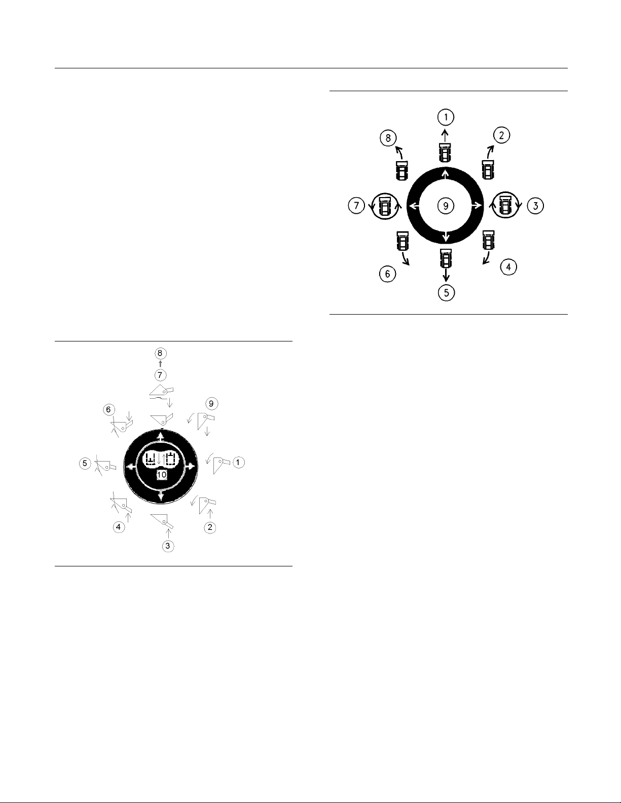
66 SEBU7494-06
Operation Section
Operation
Operation
i02121219
Operation Information
SMCS Code: 7000
General Information
1. Adjust the operator’s seat.
2. Fasten the seat belt.
3. Lower the armrest.
4. Start the engine and allow the machine to warm
up. Refer to Operation and Maintenance Manual,
“Engine Starting”.
5. Disengage the parking brake.
Illustration 46
(1) TILT FORWARD
(2) TILT FORWARD AND RAISE
(3) RAISE
(4) T ILT BACK AND RAISE
(5) TILT BACK
(6) TILT BACK AND LOWER
(7) LOWER
(8) FLOAT
(9) TILT FORWARD AND LOWER
(10) HOLD
g01080546
6. Raise all lowered work tools and attachments in
order to negotiate any obstacles.
Illustration 47
(1) FORWARD
(2) RIG HT TURN
(3) RIGHT S POT TURN
(4) REVERSE LEFT TURN
(5) REVERSE
(6) REVERSE RIGHT TURN
(7)LEFTSPOTTURN
(8) LE FT TURN
(9) HOLD
g00741590
7. Smoothly move the speed and direction control for
the desired direction and speed.
To prevent injury, make sure that no people are
workingonthemachineornearthemachine.To
prevent injury, keep the machine under control at all
times.
Do not allow the machine to overspeed when you
go downhill. Move the speed/direction control lever
toward the HOLD position in order to reduce th e
speed of the machine when you are going downhill.
For additional information, refer to Operation and
Maintenance Manual, “Operating on a Slope”.
Always put the heaviest end of the machine uphill
whenyouareworkingonanincline.
The loader arms of the machine should be fully
lowered onto the stops when you are digging with the
machine. Digging with the loader arms in the fully
lowered position will transfer the stress that is placed
on the loader arm into the frame.
Page 67

SEBU7494-06 67
Operation Section
Operation
NOTICE
The use of this m
achine in certain applications can
cause premature failure of the rubber tracks and rubber wheels. Applications that may cause premature
failure of the
rubber tracks and rubber wheels include:
useinrockyterrain,useingravel,useinconcretedemolition, use in terrain where metal debris is present,
and any appli
cation that would require a solid tire on
a skid steer loader. Damage to the rubber tracks and
rubber wheels that is caused from using the machine
in these cond
itions is not covered under warranty.
Avoid any situation that causes the tracks of the
machinetosp
in on the ground. Avoid spinning the
tracks. This will extend the life of the track.
Operating on a Slope
Never excee
d a slope that is greater than 3 to 1
(18.4°).
When it is po
ssible, avoid operating the machine
across a slope. When it is possible, operate the
machine up a slope and down a slope. Do not turn
the machin
e while you are operating on a slope.
NOTICE
When it is necessary to operate the machine on a
slope, keep
bucket loads light in order to decrease the
possibility of derailing the tracks.
NOTICE
If the correct method for turning is not followed, the
tracks may derail.
When it is necessary to travel across a slope, the
following steps should always be followed:
Illustration 48
1. Stop the m
achine. Turn the machine slowly while
g00802153
you are backing down the slope.
Note: Do n
ot back up a hill in order to turn.
2. Position the machine so that the front of the
machine f
aces the direction for travel that is
desired.
Page 68
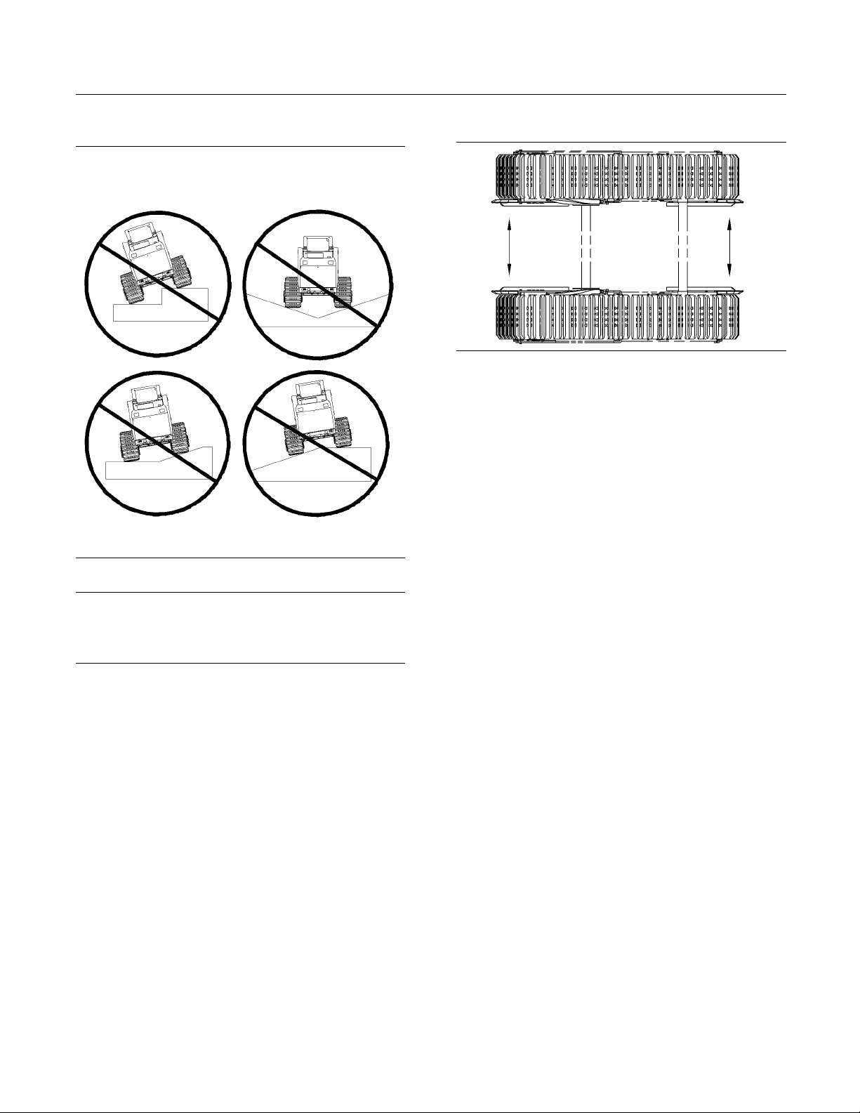
68 SEBU7494-06
Operation Section
Operation
Operating on a Transition
Track Guides
Illustratio
n50
Track Guides are available for the 267 and 277
machines on
ly. The use of track guides on the 267
and 277 machines will minimize the risk of derailing
the tracks on a transition or a slope. Track guides
should not b
eusedasasubstituteforproper
machine operation. Even if track guides are
installed, the machine should not be operated on
slopes tha
t are greater than 3 to 1 (18.4°)..
g00929633
Illustration 49
g00803882
NOTICE
Avoid operating this machine on transitions. Operating
this mach
ine on transitions may cause the tracks to
derail.
When the machine is operated on a transition, the
tracks ma
y not be supported fully.
When the tracks are not supported fully, the wheels
may ride o
n top of the drive lugs of the tracks.
The track will derail if you continue to travel on the
transition.
If you must travel on a transition, travel the machine
at 90° to the transition. Do not perform hard turns or
fast tur
ns when you are operating the machine on
the transition.
Track guides are installed on the undercarriage
frame. The
track guides work in the following manner.
When a track starts to derail the track will contact the
guide. The track will start to climb on top of the guide.
If the ope
rator continues to run the machine in the
same direction, the drive motor for the track will stall.
At this point, the operator can reverse the direction of
the machi
ne and the track will go back into position.
The life of the tracks and the bogies will be reduced
if the tr
acks are derailed against the track guides.
Any wear or damage to the tracks, the bogies or
the undercarriage components that is caused by
ng the tracks is not warrantable.
deraili
Track guides will wear with use. Track guides that are
worn may
damage the tracks. Damage to the tracks
that results from worn track guides is not warrantable.
Replace the track guides as it is necessary.
Contact your local Caterpillar dealer for the correct
installation procedure. Refer to Special Instruction,
REHS11
99, “Installation Procedure for the Multi
Terrain Loader Track Guide”.
Page 69
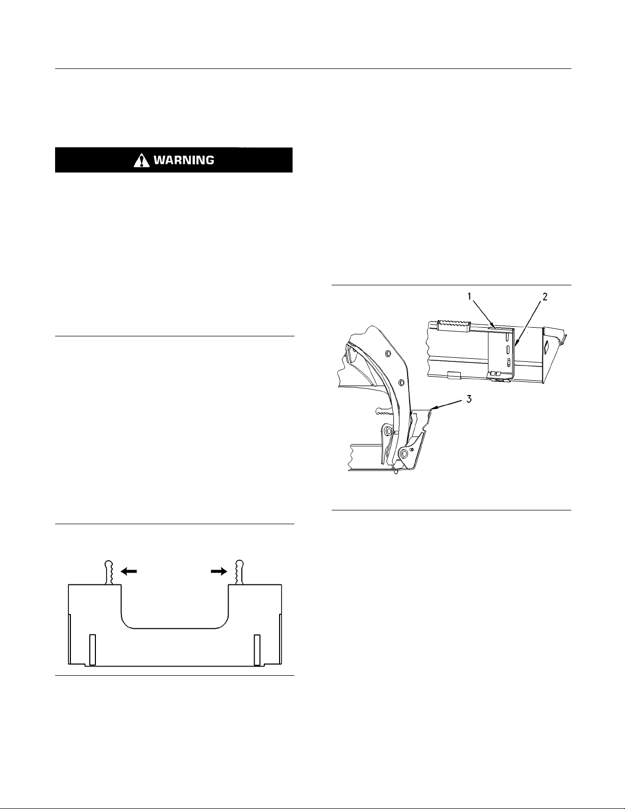
SEBU7494-06 69
Operation Section
Operation
i01935351
Work Tool Coupler Operation
SMCS Code: 6129; 7000
Improper attachment of work tools could result in
injury or death.
Do not operate this machine until you have positive indication that the coupler pins are fully engaged. Check for engagement by:
1. Tilt the work tool down.
2. Put down pressure on the work tool.
3. Back the machine up and make sure there is
not any movement between the work tool and the
quick coupler assembly.
Attaching the Work Tool
Note: Before you install the work tool, inspect the
coupler and the work tool mounting bracket for any
wear or for any damage. Refer to Operation and
Maintenance Manual, “Quick Coupler Assembly Inspect” and Operation and Maintenance Manual,
“Work Tool Mounting Bracket - Inspect” for inspection
procedures.
2. If the machine i
s equipped with a manual coupler,
ensure that the levers for the coupler are in
the DISENGAGED position. If the machine is
equipped with
a hydraulic quick coupler refer to
Operation and Maintenance Manual, “Work Tool
Coupler Operation” for details on disengaging the
coupler pins
.
3. Enter the machine.
4. Fasten the seat belt and lower the armrest.
5. Start the eng
ine.
6. Disengage the parking brake.
7. Tilt the quick coupler assembly forward.
1. Position the work tool on a level surface. Move the
hydraulic lines (if equipped) for the work tool and
electrical lines (if equipped) away from the work
tool mounting bracket.
Illustration 51
g009297
Illustration 52
g00929878
8. Align the quick coupler assembly (3) between the
outer plates (2) of the mounting bracket. Move the
quick coupler assembly under the angled plate (1)
of the mounting bracket and rack back the work
tool.
9. Fully lower the loader arms.
10. Tilt the work tool forward until the work tool is
slightly off the ground.
11. Turn the engine start switch key to the OFF
76
position in order to stop the engine.
12. If the work tool requires hydraulics, refer to
the section “Releasing the Hydraulic System
Pressure”.
13. Exit the machine.
Page 70
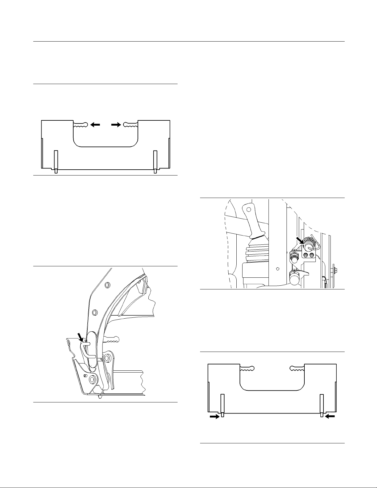
70 SEBU7494-06
Operation Section
Operation
Note: If you are
installing a material handling arm
that is not equipped with the optional center step,
do not exit the machine. A second person needs to
perform steps
Illustration 53
14 through step 16.
g00929831
14. If the machine is equipped with a manual coupler,
ensure that the levers for the coupler are in the
ENGAGED position. If the machine is equipped
with a hydraulic quick coupler refer to Operation
and Maintenance Manual, “Work Tool Coupler
Operation” for details on engaging the coupler
pins.
a. Route the hydra
ulic hoses through the hose
guide on the machine in order to prevent
damage to the hoses. Not all work tools require
the hydraulic
hoses to be routed through the
hose guide. The work tool Owner’s Manual will
inform you if the hydraulic hoses need to be
routed throu
gh the hose guide. The Caterpillar
simple hydromechanical work tools require the
hoses to be routed through the hose guide.
b. Ensure that the quick connect couplers are
clean.
c. Connect the auxiliary hydraulic hoses for the
work tool to the machine. Twist the collar of the
quick conne
ct coupler for one quarter of a turn
in order to secure the hydraulic connections.
d. If the work t
ool is equipped with electrical lines,
then route the electrical lines with the hydraulic
hoses.
15. If the work tool requires hydraulics, then use the
following procedure.
Illustration 54
g00929874
Illustration 55
e. Connect the wire harness (if equipped) to the
electrical connector on the machine.
f. Connect the water line (if equipped) to the
electrical connector for the water line on the
machine.
g00897773
Illustration 56
g00929897
Page 71

SEBU7494-06 71
Operation Section
Operation
16. Visually ensur
extending out of the holes in the work tool
mounting bracket.
17. Use the following procedure to verify engagement
of the coupler pins.
a. Enter the machine.
b. Fasten the sea
c. Start the engine.
d. Disengage the parking brake.
e. Keep the work t
f. Activate the tilt control in order to tilt the work
tool downward
g. Apply down pressure on the work tool.
Note: The work tool Owner’s Manual will inform you
if forward pressure should not be applied on a work
tool.
h. Move the machine backward. Ensure that there
is no movemen
quick coupler assembly.
18. Te st t h e w o r k
operation.
e that both coupler pins are
t belt and lower the armrest.
ool close to the ground.
.
t between the work tool and the
tool for leaks and for proper
Removing the Work Tool
3. Rack back the wo
slightly off the ground.
4. Turn the engin
position in order to stop the engine.
5. If the work too
the section “Releasing the Hydraulic System
Pressure”.
6. Perform Step 7 through Step 12 only after you
have released the hydraulic system pressure.
7. Disconnect the auxiliary hydraulic hoses from the
machine.
Note: If protective caps are available, install
protective caps over the quick connect couplers.
8. If hoses are routed through the hose guide,
remove the hoses from the hose guide. Move the
hoses to a po
mounting bracket.
Note: Conne
Connecting the hoses together will reduce the
probability of contaminating the hydraulic system.
Connecting
buildup of pressure in the hoses. Connecting the
hoses together will ease the connection of the hoses
to the mach
9. Iftheworktoolisequippedwithanelectrical
line, then
connector on the machine. If protective caps are
available, install protective caps over the electrical
connecto
ct the hoses for the work tool together.
the hoses together will reduce the
ine.
disconnect the wire harness from the
rs.
rk tool until the work tool is
e start switch key to the OFF
l requires hydraulics, refer to
sition that is away from the work tool
Disengaging the coupler pins will release the work
tool from c
Serious injury or death may result from disengaging the wor
or carrying a load.
Place the w
engaging the coupler pins.
Auxiliary hoses for work tools must be disconnected
before the quick coupler is disengaged.
Pulling the work tool with the auxiliary hoses could
result in damage to the host machine or the work tool.
1. Position the machine on level ground.
2. Lower the work tool to the ground.
ontrol of the operator.
k tool when it is in an unstable position
ork tool in a safe position before dis-
NOTICE
10. If the auxiliary electrical line is routed through the
hose guid
Move the auxiliary electrical line to a position that
is away from the work tool mounting bracket.
11. If the work tool is equipped with a water line, then
disconnect the water line from the connector on
the mach
is away from the work tool mounting bracket.
12. Exit the
Note: If you are removing a material handling arm
that is n
do not exit the machine. A second person needs to
perform step 13.
e, remove the line from the hose guide.
ine. Move the water line to a position that
machine.
ot equipped with an optional center step,
Page 72
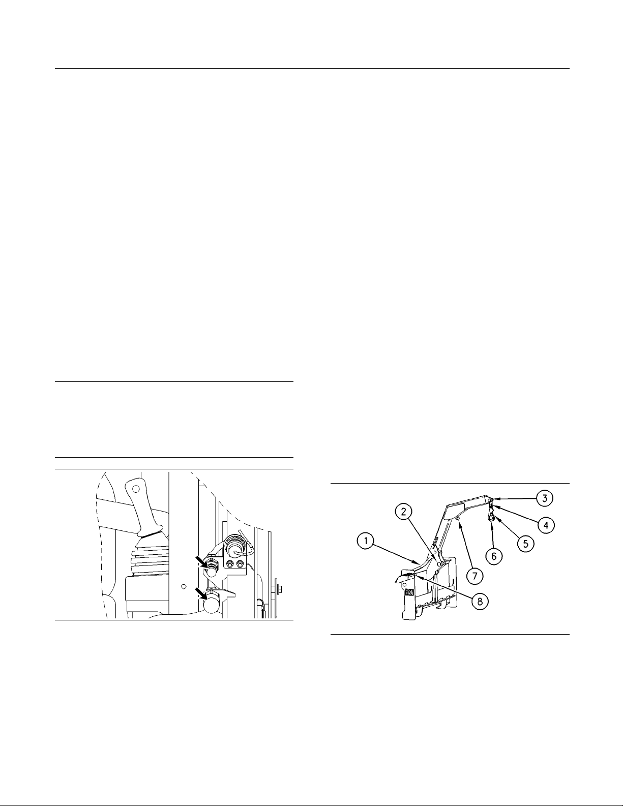
72 SEBU7494-06
Operation Section
Operation
13. If the machine i
s equipped with a manual coupler,
ensure that the levers for the coupler are in
the DISENGAGED position. If the machine is
equipped with
a hydraulic quick coupler refer to
Operation and Maintenance Manual, “Work Tool
Coupler Operation” for details on disengaging the
coupler pins
.
14. Enter the machine.
15. Fasten the seat belt and lower the armrest.
16. Start the eng
ine.
17. Disengage the parking brake.
18. As you slowly back away from the mounting
bracket, tilt the quick coupler assembly forward
until the top
of the quick coupler assembly clears
the angled plate.
19. Back away fr
Releasing t
om the work tool.
he Hydraulic System
Pressure
NOTICE
If the work tool is equipped with an Owner’s Manual,
follow the p
Manual for that work tool. Damage to the work tool and
the machine may occur if you do not follow the proper
installati
rocedure that is described in the Owner’s
on procedure.
3. Press each side
of the auxiliary hydraulic control
switch (A1 and A2) for one to two seconds in order
to release the auxiliary system pressure. Keep the
joystick cont
rol in the NEUTRAL position while
you press the auxiliary hydraulic control switch
(A1 and A2).
4. Engage the parking brake.
5. Start the eng
ine and run the engine for at least 15
seconds in order to recharge the accumulator.
6. Stop the engi
ne.
7. Immediately turn the engine start switch key to the
ON position.
Disengage the parking brake.
8. Move both of the joystick controls through all of
the operatin
g positions in order to release the
hydraulic pressure in the work tool system and
the hydrostatic system.
9. Turn the engine start switch key to the OFF
position.
The pressure in the hydraulic system has now
been released.
i01964204
Material Handling Arm
Operation
Illustration 57
Auxiliary quick connectors
g00902862
1. Turn the engine start switch to the OFF position.
Do n ot raise the armrest.
2. Immediately turn the engine start switch key to the
ON position. Do not start the engine. Disengage
the parking brake.
SMCS Code: 6400; 6700; 7000
tion 58
Illustra
(1) Location of Optional Center Step
(2) Tie-Down Poin t
(3) Lifting Point 2
(4) Shackle
(5) Hook Clasp
(6) Hook
(7) Lifting Point 1
(8) Stored location of Position Lock Pin
g00674640
Page 73

SEBU7494-06 73
Operation Section
Operation
Inspect the mat
erial handling arm and the
attachments for wear and damage. Ensure that the
load is properly attached to the material handling arm
before you ope
rate the machine.
Note: The physical size and the weight of the load
determines t
he lifting point that is appropriate.
Whenever it is possible, use the lifting point 1. This
will improve the stability and this will reduce the
movement of t
he load. Refer to the Operation and
Maintenance Manual, “Material Handling Arm Rated
Load” for the limitations on the weight.
Note: Use only Caterpillar 9V-2714 Hook and
Caterpillar 9V-2715 Shackletoattachaloadtothe
material ha
ndling arm. Never use an open hook. Use
a line that is rated for 2.5 times the weight of the load.
Do not allow anyone to be near a s uspended load
unless the
position lock pin is installed. If the lift
arms must be raised to handle a tall load, do not
allow anyone to be near the suspended load unless the li
ft arms are blocked. Failure to follow the
instructions or heed the warnings could result in
injury or death.
5. Keep the loader
arms in the fully lowered position.
Slowly position the material handling arm until
either lifting point 1 or the lifting point 2 is directly
above the load
.
6. Tilt the material handling arm forward until the
hook is sligh
tly higher than the load in order to
minimize swinging of the load.
7. Stop the engi
ne.
8. Wait as the second person attaches the load
securely to t
he hook. The second person needs
to ensure that the hook clasp is in the locked
position.
9. Ensure that ALL personnel have left the work area.
10. Start the eng
ine.
11. Disengage the parking brake.
12. Slowly tilt back the material handling arm until the
material handling arm is fully tilted back.
13. Stop the engine.
Two Person Operation
Attaching A Load
1. Verify tha
limit. Refer to the Operation and Maintenance
Manual, “Material Handling Arm Rated Load” for
the rated
2. Keep all personnel out of the work area at all
times, ex
a load.
3. Enter th
4. Disengage the parking brake.
t the load does not exceed the weight
load capacities.
cept when you are attaching or removing
e machine. Start the engine.
Illustration 60
g01020535
14. Wait as the second person installs the position
lock pin through the hole in the material handling
arm and the hole in the loader arm of the machine.
Note: This will prevent the material handling arm
from tilting forward.
Illustration 59
15. Wait as the second person secures the load to
the tie-down points with a suitable line in order
to minimize load swing.
g01020534
Page 74
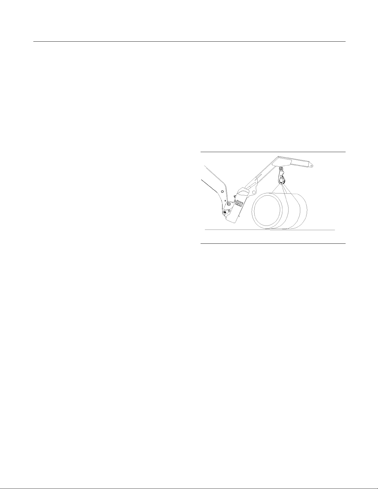
74 SEBU7494-06
Operation Section
Operation
Note: Do not mov
the load. Do not pull the load toward the material
handling arm when you are securing the load to the
tie-down poin
16. Wait as the second person removes the position
lock pin. Wai
in the STORED position on the material handling
arm.
e the load when you are securing
ts.
t as the second person places the pin
Removing a Load
1. Slowly tilt b
material handling arm is fully tilted back. Lower
the loader arms fully.
2. Stop the engine.
3. Wait as the se
lock pin through the hole in the material handling
arm and the hole in the loader arm of the machine.
4. Wait as the second person removes the line that
secures the load to the tie-down points.
5. Wait as the second person removes the position
lock pin. Wait as the second person places the pin
in the STORE
arm.
6. Remove all
7. Start the engine.
8. Disengage the parking brake.
ack the material handling arm until the
cond person installs the position
D position on the material handling
personnel from the work area.
Attaching the L
1. Verify that the load does not exceed the weight
limit. Refer t
Manual, “Material Handling Arm Rated Load” for
the rated load capacities.
2. Keep all personnel out of the work area at all
times, except when you are attaching or removing
a load.
3. Enter the machine. Start the engine.
4. Disengage the parking brake.
Illustration 61
5. Keep the loader arms in the fully lowered position.
Slowly position the material handling arm until
either lifting point 1 or lifting point 2 is directly
above the load.
oad
o the Operation and Maintenance
g01020534
9. Lower the l
10. Stop the engine.
11. Wait as the second person removes the load from
the hook.
12. Remove all personnel from the work area.
13. Start the e
14. Disengage the parking brake.
15. Slowly tilt back the material handling arm until the
material handling arm is fully tilted back.
16. Back away from the load.
oad to the ground.
ngine.
One Person Operation
Note: The m
with a center step in order to do the one person
operation.
aterial handling arm must be equipped
6. Tilt the material handling arm forward until the
hook is slightly higher than the load in order to
minimize swinging of the load.
7. Stop the engine. Exit the machine.
8. Attach the load securely to the hook. Ensure that
the hook clasp is in the LOCKED position.
9. Keep all personnel out of the work area.
10. Enter the machine. Start the engine.
11. Disengage the parking brake.
12. Slowly tilt back the material handling arm until the
material handling arm is fully tilted back.
13. Stop the engine. Exit the machine.
Page 75
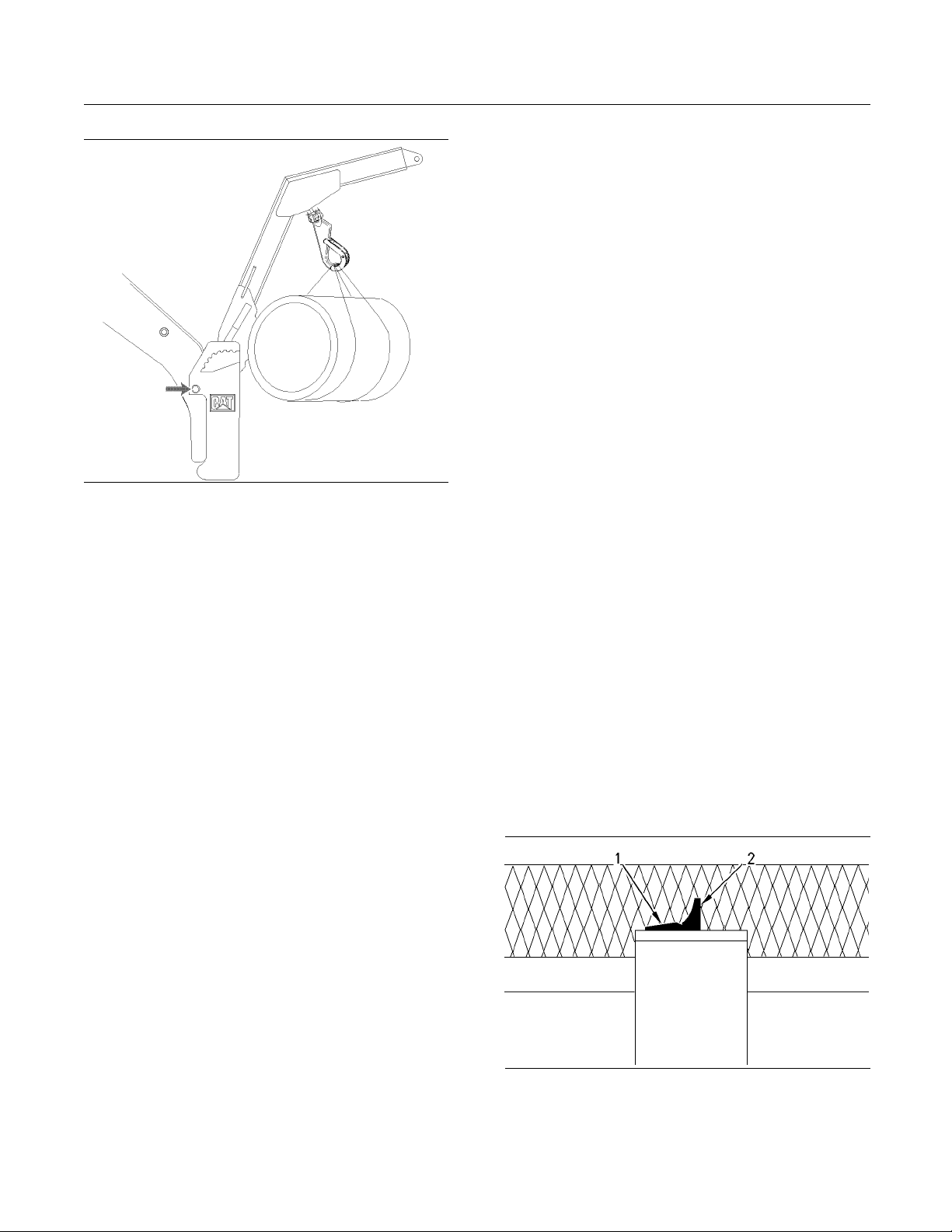
SEBU7494-06 75
Operation Section
Operation
Illustration 62
g01020535
14. Install the position lock pin through the hole in the
material handling arm and the hole in the loader
arm of the machine.
9. Lower the load t
o the ground.
10. Stop the engine. Exit the machine.
Note: Make sure that the load is stable.
11. Remove the loa
d from the hook.
12. Keep all personnel out of the work area.
13. Enter the machine. Start the engine.
14. Disengage the
parking brake.
15. Slowly tilt back the material handling arm until the
material hand
ling arm is fully tilted back.
16. Back away from the load.
TravelingwithaLoad
1. Ensure that al
2. Start the engine.
3. Disengage the parking brake.
l personnel have left the work area.
15. Secure the load to the tie-down points with a
suitable line in order to minimize load swing.
Note: Do not move the load when you are securing
the load. Do not pull the load toward the material
handling arm when you are securing the load to the
tie-down points.
16. Remove the position lock pin and place the pin in
the STORED position on the material handling
arm.
Removing a Load
1. Fully tilt back the material handling arm. Fully
lower the loader arms.
2. Stop the engine. Exit the machine.
3. Install the position lock pin through the hole in the
loader arm of the machine.
4. Remove the line that secures the load to the
tie-down points .
5. Remove the position lock pin and place the pin in
the STORED position on the material handling
arm.
6. Keep all personnel out of the work area.
7. Enter the machine. Start the engine.
4. Raise the load
so that the load is slightly off of the
ground.
5. Slowly travel
to the destination. Keep the load as
close to the ground as possible. Travel up slopes
with the load uphill. Travel down slopes with the
load uphill.
Do not travel across slopes.
i01878348
Pallet Forks Operation
SMCS Code: 6700; 7000
Illustration 63
The “type 1” pin that is in the unlocked pos ition (2) and the locked
position ( 1).
g0095593
7
8. Disengage the parking brake.
Page 76

76 SEBU7494-06
Operation Section
Operation
Illustration 64
The “type 2” pin that is in the unlocked position (1) and the locked
position (2).
g00955964
1. Put the fork tines in the Unlocked position. Space
the fork tines as far as possible from each other.
2. Put the fork tines in the Locked position.
3. Slowly, move the machine into position and
engage the load. The machine should be square
with the load. Space the forks evenly between the
pallet stringers.
While you opera
te the machine and the work tool
slowly in an open area, check for proper operation of
all controls and all protective devices on the machine
and the work to
Illustration 65
joystick for the fourth function control (C1 and C2) and joystick for
the auxiliary hydraulic control (A1 and A2)
ol.
g00793391
Note: For standard flow machines, use the A2
function in order to supply hydraulic oil flow to the
work tools that require continuous flow.
4. Move the machine forward until the load contacts
the carriage.
5. Lift the load carefully.
6. Slowly, move the machine in reverse until the load
is clear enough to lower.
7. Carefully lower the load while you tilt the forks
back to the travel position.
Travel with the load as low as possible while you still
maintain ground clearance.
Travel with the load uphill on upgrades and on
downgrades.
i01871947
Work Tool Operation
SMCS Code
The following tables describe the functionality of the
Auxiliar
the Fourth Function Control when you operate the
machine with approved Caterpillar hydromechanical
work tool
: 6700; 7000
y Hydraulic Control and the functionality of
s.
Page 77

SEBU7494-06 77
Operation Section
Operation
Table 13
OPERATION OF CATERPILLAR SIMPLE HYDROMECHANICAL WORK TOOLS
Work Tool
Multipurpose Bucket
Bucket and Utility
Grapple Bucket
Angle Blade N/A
(1)
The control is not applicab le.
Table 14
OPERATION OF CATERPILLAR COMPLEX HYDROMECHANICAL WORK TOOLS
Work Tool
A13 Auger and
A19 Auger
BA18 Angle
Broom
BP15Pickup
Broom and
BP18 Pickup
Broom
CV16 Vibratory
Compactor and
CV18 Vibratory
Compactor
Landscape
Rake and LR18
Landscape
Rake
LT13 and LT18
Landscape
Tiller
Position
of Fourth
Function
Control
C2 C1 A1 A2
(1)
N/A
N/A
Position
Position of
of Fourth
Function
Control
C2 C1 A1 A2
(1)
N/A
X The auger bit rotates counterclockwise when you view the auger from
X
X
N/A
N/A
N/A
N/A
Position of
Auxiliary
Hydraulic
Control
Results
X The bucket will close.
X The bucket will open.
X The grapple will close.Industrial Grapple
X The grapple will open.
X The blade will angle to the left.
X The blade will angle to the right.
Auxiliary
Hydraulic
Control
X
The auger bit rotates clockwise when you view the auger from the motor
Results
end.
the motor end.
X
The broom rotates clockwise when you view the left side of the broom.
X The broom head articulates to the left while the broom rotates. This
operation is not applicable to an angle broom with manual angling.
X The broom head articulates to the right while the broom rotates. This
operation is not applicable to an angle broom with manual angling.
The broom rotates clockwise when you view the left side of the broom.
X
X The eccentric shaft rotates counterclockwise when you view the left side
of the vibratory compactor.
X
The eccentric shaft rotates clockwise when you view the left side of the
vibratory compactor.
X The rake cover opens.LR15
X
The conveyor rotates counterclockwise when you view the left side of the
landscape rake. If the rake cover is open, the rake cover will close.
X The tiller drum rotates clockwise when you view the left side of the
landscape tiller.
X
The tiller drum rotates counterclockwise when you view the left side of
the landscape tiller.
(continued)
Page 78
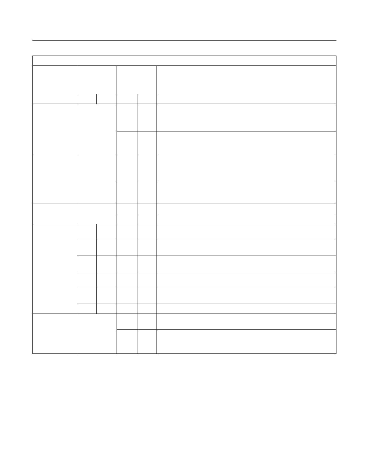
78 SEBU7494-06
Operation Section
Operation
(Table 14, contd)
OPERATION OF CATERPILLAR COMPLEX HYDROMECHANICAL WORK TOOLS
Work Tool
PC3 and PC4
Cold Planers
PC203 and
PC204 Cold
Planers
H63 H63S
Hammers
SG16 Stump
Grinder
SR17
Snowblower,
SR18
Snowblower
and SR21
Snowblower
(1)
The control is not applicab le.
Position
of Fourth
Function
Control
C2 C1
N/A
N/A
N/A
X X
X X
N/A
Position of
Auxiliary
Hydraulic
Control
A1 A2
X
X
X The Hammer does not operate.
X
X The cutting head angles to the right while the cutting wheel rotates. The
X X
X The wo
X
Results
If the sideshift control is in the PLANER position, the drum rotates
clockwise when you view the left side of the cold planer. If the sideshift
control is in the SIDESHIFT position, the cutting head will shift toward the
left side of the cold planer.
If the sideshift control is in the PLANER position, the cold planer does not
X
operate. If the sideshift control is in the SIDESHIFT position, the cutting
head will shift toward the right side of the cold planer.
If the sideshift control is in the PLANER position, the drum rotates
clockwise
when you view the left side of the cold planer. If the sideshift
control is in the SIDESHIFT position, the cutting head will shift toward the
left side of the cold planer.
If the sideshift control is in the PLANER position, the cold planer does not
X
operate. If the sideshift control is in the SIDESHIFT position, the cutting
head will shift toward the right side of the cold planer.
X The Hammer operates.
The cutting wheel rotates counterclockwise when you view the motor
X
side.
The cutt
ing head angles to the left while the cutting wheel rotates. The
Auxiliary Electrical Control is in the ON position.
Auxiliary Electrical Control is in the ON position.
The cut
ting head retracts while the cutting wheel rotates. The Auxiliary
Electrical Control is in the OFF position.
The cutting head extends while the cutting wheel rotates. The Auxiliary
Electrical Control is in the OFF position.
rk tool does not operate.
The auger rotates counterclockwise when you view the snowblower from
X
theleftsideofthemachine.
The auger rotates clockwise when you view the snowblower from the left
side of the machine.
Page 79

SEBU7494-06 79
Operation Section
Parking
Parking
i01992184
Stopping the E ngine
SMCS Code: 1000; 7000
NOTICE
Stopping the engine immediately after it has been
working under load, can result in overheating and accelerated wea
Refer to the following procedure, to allow the engine
to cool, and t
turbocharger housing (if equipped), which could cause
oil coking problems.
1. Operate the engine for five minutes at low idle
with no load.
Note: This allows hot areas in the engine to cool
gradually. This will extend the engine life.
2. Move the joysticks into the HOLD position.
r of the engine components.
o prevent excessive temperatures in the
Stopping the Engine if an
Electrical Ma
SMCS Code: 1000; 7000
1. Lower the work tool to the ground.
2. Raise the armr
the machine.
3. Open the engin
and Maintenance Manual, “Access Doors and
Covers”.
lfunction Oc curs
est. Unfasten the seat belt. Exit
e access door. Refer to Operation
i01871966
3. Turn the eng
position.
4. Relieve the
system. Refer to Operation and Maintenance
Manual, “Work Tool Coupler Operation” for details.
5. Ensure that the engine start switch key is in the
OFFpositionafterthepressureintheauxiliary
hydraulic
6. Cover the exhaust opening after the machine has
cooled dow
ine start switch key to the OFF
pressure in the auxiliary hydraulic
system has been relieved.
n.
Illustration 66
4. Unplug the connector for the fuel shutoff solenoid
that is located on the left side of the engine.
Note: Do not operate the machine until the
malfunction has been corrected.
g00953400
i01872022
Equipment Lowering with
Engine St op ped
SMCS Code: 6700; 7000
Personal
tool falling.
Keep pers
chine when lowering the work tool.
injury or death can result from a work
onnel away from the front of the ma-
Page 80
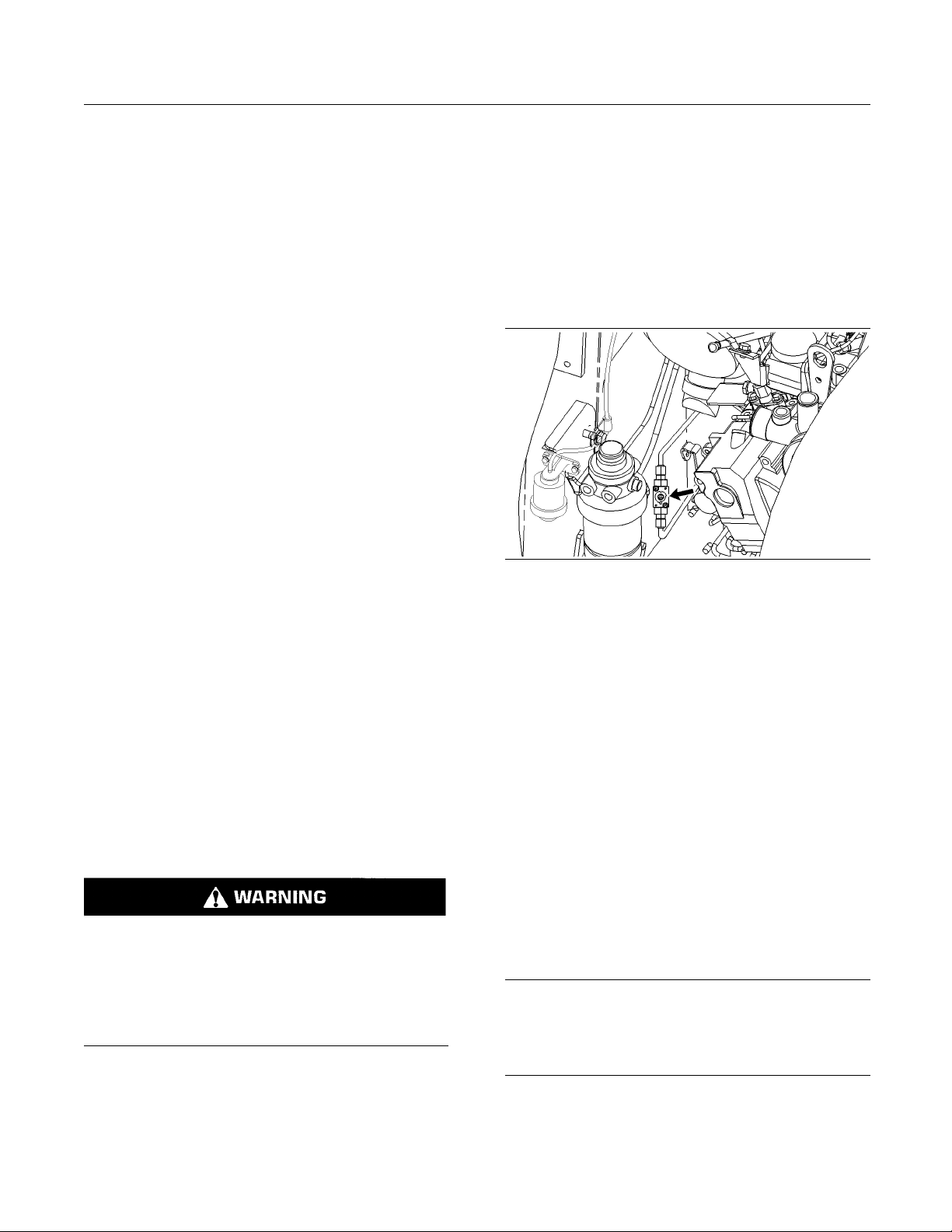
80 SEBU7494-06
Operation Section
Parking
Before lowerin
stopped, clear the area around the equipment of all
personnel. The procedure will vary with the type of
equipment tha
systems use a high pressure fluid or air in order to
raise or lower the equipment. The procedure will
cause high pr
media to be released in order to lower the equipment.
Wear appropriate personal protective equipment and
follow the e
and Maintenance Manual, “Equipment Lowering with
Engine Stopped” in the Operation Section of the
manual.
Lowering th
g any equipment with the engine
t is lowered. Keep in mind that most
essure air, hydraulic fluid, or some other
stablished procedure in the Operation
e Equipment with the
Accumulator Charged
If electrical power is available and the accumulator
is charged, the loader arms can be lowered from the
operator s
1. Fasten the seat belt. Lower the armrest.
2. Turn the engine start switch key to the ON position.
3. Push the pa
tation with the work tool control.
rking brake switch.
Do not go under t
for the loader lift arm in the LOCKED position. Use
the alternate exit if the brace for the loader lift arm
cannot be inst
1. Open the engine access door. Refer to Operation
and Maintena
Covers”.
Note: Make su
front or sides of the machine.
Illustration 67
he raised lift arm without the brace
alledonraisedliftarms.
nce Manual, “Access Doors and
re that there are no people near the
g00953450
4. Slowly move the work tool control to the LOWER
position i
If the loader arms do not lower, the accumulator is not
charged. I
cranking the engine for a period of fifteen seconds.
Repeat step 3 and 4.
If there is no electrical power the loader arms must
be lowered by using the procedure that is explained
next.
Lowering
n order to slowly lower the loader arms.
t is possible to recharge the accumulator by
the Equipment with the
Accumulator Discharged
Persona
pressure.
DO NOT al
Wear appropriate protective equipment while
working
The loader arms must be lowered manually if the
loader a
procedure.
l injury can result from oil under high
low high pressure oil to contact skin.
with high pressure oil systems.
rms cannot be lowered by using the previous
2. The bypass valve is located on the left side of
the engine compartment. Slowly turn the square
stem on the bypass valve in a clockwise direction.
The square stem should be rotated 90 degrees.
Allow the loader arms to lower until the work tool
is on the ground.
3. Slowly turn the square stem on the bypass valve in
a counterclockwise direction until the stem stops.
The square stem should be rotated 90 degrees.
4. Close the engine access door.
5. Make the necessary repairs before you operate
the machine.
i01947381
Machine Storage Pro cedu re
SMCS Code: 7000
NOTICE
If long term storage for a period of time exceeding one
year is necessary, contact your local Caterpillar dealer for the preferred procedure to use in your specific
case.
This machine may be stored for one year or less in
a temperature range of −32 °C (−25.6°F)to43°C
(109.4 °F).
Page 81

SEBU7494-06 81
Operation Section
Parking
To store machin
−20 °C (−4.0 °F) to 43 °C (109.4 °F), refer to Special
Instructions, SEHS9031, “Storage Procedure for
Caterpillar P
To store machines in ambient temperatures between
−32 °C (−26 °F
following publications and topics:
Special Inst
•
Procedure For Caterpillar Products”
Operation an
•
“Cold Weather Recommendations for Caterpillar
Machines”
Note: Do not use the steps that are listed in Special
Instructions, SEHS9031 in order to maintain the fuel
system.
Use the following steps to maintain the fuel system.
1. Drain the fuel tank. Follow the procedure that is
described in Operation and Maintenance Manual,
“Fuel Tank W
2. Drain the water separator and replace the
element. Fo
in Operation and Maintenance Manual, “Fuel
System Water Separator Element - Replace”.
es in ambient temperatures between
roducts”.
)and−21 °C (−6 °F), refer to the
ructions, SEHS9031, “Storage
d Maintenance Manual, SEBU5898,
ater and Sediment - Drain”.
llow the procedure that is described
3. Replace the fuel filter. Follow the procedure that is
described in Operation and Maintenance Manual,
“Fuel Syst
4. Fill the fuel tank so that the fuel tank is at least
20% full w
5. Prime the system by operating the fuel system
priming p
described in Operation and Maintenance Manual,
“Fuel System Priming Pump - Operate”.
6. Start the engine and run at low idle for
approximately 15 minutes in order to allow the
calibrat
system.
7. Turn off t
8. Add .15 mL (0.02 oz) of commercial biocide for
every 1 L
tank. Seal all openings to the fuel tank in order to
prevent evaporation of the preservative.
em Filter - Replace”.
ith Calibration Fluid.
ump. Follow the procedure that is
ion fluid to flush the diesel fuel from the
he engine.
(0.3 US gal) of calibration fluid to the fuel
Page 82
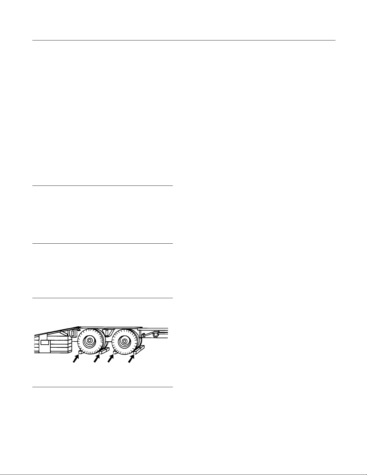
82 SEBU7494-06
Operation Section
Transportation Information
Transportation Information
i01632001
Shipping t he Machine
SMCS Code: 7000
Investigate the travel route for overpass clearances.
Make sure that there will be adequate clearance.
Before you load the machine and before you unload
the machine remove ice, snow, or other slippery
material from the loading dock and from the trailering
surface. Removal of ice, snow, or other slippery
material will help prevent the slipping of the machine
as you load the machine. Removing ice, snow , or
other slippery material will help prevent the machine
from moving in transit.
NOTICE
Obey all state and local laws governing the weight,
width and length of a load.
Make sure the cooling system has proper antifreeze if
moving machine to a colder climate.
Observe all regulations governing wide loads.
Do not use a fork lift to lift the machine. Using a
fork lift to move your machine can result in property
damage.
2. When you use loa
loading ramps have adequate length, adequate
width, and adequate strength. In addition, make
sure that the s
clean. This will help prevent the machine from
sliding in all types of weather conditions. This will
allow the mac
3. Maintain the slope of the loading ramps within 15
degrees of th
4. Minimize any step between the base of the loading
ramps and the
5. Clean the tracks on the machine in order to
prevent any s
Loading the M
1. Position the machine so that the heaviest end of
the machine
2. Use caution when you travel over the areas
around the l
balance point of the machine. Keep the work tool
low.
3. After you load the machine onto the trailer be sure
that the machine is properly positioned on the
trailer be
4. Lower the work tool to the floor of the transport
vehicle.
d.
ding ramps, make sure that the
urface of the loading ramps are
hine to move on the ramps smoothly.
e ground.
ground.
lippage.
achine
is going up the ramps first.
oading ramp joints. Maintain the
Choose the flattest ground when you load the
machine or when you unload the machine.
Illustration 68
1. Before y
wheels or the rail car wheels. Before you unload
the machine chock the trailer wheels or the rail
car whee
ou load the machine chock the trailer
ls.
g00040011
5. Turn the engine start switch key to the OFF
position i
6. Turn the engine start switch key to the ON
position
7. Move all hydraulic control levers while you are
pressing
auxiliary hydraulic control (if equipped) in order to
relieve hydraulic pressure.
8. Move all hydraulic control levers to the HOLD
position.
9. Turn the engine start switch key to the OFF
position. Remove the engine start switch key.
10. Move the armrest to the RAISED position.
Unfasten the seat belt.
11. Attach any vandalism protection.
12. Refer to
Manual, “Lifting and Tying Down the Machine” for
information on tying down the machine.
nordertostoptheengine.
. Push the parking brake switch.
several times on each side of the
the Operation and Maintenance
Page 83

SEBU7494-06 83
Operation Section
Transportation Information
13. Cover the exhau
has cooled down.
st opening when the machine
Unloading the Machine
1. Position the m
drive straight down the loading ramps. Position the
machine so that the heaviest end of the machine
goes down the
2. Use caution when you travel over the areas
around the lo
the balance point of the machine. Keep the work
tool low.
achine so that the machine can
ramps last.
ading ramp joints in order to maintain
i01956162
Roading the Machine
SMCS Code: 7000
Perform a th
Operation and Maintenance Manual, “Daily
Inspection”.
Check with the proper officials in order to obtain the
required licenses and other similar items.
orough Daily Inspection. Refer to
The machine can
hydraulic. The machine can be lifted with a pallet
fork that is not hydraulic. All other work tools must
be removed fro
is lifted.
Do not allow a
machine.
Lifting from
ion 69
Illustrat
Single point lifting eye
be lifted with a bucket that is not
m the machine before the machine
ny personnel in the area around the
a Single Point
g00930025
Ensure that your machine is equipped to comply with
roading regulations.
Travel at a moderate speed. Observe all speed
limitations when you road the machine.
i02112041
Lifting and Tying Down the
Machine
SMCS Code: 7000
NOTICE
Improper lifting or tiedowns can allow load to shift and
can cause injury and damage.
Lifting the Machine
The single point lifting eye and the four-point lifting
group are available for the machine.
For lifting the machine, use properly rated cables and
properly rated slings. Position the crane for a level
machinelift.Donotdragthemachinewithacrane.
Lifting from Four Points
Illustration 70
nt lifting group
Four-poi
When the four-point lifting group is used, the chain
for each l
length.
Please r
the current part number for the lifting device for
your machine. The parts manuals are listed in the
Operati
Information Section”.
eg should be a minimum of 1 m (3.3 ft) in
efer to the Caterpillar Parts Manual for
on and Maintenance Manual, “Reference
g00930032
Page 84
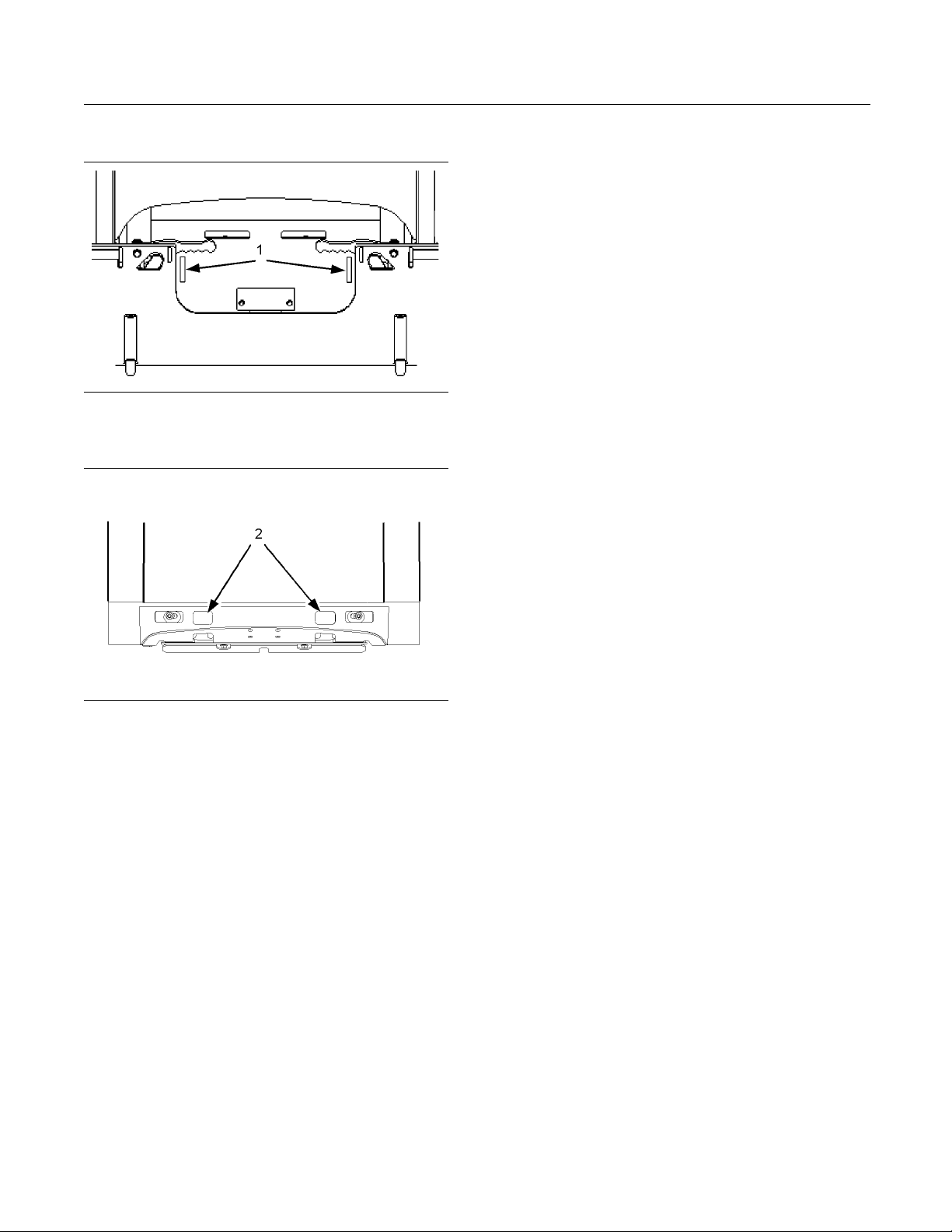
84 SEBU7494-06
Operation Section
Transportation Information
TyingDowntheMachine
Illustration 71
g01019061
The two front eyes (1) are provided for tie-downs.
Illustrat
ion 72
g01019063
The two rear eyes (2) are provided for tie-downs.
Install tie-downs at all four locations. Place chocks in
front of the machine and behind the machine.
Consult your Caterpillar dealer for shipping
instructions for your machine.
Page 85

SEBU7494-06 85
Operation Section
Towing Information
Towing Information
i01821491
Towing the Machine
SMCS Code: 7000
If the machin
lifted onto a trailer in order to be transported. Refer
to Operation and Maintenance Manual, “Lifting and
TyingDownth
Retrieval of
If the machine cannot be lifted, use the following
guidelines i
e is disabled, the machine should be
e Machine” for the lifting procedure.
Machine
n order to retrieve the machine.
Attach the line
•
(1) are located on the front of the machine and
two towing eyes (2) are located on the rear of the
machine. Do no
on the machine. Do not attach the line to only one
towing eye when you are retrieving the machine.
If a single line is used to pull the machine, then the
•
line must be a minimum of 3 m (10 ft). If two lines
areusedtopu
be a minimum of 1.5 m (5.0 ft).
Do not exceed
•
in any direction.
tothetowingeyes.Twotowingeyes
t attach the line to any other point
llthemachine,theneachlinemust
a maximum pull angle of 20 degrees
Illustration 73
Illustration 74
The strength of the line should be at least 1.5 times
•
the gross weight of the machine.
Provide shielding in order to protect the operator
•
if the line breaks.
g00929955
g00930014
Illustration 75
Each of the lines (3) must be a minimum of 1.5 m (5.0 ft).
NOTICE
Do not drag the machine for long distances. Damage
to the trac
ks and to the machine may occur.
g00777765
Page 86

86 SEBU7494-06
Operation Section
Engine Starting (Alternate Methods)
Engine Starting (Alternate
Methods)
i02065056
Engine Start
Start Cables
SMCS Code: 10
Batteriesgiveoffflammablefumesthatcanexplode resulting in personal injury.
Prevent sparks near the batteries. They could
cause vapors to explode. Do not allow the jump
start cable ends to contact each other or the
machine.
Do not smoke when checking ba ttery electrolyte
levels.
Electrolyte is an acid and can cause personal injury if it contacts skin or eyes.
Always wear eye protection when starting a machine with jump start cables.
ing with Jum p
00; 1401; 7000
NOTICE
To prevent dama
trical circuits when you jump start a machine, do not
allow the stalled machine to touch the machine that is
used as the ele
Severely discharged maintenance free batteries do
not fully rech
ing. The batteries must be charged to proper voltage
with a battery charger. Many batteries thought to be
unusable are
Use only equal voltage for starting. Check the battery
and starter v
the same voltage for jump starting. Use of a welder
or higher voltage damages the electrical system. This
machine has a
same voltage for jump starting.
Refer to Spe
Procedure” available from your Caterpillar dealer, for
complete testing and charging information.
1. Engage the parking brake. Lower the work tools
to the ground.
Reference: Refer to Operation and Maintenance
Manual, “Equipment Lowering with Engine
Stopped”.
ge to engine bearings and to elec-
ctrical source.
arge from the alternator after jump start-
still rechargeable.
oltage rating of your machine. Use only
12 volt starting system. Use only the
cial Instruction, SEHS7633, “Battery Test
Improper jump start procedures can cause an explosion resulting in personal injury.
Always connect the positive (+) to positive (+) and
the negative (−)tonegative(−).
Jump start only with an energy source with the
same voltage as the stalled machine.
T urn off all lights and accessories on the stalled
machine. Otherwise, they will operate when the
energy source is connected.
2. Move all control levers to the HOLD or NEUTRAL
position.
3. Turn the engine start switch key to the OFF
position a
OFF position.
4. Move the m
electrical source near the stalled machine so that
the jump start cables reach the stalled machine.
Do not all
other.
5. Stop the e
used as an electrical source. If you are using
an auxiliary power source, turn off the charging
system.
6. Ensure that battery caps on both machines are
tight an
the stalled machine are not frozen.
7. Connect
positive cable terminal of the discharged battery.
Do not al
any metal except for the battery terminals.
nd turn all accessory switches to the
achine that is being used as an
ow the machines to contact each
ngine of the machine that is being
d correctly placed. Ensure that batteries in
thepositivejumpstartcabletothe
low the positive cable clamps to contact
Page 87

SEBU7494-06 87
Operation Section
Engine Starting (Alternate Methods)
8. Connect the oth
cable to the positive cable terminal of the electrical
source.
9. Connect one negative end of the jump start cable
to the negative cable terminal of the electrical
source.
10. Connect the other negative end of the jump
start cable t
the stalled machine. Do not connect the jump
start cable to the battery post. Do not allow
the jump star
cables, the fuel lines, the hydraulic lines, or
any moving parts.
11. Start the engine of the machine that is being used
as an electrical source or energize the charging
system on th
12. Wait at least two minutes before you attempt
to start th
battery in the stalled machine to partially charge.
13. Attempt to
Reference: For the correct starting procedure,
refer to Op
“Engine Starting”.
er positive end of the jump start
otheengineblockortotheframeof
tcablestocontactthebattery
e auxiliary power source.
e stalled machine. This will allow the
start the stalled engine.
eration and Maintenance Manual,
14. After the s
negative jump start cable from the stalled machine.
15. Disconnec
negative terminal of the electrical source.
16. Disconne
positive terminal of the electrical source.
17. Disconne
positive terminal of the stalled machine.
18. Conclude
system of the stalled machine and/or on the
charging system of the stalled machine. Check
the machi
charging system is in operation.
talled engine starts, disconnect the
t the negative jump start cable from the
ct the positive jump start cable from the
ct the positive jump start cable from the
the failure analysis on the starting
ne while the engine is running and the
Page 88

88 SEBU7494-06
Maintenance Section
Maintenance Access
Maintenance Section
Maintenance Access
i01871110
Access Doors and Covers
SMCS Code: 7273-572; 7273-573
Engine Access Door
The engine access door is located on the back of
the machine.
Illustration 78
3. In order to close the engine access door, put the
retaining pin in the stored position.
4. Close the engine access door.
g00953140
Illustration 76
1. Pull the release lever (1) in order to open the
engine access door (2).
g00952785
Note: A pinch point exists between the top of the
engine access door and the radiator guard. Keep
hands away from this area when you close the
engine access door.
i01821601
Cab Tiltin
SMCS Code: 7301-506; 7301-509
Do not go beneath cab unless cab is empty and
support lever is engaged.
Failure to follow the instructions or heed the warnings could result in injury or death.
g
Tilting the Cab Upward
1. Park the machine on level ground.
Note: Empty the water tank (if equipped) before you
tilt the cab.
Illustration 77
2. Put the retaining pin in the locked position so the
engine access door does not close inadvertently.
g00953149
2. Lower the loader arms fully. If you tilt the cab
upward with the loader lift arms in the RAISED
position, you must engage the brace for the loader
lift arms. See Operation and Maintenance Manual,
“Loader Lift Arm Brace Operation” for the process
for engaging the brace for the loader lift arms.
3. Turn the engine start switch key to the OFF
position.
4. Place supports under the rear of the machine in
order to support the machine while the cab is tilted.
Page 89
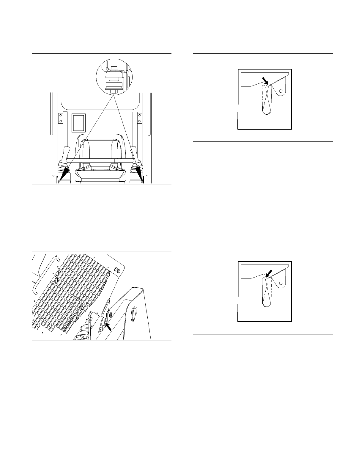
SEBU7494-06 89
Maintenance Section
Maintenance Access
Illustration 79
g00930086
5. Remove the two front bolts for the ROPS.
6. Tilt the cab upward. Stand on the ground when
you tilt the cab.
Note: More than one person may be needed to tilt
the cab.
Illustration 81
The cab support lever is in the ENGAG ED position.
g00952728
7. Make sure that the cab support lever is in the
ENGAGED position.
Tilting the Cab Downward
Note: More than one person may be needed to tilt
the cab.
1. Ensure that all persons are not under the cab.
Remove all of the tools and unsecured items that
are underneath the cab.
Illustration 80
g00954946
tion 82
Illustra
The cab support lever is shown in the DISENGAGED position.
g00952719
2. Tilt the cab upward. Move the cab support lever to
the DISENGAGED position.
3. Tilt the cab downward and install the bolts for
the ROPS. Torque the bolts to 125 ± 20 N·m
(92 ± 15 lb
ft).
4. Remove the supports from the rear of the machine.
Application Guide for Gas Struts
The struts that support the cab are matched to the
weight of the cab. Refer to this chart for the correct
the configuration of the cab is changed.
strut if
Page 90

90 SEBU7494-06
Maintenance Section
Maintenance Access
Table 15
Spring Factoring Table
Part Number Name Factor
142-9310
142-9305
142-9362
195-6723
142-9363
187-3213
142-9302
195-6724
159-5800
195-6726
152-1160
142-91
152-1155
190-8090
166-2550
193-0451
Sum of Factors
OPT
OPTION 2
10
ION 1
Seat and Mounting
(Static)
Seat and Mounting
(Suspension)
CabWindow(Topand
Rear)
CabWindow(Topand
Rear)
Cab Window (Side
Without Heater)
Cab Window (Side With
Heater)
Cab Door (Glass
Window)
Cab Door (Glass
Window)
Cab Door
(Polycarbonate
Window)
Cab Door
(Polycarbonate
Window)
ROPS/F
(FOPS 2)
Machine Lifting (Four
Point)
Machine Lifting (Single
Point)
Machine Lifting (Single
Point)
Wate
Water Tank Gp 3
The right side gas strut
153-2682
The right side gas strut
153-2683
The left side gas strut
153-2683
OPS Guard
rTankGp
0
1
0
0
2
2
4
4
4
4
4
1
3
3
3
Sum of
Factors
0-2
3-6
(continued)
(Table 15, contd)
OPTION 3
OPTION 4
The right side gas strut
153-2682
Theleftsidegasstrut
153-2683
The right side gas strut
153-2682
Theleftsidegasstrut
153-2682
7-9
10+
i01
961564
Loader Lift Arm Brace
Ope
SMCS Code: 6119-011-AB; 6119-012-AB
Loader lift arm brace must be in place when working under raised lift arms.
Failure to follow the instructions or heed the warnings could result in injury or death.
Engage the Lift Arm Brace (Radial
Lift)
1. Empty the work tool. Remove the work tool. Park
Illustration 83
2. Remove the pin that holds the lift arm brace in
3. Lower the lift arm brace to rest on the cylinder
ration
the machine on level ground. Lower lift arms to
the ground. Stop the engine and exit the machine.
00930196
g
the stored position.
housing.
4. Mount the machine. Secure the seat belt and
lower the armrest. Start the engine.
Page 91

SEBU7494-06 91
Maintenance Section
Maintenance Access
5. Raise the lift a
rms until the brace falls onto the
cylinder rod. Slowly lower the lift arms until the
brace stops movement.
Illustrati
on 84
g00952492
6. Stop the engine. Exit the machine. Secure the
retaining p
in through the brace below the cylinder
rod.
Disengage the Lift Arm Brace
(Radial Li
ft)
Illustration 86
g00952609
4. Slowly raise the loader lift arms until the lever
engages the retaining pin.
5. Slowly lower the lift arms to the ground. Stop the
engine. Exit the machine.
6. Raise and secure the brace to the lift arm with the
retaining pin.
7. Install the pivot lever into the STORED position.
Illustration 85
g00952586
1. Remove the retaining pin from the brace and
install the pin (2) in the holding block.
2. Detach and swing the pivot lever (1) clockwise
onto the retaining pin.
3. Mount the machine. Secure the seat belt and
lower the armrest. Start the engine.
Engage the Lift Arm Brace
(Extended Lift)
1. Empty the work tool. Remove the work tool. Park
the machine on level ground. Raise the lift arms to
maximum height.
2. Remain in the seat with the seat belt fastened until
the brace is installed.
Illustration 87
3. A second person must remove the brace from the
storage position by removing the retaining pins.
g009302
02
Page 92

92 SEBU7494-06
Maintenance Section
Maintenance Access
Illustration 88
g00952659
4. The second person should then install the brace
over the rod of one of the lift cylinders.
5. Lower the loader arms slowly until the brace is
held tightly between the rod and the cylinder.
6. Secure the two retaining pins through the brace
below the rod.
Disengage the Lift Arm Brace
(Extended Lift)
1. Mount the machine. Fasten the seat belt. Lower
thearmrestandremainintheseatuntilthebrace
is removed.
2. Slowly raise the lift arms until the brace is free.
3. A second person must remove the retaining pins
and the brace from the rod.
4. Slowly lower the lift arms to the ground.
5. The second person should return the brace to
the storage location. Attach the brace with the
retaining pins.
Illustration 89
g00941929
2. Pull the release lever for the radiator latch. Tilt the
radiator upward.
Illustration 90
g00960146
3. Make sure that the strut lock is in the LOCKED
position.
4. In order to tilt the radiator downward, push the
strut lock to the left.
5. Tilt the radiator downward. Make sure that the
radiator is in the LOCKED position.
i01848989
Radiator Tilting
SMCS Code
1. Open the engine access door. Refer to Operation
and Maint
Covers”.
: 1353-506; 1353-509
enance Manual, “Access Doors and
6. Close the engine access door.
Tilting the Radiator Guard
1. Open the engine access door. Refer to Operation
and Maintenance Manual, “Access Doors and
Covers”.
Page 93

SEBU7494-06 93
Maintenance Section
Maintenance Access
Illustration 91
g00955515
2. Remove the retaining pin from the radiator guard.
Tilt the radiator guard upward.
3. In order to tilt the radiator guard downward,
pull down on the radiator guard and install the
retaining pin.
Page 94

94 SEBU7494-06
Maintenance Section
Lubricant Viscosities and Refill Capacities
Lubricant Viscosities and
Refill Capacities
i02410257
Lubricant Vi
scosities
SMCS Code: 7581
The proper oil viscosity grade is determined by the
minimum outside temperature when the machine
is started. T
he proper oil viscosity grade is also
determined by the maximum outside temperature
while the machine is operated. Use the column that
has the titl
e of “Min” on the table to determine the
oil viscosity grade that is required for starting a cold
machine. Use the column that has the title of “Max”
on the table
to determine the oil viscosity grade for
operating the machine at the highest temperature
that is anticipated. Use the oil with the highest
viscosity
that is allowed for the ambient temperature
when you start the machine.
Table 16
Lubricant Viscosities for Ambient Temperatures
Compartment or System Oil Type and Classification
Cat DEO Multigrade
Engine Crankcase for all
Machines
(1)(2)
Cat DEO SYN
Cat Arctic DEO SYN
Cat ECF-1
API CG-4 Multigrade
Oil
Viscosities
SAE 0W-20
30
0
(6)
40
40
SAE 0W-3
SAE 0W-40 −40 40 −40 104
SAE 5W-30 −30 30 −22 86
(3)
(4)
(5)
SAE 5W-40 −30 50 −22 122
SAE 10W-
SAE 10W-
SAE 15W-
°C °F
Min Max Min Max
−40 10 −40 50
−40 30 −40 86
−18 40 0 104
−18 50 0 122
−9.5 50 15 122
(cont
inued)
Page 95

SEBU7494-06 95
Maintenance Section
Lubricant Viscosities and Refill Capacities
(Table 16, contd)
Lubricant Viscosities for Ambient Temperatures
Compartment or System Oil Type and Classification
Oil
Viscosities
SAE 0W-20 −40 40 −40 104
SAE 0W-30
SAE 0W-40
Cat HYDO
Cat DEO
Cat MTO
Cat TDTO
SAE 5W-30
SAE 5W-40
SAE 10W
Cat TDTO-TMS
SAE 30 10 50 50 122
SAE 10W-
30
SAE 15W-
40
Hydraulic Systems,
Hydrostatic Transmission
Cat DEO SYN
Cat Arctic DEO SYN
Cat Arctic TDTO
Cat ECF-1
Cat BIO HYDO (HEES)
API CG-4
API CF
commercial TO-4
commercial BF-1
Cat MTO
Cat BIO
HYDO
(HEES)
Cat TDTO-
TMS
Idler Wheel Tubes and Bogie
Wheel Tubes
267, 277 and 287
External Lubrication Points Advanced 3Moly
(1)
Supplemental heat is recommended for cold-soaked starts below the minimum ambient temperature. Supplemental heat may be required
for cold-soaked starts that are above the minimum temperature that is stated, de pending on the parasitic load and other factors.
Cold-soaked starts oc cur when the engine has not been operated for a period of time. This allows the oil to become more viscous
due to cooler ambient temperatures.
(2)
API CF oils are not recommended for Caterpillar 3500 Series and smaller Direct Injection (DI) diesel engines. API CF-4 oils are not
recommended for Caterpillar diesel engines.
(3)
Cat Arctic DEO SYN is an S AE 0W30 viscosity grade oil.
(4)
API CI-4, API CI-4 PLUS, and API CH-4 oils are acceptable if the requirements of Caterpillar’s ECF-1 (Engine Crankcase Fluid specification
- 1) are met. API CI-4, API CI-4 PLUS, and API CH-4 oils that have not met the requirements of Caterpillar’s ECF-1 specification may cause
reduced engine life.
(5)
API CG-4 oils are acceptable for use in all Caterpillar machine diesel engines. When API CG-4 oils are used, the oil change interval
should not ex ceed 250 hours. API CG-4 oils that also meet API CI-4, API CI-4 PLUS, or API CH-4 must also meet the requirements
of the Caterpillar ECF-1 specification.
(6)
SAE 10W-30 is the preferred viscosity grade for the 3116, 3126, C7, C-9 and the C9 diesel engines when the ambient temperature is
between -18° C (0° F) and 40° C (104° F).
(7)
Cat Synthetic GO is an SAE 75W-140 viscosity grade oil.
Caterpillar GO
Caterpillar Synthetic GO
(7)
API GL-5
SAE 80W-
90
NLGI Gra
2
de
°C °F
Min Max Min Max
−40 40 −40 104
−40 40 −40 104
−30 40 −22 104
−30 40 −22 104
−20 40 −4 104
−20 40 −4 104
−15 50 5 122
−25 40 −13 104
−40 43 −40 11 0
−20 50 −4 122
-20 40 -4 104
−20 40 −4 104
Page 96

96 SEBU7494-06
Maintenance Section
Lubricant Viscosities and Refill Capacities
Capacities (Refill)
SMCS Code: 7560
Table 17
Approximate Refill Capacities
Compartment
or System
3034 Engine
Crankcase
New Engine
The “ADD” mark
on the Dipstick
3034 Engine
Crankcase
New Engine
The “FULL” mar
on the Dipstick
3034 Engine
Crankcase
Used Engine
The “ADD” mark
on the Dipstick
3034 Engine
Crankcase
Used Engine
The “FULL” ma
on the Dipstick
Hydraulic Tank 35 9.3 7.7
Cooling System 10 2.6 2.2
Fuel Tank
247
Fuel Tank
257
Fuel Tank
267 and 277
Fuel Tank
287
Idler Wheel
Tubes and Bogie
Wheel Tubes
267, 277 and 287
Liters
7
9 2.4 2
k
6 1.6 1.3
8 2.1 1.8
rk
62 16.4 13.6
90 23.8 19.8
80 21.1 17.6
110 29.0 24.1
0.26 0.07 0.06
US
Gallons
1.9 1.5
i02098494
Imperial
Gallons
i01822901
S·O·S Information
SMCS Code: 1000; 7000; 7542-008
S·O·S Services
for Caterpillar customers to use in order to minimize
owning and operating cost. Customers provide
oil samples, c
information. The dealer uses the data in order to
provide the customer with recommendations for
management o
Services can help determine the cause of an existing
product problem.
Refer to Special Publication, SEBU6250, “Caterpillar
Machine Fluid Recommendations” for detailed
informatio
Refer to the Operation and Maintenance Manual,
“Maintenan
sampling location and a service hour maintenance
interval.
Consult your Caterpillar dealer for complete
information and assistance in establishing an S·O·S
program fo
is a highly recommended process
oolant samples, and other machine
f the equipment. In addition, S·O·S
n concerning S·O·S Services.
ce Interval Schedule” for a specific
ryourequipment.
Note: A “new” engine refers to an engine that has
never been run. A “new” engine refers to an engine
that has never been filled with oil.
Page 97

SEBU7494-06 97
Maintenance Section
Maintenance Support
Maintenance Support
i02000840
Welding on Machines and
Engines with Electronic
Controls
SMCS Code: 1000; 7000
Proper welding procedures are necessary in order to
avoid damage to the electronic controls and to the
bearings. When possible, remove the component
that must be welded from the machine or the engine
and then weld the component. If you must weld near
an electronic control on the machine or the engine,
temporarily remove the electronic control in order to
prevent heat related damage. The following steps
should be followed in order to weld on a machine or
an engine with electronic controls.
1. Turn off the engine. Place the engine start switch
in the OFF position.
2. If equipped, turn the battery disconnect switch to
the OFF position. If there is no battery disconnect
switch, remove the negative battery cable at the
battery.
NOTICE
Do NOT use electrical components (ECM or ECM sensors) or electronic component grounding points for
grounding the welder.
3. Clamp the ground cable from the welder to the
component that will be welded. Place the clamp
ascloseaspossibletotheweld.Makesurethat
the electrical path from the ground cable to the
component does not go through any bearing. Use
this procedure in order to reduce the possibility of
damage to the following components:
Bearings of the drive train
•
Hydraulic components
•
Electrical components
•
Other components of the machine
•
4. Protect any wiring harnesses from the debris
which is created from welding. Protect any wiring
harnesses from the splatter which is created from
welding.
5. Use standard welding procedures in order to weld
the materials together.
Page 98

98 SEBU7494-06
Maintenance Section
Maintenance Interval Schedule
i02418872
Maintenance Interval Schedule
SMCS Code: 7000
Ensure that all
instructions are read and understood before any
operation or any maintenance procedures are
performed.
The user is responsible for the performance of
maintenance,
proper lubricants, fluids, filters, and the replacement
of components due to normal wear and aging. Failure
to adhere to p
procedures may result in diminished p erformance of
the product and/or accelerated wear of components.
Use mileage, fuel consumption, service hours, or
calendar time, WHICH EVER OCCURS FIRST,
in order to d
Products that operate in severe operating conditions
may require more frequent maintenance.
Note: Before each consecutive interval is performed,
all maintenance from the previous interval must be
performed
safety information, warnings and
including all adjustments, the use of
roper maintenance intervals and
etermine the maintenance intervals.
.
Hydraulic Syst
Lift Arm and Cylinder Linkage - Lubricate ........... 126
Quick Coupler - Inspect ...................................... 128
Radiator Core -
Seat Belt - Inspect .............................................. 130
Sprocket Retaining Nuts - Check ........................ 132
Tilt Cylinder B
Lubricate ........................................................... 132
Track (Rubber) - Inspect/Adjust .......................... 133
Work Tool - Lubri
Work Tool Mounting Bracket - Inspect ................ 145
em Oil Level - Check ................... 126
Clean ......................................... 128
earings and Bucket Linkage Bearings -
cate .......................................... 143
Every250ServiceHours
Engine Oil Sample - Obtain ................................. 117
Every 250 Service Hours or Monthly
Belts - Inspect/Adjust/Replace ............................ 101
Every500ServiceHours
Hydraulic Oil Sample - Obtain ............................ 124
Every 500 Service Hours or 3 Months
Fuel System Primary Filter (Water Separator)
Element - Replace ............................................ 122
When Required
Battery - R
Battery or Battery Cable - Inspect/Replace ........ 100
Bucket Cutting Edges - Inspect/Replace ............ 106
Bucket Tips
Cab Air Filter - Clean/Replace ............................ 107
Circuit Breakers and Fuses - Reset/Replace ...... 107
Engine Air F
Clean/Replace ................................................... 112
Engine Air Filter Secondary Element - Replace .. 113
Engine Comp
Engine Starting with Jump Start Cables .............. 119
Fuel System Priming Pump - Operate ................ 122
Fuel Tank Cap
Fuel Tank Water and Sediment - Drain ............... 123
Lower Machine Frame - Clean ........................... 127
Oil Filter - I
Track (Rubber) - Remove/Replace ..................... 138
Window Washer Reservoir - Fill .......................... 142
Window Wiper -
Windows - Clean ................................................. 143
ecycle ................................................ 100
- Inspect/Replace ............................ 106
ilter Primary Element -
artment - Clean .............................. 115
- Clean ........................................ 123
nspect ................................................ 127
Inspect/Replace ........................ 143
Every 10 Service Hours or Daily
Axle Bearings - Lubricate .................................... 100
Backup Alarm - Test ............................................ 100
Bogie and Idle
Cooling System Level - Check ............................. 111
Engine Air Filter Service Indicator - Inspect ......... 114
Engine Oil Leve
Fuel System Primary Filter (Water Separator) -
Drain ................................................................. 121
r - Inspect/Replace ....................... 102
l - Check ..................................... 117
Every 500 Servi
Fuel System Filter - Replace .............................. 120
Hydraulic Syste
ce Hours or 6 Months
m Oil Filter - Replace ................. 125
Every 500 Service Hours or 1 Year
Engine Oil and F
ilter - Change ............................ 117
Every 1000 Service Hours
Engine Valve La
sh - Check ................................. 120
Every 1000 Service Hours or 6 Months
Engine Crankca
Rollover Protective Structure (ROPS) and Falling
Object Protective Structure (FOPS) - Inspect ... 129
Every 1000 Serv
Bogie and Idler Oil Level - Check ....................... 105
Hydraulic Syst
Sprocket - Inspect ............................................... 131
Sprocket Bearings - Lubricate ............................ 132
Every 2000 Serv
Refrigerant Dryer - Replace ................................ 129
Every 2000 Servi
Fuel Injection Timing - Check ............................. 120
se Breather - Clean .................... 116
iceHoursor1Year
em Oil - Change ........................... 124
ice Hours
ce Hours or 1 Year
Page 99

SEBU7494-06 99
Maintenance Section
Maintenance Interval Schedule
Every 3000 Serv
Cooling System Coolant Extender (ELC) - Add ... 110
Cooling System
Replace .............................................................. 111
ice Hours or 2 Years
Water Temperature Regulator -
Every 3 Years After Date of Installation or
Every 5 Years After Date of Manufacture
Seat Belt - Replace ............................................. 130
Every 3000 Service Hours or 3 Years
Cooling System Coolant Extender (ELC) - Add ... 110
Every 5000 Service Hours
Engine Crankcase Breather (Closed Circuit) -
Replace .............................................................. 115
Every 6000 Ser
Cooling System Coolant (ELC) - Change ........... 108
vice Hours or 4 Years
Page 100

100 SEBU7494-06
Maintenance Section
Axle Bearings - Lubricate
Axle Bearings - Lub ricate
SMCS Code: 3282-086-BD
S/N: CML1-Up
S/N: CMM1-Up
S/N: CNY1-Up
Illustration 92
247 and 257
i01989568
g00895314
1. Get into the ope
and pull the armrest downward.
2. Start the engi
3. Disengage the parking brake.
4. Move the speed/direction control lever to the
REVERSE position.
The backup alarm (if equipped) should sound
immediately. The backup alarm should continue
to sound unti
is returned to the HOLD position or to the
FORWARD position.
rator’s seat. Fasten the seat belt
ne.
l the speed/direction control lever
i00993589
Battery - Recycle
SMCS Code: 1
Always recycle a battery. Never discard a battery.
Always return used batteries to one of the following
locations:
A battery supplier
•
401-561
Illustration 93
287
Apply lubri
bearings and the front axle bearings.
Repeat the
machine.
cant to the grease fittings for the rear axle
process for the opposite side of the
Backup Alarm - Test
SMCS Code:
7406-081
g01030370
i01017495
An authoriz
•
Recycling facility
•
ed battery collection facility
i01719520
Battery or Battery Cable Inspect/Replace
SMCS Code: 1401-040; 1401-510; 1401-561;
1402-040; 1402-510
1. TurntheenginestartswitchtotheOFFposition.
Turn all switches to the OFF position.
2. Disconnect the negative battery cable from the
starter.
Note: Do not allow the disconnected battery cable to
contact the frame of the machine.
3. Disconnect the negative battery cable at the
battery.
4. Perform the necessary repairs. Replace the cable
or the battery, as needed.
To prevent injury, make sure that no people are
working on
prevent injury, keep the machine under control at all
times.
the machine or near the machine. To
5. Connect the negative battery cable at the battery.
6. Connect the battery cable to the starter of the
machine.
 Loading...