

Page 1

DATA PROJECTOR
EN
XJ-UT Series
XJ-UT312WN*/
XJ-UT352W/XJ-UT352WN*
XJ-F Series
XJ-F11X/XJ-F21XN*/
XJ-F101W/XJ-F211WN*
XJ-S Series
XJ-S400U/XJ-S400UN*/
XJ-S400W/XJ-S400WN*
*Network Models
User’s Guide
In this manual, “XJ-UT Series”, “XJ-F Series” and “XJ-S Series” refer only to the specific models
listed above.
Be sure to read the “Safety Precautions” and “Operating Precautions” and make sure you use this
product correctly.
Keep this manual in a safe place for future reference.
Visit the site below for the latest version of this manual.
https://world.casio.com/manual/projector/
1
Page 2

DLP is a registered trademark of Texas Instruments of the United States.
Microsoft and Windows are registered trademarks or trademarks of Microsoft Corporation in the
United States and other countries.
HDMI, the HDMI Logo and High-Definition Multimedia Interface are trademarks or registered
trademarks of HDMI Licensing Administrator, Inc.
PJLink is a pending trademark or a registered trademark in Japan, the United States, and other
countries and areas.
Crestron is a registered trademark of Crestron Electronics, Inc. of the United States.
Crestron Connected is a trademark of Crestron Electronics, Inc. of the United States.
Other company and product names may be registered trademarks or trademarks of their
respective owners.
Portions of this product are based in part on the work of the Independent JPEG Group.
The contents of this User’s Guide are subject to change without notice.
Copying of this manual, either in part or its entirety is forbidden. You are allowed to use this
manual for your own personal use. Any other use is forbidden without the permission of CASIO
COMPUTER CO., LTD.
CASIO COMPUTER CO., LTD. shall not be held liable for any lost profits or claims from third
parties arising out of the use of this product or this manual.
CASIO COMPUTER CO., LTD. shall not be held liable for any loss or lost profits due to loss of
data due to malfunction or maintenance of this product, or any other reason.
The sample screens shown in this manual are for illustrative purposes only, and may not be
exactly the same as the screens actually produced by the product.
2
Page 3

Contents
Safety Precautions.......................................................... 7
Operating Precautions.................................................. 13
About the Light Source Unit.................................................................13
Projector Light Emission (XJ-UT Series) ..............................................13
Do not block light output or look directly into the lens!
(XJ-F Series/XJ-S Series) .....................................................................14
Laser and High Temperature Precautions (See the label on the
projector) ..............................................................................................15
Other Precautions ................................................................................18
Precaution when Handling the Projector after Use ..............................20
Getting Ready................................................................ 21
Unpacking ............................................................................................21
Operation Flow to Projection................................................................21
General Guide ......................................................................................23
Key and Indicator Panel .......................................................................25
Back Terminals.....................................................................................26
Placing the Projector on a Desk or on the Floor ..................................28
Adjusting the Vertical Angle of the Projector .............................................................28
Setup Precautions ..................................................................................................... 30
Connecting with Another Device..........................................................31
Connecting a Computer ............................................................................................31
Connecting to a Video Device ................................................................................... 32
Outputting Audio from the Projector to Another Device............................................ 34
Connecting a Microphone (XJ-UT Series, XJ-F21XN, XJ-F211WN, XJ-S400UN,
XJ-S400WN) ..............................................................................................................35
Connecting to a Network with a LAN Cable (Network Models Only) ........................ 35
Connecting a Wireless Adapter (Network Models Only)............................................36
LOGO Terminal (Firmware Updates, User Logo Transfers) ....................................... 36
Connecting a Scientific Calculator (Network Models Only) ....................................... 37
SERIAL Terminal (Projector Control Using Commands)............................................37
USB Power ................................................................................................................38
3
Page 4

Cover Included with the YW-41 Wireless Adapter ...............................38
Attaching and Removing the Cable Cover (XJ-UT Series) ...................39
Remote Controller ................................................................................40
Operating the Projector................................................ 41
Turning the Projector On or Off............................................................41
To turn on the projector ...........................................................................................41
To turn off the projector ........................................................................................... 41
Direct Power On ...................................................................................................... 41
Auto Power Off........................................................................................................42
Auto Projection Off .................................................................................................. 42
Selecting an Input Source (INPUT).......................................................42
Resolution ...............................................................................................................42
Using Auto Input Search............................................................................................ 43
To trigger an auto input search operation manually..................................................43
Auto Input Search Following Power On....................................................................43
Auto Input Search Sequence...................................................................................44
Changing the Input Source Manually......................................................................... 45
Relationship Between Image Input and Audio Input .................................................45
Using Auto Projection Off.....................................................................47
Enabling and Disabling Auto Projection Off...............................................................48
Auto Projection Off Projection Light Control ............................................................. 48
Basic Image and Audio Operations During Projection.........................49
Flipping the Projected Image Horizontally (Mirror Mode).....................51
Light Control.........................................................................................52
Digital Screen Shift...............................................................................53
Projecting a Template ..........................................................................53
To project a template............................................................................................... 53
To change the template type (XJ-UT352W, XJ-F11X, XJ-F101W, XJ-S400U,
XJ-S400W) .............................................................................................................. 54
To change the template type (Network Models) ....................................................... 54
Test Pattern Projection.........................................................................55
Control Panel Lock...............................................................................55
Configuring Remote Control ID and Projector ID Settings...................56
Using the Countdown Timer (TIMER)...................................................56
Showing and Hiding the Countdown Timer.............................................................. 56
4
Page 5

Using the Presentation Timer (TIMER) .................................................58
To display the timer ................................................................................................. 58
To display the timer function menu .......................................................................... 58
To configure timer settings....................................................................................... 58
Timer Operations ..................................................................................................... 59
Using the Setup Menu (MENU) ............................................................60
Setup Menu Settings .................................................................................................60
Using a Password ................................................................................67
Configuring Password Settings ................................................................................ 67
Using the Password Feature.................................................................................... 68
If you forget your password... .................................................................................. 68
Cleaning the Projector.................................................. 69
Cleaning the Projector Exterior ............................................................69
Cleaning the Lens.................................................................................69
Cleaning Vents .....................................................................................69
Troubleshooting ............................................................ 70
Normal Operation Indicators ................................................................70
Error Indicators and Messages ............................................................71
Error Messages ....................................................................................................... 71
Indicator Status When an Error Occurs.................................................................... 71
Projector Troubleshooting....................................................................73
Checking the Serial Number and Board Number.................................75
Appendix ........................................................................ 76
Supplying USB Power to Another Device ............................................76
Mounting the Projector on a Wall (XJ-UT Series).................................77
Hanging the Projector from a Ceiling (XJ-F Series, XJ-S Series).........77
Using the MONITOR OUT Terminal (XJ-UT Series,
XJ-S400UN, XJ-S400WN) ....................................................................78
Projection Distance and Screen Size ...................................................79
Aspect Ratio Setting and Projection Image .........................................82
Supported Signals................................................................................84
Projector RS-232C Control ..................................................................85
5
Page 6

Specifications................................................................ 88
All Series...............................................................................................88
XJ-UT Series ........................................................................................89
XJ-F Series ...........................................................................................90
XJ-S Series...........................................................................................91
TCO Certified Document URL...................................... 93
6
Page 7
Safety Precautions
Thank you for selecting this CASIO product. Be sure to read these “Safety Precautions” before trying
to use it. After reading this User’s Guide, keep it in a safe place for future reference.
About safety symbols
Various symbols are used in this User’s Guide and on the product itself to ensure safe use, and to
protect you and others against the risk of injury and against material damage. The meaning of each of
the symbols is explained below.
Icon Examples
*
Danger
Indicates something that creates a major risk of death or serious personal
injury.
*
Warning
Indicates something that creates a risk of death or serious personal injury.
*
Caution
Indicates something that creates a risk of minor personal injury or physical
damage.
’
A triangle indicates a situation against which you need to exercise caution. The example
shown here indicates you should take precaution against electric shock.
!
A circle with a line through it indicates information about an action that you should not
perform. The specific action is indicated by the figure inside the circle. The example shown
here means disassembly is prohibited.
$
A black circle indicates information about an action that you must perform. The specific
action is indicated by the figure inside the circle. The example shown here indicates you must
unplug the power cord from the power outlet.
*
Precautions During Use
Warning
Adult supervision is required whenever
there are young children present and
especially when there is the possibility
of young children coming into contact
with the projector.
Battery Precautions
Should fluid leaking from a battery get
on your skin or clothing, immediately
rinse it off with clean water.
Battery fluid getting into the eyes
creates the risk of eyesight loss, etc.
Rinse the eyes and then immediately
contact a physician.
Abnormalities (Smoke, Odor, Heat
Generation, etc.)
Do not use the product if it is emitting
smoke, odor, heat, or exhibiting any
other abnormality. Do not use the
product after it has been dropped or
otherwise damaged.
Doing so creates the risk of fire and
electric shock. Immediately perform the
steps below.
1. Unplug the power plug from the power outlet.
2. Contact your original retailer or a CASIO
Service Center.
7
Page 8

Do not use the product if it is
malfunctioning.
Do not continue using the product if its
display is abnormal or if it is
malfunctioning.
Continued use creates the risk of fire
and electric shock. Immediately perform
the steps below.
1. Turn off power.
2. Unplug the power plug from the power outlet.
3. Contact your original retailer or a CASIO
Service Center.
Power Cord
Observe the precautions below in
order to avoid power cord fire and
electric shock.
• Use only the included power cord.
• Do not plug the power cord into an
outlet with the wrong voltage rating.
• Ground the power cord before
plugging it into a power outlet.
• Unground the power cord after
unplugging it from the power outlet.
• Should the power cord become
damaged, contact your original retailer
or a CASIO Service Center.
• Use the included power cord with this
product only.
• Do not plug the power cord into an
outlet with the wrong voltage rating.
• Do not plug into an overloaded
extension cord or power outlet.
• Do not share the outlet supplying
power to the product with other
devices.
If you are using an extension cord,
make sure that the ampere rating of the
extension cord is appropriate for this
product.
• Do not cover the power cord with a
blanket or other material during use,
and keep it away from heating devices.
• Do not place heavy objects on the
power cord and do not leave it bundled
during use.
• Do not locate any objects in the vicinity
of the power plug and keep it easily
accessible so it can be unplugged in
case of an emergency.
• Do not subject a power cord to heat or
attempt to modify it, and avoid
damaging it.
• Do not subject the power cord to
excessive bending, twisting, or pulling.
• Make sure the power cord is not
pinched between the wall and the rack
or table where the product is located,
and never cover the power cord with a
cushion or other object.
Do not touch the plug with wet hands.
Doing so creates the risk of electric
shock.
Avoiding Water and Foreign Matter
Do not allow water, other liquids
(sports drinks, seawater, animal or pet
urine, etc.), or foreign objects (metal
fragments, etc.) to get into the
product. Should any such matter get
into the product, immediately perform
the steps below.
Continued use creates the risk of fire
and electric shock.
1. Turn off power.
2. Unplug the power plug from the power outlet.
3. Contact your original retailer or a CASIO
Service Center.
Do not locate a flower vase or other
liquid container on top of or next to the
product.
Liquid spilling from a container creates
the risk of fire and electric shock.
Disassembly and Modification
Do not attempt any disassembly or
modification.
For any internal inspection,
adjustment, or repair, contact your
original retailer or a CASIO Service
Center.
The product contains a large number of
high-voltage components that create
the risk of electric shock and burn
injury.
8
Page 9

Suffocation and Choking Risks
Vent Blockage
Do not allow anyone to play with the
plastic bags used for product
packaging.
Plastic bags create the risk of
suffocation when placed over the head,
when swallowed, etc.
Particular care is required in areas
where young children are present.
Dropping and impact
Continued use of the projector after it
has been damaged by dropping or
other mistreatment creates the risk of
fire and electric shock. Immediately
perform the following steps.
1. Turn off the projector.
2. Unplug the projector.
3. Contact your original dealer or authorized
CASIO service center.
Disposal by burning
Never try to dispose of the projector by
burning it. Doing so can cause an
explosion, which creates the risk of fire
and personal injury.
Avoid Looking into the Light
Do not look directly into the lens, the
intake or exhaust vents while the light
is on.
The strong light emitted by the light
source creates the risk of eye damage.
Do not allow blocking of the intake or
exhaust vents.
Be sure to observe the precautions
below.
Blocked vents causes internal heat
buildup, which creates the risk of fire
and malfunction.
• XJ-UT Series: Maintain a distance of at least 6
cm (2.4 inches) between the front of the
projector (from which light is being emitted)
and the projection surface (screen). Maintain a
distance of at least 30 cm (11.8 inches)
between surfaces and the other sides of the
projector.
• XJ-F Series/XJ-S Series: Allow at least 30 cm
(11.8 inches) between the projector and walls.
• Do not insert the product into a space where
air circulation is poor, and do not cover it with
a blanket, etc.
• Do not use the product while it is on a carpet,
blanket, towel, or other soft material, or on a
seat with soft covering. Use the product on a
hard, flat surface.
Keep the Cabinet Closed
Do not try to open the projector
cabinet.
Doing so creates the risk of electric
shock.
Intake and Exhaust Vents
Do not touch the intake and exhaust
vents during projection, and do not
place any plastic or other objects or
material close to intake/exhaust vents.
Also, do not place the product on top
of such materials.
Doing so creates the risk of burn injury,
and deformation and discoloration of
the object or material.
9
Page 10

Objects Blocking Projection
Location
Make sure there are no objects that
can block the light in front of the lens
while projecting.
Such conditions create the risk of fire.
Aquarium, Other Water Tank
Make sure there is no aquarium or any
other type of water tank that can
produce a lens effect in front of the
lens while projecting.
Such conditions create the risk of fire.
Lens
Do not touch the lens with your hand.
Doing so creates the risk of burn injury
and accident.
Storage and Operation Locations
Do not store or use the product in any
of the locations described below.
Doing so creates the risk of fire and
electric shock.
•Areas subjected to large amounts of moisture
and dust
• Food preparation areas, near a humidifier, or
in areas where the product is exposed to oil
smoke or water vapor
• Areas where there is strong vibration
• Other areas where there are high or low
temperatures (Operating temperature range:
5°C to 35°C)
Do not place the product on an
unsteady platform, on a high shelf, or
in any other unstable location.
Dropping and tipping over creates the
risk of personal injury.
Do not place heavy objects on the
product or climb up on it.
Doing so creates the risk of fire and
electric shock.
Do not leave the product in a lavatory,
a bathroom, or anywhere else there is
the chance that it will become wet.
Moisture creates the risk of fire and
electric shock.
Lock the wheels. (When using the
product on a handcart, etc.)
Dropping and tipping over create the
risk of personal injury.
In the case of a lightning storm, do
not touch the device plugged into
the power outlet
Lightning creates the risk of electric
shock.
Remote controller
Never try to take the remote controller
apart or modify it in any way. Doing so
creates the risk of electric shock, burn
injury, and other personal injury. Be sure
to leave all internal inspection,
adjustment, and repair up to your
original dealer or authorized CASIO
service center.
Never allow the remote controller to
become wet. Water creates the risk of
fire and electric shock.
10
Page 11

YW-41 wireless adapter
*
Keep the wireless adaptor out of the
reach of small children.
Accidental swallowing of the wireless
adaptor creates the risk of suffocation
and personal injury.
Radio waves emitted by the YW-41
wireless adapter
Never use this product inside of an
aircraft or medical facility, or in any
other location where use of such
devices is prohibited. Radio waves can
have an effect on the operation of
electronic equipment and medical
equipment, and cause accidents.
Do not use this product in the vicinity of
high-precision electronic instruments or
electronic devices that handle weak
radio signals. Radio waves can have an
effect on the operation of such
equipment, and cause accidents.
• If you are using a pace maker or any other
electronic medical device, be sure to consult
your physician or device manufacturer before
using this product.
Do not use flammable gas sprays
nearby
Do not spray flammable gas into or in
the vicinity of the projector. The gas
may ignite and create the risk of fire.
Effect on Other Electronic Devices
When using the product in a medical
facility or aircraft, follow the
instructions of local personnel and
crew concerning use of such devices.
Do not use the product in an area
where use of such devices is
prohibited.
Electromagnetic waves and other
signals emitted by this product may
affect measuring instruments and
create the risk of accident.
Do not use the product in the vicinity
of high-precision electronic equipment
or any electronic equipment that
handles weak signals.
Doing so can cause misoperation and
other problems in the electronic
equipment, and creates the risk of
accident.
Keep this product away from the chest
area of any individual fitted with a
cardiac pacemaker.
Cardiac pacemakers and similar
devices can be affected by
electromagnetism. Should anyone fitted
with a cardiac pacemaker or other
medical device ever experience any
abnormality, move the product away
and contact a physician.
Caution
Power Cord
Observe the precautions below in
order to avoid power cord fire and
electric shock.
• Insert the power plug into the outlet as
far as it will go.
• At least once a year, unplug the power
plug from the power outlet and use a
dry cloth to wipe away any dust
buildup from the area between the
prongs of the plug.
• Before moving the product, turn it off
and unplug from the power outlet.
• After use, unplug the power plug from
the power outlet.
• If you do not plan to use the product
for a long time, unplug from the power
outlet.
• When unplugging the power plug, do
not pull on the power cord. Grasp the
plug.
• Do not use detergent when cleaning
the power cord, especially the power
plug and jack parts.
11
Page 12

Backup of important data
Be sure to keep separate written
records of all data stored in projector
memory. Memory data can be lost due
to breakdown, maintenance, etc.
Battery Precautions
Observe the precautions below.
Failure to do so can cause a battery to
rupture, creating the risk of fire,
personal injury, and soiling of nearby
objects by leaking fluid.
• Load a battery with its poles (plus (+)
and minus (–)) facing correctly.
• If you do not plan to use the product
for a long time, remove batteries.
• Replace the batteries as soon as
possible after they go dead.
• Do not use a battery whose covering
has been removed.
• Do not try to take a battery apart and
never allow a battery to become
shorted.
• Do not charge a non-rechargeable
battery.
• Do not mix old and new batteries.
• Do not mix different battery types.
• Do not expose a battery to heat or
throw it into fire.
• Use only the specified type of battery.
Other
Allowing dust to build up inside the projector by
not cleaning it for long periods creates the risk of
fire and accident, and can cause loss of
projection luminosity. Contact your original
dealer or authorized CASIO service center once
a year about having the interior of the projector
cleaned. Note that you will be charged for
cleaning.
User Maintenance
Before cleaning the product, turn off
power and unplug the AC adaptor from
the power outlet.
Failure to do so creates the risk of
electric shock.
Leaving the AC adaptor plugged in
creates the risk of damage to the power
cord, fire, and electric shock.
Once a year, request internal cleaning
(charged separately) from your original
retailer or a CASIO Service Center.
Long-term dust build-up creates the
risk of fire and malfunction.
Magnetism
This projector has a magnet inside.
Because of this, it should not be used in
the vicinity of anyone wearing a
pacemaker or any other electric medical
device. Should any problem arise, move
the projector away from the person
experiencing the problem and consult a
physician.
Keep the projector away from floppy
disks, magnetic cards, magnetic tapes,
prepaid cards, checks, and any other
media that uses magnetic recording.
The projector can corrupt data recorded
on magnetic media.
12
Page 13
Operating Precautions
About the Light Source Unit
The projector’s light source unit uses a laser and LED.
The life of the light source unit is rated at approximately 20,000 hours. The actual life will depend on
use conditions, the settings configured on the setup menu, and differences between each individual
light source unit.
The light source unit is warranted for the period noted on the warranty certificate or for 6,000 hours,
whichever comes first.
The failure of the light source unit to light or a noticeable drop in light source unit brightness
indicates the end of the light source unit’s life. Contact your original dealer or authorized CASIO
service center for replacement. Note that problems caused by unauthorized projector disassembly
or modification are not covered by the warranty and are not eligible for repair by CASIO.
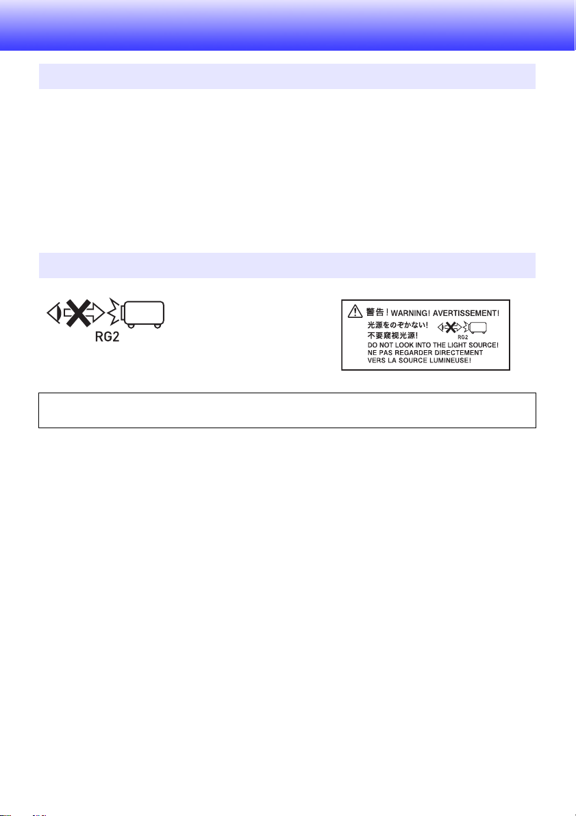
Projector Light Emission (XJ-UT Series)
Never look directly into the lens while the light is on.
Particular care is required when children are present.
RISK GROUP 2
As with any bright light source, do not stare into the beam, RG2 IEC 62471-5:2015.
13
Page 14
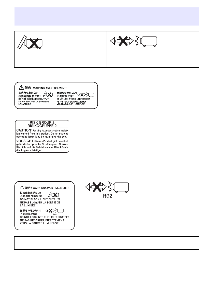
Do not block light output or look directly into the lens! (XJ-F Series/XJ-S Series)
• Never block light output while the light is on. • Never look directly into the lens while the light
is on. Particular care is required when
children are present.
■ XJ-F Series
Projection Lamp Caution
This label is a “RISK GROUP 2” caution label required under the
IEC62471 standard.
RISK GROUP 2 (Moderate Risk) lamps exceed the limits of Exempt
Group (No Hazard) standards. Do not stare at the operating lamp
during projection. Doing so may be harmful to the eyes.
Avoid looking into the projection lens on the front of the projector
when turning on power, which creates the risk of looking directly at
the operating lamp.
■ XJ-S Series
Never look directly into the lens while the light is on.
Particular care is required when children are present.
RISK GROUP 2
As with any bright light source, do not stare into the beam, RG2 IEC 62471-5:2015.
14
Page 15
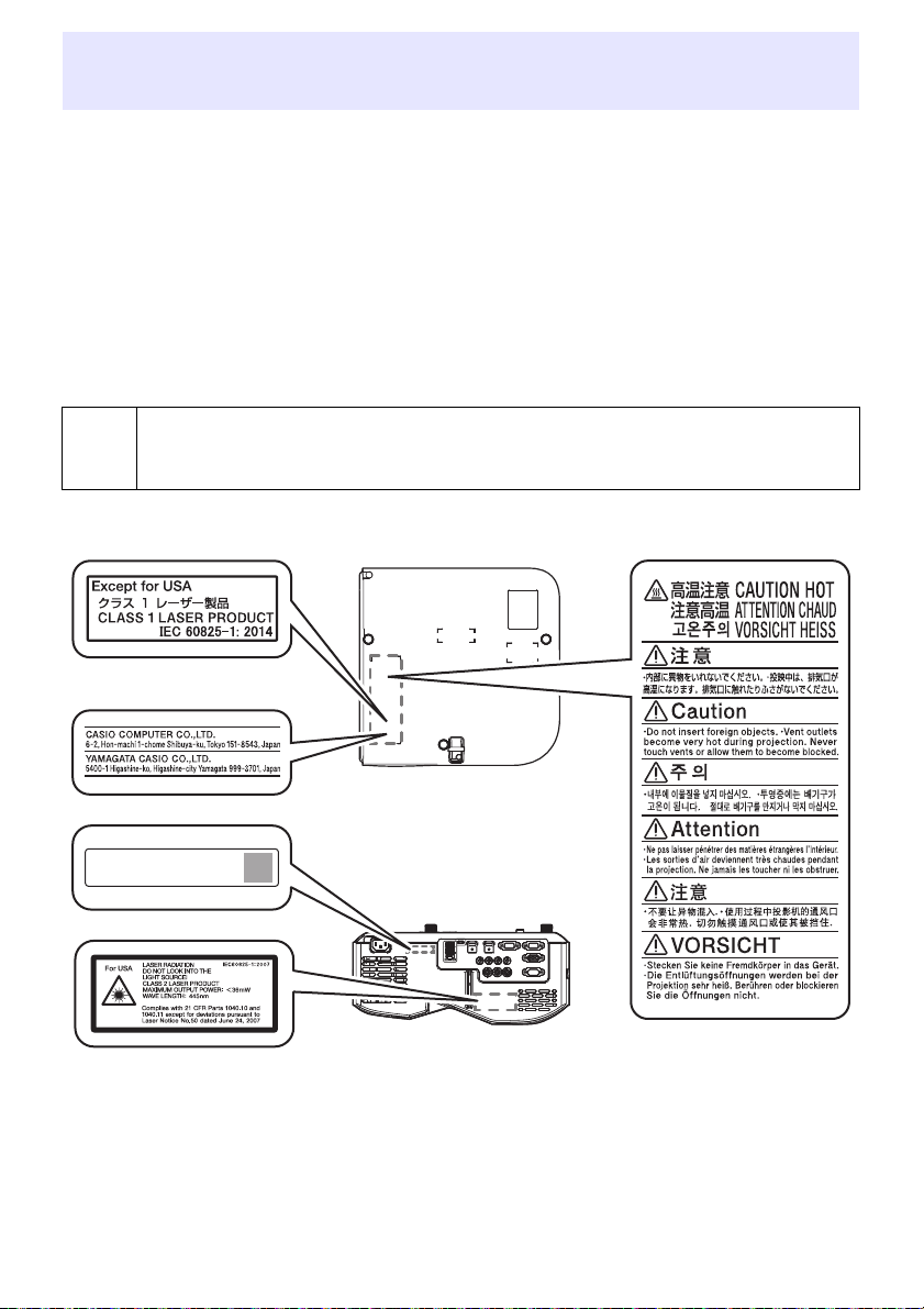
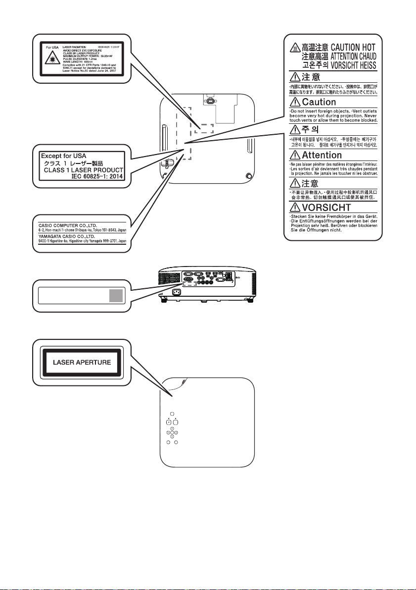
Laser and High Temperature Precautions (See the
Label
Label
Bottom
Side Label
label on the projector)
Laser Precautions (Label , Label , Label , Label )
Non- U.S. Label : This projector is a Class 1 laser device that conforms to IEC 60825-1: 2014.
U.S. Label
U.S. Label
This projector has a built-in laser module. Disassembly or modification is very dangerous and
should never be attempted.
Any operation or adjustment not specifically instructed by the user’s guide creates the risk of
hazardous laser radiation exposure.
Vent Outlet Precautions (Label )
&
■ XJ-UT Series
: This projector is a Class 2 laser device that conforms to IEC 60825-1: 2007.
, Label : This projector is a Class 3R laser device that conforms to IEC 60825-1: 2007.
Vent outlets become very hot during projection. Never touch vents or allow them to
become blocked.
Do not insert foreign objects.
XJ-OOO XXXXXXXXXX-XXXXXX
Production Date: YYYY/MM
Wavelength : 445 nm
Beam divergence : 54 mrad
Pulse duration : 0.8 ms (120 Hz)
Maximum power or energy output : 36.0 mW
15
Page 16

XJ-F Series
XJ-OOO XXXXXXXXXX-XXXXXX
Production Date: YYYY/MM
Wavelength : 445 nm
Beam divergence : 60.7 mrad
Pulse duration : –
Maximum power or
energy output : 40.47 mW
Label
Label
Bottom
Rear
Label
16
Page 17
XJ-S Series
XJ-OOO XXXXXXXXXX-XXXXXX
Production Date: YYYY/MM
Wavelength : 455 nm
Beam divergence : 89 mrad
Pulse duration : 1.2 ms (120 Hz)
Maximum power or
energy output : 59.33 mW
Label
Label
Bottom
Rear
Label
Top
Label
17
Page 18

Other Precautions
This projector is made of precision components. Failure to observe the following precautions can
result in inability to correctly save data and malfunction.
Never use or store the projector in the following locations. Doing so creates the
risk of malfunction of and damage to the projector.
Locations subjected to electrostatic charge
Locations subjected to temperature extremes
Locations where there is extreme moisture
Locations subjected to sudden temperature changes
Locations where there is a lot of dust
On a shaky, slanted, or otherwise unstable surface
Locations where there is the danger of getting wet
Locations where there are large amounts of oil smoke or other smoke
Locations where there is the risk of salt damage
Locations where corrosive gas (such as the sulfur gas at hot springs) is generated
Never use the projector in an environment where large amounts of oil smoke are
present. In particular, ceiling or wall mounting the projector in an environment
where large amounts of oil smoke are present can result in the projector falling
from its mounting.
Ensure that the remote control signal receiver is not exposed fluorescent light,
sunlight, or other strong light. Strong light can cause malfunction.
Avoid using the projector under the following conditions. Such conditions create
the risk of malfunction of and damage to the projector.
Avoid areas subject to temperature extremes (operating temperature range is 5°C to 35°C (41°F
to 95°F)).
Never place heavy objects on the projector or climb on top of the projector.
Never insert or allow foreign objects to drop into the projector.
Never place a vase or any other container of water on top of the projector.
Whenever setting the projector down or performing any operation that involves
moving or reorienting it, take care that you do not pinch your fingers under the
projector.
To avoid running down the batteries, store the remote control unit so its keys are
not pressed inadvertently.
Never leave dead batteries inside the remote controller for a long time.
Dead batteries can leak, which leads to malfunction of and damage to the remote controller. Be sure
to replace the batteries at least once every one year, no matter how much you use the remote
controller during that time.
Clean with a soft, dry cloth.
When very dirty, use a soft cloth that has been dampened in a weak solution of water and a mild
neutral detergent. Wring all excess water from the cloth before wiping. Never use thinner, benzine, or
any other volatile agent to clean the projector. Doing so can remove its markings and cause staining of
the case.
Missing Screen Dots
Though this projector is manufactured using the most advanced digital technology available today,
some of the dots on the screen may be missing. This is normal, and does not indicate malfunction.
18
Page 19

Never subject the projector to strong impact while it is projecting.
If the projector is accidentally subjected to strong impact, the projection image will momentarily go
blank. The image will reappear after some time, but it may be the wrong color or it may be
accompanied by an error message.
If the projected image is the wrong color, re-select the current input source. If this does not return the
projected image to its proper color, turn projector power off and then back on again.
If the image reappears with an error message, correct the problem in accordance with the indicator
explanations under “Error Indicators and Messages” (page 71).
Use a power outlet near the projector. Always use the projector so that the power
cord can be easily unplugged.
The YW-41 Wireless Adapter (included or purchased separately) supports the
2.4GHz band only.
Keystone Correction and Image Quality
Performing keystone correction causes the image to be compressed before it is projected. This can
result distortion of the image or a loss of image quality. If this happens, change orientation of the
projector and/or screen so it conforms as much as possible to the illustration under “Placing the
Projector on a Desk or on the Floor” (page 28).
If image quality is the highest priority, turn off keystone correction and position the projector so it is
pointed straight at the screen.
Even if your projector is still within the warranty period, you will be charged for repair if a problem is
due to running the projector non-stop for very long periods (like 24 hours) or if the projector was set
up and used without following the “Setup Precautions” (page 30).
Use under high ambient temperature or in environments subjected to large amounts of dust, oil
smoke, tobacco smoke, or other types of smoke can shorten the replacement cycles and require
more frequent replacement of the optical engine and other components. Note that you are charged
for such replacement. For details about replacement cycles and fees, contact an authorized CASIO
service center.
Condensation
Moving the projector from a cold room to a heated room, turning on a heater in a cold room, and other
similar conditions can cause condensation (fogging) to form on the projector lens and/or inside the
projector, which will make the projected image appear out of focus and can lead to malfunction and
other trouble. If this happens, turn off the projector and wait for a while until the condensation clears
naturally. When it does, you will be able to project images normally.
Power Supply to External Equipment
Turning off projector power also cuts power being supplied to external equipment. Note that power
being supplied is also cut when the projector is turned off due to restarting by its self-check function
or Auto Power Off, due to some error, or for any other reason. Depending on the external equipment
being used, cut off of the power supply may cause data that is being edited to be lost or corrupted.
Make it a habit to frequently save data on external equipment being powered by the projector. Note
that CASIO COMPUTER CO., LTD. shall be held in no way liable for any loss or corruption of data.
Disposing of batteries
Make sure that you dispose of used batteries in accordance with the rules and regulations in your local
area.
Be sure to follow all applicable local laws and regulations, and do not dismantle the
projector when disposing of it.
19
Page 20
*
Observe the precautions below. Failure to do so can cause the battery to explode
or leak flammable liquid or gas.
Use only the type of battery that is specified for this product.
Do not burn a battery or dispose of it in an incinerator, or by mechanical crushing or cutting.
Do not subject a battery to excessively high or low temperatures during use, storage, or
transport.
Do not subject a battery to excessively low barometric pressure during use, storage, or
transport.
Battery Precautions
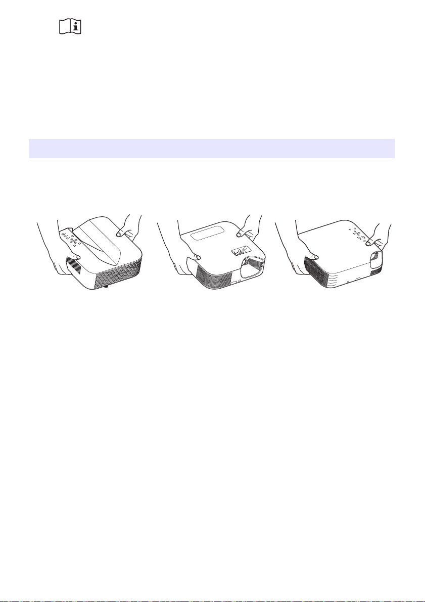
Precaution when Handling the Projector after Use
The projector’s exhaust vents and the area around the vents become very hot during operation, and
will still be hot immediately after turning off the projector. When moving the projector, be sure to first
turn off power and unplug its power cord from the power outlet. Hold the projector as shown in the
illustration below.
XJ-UT Series XJ-F Series XJ-S Series
20
Page 21
Getting Ready
Unpacking
As you unpack the projector, check to make sure that all of the items listed below are present.
Projector
Wireless remote controller YT-161
Test Batteries (AAA-size × 2)
AC Power Cord
Cable cover (XJ-UT Series only)
Wireless adapter YW-41 (XJ-UT312WN only)
“Where to find the User’s Guide” sheet
Warranty
Operation Flow to Projection
This section explains the operational flow up to the point that projection is started.
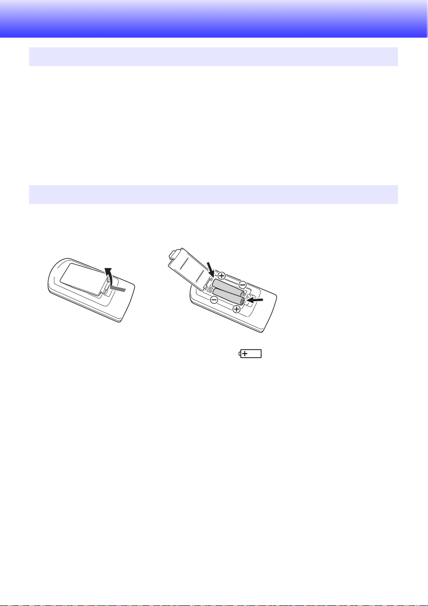
1.
Load the test batteries that come with the projector into the remote controller.
Use only alkaline batteries to power the remote controller.
Orient batteries as shown by the polarity figures ( ) inside the battery compartment.
2.
Place the projector onto a table, desk, or stand that is level and firm, making
sure that you allow enough room around it.
“Safety Precautions” (page 7), “Operating Precautions” (page 13)
“Placing the Projector on a Desk or on the Floor” (page 28), “Setup Precautions” (page 30)
You will need to purchase special hardware to mount this projector on a wall. For details, contact
the retailer where you purchased the projector.
3.
Adjust the vertical angle of the projector.
“Adjusting the Vertical Angle of the Projector” (page 28)
4.
Use the supplied power cord to plug the projector into a power outlet.
5.
Connect the projector to an image output device and/or audio output device, and
then turn on each device.
“Connecting with Another Device” (page 31)
6.
Press the [P] key to turn on the projector.
The first time you turn on the projector, a “Language” window will appear in the center of the
projection screen. Select the language you want.
21
Page 22

7.
Note
Use the [INPUT] key to select the input source.
“Selecting an Input Source (INPUT)” (page 42)
8.
To adjust the projected image size, rotate the zoom ring (XJ-F Series/XJ-S
Series).
9.
Focus the image.
XJ-UT Series:
Slide the focus lever (page 23) upwards or downwards.
XJ-F Series/XJ-S Series:
Rotate the focus ring (page 23/page 24).
10.
Perform keystone correction and adjust brightness as required.
XJ-UT Series:
“Correct vertical and horizontal keystoning manually (KEYSTONE)” (page 49), “Light Control”
(page 52).
XJ-F Series/XJ-S Series:
“Correct vertical keystoning manually (KEYSTONE)” (page 49), “Light Control” (page 52).
11.
After you finish projecting, press the [P] key to turn off the projector.
This product is also designed for IT power distribution system with phase-to-phase voltage
230V.
22
Page 23
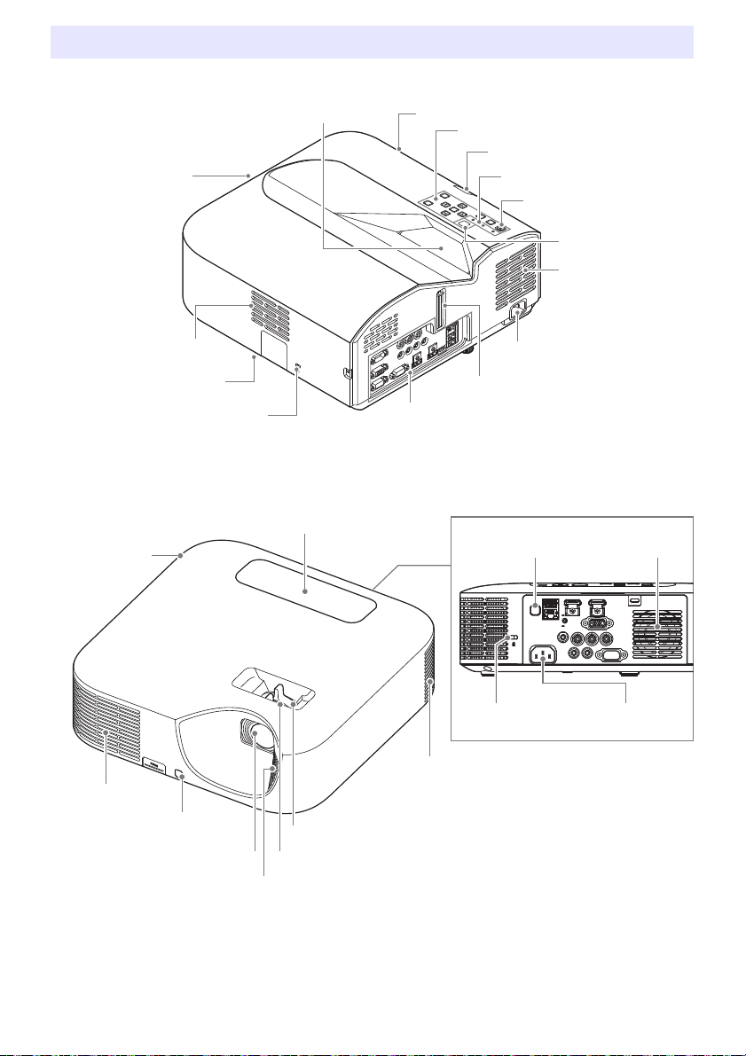
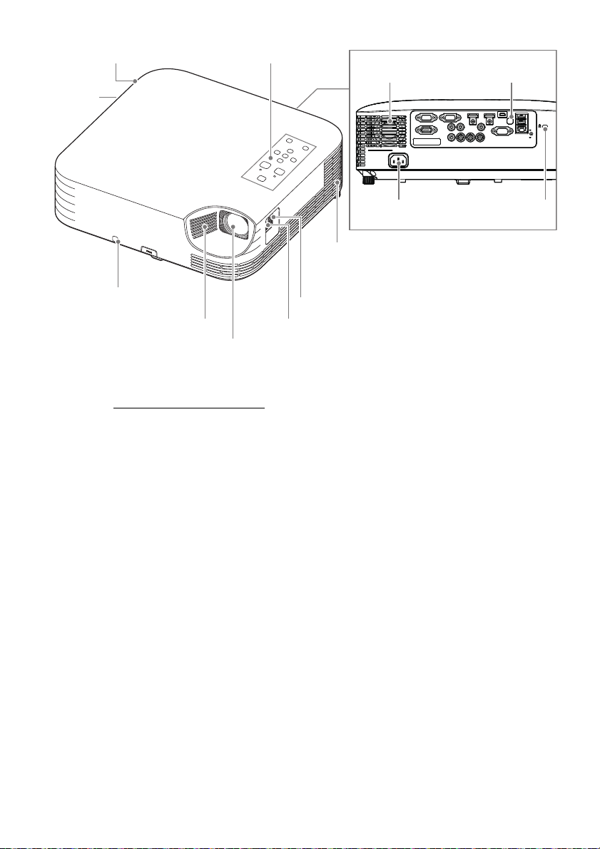
General Guide
Focus lever
AC Terminal
Remote control signal receiver
Terminals
Brightness sensor
[P] key
Indicators
Control panel
Intake vents
Exhaust vents (left side)
Projection lens
Security bar
Security lock hole*
1
Intake vents
Speaker
Key and indicator panel
Remote control signal receiver
Exhaust vents
Exhaust vents
Intake vents
Projection lens
Zoom ring
Intake vents
Focus ring
Remote control signal receiver Speaker
Security lock hole*
1
AC Terminal
XJ-UT Series
XJ-F Series
23
Page 24
XJ-S Series
Key and indicator panel
Remote control signal receiver
Exhaust vents
Intake vents
Intake vents
Zoom ring
Projection lens
Focus ring
Remote control signal receiverSpeaker
Security lock hole*
1
AC Terminal
Security bar
(bottom)
*1 The anti-theft lock hole is provided for connection of an anti-theft chain. Visit the Kensington Lock
Website at https://www.kensington.com/
for more information.
24
Page 25
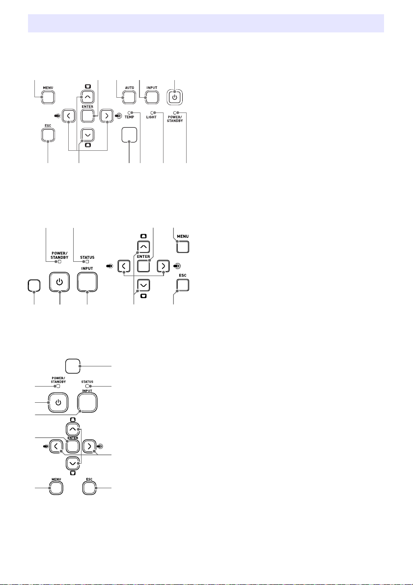
Key and Indicator Panel
(1
(2
(2 (3
XJ-UT Series
XJ-F Series
[MENU] key
[ENTER] key
[AUTO] key (XJ-UT Series)
[INPUT] key
[ON/Stand-by P] key
[ESC] key
Cursor keys (q/w/U/I)
Brightness sensor
TEMP indicator (XJ-UT Series)
LIGHT indicator (XJ-UT Series)
POWER/STANDBY indicator
STATUS indicator (XJ-F Series/XJ-S Series)
XJ-S Series
(2
(3
25
Page 26
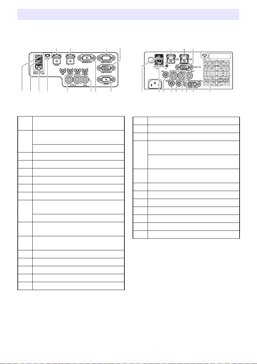
Back Terminals
XJ-UT Series
XJ-F Series
HDMI 2 terminal
(XJ-UT352W / XJ-UT352WN)
HDMI 1 terminal
(XJ-UT352W / XJ-UT352WN)
HDMI terminal (XJ-UT312WN)
COMPUTER IN 1 terminal
COMPUTER IN 2 terminal
MIC terminal
AUDIO OUT terminal
AUDIO IN 1 terminal
AUDIO IN 2 terminal
USB-A/DC 5V port
(XJ-UT312WN / XJ-UT352WN)
DC 5V port (XJ-UT352W)
USB-A port
(XJ-UT312WN / XJ-UT352WN)
LAN terminal
(XJ-UT312WN / XJ-UT352WN)
LOGO terminal
AUDIO IN R/L terminals
VIDEO terminal
MONITOR OUT terminal
SERIAL terminal
(3
(4 (5 (7(6
(2(1
HDMI 2 terminal
HDMI 1 terminal
COMPUTER IN terminal
USB-A/DC 5V port
(XJ-F21XN / XJ-F211WN)
DC 5V port
(XJ-F11X / XJ-F101W)
LAN terminal
(XJ-F21XN / XJ-F211WN)
MIC terminal (XJ-F21XN / XJ-F211WN)
AUDIO OUT terminal
AUDIO IN terminal
AUDIO IN R/L terminals
VIDEO terminal
SERIAL terminal
LOGO terminal
(2 (3
(1
26
Page 27
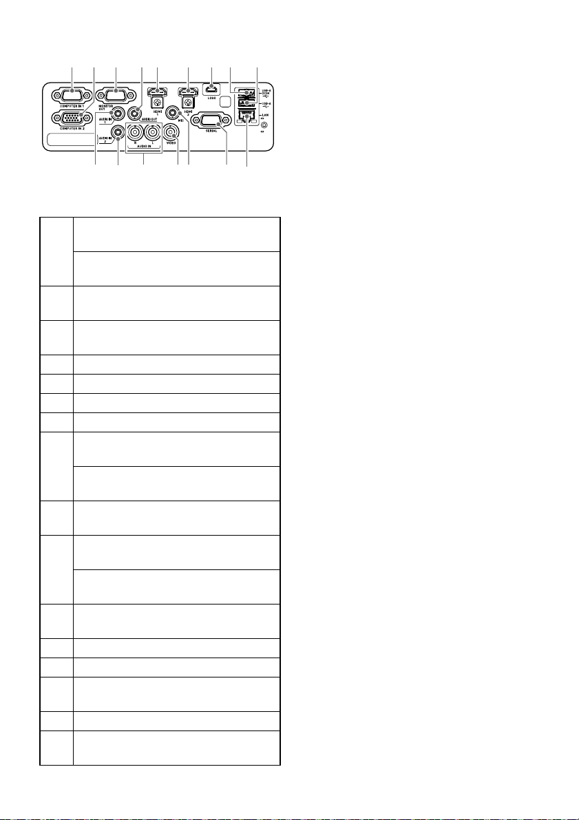
XJ-S Series
(3 (4(5 (6 (7
(1 (2
COMPUTER IN 1 terminal
(XJ-S400UN / XJ-S400WN)
COMPUTER IN terminal
(XJ-S400U / XJ-S400W)
COMPUTER IN 2 terminal
(XJ-S400UN / XJ-S400WN)
MONITOR OUT terminal
(XJ-S400UN / XJ-S400WN)
AUDIO OUT terminal
HDMI 1 terminal
HDMI 2 terminal
LOGO terminal
USB-A/DC 5V port
(XJ-S400UN / XJ-S400WN)
DC 5V port
(XJ-S400U / XJ-S400W)
USB-A port
(XJ-S400UN / XJ-S400WN)
AUDIO IN 1 terminal
(XJ-S400UN / XJ-S400WN)
AUDIO IN terminal
(XJ-S400U / XJ-S400W)
AUDIO IN 2 terminal
(XJ-S400UN / XJ-S400WN)
AUDIO IN R/L terminals
VIDEO terminal
MIC terminal
(XJ-S400UN / XJ-S400WN)
SERIAL terminal
LAN terminal
(XJ-S400UN / XJ-S400WN)
27
Page 28
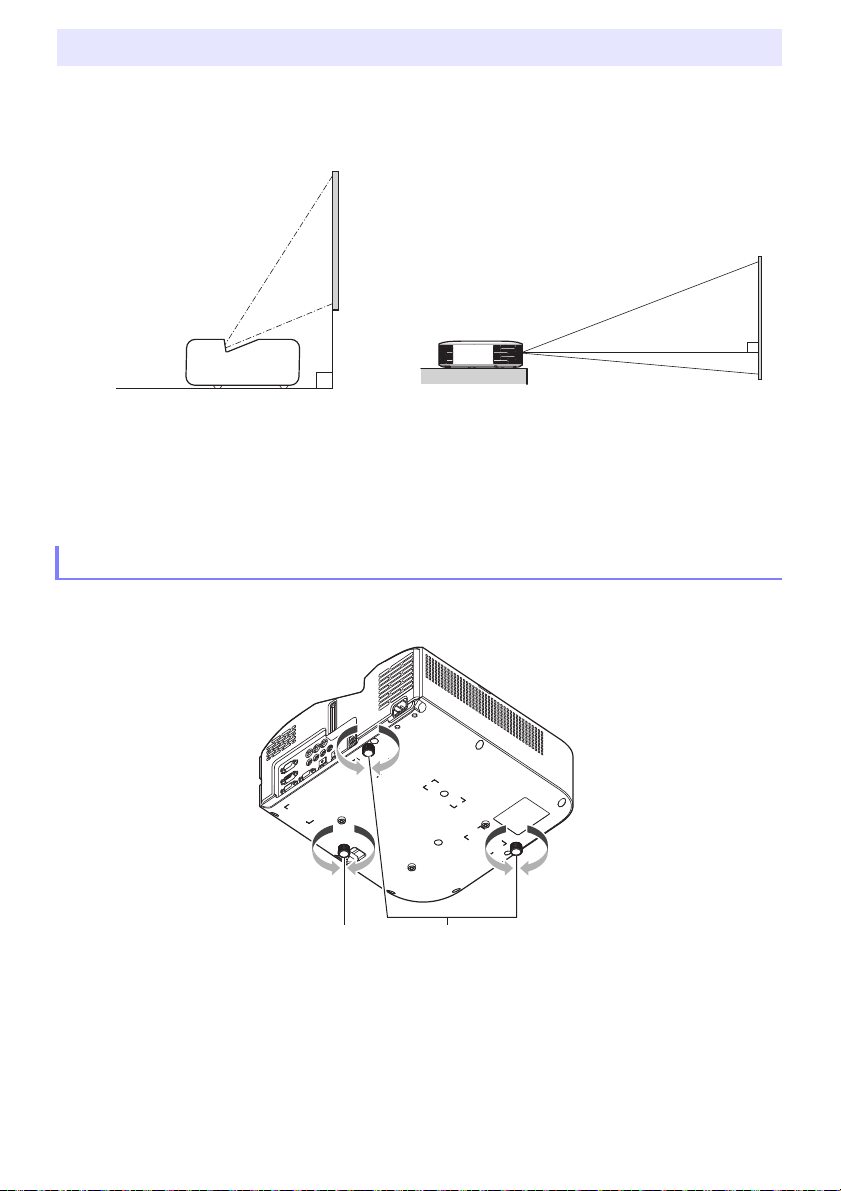
Placing the Projector on a Desk or on the Floor
Screen
Screen
Locate the projector on a desk, table, or stand that is firm and level. Make sure that you allow
sufficient space around the sides and back of the projector for proper ventilation. The illustrations
below show how the projector should be oriented relative to the screen for optimum projection.
XJ-UT Series XJ-F Series/XJ-S Series
Test Pattern
You can project a test pattern when setting up the projector to help determine the proper image size,
projector orientation, etc. For details, see “Test Pattern Projection” on page 55.
Adjusting the Vertical Angle of the Projector
XJ-UT Series
Rotate the single foot on the bottom front of the projector to fine adjust the projector’s vertical
angle.
Rotate the two feet on the bottom back of the projector to fine adjust the projector’s horizontal
angle.
28
Page 29
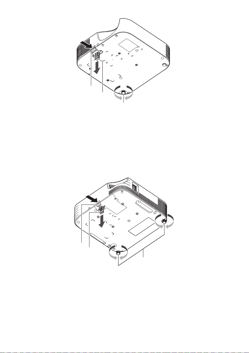
XJ-F Series
Lift up the front of the projector and press the release button. This causes the front foot to drop
from the bottom of the projector.
While holding down the release button, raise and lower the front of the projector. When the front
foot is the height you want, release the release button. The front foot will lock at that position.
Make fine adjustments to the horizontal tilt of the projector by rotating the rear foot. Only one of the
rear feet is adjustable to a height of ±3 mm. The adjustable rear foot has a click position, which
indicates the setting where its height is the same as that of the other rear foot.
XJ-S Series
Lift up the front of the projector and press the release button. This causes the front foot to drop
from the bottom of the projector.
While holding down the release button, raise and lower the front of the projector. When the front
foot is the height you want, release the release button. The front foot will lock at that position.
Make fine adjustments to the horizontal tilt of the projector by rotating the two rear feet.
29
Page 30

Setup Precautions
Use a conveniently located power outlet that you can reach easily when you need to unplug the
projector.
Airflow from air conditioning equipment can blow the heat being exhausted from the area around
the projector’s lens in a way that causes heat ripples to appear in the projected image. If this
happens, adjust the airflow of the air conditioning equipment or move the projector.
XJ-UT Series
Maintain a distance of at least 6 cm (2.4 inches) between the front of the projector (from which light
is being emitted) and the projection surface (screen). Maintain a distance of at least 30 cm
(11.8 inches) between surfaces and the other sides of the projector. There should be no other
objects within the above distances from the projector. Particular care is required to keep objects
away from projector air intake and exhaust openings.
XJ-F Series/XJ-S Series
Do not located any objected within 30 cm (11.8 inches) around the projector. Particular care is
required to keep objects away from projector air intake and exhaust openings.
30
Page 31
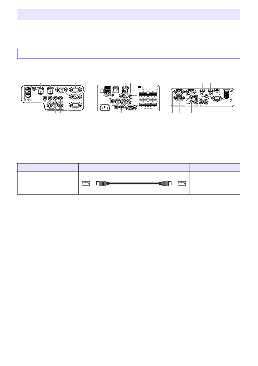
Connecting with Another Device
HDMI cable
HDMI Type A
Before starting projection, you first need to connect a computer, video device, and/or other devices to
the projector. When selecting a cable, make sure that the shapes of its connectors match the shapes
of the terminals on the projector and the devices being connected.
Connecting a Computer
Connect to the HDMI terminal or analog RGB terminal (VGA terminal) of the computer.
XJ-UT Series XJ-F Series XJ-S Series
HDMI Connection
With this type of connection, the video signal and audio signal from a computer are input
simultaneously using a single cable.
Projector Terminal Connection Cable Computer Terminal
HDMI 2
HDMI 1*
or
1
HDMI Out terminal
*1 An XJ-UT312WN model has an HDMI terminal only.
31
Page 32

Analog RGB Connection
Note
RGB cable (D-Sub 15-pin cable)
15-pin Mini D-Sub
Audio cable
Stereo mini jack
HDMI cable
HDMI Type A
With this type of connection, the RGB cable inputs only the image signal of the computer. If you also
want to output audio from the computer, you will need to connect an audio cable.
Projector Terminal Connection Cable Computer Terminal
COMPUTER IN 1*2
or
COMPUTER IN 2
AUDIO IN 1*3
or
AUDIO IN 2
*2 An XJ-F Series model, XJ-S400U, or XJ-S400W has a COMPUTER IN terminal only.
*3 An XJ-F Series model, XJ-S400U, or XJ-S400W has an AUDIO IN terminal only.
An XJ-UT Series model, XJ-S400UN, or XJ-S400WN has a MONITOR OUT terminal that
lets you directly output the signal being input to the
COMPUTER IN 2 terminal to an external display. For details, see “Using the MONITOR OUT
Terminal (XJ-UT Series, XJ-S400UN, XJ-S400WN)” (page 78).
The relationship between the image output terminal and audio output terminal can be
changed as required. Note that the combinations shown in the table are initial default settings.
For details, see “Relationship Between Image Input and Audio Input” (page 45).
COMPUTER IN 1 terminal or
Analog RGB Out (VGA)
terminal
Headphones jack or
other audio output jack.
Connecting to a Video Device
With this type of connection, connect to the HDMI, component video, or composite video terminal of
the video device.
XJ-UT Series XJ-F Series XJ-S Series
HDMI Connection
With this type of connection, the video signal and audio signal from the video device are input
simultaneously using a single cable.
Projector Terminal Connection Cable Video Device Terminal
HDMI 2
or
1
HDMI 1*
*1 An XJ-UT312WN model has an HDMI terminal only.
32
HDMI Out terminal
Page 33

Component Video Connection
Note
Component video cable
15-pin Mini D-Sub
Audio cable
Stereo mini jack
RCA audio video cable
RCA jacks
Video device component video output terminals are grouped as a set of three: Y, Cb, Cr or Y, Pb, Pr.
Connect the component video cable so the colors of its three plugs match the colors of the terminals
(green for Y, blue for Cb or Pb, red for Cr or Pr). If you want to output the audio of the video device
through the projector’s speaker, you also will need to connect an audio cable.
Projector Terminal Connection Cable Video Device Terminal
COMPUTER IN 1*2
or
COMPUTER IN 2
AUDIO IN 1*3
or
AUDIO IN 2
Component Video Out
terminals
Audio Out terminals
*2 An XJ-F Series model, XJ-S400U, or XJ-S400W has a COMPUTER IN terminal only.
*3 An XJ-F Series model, XJ-S400U, or XJ-S400W has an AUDIO IN terminal only.
Composite Video Connection
Video device composite video output terminals are grouped as a set of three: video (yellow) and audio
(white and red). Use a video and audio RCA cable to connect to the like-colored terminals of the
projector.
Projector Terminal Connection Cable Video Device Terminal
VIDEO,
AUDIO IN R/L
Composite Video Out/
Audio Out terminals
The relationship between the image output terminal and audio output terminal can be
changed as required. Note that the combinations shown in the table are initial default settings.
For details, see “Relationship Between Image Input and Audio Input” (page 45).
33
Page 34

Note
Outputting Audio from the Projector to Another Device
AUDIO OUT terminal
AUDIO OUT terminal
AUDIO OUT terminal
Audio cable
Stereo mini jack
You can output audio to an amp speaker or another device instead of using the projector’s built-in
speaker.
XJ-UT Series XJ-F Series XJ-S Series
Under initial projector default settings, audio is output from the projector’s built-in speaker. To output
audio using another device, connect as shown below and then change the Setup Menu “Option
Settings 2 3 Audio Out” setting to “Line”.
Projector Terminal Connection Cable Other Device Terminal
AUDIO OUT Audio In terminal
You can also configure settings so that audio input to the projector continues to be output
from the AUDIO OUT terminal even while the projector is in standby (projector turned off, but
being supplied with power) (An XJ-UT Series model, XJ-S400UN, or XJ-S400WN only). See
“Option Settings 2 3 Standby RGB/Audio” (page 65).
34
Page 35

Connecting a Microphone (XJ-UT Series, XJ-F21XN, XJ-F211WN,
MIC terminal
MIC terminal
MIC terminal
MIC terminal
Mini jack
LAN terminal
LAN terminal
LAN terminal
LAN cable
RJ-45 RJ-45
XJ-S400UN, XJ-S400WN)
Connecting a microphone to the projector’s MIC terminal makes it possible to output microphone
input through the projector’s speaker.
XJ-UT Series XJ-F21XN, XJ-F211WN XJ-S400UN, XJ-S400WN
Use this terminal to connect a dynamic microphone.
Plug-in power type microphones are not supported.
Connecting to a Network with a LAN Cable (Network Models Only)
If you have a network model projector, you can use a LAN cable to connect it to the network hub or
another device of an existing network. Use a 100BASE-TX or 10BASE-T standard Category 5 or higher
LAN cable for connection. Use of a shielded (STP) cable is recommended.
XJ-UT312WN, XJ-UT352WN XJ-F21XN, XJ-F211WN XJ-S400UN, XJ-S400WN
Projector Terminal Connection Cable Other Device Terminal
LAN LAN terminal (RJ-45)
After connecting the projector to a network, you will be able to project the screen of any computer on
the network. You also will be able to control the projector and configure its settings from a computer.
For details, see the separate “Network Function Guide”.
35
Page 36

Connecting a Wireless Adapter (Network Models Only)
LOGO terminal
LOGO terminal
LOGO terminal
USB cable
USB Micro B
Connecting the projector’s wireless adapter* enables wireless connection to a computer or a smart
device, or to an existing wireless access point.
* The YW-41 wireless adapter may have been provided with your projector or may be available
separately. See “Unpacking” (page 21).
XJ-UT312WN, XJ-UT352WN XJ-F21XN, XJ-F211WN XJ-S400UN, XJ-S400WN
XJ-UT312WN, XJ-UT352WN, XJ-S400UN, XJ-S400WN
Plug into the
* If you have an XJ-S Series projector whose wireless adapter is covered
(page 38), connect the adapter to the
XJ-F21XN, XJ-F211WN
Plug into the
For details about operations to use for wireless connection of the projector to a computer or a wireless
access point, and about operations after a connection is established, refer to the separate “Network
Function Guide”.
USB-A/DC 5V port or the USB-A port.*
USB-A port.
USB-A/DC 5V port.
LOGO Terminal (Firmware Updates, User Logo Transfers)
You can update the projector’s firmware (software in the projector’s flash ROM) using a computer
connected to the projector’s LOGO terminal. You can also transfer user logo images from the
computer to the projector.
XJ-UT Series XJ-F Series XJ-S Series
Projector Terminal Connection Cable Computer Terminal
LOGO USB port
For information about operations after connection, refer to the documentation below, which is
available from the CASIO website.
Firmware updates :Projector Firmware Update Guide
User logo transfers: User Logo Transfer Guide
36
Page 37

Connecting a Scientific Calculator (Network Models Only)
USB cable
USB Type A Type B mini
SERIAL terminal
SERIAL terminal
SERIAL terminal
Serial cable (cross)
D-Sub9 pin
After connecting a scientific calculator to the projector, you will be able to project the calculator’s
screen image. For information about connectable calculators, go to the CASIO website.
XJ-UT312WN, XJ-UT352WN XJ-F21XN, XJ-F211WN XJ-S400UN, XJ-S400WN
Projector Terminal Connection Cable Calculator Terminal
USB-A/DC 5V
or
USB-A
USB port
Important!
To project the screen image of a scientific calculator, select “CASIO USB Tool” as the
projector’s input source. For information about how to do this, see “Changing the Input
Source Manually” (page 45).
If you experience problems after connecting a scientific calculator to the projector, disconnect
the USB cable from both devices. Next, use the cable to re-connect them.
For information about scientific calculator operation, refer to its user documentation.
SERIAL Terminal (Projector Control Using Commands)
You can control the projector by sending it commands from a device (computer, other RS-232C
controller device) connected to the projector’s SERIAL terminal.
XJ-UT Series XJ-F Series XJ-S Series
Projector Terminal Connection Cable Other Device Terminal
SERIAL RS-232C terminal
For details about control commands, see “Projector RS-232C Control” (page 85).
37
Page 38

USB Power
Wireless adapter cover
Screw
Wireless adapter cover
Screw
The wireless adapter can be connected
to the lower USB-A port only.
You can use the projector to supply USB power to another device. See “Supplying USB Power to
Another Device” (page 76).
Cover Included with the YW-41 Wireless Adapter
The YW-41* wireless adapter comes with an anti-theft cover that can be installed on an XJ-F Series or
XJ-S Series model.
* The YW-41 wireless adapter may have been provided with your projector or may be available
separately. See “Unpacking” (page 21).
Keep the wireless adapter and the wireless adapter cover out of the reach of
*
Caution
XJ-F Series/XJ-S Series
After plugging the wireless adapter into the projector, install the wireless adapter cover as required.
Cover the wireless adapter with the wireless adapter cover and then secure it with the screw.
small children. Accidental swallowing of the adapter can interfere with proper
breathing and create a life-threatening situation.
XJ-F Series XJ-S Series
XJ-UT Series
The cover that comes with the wireless adapter cannot be installed on an XJ-UT Series model. To
protect against theft of the wireless adapter while it is connected to the projector, use the cable cover
(page 39) that comes with the projector.
38
Page 39
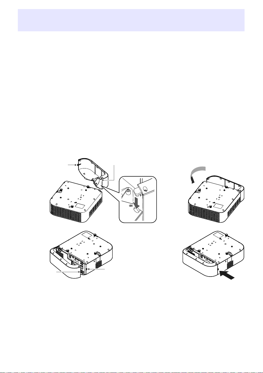
Attaching and Removing the Cable Cover
Figure 1 Figure 2
Figure 3 Figure 4
Screw
Hook
Screw
Screw hole
(XJ-UT Series)
Before attaching or removing the cable cover, turn off the projector and unplug its power plug from the
power outlet. After turning off the projector, wait for a while to allow it to cool.
To attach the cable cover
1.
Turn the projector over and insert
the cable cover hook into the hole
provided on the projector (Figure 1).
2.
Rotate the cable cover in the
direction indicated by the arrow in
Figure 2 to attach it to the projector.
3.
Aligning the cable cover screw with
the screw hole on the projector
(Figure 3), use a Phillips head screw
driver to tighten the screw (Figure 4).
To remove the cable cover
1.
Use a Phillips head screw driver to
loosen the cable cover screw until it
disengages from the projector
(without detaching it from the
cover).
2.
Remove the screw side of the cable
cover from the projector and then
unhook the cover hook from the
projector.
39
Page 40

Note
Remote Controller
Projector operations are performed using the remote controller that comes with it. Point the remote
controller signal emitter at one of the signal receivers on the projector as you perform remote
controller key operations. The maximum range of the remote controller signal is approximately
5 meters (16.4 feet) (between signal emitter and receiver).
Remote control signal emitter
Turns power on or off.
Press to exit the currently displayed menu or to cancel an
operation.
Keys used when configuring the remote ID setting (page 56)
and when performing countdown timer operations (page 56).
Use the cursor keys ([][][][]) to move between menu
items, and to change setting values. Press the [ENTER] key to
select a menu item or to execute a function.
Press each of these keys to execute their functions. For
information about the function of each key, see “Operating the
Projector” (page 41).
Important!
To avoid running down the batteries, store the remote control unit so its keys are not pressed
inadvertently.
Specifications are subject to change without notice.
40
Page 41

Operating the Projector
Note
Unless specifically noted otherwise, the operations in this section are performed using the remote
controller. If both the projector and the remote controller have the same key, either one can be used to
perform the corresponding operation.
Turning the Projector On or Off
This section explains how to turn projector power on and off, and provides information about powerrelated settings.
For information about the general procedure that is required before turning on the projector, see
“Operation Flow to Projection” (page 21).
To turn on the projector
1.
Connect the provided power cord to the projector’s AC terminal and plug in to a
power outlet.
Wait until the POWER/STANDBY indicator lights red.
2.
Press the [P] key to turn on the projector.
This will cause the POWER/STANDBY indicator (green) to flash for a few seconds, and then
stop flashing and remain lit.
The projector will perform an auto input search operation at this time. If it finds an input signal,
it will start projecting its image. For details, see “Using Auto Input Search” (page 43).
For details about what indicators show, see “Normal Operation Indicators” (page 70).
To turn off the projector
1.
Press the [P] key.
This will cause the POWER/STANDBY indicator (red) to flash for a few seconds, and then stop
flashing and remain lit.
2.
Unplug the power cord from the power outlet and then disconnect it from the
projector.
Direct Power On
When “On” is selected for the “Option Settings 1 3 Direct Power On” setting (page 64), the projector
will turn on automatically whenever you plug its power cord into a power outlet. (Initial default setting:
“Off”).
41
Page 42

Auto Power Off
Under initial default settings, Auto Power Off is enabled and will automatically turn off the projector
after about 10 minutes of non-operation (no key operation or input signal). You can use “Option
Settings 1 3 Auto Power Off” (page 64) to change the Auto Power Off trigger time or to disable Auto
Power Off.
Auto Projection Off
Auto Projection Off automatically turns off the projection light whenever the input signal from an input
source is lost during projection. The light will turn back on if the input signal from the original input
source is restored within 20 minutes after the light is turned off. This function comes in handy when
multiple computers are alternately connect to the projector.
For details, see “Using Auto Projection Off” (page 47).
Selecting an Input Source (INPUT)
Your projector can project images from input sources described below.
Input Source Description
Computer (1/2)*
Video Projects the composite video signal of a video device connected to the projector’s
HDMI (1/2)*
CASIO USB Tool*
Network*
Templates Projects the image of one of the projector’s built-in templates*
1
1
2
2
Projects the RGB signal of a computer or the component video signal of a video
device connected to a projector COMPUTER IN (1/2) terminal.*
VIDEO terminal.
Projects the HDMI(PC) signal of a computer or HDMI(DTV) of a video device
connected to a projector HDMI(1/2) terminal.*
Projects the screen image of a scientific calculator (page 37).
Projects the image a computer connected to the projector over a network. For details,
see the separate “Network Function Guide”.
1
1
3
(page 53).
*1 The number of inputs (input terminals) depends on your projector model.
*2Network models only
*3 With a network model, you can add template images. For details, see the separate “Network
Function Guide”.
Resolution
Depending on the projector model, its projection resolution will be fixed at XGA (1024 × 768 pixels),
WXGA (1280 × 800 pixels), or WUXGA (1920 × 1200 pixels). Images may appear coarse, text and other
figures may be difficult to read or a moire pattern may appear when the input signal from a computer
does not match the projector’s projection resolution. If this happens, try doing the following.
Change the computer’s output resolution setting so it matches the projector’s projection resolution.
For information about the projection resolution of your projector, see “Specifications” (page 88).
See the user documentation that comes with your computer for details about changing its settings.
Change the “Aspect Ratio” setting to “True” (Applies only to models that support WXGA or WUXGA
projection resolution). With the “True” setting, the projector projects the input signal at its actual
size (1 input source dot equal to one projector output pixel dot). For information about configuring
the Aspect Ratio setting, see “Change the aspect ratio of the projected image (ASPECT)” (page 50).
42
Page 43

Note
Note
Using Auto Input Search
After the projector is turned on, it starts an auto input search operation. It sequentially checks its
image input terminals and, when it finds an input signal, it automatically starts projection of the
signal’s image.
Auto input search is not performed if “Test Pattern” is selected for “Screen Settings 3 No
Signal Screen” (page 62).
To trigger an auto input search operation manually
1.
Hold down the [INPUT] key until the message “Searching...” appears on the
display.
While an auto input search operation is in progress, the name of the input source the projector
is currently checking along with the message “Searching...” will be shown on the display.
When an input signal is detected, the auto input search operation stops, the “Searching...”
message disappears, and the input signal’s image starts to be projected. To trigger an auto
input search operation manually, hold down the [INPUT] key until the “Searching...” message
appears on the display.
To stop an ongoing auto input search operation, press the [INPUT] or [ESC] key.
If the projector is unable to detect an input signal it repeats the detect operation a second time
in the sequence shown under “Auto Input Search Sequence” (page 44). If the projector is
ultimately unable to detect an input signal, the message “No signal input” will appear.
Auto Input Search Following Power On
When the projector is turned on, it will perform an auto input search operation when either of the
conditions described below exists.
When the input source being projected the last time the projector was turned off was CASIO USB
Tool, Network, or Templates.
When the input source being projected the last time the projector was turned off was not one of
those above and there is no input signal from the last projected input source. If there is an input
signal from the last input source, projection of that input source will resume.
The following input sources are not detected immediate after the projector is turned on:
CASIO USB Tool, Network, Templates.
43
Page 44

Auto Input Search Sequence
Note
Computer1 Computer2 Video HDMI1 HDMI2
Computer1 Computer2 Video HDMI1 HDMI2
Templates Network CASIO USB Tool
Computer1 Computer2 Video HDMI
Templates Network CASIO USB Tool
Computer Video HDMI1 HDMI2
Computer Video HDMI1 HDMI2
Templates Network CASIO USB Tool
Auto input search is performed in a particular sequence, depending on the projector model.
■ XJ-UT352W
■ XJ-UT352WN, XJ-S400UN, XJ-S400WN
■ XJ-UT312WN
■ XJ-F11X, XJ-F101W, XJ-S400U, XJ-S400W
■ XJ-F21XN, XJ-F211WN
When the projector is turned on, it automatically performs an auto input search operation
starting from the input source that was selected when power was last turned off.
You can configure settings to control whether or not an auto input search operation is trigged
by turning on the projector or by holding down the [INPUT] key. See “Input Settings 3 Auto
Input Search” (page 63).
44
Page 45

Changing the Input Source Manually
Use the procedure below to change the input source manually.
1.
Press the [INPUT] key to display the input menu.
2.
Use the [INPUT], [], and [] keys to select the name of the input source you
want, and then press the [ENTER] key.
Note that even if you do not press the [ENTER] key, the projector will automatically switch to
the input source you selected after about three seconds.
The name of the input source you selected will appear in the upper right corner of the
projection screen for a few seconds.
The message “No signal input” will appear if an input source cannot be found.
Relationship Between Image Input and Audio Input
Selecting an input source causes the projector to output the image from the image input terminal that
corresponds to the input source, and the audio from the audio input terminal. The relationship
between input sources and terminals is shown in the table below.
Input Source Image Input Terminal (Fixed) Audio Input Terminal (Initial Default)
1
Computer (1/2)*
Video VIDEO AUDIO IN R/L
HDMI (1/2)*
CASIO USB Tool*2USB-A (1/2)*
Network*
Templates (Projects a projector built-in image.) AUDIO IN 1 (May be AUDIO IN, depending on the
1
2
COMPUTER IN (1/2)*
HDMI (1/2)*
USB-A (1/2)*1*3 or LAN USB-A (1/2)*1*3 or LAN (Network AUDIO)
1
1
1
AUDIO IN (1/2)*
HDMI (1/2)*
AUDIO IN 1 (May be AUDIO IN, depending on the
model.)
model.)
1
1
*1 The number of inputs (input terminals) depends on your projector model.
*2 Network models only
*3 YW-41 wireless adapter connection is required. See “Connecting a Wireless Adapter” (page 36).
45
Page 46

Changing the Audio Input
Though the image input terminal of each input source is fixed, audio input terminal assignments can
be changed by you as desired.
To do this: Perform this operation:
Change the audio input for a
particular input source
Return audio inputs for all the
input sources to their initial
default settings
1. Press the [MENU] key to display the Setup Menu.
2. Select the following in sequence, and then press the [ENTER] key: “Option
Settings 2”, “Audio Input”.
3. Use the [] and [] keys to select the input source whose audio input setting
you want to change.
4. Use the [] and [] keys to select the audio input you want to assign to the
selected input source.
5. Repeat steps 3 and 4 as required.
6. After the settings are the way you want, press the [MENU] key to exit the Setup
Menu.
On the Setup Menu, perform the following operation: “Option Settings 2”, “Initialize
Projector Options 2”.
Note that this returns all items included on the “Option Settings 2” menu (not
just audio input settings) to their initial default settings.
46
Page 47

Using Auto Projection Off
Cable unplugged.
Cable plugged in.
User 1
User 2
POWER/STANDBY
flashes green.
Light turns off after about 10 seconds.
POWER/STANDBY
lights green.
Projection resumes automatically.
Auto Projection Off automatically turns off the projection light approximately 10 seconds*1 after the
input signal from an input source is lost during projection. The light will turn back on if the input signal
from the original input source is restored within 20 minutes*
*1 A message first appears about five seconds after the input signal is lost, and then the light is turned
off five seconds after that.
*2 The projector automatically turns off if the input source is not restored within 20 minutes.
Auto Projection Off Operation Example
The example below shows an image of how Auto Projection Off works when multiple users alternately
connect to the projector.
2
after the light is turned off.
Though the above example shows a cable connection, the same also applies to wireless LAN
connection.
47
Page 48

Enabling and Disabling Auto Projection Off
Auto Projection Off is disabled under initial projector default settings. To enable Auto Projection Off,
change “Screen Settings 3 Auto Projection Off” (page 62) on the Setup Menu to “Enable”.
Auto Projection Off Projection Light Control
Projection Light Off Conditions
If the image input signal from the input source device to the projector is lost for some reason while
projection is being performed, the no signal screen (page 62) or the network standby screen* appears
first. If no operation is performed for about 10 seconds, the projection light turns off and audio
becomes muted.
The following message will be displayed for about five seconds before the light turns off: “Auto
Projection Off is enabled. The projector will stop projecting.”
Auto Projection Off operation is not affected by whether audio is being input.
* The network standby screen appears when the source setting is “Network”. It indicates that the
projector is standing by for a network connection (wired LAN or wireless LAN). For details about
projection using a network connection, refer to the separate “Network Function Guide”.
Regardless of the current Auto Projection Off setting, Auto Projection Off is not triggered while any
one of the following conditions exists.
If there has been no projection from any input source since the projector was turned on.
While a template (page 53), the countdown timer (page 56), or a test pattern (page 55) is being
projected.
While an auto input search operation is in progress (page 43).
Projection Light Restoration Conditions
The projection light will turn back on when the currently selected input source resumes signal input
(or, in the case of the “Network” input source, a network connection starts projection), or when a key
operation is performed on the projector or its remote controller.
Auto Power Off Following Projection Light Off
If the “Auto Projection Off” setting is “Enable”, the Auto Power Off trigger time is fixed at 20 minutes
after the projection light is turned off. This is true regardless of the current Auto Power Off setting
(page 64).
Projector Operation While the Projection Light is Off
The POWER/STANDBY indicator (green) flashes slowly while the projection light is turned off by the
Projection Light Off function.
Auto Power Off will be triggered if no projector key operation is performed for approximately 20
minutes after the projection light turns off.
48
Page 49

Basic Image and Audio Operations During Projection
Note
To end the operations below, press the [ESC] key.
To do this: Perform this operation:
■ XJ-UT Series
Correct vertical and
horizontal keystoning
manually (KEYSTONE)
■ XJ-F Series,
XJ-S Series
Correct vertical keystoning
manually (KEYSTONE)
Zoom an image (D-ZOOM) 1. Press the [D-ZOOM +] key to enlarge at the center of the projected image.
Momentarily blank the
image and mute the audio
(BLANK)
Freeze an image (FREEZE) 1. Press the [FREEZE] key.
Auto adjust an image
(AUTO)
1. While there is no menu or dialog box displayed on the projection screen, press the
projector [] or [] key, or the remote controller [KEYSTONE +] or [KEYSTONE –]
key.
2. Use the [] and [] keys to correct vertical keystoning, and the [] and [] keys to
correct horizontal keystoning.
Both vertical and horizontal keystoning can be corrected within a range of ±5°.
Using Projector Keys
1. After confirming that a menu or dialog box is not on the projection screen, press
the projector’s [] or [] key.
2. Use the [] and [] keys to correct vertical keystoning.
Using Remote Controller Keys
1. Use the [KEYSTONE +] and [KEYSTONE –] keys to correct vertical keystoning.
You can correct this image within a range of ±30°.
If “On” is selected for “Option Settings 1 3 Auto Keystone Correction”
(page 63), the projector will detect its vertical tilt and perform keystone
correction automatically.
2. To zoom in on the center of the projected image more, press the [D-ZOOM +] key
again. To zoom out, press the [D-ZOOM –] key.
3. While an image is zoomed, use the [], [], [], and [] keys to scroll the view to
other parts of the image.
1. Press the [BLANK] key.
This cuts off the image and audio from the input source, and projects the screen
specified by the Setup Menu “Screen Settings 3 Blank Screen” setting (page
62). If “Projection Off” is specified for the “Blank Screen” setting, the projection
light will turn off at this time.
2. To restore the image and audio, press the [BLANK], [ESC], or [P] key.
Note that the [P] key can be used only when “Projection Off” is selected for the
“Blank Screen” setting.
This freezes the current input source image.
2. To return to the real-time input source image, press the [FREEZE] key again or
press the [ESC] key.
1. Press the [AUTO] key.
This automatically adjusts the frequency and phase in accordance with the input
signal, which can reduce flickering and other projected image problems. This
operation is supported while the input source is Computer (RGB).
49
Page 50

To do this: Perform this operation:
WXGA models
WUXGA models
“Normal” 3 “Full” 3 “16:9” 3 “4:3” 3 “True”
XGA models “Normal” 3 “Full” 3 “16:9” 3 “16:10”
WXGA models
WUXGA models
“Normal” 3 “16:9” 3 “16:10” 3 “4:3” 3 “Letter Box”
XGA models “Normal” 3 “16:9” 3 “16:10” 3 “4:3”
Change the aspect ratio of
the projected image
(ASPECT)
1. Press the [ASPECT] key.
Each press of the [ASPECT] key cycles between the aspect ratio settings as
shown below. For the meaning of each setting, see “Aspect Ratio Setting
Details” (page 51).
Input source: RGB, HDMI(PC), CASIO USB Tool, Network or Templates
Input source: Video, Component or HDMI(DTV)
Important!
Note that enlarging or reducing the size of an image using the [ASPECT] key
for commercial purposes or public presentation may infringe on the legally
protected copyright of the copyright holder of the original material.
Change the color mode
(FUNC)
Adjust the volume level
(VOLUME)
Mute the audio (VOLUME) 1. Press the [VOLUME +] or [VOLUME –] key to display the “Volume” dialog box.
1. Press the [FUNC] key. On the menu that appears, select “Color Mode” and then
press the [ENTER] key.
2. Use the [] and [] keys to move the highlighting to the color mode you want to
select, and then press the [ENTER] key.
For details on what each color mode does, see “Image Adjustment 1 3 Color
Mode” (page 60).
The color mode cannot be selected when “Off” is selected for the “Light
Control” setting (page 52).
1. Press the [VOLUME +] or [VOLUME –] key to display the “Volume” dialog box.
2. Press the [VOLUME +] key to increase the volume, or the [VOLUME –] key to lower
the volume.
2. Press the [ENTER] key to mute the audio.
3. To restore the audio, press the [VOLUME +] or [VOLUME –] key.
50
Page 51

Aspect Ratio Setting Details
Note
Normal Projects at the projector’s maximum possible size while maintaining the input signal aspect ratio.
Full Projects at the projector’s maximum possible size by enlarging or reducing the input signal.
16:9 This setting specifies a 16:9 aspect ratio, which is the same as a movie screen, high-definition TV, etc.
16:10 This setting specifies a 16:10 aspect ratio. Use this setting to adjust the image for projection onto a
4:3 Regardless of the input signal aspect ratio, the image is always resized to an aspect ratio of 4:3 for
True Projects each input source dot as a projector output pixel dot. If the input signal resolution exceeds
Letter Box With a WXGA model, this will resize the image horizontally to 1280 dots and project 800 vertical dots
For details about how the aspect ratio setting affects the projected image, see “Aspect Ratio Setting
and Projection Image” (page 82).
Using this setting when the input signal is a 16:9 image that has been squeezed to a 4:3 image causes
the image to be displayed with its normal 16:9 aspect ratio.
16:10 aspect ratio screen.
projection.
the projector’s output resolution, the excess is cut off. When projecting while “True” is selected as the
aspect ratio setting for an RGB signal with a resolution that is less than SVGA, the image is enlarged to
SVGA and projected.
of the center of the image, maintaining the aspect ratio of the input signal.
With a WUXGA model, this will resize the image horizontally to 1920 dots and project 1200 vertical
dots of the center of the image, maintaining the aspect ratio of the input signal.
Flipping the Projected Image Horizontally (Mirror Mode)
You can use the procedure below to enter the Mirror Mode, which flips the projected image
horizontally.
1.
While projection from an input source is being performed, press the [INPUT] key.
This displays the input menu. The input source that is currently being projected will be
selected on the menu.
2.
Press the [] or [] key to enter the Mirror Mode.
This exits the input menu and flips the image.
A Mirror Mode icon will be in the upper right corner of the projection screen while the projector
is in the Mirror Mode.
3.
To exit the Mirror Mode, press the [ESC] key.
Pressing any key other than [BLANK], [FREEZE], [D-ZOOM +], [D-ZOOM –], [VOLUME +], or
[VOLUME –] will also exit the Mirror Mode.
Operation of the keys below is enabled while in the Mirror Mode.
[P], [BLANK], [FREEZE], [D-ZOOM +], [D-ZOOM –], [VOLUME +], [VOLUME –]
The [VOLUME +] and [VOLUME –] keys can be used to adjust the volume level, but not to
mute the audio.
51
Page 52

Note
Light Control
Light Control lets you adjust the light being output (light source brightness) by the projector. When
“On” is selected for “Option Settings 1 3 Light Control 3 Light Control” (page 64) on the Setup
Menu (initial default setting), light output can be adjusted to one of seven levels.
To do this: Perform this operation:
Adjust light output 1. While there is no menu or dialog box displayed on the projection screen, press the
Have light output adjusted
automatically
Light Control Off Mode (Maximum Brightness)
If you want the projection light to be at maximum brightness, change “Option Settings 1 3 Light
Control 3 Light Control” (page 64) on the Setup Menu to “Off”, and “Light Control Off Mode” (page
60) to “Bright”.
Selecting “Off” for “Light Control” disables light output adjustment and the brightness sensor.
[] or [] key.
This displays the current light output level as a value from 1 to 7.
2. Use the [] and [] key to adjust light output.
3. To end the operation, press the [ESC] key.
1. Press the [MENU] key to display the Setup Menu.
2. Perform the following menu operation: “Option Settings 1”, “Light Control”, “Light
Sensor”.
3. Use the [] and [] keys to change “Light Sensor” to “On”.
4. After the settings are the way you want, press the [MENU] key to exit the Setup
Menu.
52
Page 53

Digital Screen Shift
You can use the procedures in this section to reduce the size of the projected image while maintaining
its aspect ratio and to shift the projection image vertically or horizontally, without physically moving
the projector.
To do this: Perform this operation:
Adjust the projection
image size and position
Return the projection
image size and position to
their initial defaults
1. Press the [MENU] key to display the setup menu.
2. Select the following in sequence, and then press the [ENTER] key: “Screen
Settings”, “Digital Screen Shift”, “Reposition Digital Screen Shift”.
This displays the “Digital Screen Shift” dialog box.
3. Use the [D-ZOOM –] and [D-ZOOM +] keys to adjust the size of the projected
image within the range of 84% to 100%.
If a zoom factor that is less than 100% is specified, you can also perform the
step 4 and 5 below to reposition the projection image. If 100% is specified, jump
to step 5 of this procedure.
4. Use the [] and [] keys to move the projection image vertically, and the [] and
[] keys to move it horizontally.
5. When everything is the way you want, press the [ESC] key to close the dialog box.
Next press [MENU] to close the setup menu.
1. Press the [MENU] key to display the setup menu.
2. Select the following in sequence, and then press the [ENTER] key: “Screen
Settings”, “Digital Screen Shift”, “Restore Default Digital Screen Shift”.
3. Press the [] key, select “Yes”, and then press the [ENTER] key.
Projecting a Template
Your projector comes with nine built-in templates that let you project horizontal lines, gridlines, and
other images onto a whiteboard or blackboard.
With a network model, you can increase the number of available templates by transferring template
images from a computer to projector memory. For details, see the separate “Network Function
Guide”.
To project a template
1.
Press the [INPUT] key to display the input menu.
2.
Use the [INPUT], [], and [] keys to select “Templates”, and then press the
[ENTER] key.
This projects the template that was previously last projected.
3.
Use the [] and [] keys to change to another template type.
Use the procedure under “To change the template type (XJ-UT352W, XJ-F11X, XJ-F101W,
XJ-S400U, XJ-S400W)” (page 54) or “To change the template type (Network Models)” (page
54) to change to another template.
With a network model, you can also adjust projection brightness (page 60).
53
Page 54

4.
Note
Note
To stop template projection, change to another input source or turn off the
projector.
Note that an image input signal being input to the projector cannot be projected while a
template is being projected.
Auto Projection Off (page 47) and Auto Power Off (page 64) are both disabled while a template
is being projected.
With an XJ-UT352W, XJ-F11X, XJ-F101W, XJ-S400U, and XJ-S400W model, the following
settings cannot be adjusted while a template is being projected: “Brightness” (page 60),
“Contrast” (page 60).
To change the template type (XJ-UT352W, XJ-F11X, XJ-F101W,
XJ-S400U, XJ-S400W)
1.
While a template is being projected, press the [FUNC] key and then the [ENTER]
key.
This displays the “Template Type” menu.
2.
Use the [] and [] keys to select the template you want to project, and then
press the [ENTER] key.
To change the template type (Network Models)
1.
While a template is being projected, press the [FUNC] key and then the [ENTER]
key.
This displays the template selection screen.
2.
Use the cursor keys to move the focus to the template you want to project.
To project a template that is located in a folder that is different from the currently displayed
folder, perform the steps below.
(1) While the focus is located at the upper left template, press the [] key.
This moves the focus to the folder selection area.
(2) Use the [] and [] keys to move the focus to the folder that contains the template you
want to project.
(3) Press the [] key.
This moves the focus back to the template selection area.
(4) Use the cursor keys to move the focus to the template you want to project.
3.
Press the [ENTER] key.
Under network model initial default settings, only the top folder contains templates. All of the
other folders are empty. For information about the procedure to add a template, refer to the
separate “Network Function Guide”.
54
Page 55

Test Pattern Projection
You can use the operations below to have the projector project a “No Signal Screen” (page 62) or a
“Blank Screen” (page 62) as a test pattern. Use the test pattern when adjusting the parameters of the
projection screen (position, size, keystone correction, focus, aspect ratio, Digital Screen Shift, etc.)
The test pattern also comes in handy when making fine adjustments after mounting the projector on a
wall.
To do this: Perform this operation:
Specify use of the No
Signal Screen for test
pattern projection
Specify use of the Blank
Screen for test pattern
projection
Project the Test Pattern If settings are configured to project the test pattern when there is no signal, use the
1. Press the [MENU] key to display the setup menu.
2. Select “Screen Settings”, “No Signal Screen”, and then use the [] and [] keys to
select “Test Pattern”.
3. Press the [MENU] key to close the setup menu.
1. Press the [MENU] key to display the setup menu.
2. Select “Screen Settings”, “Blank Screen”, and then use the [] and [] keys to
select “Test Pattern”.
3. Press the [MENU] key to close the setup menu.
[INPUT] key to select an input source that is not sending an input signal to the
projector.
If settings are configured for output of the test pattern when the image is blanked,
press the [BLANK] key.
Important!
Auto Power Off (page 64), Auto Projection Off (page 47), and Auto Input Search (page 63) are
disabled while a test pattern is being projected.
Control Panel Lock
Control panel lock disables (locks) all of the projectors keys, except for the [P] key. This limits
projector operation to the remote controller, which protects against inadvertent mis-operation.
To do this: Perform this operation:
Lock the control panel 1. Press the [MENU] key to display the setup menu.
2. Select “Option Settings 2”, “Control Panel Lock”.
3. Use the [] key to select “On”. When the confirmation dialog box appears, press
the [ENTER] key.
This disables (locks) all projector keys except for the [P] key.
4. After you are finished, press the [MENU] key to exit the setup menu.
Unlock the control panel Perform either of the following operations.
While there is no menu or dialog box displayed on the projection screen, hold
down the projector’s [] key until the message “Control panel was unlocked.”
appears.
To use the remote controller to unlock the control panel, perform the procedure
under “Lock the control panel” above. In step 3, press the [] key of the remote
controller to select “Off” and then press the [MENU] key.
55
Page 56

Configuring Remote Control ID and Projector ID Settings
The remote control ID and projector ID are numbers from 1 to 4. If the two IDs match, you will be able
to perform all projector operations from the remote controller. This function helps to avoid remote
control conflicts when there are multiple projectors (up to four) in the same area.
The initial factory default setting of both the remote control ID and projector ID is “All”, which means
that the remote controller signal can be sent and received regardless of the ID of the sending/receiving
device.
The “Specify a remote control ID” operation in the table below can be performed on the remote
control unit only. This operation can be performed even if the projector is turned off. For the other
operations, first start image projection operation and then perform the operation.
To do this: Perform this operation:
Specify a remote control ID While holding down the remote controller [ESC] key, press one of the keys below.
Specify a projector ID 1. Press the [MENU] key to display the setup menu.
Check the current remote
control ID and projector ID
settings
[1], [2], [3], or [4]: Sets the number of the key you press as the remote control ID.
[MENU]: Changes the remote control ID to “All”.
2. Select “Option Settings 1”, “Projector ID”, and then press the [ENTER] key.
3. Use the [] and [] keys to select a number from 1 to 4 or select “All”, and then
press the [ENTER] key.
While holding down the remote controller [ESC] key, press the [INPUT] key. This will
project the remote control ID and projector ID for about 10 seconds. The remote
control ID and projector ID shown by this operation may not match each other.
Using the Countdown Timer (TIMER)
The countdown timer displays a large timer in the center of the projected image.
Important!
To use the countdown timer, change “Option Settings 2 3 Timer Type” (page 65) on the
Setup Menu to “Countdown”. (The projector’s initial default setting is “Countdown”.)
The following functions are disabled while the countdown timer is being projected: Auto
Projection Off (page 47), Auto Power Off (page 64).
Showing and Hiding the Countdown Timer
1.
To show the countdown timer, press the [TIMER] key.
This will display the countdown timer on top of the current projected image.
2.
To hide the countdown timer, press the [TIMER] key again.
56
Page 57

Countdown Timer and Remote Controller Keys
The four buttons underneath the countdown timer correspond to remote controller buttons as shown
below.
Countdown Timer Operations
The operations below can be performed while the countdown timer is shown.
To do this: Perform this operation:
Specify the countdown
start time
Add one minute or 10
minutes to the countdown
time
Start the countdown While the countdown is stopped, press the [S/S] key.
Pause the countdown While a countdown is in progress, press the [S/S] key.
Resume the countdown While the countdown is paused, press the [S/S] key.
Reset the countdown time While the countdown is paused or stopped, press the [C/R] key.
1. While the countdown is stopped, press the [FUNC] key.
This displays the countdown time setting screen.
2. Use the [] and [] keys to move the cursor to the digit you want to change.
3. Use the [] and [] keys to change the value at the current cursor position.
You can set a countdown start time in the range of 0H00M00S to 9H59M59S.
4. To apply the countdown time setting and exit the setting screen, press the [ENTER]
key.
To discard your changes and exit the setting screen, press the [ESC] key.
While the countdown is stopped, press the [1MIN] key to add one minute, or the
[10MIN] key to add 10 minutes.
This resets to the countdown start time.
57
Page 58

Using the Presentation Timer (TIMER)
The presentation time shows the time remaining for a presentation. Under initial default settings, the
presentation timer is displayed discreetly in the lower right corner of the projection screen.
Important!
To use the presentation timer, change “Option Settings 2 3 Timer Type” (page 65) on the
Setup Menu to “Presentation”.
To display the timer
When the timer is not displayed on the projected image, press the [TIMER] key once.
The timer will appear for about five seconds and then disappear automatically if the “Off” is selected
for the “Continuous Display” setting on the timer function menu.
To display the timer function menu
When the timer is not displayed on the projected image, press the [TIMER] key twice. If the timer is
displayed, press the [TIMER] key once.
To configure timer settings
1.
Use the [TIMER] key to display the timer function menu.
2.
Use the [] and [] keys to select the “Position”, “Continuous Display”, or “Start
Time” setting and then change the settings as described in the table below.
To do this: Perform this operation:
Reposition the timer on the
projected image
Enable or disable
continuous display of the
timer
Specify the timer
countdown start time
Select “Position”, and then use the [] and [] keys to select one of the
following settings: “Lower Right”, “Upper Right”, “Upper Left”, “Lower Left”
(Initial default: Lower Right).
Select “Continuous Display”, and then use the [] and [] keys to select either
“On” or “Off” (Initial default: Off).
On: Once the timer is displayed, it remains displayed until you display a
different dialog box or you press the [ESC] key.
Off: The timer automatically disappears about five seconds after it is
displayed.
Select “Start Time”, and then use the [] and [] keys to specify the
countdown start time you want.
You can set a start time from five to 60 minutes, in five-minute steps (Initial
default: 20 minutes).
3.
To save your settings and close the timer function menu, press [ESC].
To start the timer immediately after changing its settings, use [] and [] to select “Start
Timer” on the timer function menu and then press the [ENTER] key before pressing [ESC] in
the step above.
58
Page 59

Timer Operations
Perform all of the operations below while the timer function menu (page 58) is displayed.
To do this: Perform this operation:
Start a countdown timer
operation
Pause the timer
countdown
Resume a paused timer
countdown
Reset the timer to its start
time
Select “Start Timer” and then press the [ENTER] key.
This will close the timer function menu and start the timer countdown.
After the countdown reaches 00:00, it will start a 60-minute count up operation
(from –00:01 to –60:00). The numerals of the timer display are red (indicating that
the presentation is over time) during a count up operation.
Select “Pause Timer” and then press the [ENTER] key.
Select “Restart Timer” and then press the [ENTER] key.
Select “Reset Timer” and then press the [ENTER] key.
This will reset the time to the “Start Time” setting.
59
Page 60

Using the Setup Menu (MENU)
Pressing the [MENU] key displays the Setup Menu on the projection screen. You can use this menu to
adjust projected image brightness, contrast, and other settings, and to change projector settings.
Setup Menu Settings
One or more letters (such as RCV) after the menu item name indicates an item that is available only
when one or more particular input source is selected. The letters indicate the input source(s) where
the menu item is available.
R: RGB input, C: Component input, V: Video input, H: HDMI(PC) input,
D: HDMI(DTV) input, T: CASIO USB Tool*
*1 Network model projectors only
A menu item that does not have any letter after it will be available regardless of the input source.
The meanings of the symbols that appear after the menu items are shown below.
XJ-F Series models only XJ-UT Series models only
F
XJ-S Series models only Network models only
S N
The initial default setting is indicated by an asterisk (*).
Use this menu item: To do this:
Image Adjustment 1 3
Brightness
Image Adjustment 1 3
Contrast
Image Adjustment 1 3
Sharpness (V)
Image Adjustment 1 3
Saturation (V)
Image Adjustment 1 3
Tint (V)
Image Adjustment 1 3
Color Mode
Adjust projected image brightness.
Adjust projected image contrast.
Adjust the sharpness of the outlines in the projected image.
A larger value makes the image sharper, while a smaller value makes it softer.
Adjust the color saturation of the projected image.
A larger value increases color saturation.
Adjust the tint of the projected image.
A larger value makes the overall image more bluish, while a smaller value makes the
overall image more reddish. This setting is supported only when the signal is NTSC
or NTSC4.43.
Select one of the following projected image color modes: “Standard”*, “Graphics”,
“Theater”*, “Blackboard”, “Natural”, “Vivid” (XJ-S Series only), “DICOM Simulation”
(XJ-S Series only).
UT
1
, N: Network*
1
Image Adjustment 1 3
Color Balance
Image Adjustment 1 3
Light Control Off Mode
Image Adjustment 1 3
Restore Menu Defaults
Note
Initial default setting: “Theater” when the input source is Video, Component,
or HDMI(DTV). “Standard” any other time.
DICOM (Digital Imaging and Communications in Medicine) is the standard
for medical images and their communication. The “DICOM Simulation”
setting (XJ-S Series only) can be used to project x-rays and other medical
images. Note, however, that the images produced by this projector are not
intended for use in precision interpretation or diagnosis.
Select one of the following color balance presets: “Warm”, “Normal”*, “Cold”.
Also can be used to separately adjust red, green, and blue.
Specify either “Bright” (brightness priority) or “Normal”* (hue priority) as the image
quality setting when “Off” is selected for “Option Settings 1 3 Light Control 3
Light Control”.
Return all of the items in the “Image Adjustment 1” main menu to their initial defaults
for the currently projecting image source.
60
Page 61

Use this menu item: To do this:
Display range at 5%
Display range at 0%
UT
UT
UT
F
S
Image Adjustment 2 3
Vertical Position (RCV)
Image Adjustment 2 3
Horizontal Position (RCV)
Image Adjustment 2 3
Frequency (R)
Image Adjustment 2 3
Phase (R)
Image Adjustment 2 3
Overscan (CVD)
Adjust the vertical and horizontal positions of the input source image in relation to
the target screen.
Adjust the frequency setting manually.
Adjust manually when vertical bands appear in the projected image while RGB is
selected as the input source, which means that the frequency setting is not correct.
If, for some reason, your manual frequency settings cause the image input from the
computer to disappear from the projection, you can press the [AUTO] key to perform
an auto adjust operation, which should restore the image.
Adjust the phase of the RGB input signal when the image flickers because the
projector phase and RGB input signal phase do not match.
Adjust the overscan amount for an input video signal within the range of 0% to 5%*.
The size of the border area displayed on the projection screen depends on the
setting value. A smaller value results in a wider border area as shown below.
Image Adjustment 2 3
Restore Menu Defaults
(RCVD)
Volume Adjustment 3
Volume
Volume Adjustment 3
Restore Menu Defaults
Screen Settings 3 Vertical
Keystone Correction
Screen Settings 3
Horizontal Keystone
Correction
Screen Settings 3
Correction Priority
Screen Settings 3
Keystone Correction
Screen Settings 3
Aspect Ratio
Return all of the items in the “Image Adjustment 2” main menu to their initial defaults
for the currently projecting image source.
Adjust the volume level.
For details, see “Adjust the volume level (VOLUME)” (page 50).
Return the Volume setting to its initial default for the currently projecting image
source.
Correct vertical keystoning of the projected image.
Correct horizontal keystoning of the projected image.
Enable or disable keystone corrected projection image distortion reduction.
Shape: Reduces projected image distortion when keystone correction is performed.
The resulting projection area will be slightly smaller than normal.
Size*: With this setting, the normal projection area size is maintained for a keystone
corrected image, but there may be some projected image distortion.
Correct vertical keystoning of the projected image.
Select an aspect ratio setting for the projected image.
See “Change the aspect ratio of the projected image (ASPECT)” (page 50) for more
information.
61
Page 62

Use this menu item: To do this:
Screen Settings 3
Projection Mode
Screen Settings 3
Ceiling Mount
Screen Settings 3
No Signal Screen
Screen Settings 3
Blank Screen
Screen Settings 3
Auto Projection Off
Screen Settings 3
Digital Screen Shift
Screen Settings 3
Restore Menu Defaults
Input Settings 3
COMPUTER1 Terminal/
COMPUTER2 Terminal (RC)
(XJ-UT Series/XJ-S400UN/
XJ-S400WN)
Input Settings 3
RGB1 Level Adjust/RGB2
Level Adjust (R)
(XJ-UT Series/XJ-S400UN/
XJ-S400WN)
Specify whether projection will be from the front of the screen or the back of the
screen.
Front*:Select this option to project from the front of the screen.
Rear: Select this option to project from the back of the screen. This setting flips the
front projected image horizontally.
Set up the projector to be positioned upside down for mounting on a wall.
On: Select when the projector is positioned upside down for mounting on a wall.
Since the bottom of the projector is upwards, the projected image is flipped
both horizontally and vertically.
Off*: Select when the projector is used on a desktop. This projects the image
assuming that the top of the projector is upwards.
Select one of the following as the projection image whenever there is no input signal
being input to the projector: “Blue”* (blue screen), “Black” (black screen), “Logo”
(projector built-in logo, or user logo, page 36), “Test Pattern”. Also note that
selecting “Test Pattern” for this item will cause Auto Power Off (page 64), Auto
Projection Off (page 47), and Auto Input Search (page 63) to be disabled while a test
pattern is being projected when there is no signal.
Select one of the following as the projection image whenever the [BLANK] key is
pressed: “Blue” (blue screen), “Projection Off”* (light off), “Logo” (projector built-in
logo, or user logo, page 36), “Test Pattern”.
Specify whether or not to turn off the projection light automatically when the input
signal from the input source device is lost during projection.
Enable: Auto Projection Off enabled.
Disable*: Auto Projection Off disabled.
For details about the Auto Projection Off operation see “Using Auto Projection Off”
(page 47).
Shift the digital screen.
For details, see “Digital Screen Shift” (page 53).
Return all of the items in the “Screen Settings” main menu to their initial defaults for
the currently projecting image source.
Specify the method to be used to identify the COMPUTER IN 1/COMPUTER IN 2
terminal input signal.
Auto*: Projector automatically identifies the COMPUTER IN 1/COMPUTER IN 2
terminal input signal.
RGB: Always assumes the COMPUTER IN 1/COMPUTER IN 2 terminal input signal
is an RGB signal.
Component: Always assumes the COMPUTER IN 1/COMPUTER IN 2 terminal input
Enable (On*) or disable (Off) level adjustment of the input RGB signal.
“RGB1 Level Adjust” corresponds to the RGB signal input from the COMPUTER IN 1
terminal, while “RGB2 Level Adjust” corresponds to the RGB signal input from the
COMPUTER IN 2 terminal.
Though you should use the “On” setting for most normal projection, this setting may
produce distorted images for some input signals. If this happens, try changing this
setting to “Off”.
signal is a component video signal.
62
Page 63

Use this menu item: To do this:
F
S
Input Settings 3
COMPUTER Terminal
(XJ-F Series/XJ-S400U/
XJ-S400W)
Input Settings 3
RGB Level Adjust
(XJ-F Series/XJ-S400U/
XJ-S400W)
Input Settings 3
Video Signal (V)
Input Settings 3
Signal Name Indicator
Input Settings 3
Auto Input Search
Input Settings 3
Restore Menu Defaults
Option Settings 1 3
Auto Keystone Correction
Specify the method to be used to identify the COMPUTER IN terminal input signal.
Auto*: Signal input to the COMPUTER IN terminal is identified automatically.
RGB: Signal input to the COMPUTER IN terminal is always assumed to be an RGB
signal.
Component: Signal input to the COMPUTER IN terminal is always assumed to be a
Enable (On*) or disable (Off) level adjustment of the RGB signal being input from the
COMPUTER IN terminal. Though you should use the “On” setting for most normal
projection, this setting may produce abnormal images for some input signals. If this
happens, try changing this setting to “Off”.
Specify the method to be used to identify the VIDEO terminal input signal.
Auto*: Projector automatically identifies the video input signal.
NTSC, NTSC4.43, PAL, PAL-M, PAL-N, PAL60, SECAM:
Always assumes the video input signal is the specified video signal type.
Specify whether the newly selected input signal type should be displayed (On*) or
not displayed (Off) when the [INPUT] key is pressed to change the input signal.
Specify whether or not to search for an input source when the projector is turned on
or when then [INPUT] key is pressed.
On*: Auto Input Search enabled.
Off: Auto Input Search disabled.
For details about the Auto Input Search operation, see “Using Auto Input Search”
(page 43).
Return all of the items in the “Input Settings” main menu to their initial defaults for the
currently projecting image source.
Enable (On*) or disable (Off) keystone correction in accordance with the angle of the
projector.
Note
This setting item cannot be selected and auto keystone correction is
Option Settings 1 3
Auto Adjust (R)
Specify whether the projector should detect the RGB input signal type (resolution,
frequency) and adjust the projection image accordingly.
On*: Auto Adjust enabled.
Off: Auto Adjust disabled.
component video signal.
disabled while the “On” is selected for “Screen Settings 3 Ceiling Mount”.
Option Settings 1 3
Light Control 3
Light Output
Note
If you want to retain the following “Image Adjustment 2” menu settings
when power is turned off, select “Off” for this setting: “Vertical Position”,
“Horizontal Position”, “Frequency”, “Phase”.
Adjust light output.
For details, see “Light Control” (page 52).
63
Page 64

Important!
Important!
Use this menu item: To do this:
Option Settings 1 3
Light Control 3
Light Sensor
Option Settings 1 3
Light Control 3
Light Control
Option Settings 1 3
Auto Power Off
Option Settings 1 3
Password
Option Settings 1 3
Direct Power On
Option Settings 1 3
Projector ID
Option Settings 1 3
Language
Option Settings 1 3
Restore Menu Defaults
Option Settings 2 3
Audio Out
Option Settings 2 3
Audio Input
Option Settings 2 3
High Altitude
Enable or disable the light sensor.
On: Enables automatic adjustment of light output in accordance with surrounding
light.
Off*: Disables automatic adjustment of light output.
Enable or disable projector light output (light source brightness).
On*: Enables light output adjustment.
Off: Disables light output adjustment and “Light Sensor” (above). This setting must
be selected when you want the light source to output at maximum brightness.
Specify the amount of time of projector operation and input signal inactivity to be
allowed before Auto Power Off is triggered to turn off projector power automatically.
Auto Power Off can be disabled, if you want.
5 min, 10 min*, 15 min, 20 min, 30 min: Time until Auto Power off is triggered.
Off: Disables Auto Power Off.
Configure password settings.
For details, see “Using a Password” (page 67).
Enable (On) and disable (Off*) projector auto power on as soon as the projector’s AC
power cord is plugged into a power outlet.
Configure projector ID settings.
For details, see “Configuring Remote Control ID and Projector ID Settings” (page 56).
Specify the display language.
English, French, German, Italian, Spanish, Swedish, Portuguese, Dutch, Norwegian,
Polish, Finnish, Czech, Turkish, Russian, Lithuanian, Vietnamese, Thai, Malay,
Indonesian, Arabic, Chinese (Simplified), Chinese (Traditional), Korean, Japanese
Network Model Users
Return all of the items in the “Option Settings 1” main menu to their initial defaults for
the currently projecting image source.
Specify whether audio input from the input sources should be output to the
projector’s speaker (Speaker*) or output to an external destination from the
projector’s AUDIO OUT terminal (Line).
Change the audio input.
For details, see “Changing the Audio Input” (page 46).
Turn the high-altitude fan speed setting on or off in accordance with the altitude of
the area where you are using the projector.
On: Select this setting when using the projector in a high altitude (1,500 to
3,000 meters / 5,000 to 10,000 feet above sea level) area where air is thin. This
setting increases cooling efficiency.
Off*: Select this setting at normal altitudes (up to 1,500 meters / 5,000 feet).
When using certain Network model functions, some menus and messages
may be displayed in English, regardless of the language selected here.
Do not use this projector at altitudes greater than 3,000 meters (10,000 feet)
above sea level.
64
Page 65

Use this menu item: To do this:
N
Option Settings 2 3
Control Panel Lock
Option Settings 2 3
Standby RGB/Audio
(XJ-UT Series/XJ-S400UN/
XJ-S400WN)
Disable projector unit key operations.
See “Control Panel Lock” (page 55) for more information.
Specify output of projector image input to the MONITOR OUT terminal and input
audio to the AUDIO OUT terminal while the projector is in standby (projector off with
power being supplied). The output image is fixed as the video signal from the
projector COMPUTER IN 1 terminal. The output audio is the audio signal from the
audio input terminal assigned to “Computer1” of the input source, and the audio
signal from the MIC terminal.
Output: Select this setting to output video and audio signals while the projector is in
standby.
No Output*: Select this setting not to output video and audio signals while the
Note
When “Output” is selected for this setting, audio is output from the AUDIO
The video signal input to the projector’s COMPUTER IN 2 terminal cannot
Option Settings 2 3
Closed Caption (V)
Option Settings 2 3
Timer Type
Option Settings 2 3
Timer Function
Option Settings 2 3
Microphone Input Level
(XJ-UT Series/XJ-F21XN/
XJ-F211WN/XJ-S400UN/
XJ-S400WN)
Option Settings 2 3
Restore Menu Defaults
1
Network Settings*
3
Wired LAN info
1
Network Settings*
3
Wireless LAN Info
1
Network Settings*
3
Network Settings 3
IP Setting(LAN1)
Specify whether to display closed captions when projecting a video signal that
includes them.
Off*: Closed captions not displayed.
CC1, CC2, CC3, CC4: Indicates the current closed caption output setting (CC1,
Select the type of timer to be projected when the [TIMER] key is pressed.
Countdown*: Projects a countdown timer (page 56).
Presentation: Projects a presentation timer (page 58).
Display the countdown time setting screen (page 57) when “Countdown” is selected
for “Option Settings 2 3 Timer Type”. If “Presentation” is selected, this menu item
shows the timer function menu (page 58).
Adjust the volume level of audio input from the MIC terminal within the range of 0*
(mute) to 3 (maximum).
Return all of the items in the “Option Settings 2” main menu to their initial defaults for
the currently projecting image source.
View information about the current wired LAN connection status.
View information about the current wireless LAN connection status.
Specifies how an IP address is specified when the projector is connected to a
network.
Auto*: IP address is obtained automatically from a network DHCP server.
Manual: Manual IP address input.
When “Manual” is selected, settings for the following items can also be specified
manually: “IP Address”, “Subnet Mask”, “Default Gateway”.
projector is in standby.
OUT terminal during standby, regardless of the projector’s current “Option
Settings 2 3 Audio Out” setting.
be output from the MONITOR OUT terminal.
CC2, CC3, and CC4).
65
Page 66

Use this menu item: To do this:
N
Network Settings*1 3
Network Settings 3
Wireless LAN Function
Toggle the projector’s wireless LAN function between “Enable”* and “Disable”.
Network Settings*1 3
Network Settings 3
Remote On
Network Settings*
Network Settings 3
PJLink Authentication
Network Settings*
Network Settings 3
Update Network Settings
Network Settings*1 3
Network Settings 3
Initialize Network Settings
Operational Info Display the projector information below.
Restore All Defaults 3
Unit Operating Time
Restore All Defaults 3
Restore All Defaults
1
1
3
3
Specify whether the projector can be turned on via wired LAN while the projector is
in standby (projector off with power being supplied).
Enable: Remote on enabled.
Disable*: Remote on disabled.
Projector standby power consumption depends on whether or not “Remote On” is
enabled. For information about power consumption in each standby state, see
“Specifications” (page 88).
Enable or disable PJLink connection authentication. Initial default setting: Enable.
Apply changes to the “Network Settings 3 Network Settings” menu items to
projector settings.
Return network settings to their initial factory defaults.
Input Signal, Signal Name, Resolution, Horizontal Frequency, Vertical Frequency,
Scan System, Audio Input, Projector ID, Light Time, Version (projector ROM version),
Board Number (unique board number of each product)
Display the cumulative operating time of this unit.
This time cannot be initialized.
Initialize all Setup Menu item settings, except for those below.
Language, Power On Password, Network Setting Password, Network Settings, Light
Time, Unit Operating Time
Note
A user logo image that has been transferred to the projector (page 36) is not
deleted by a “Restore All Defaults” operation.
*1 For details about how to configure the settings of the “Network Settings” menu items, refer to the
separate “Network Function Guide”.
66
Page 67

Using a Password
[] [] [] [] [] [] [] []
You can use the procedure in this section to password protect projector operations. You can have
only one password assigned to the projector at any time, and the same password is used for
operations.
Power On Password Protection
Turning on the projector will display a dialog box prompting input of the password.
Network Setting Password Protection (Network Models Only)
Attempting to access “Network Settings 3 Network Settings” (page 65) with the Setup Menu will
cause a password input dialog box to appear.
Configuring Password Settings
To do this: Perform this operation:
Change the password 1. Press the [MENU] key to display the setup menu.
2. Select “Option Settings 1”, “Password”, and then press the [ENTER] key.
3. Enter the current password, and then press the [ENTER] key.
The password of your projector is a sequence of remote controller key inputs. If
the projector is still protected by the factory default password, perform the key
operation shown below to enter it.
4. Use the [] key to select “Change Password”, and then press the [ENTER] key.
5. Enter a key sequence up to eight key operations long, and then press the [ENTER]
key.
You can use any of the following keys as part of your password key sequence.
[INPUT], [MENU], [BLANK], [FREEZE], [ ], [VOLUME +], [VOLUME –],
[D-ZOOM +], [D-ZOOM –], [KEYSTONE +], [KEYSTONE –], [], [], [], [],
[TIMER], [AUTO], [ASPECT], [FUNC]
6. Re-enter the same password key sequence you entered in step 5 and then press
the [ENTER] key.
The message “Your new password has been registered.” indicates that the
password has been changed. Press the [ESC] key.
If the password you entered in this step is different from the one you entered in
step 5, the message “The password you input is wrong.” appears. Press the
[ESC] key to return to step 5.
Change the power on
password protection
setting
Change the network
setting password
protection setting
(Network models only)
1. Perform steps 1 through 3 of the procedure under “Change the password”.
2. After confirming that “Power On Password” is selected, use the [] and [] keys to
switch between “On” and “Off”.
Changing this setting from “Off” to “On” will cause the “Prompt for password
when power is turned on?” dialog box to appear. To select “On” for this setting
press the [ENTER] key. To exit without changing the settings, press the [ESC]
key.
3. After you are finished, press the [MENU] key to exit the setup menu.
1. Perform steps 1 through 3 of the procedure under “Change the password”.
2. Use the [] key to select “Network Setting Password”.
3. Use the [] and [] keys to switch between “On” and “Off”.
Changing this setting from “Off” to “On” will cause the “Prompt for password
when a network setting operation is performed?” dialog box to appear. To
select “On” for this setting press the [ENTER] key. To exit without changing the
settings, press the [ESC] key.
4. After you are finished, press the [MENU] key to exit the setup menu.
67
Page 68

Using the Password Feature
Note the following precautions whenever you use the password feature.
The password feature protects against unauthorized use of the projector. Note that it is not an anti-
theft measure.
You will need to enter the initial factory default password the first time you use the projector after
turning on the password feature. Change the initial factory default password to a different one of
your choice as soon as possible after turning on the password feature.
The remote controller is required to input the password. Take care to avoid misplacing the remote
controller. Replace the remote controller batteries as soon as possible after they start to go low.
When inputting the password, the remote controller ID and the projector ID must be the same, or
either the remote controller ID or projector ID must be set to “All”. For more information, see
“Configuring Remote Control ID and Projector ID Settings” (page 56).
You will not be able to use the projector if you forget its password. We strongly suggest that you
keep a written or other type of record of the password so you can look it up when necessary.
If you forget your password...
You will need to bring the projector and valid identification (original or copy of your employee I.D.,
driver’s license, etc.) to a specified repair service provider. Note that you will be charged to have the
password cleared. Having your password cleared using the procedure described above will return all
of the settings of your projector, except for the Light Time, to their initial factory defaults.
68
Page 69

Cleaning the Projector
Make it a habit to clean the projector at regular intervals as described in this section. Before cleaning
the projector, be sure to unplug it from the power outlet and make sure it is cooled down completely.
Cleaning the Projector Exterior
Wipe the exterior of the projector with a soft cloth that has been moistened in a weak solution of water
and a mild neutral detergent. Be sure to wring all excess moisture from the cloth before wiping.
Never use benzene, alcohol, thinner, or any other volatile agent for cleaning.
Cleaning the Lens
Carefully wipe the lens with a commercially available lens cloth or optical lens paper, like those for
eyeglasses or camera lenses. When cleaning the lens, do not apply undue force and take care to avoid
damaging the lens.
Cleaning Vents
Dust and dirt tend to collect around the intake vents. Because of this, you should use a vacuum
cleaner to clean away accumulated dust and dirt periodically (about once a month) as shown below.
XJ-UT Series XJ-F Series XJ-S Series
Important!
Continued use of the projector after dust has accumulated around the intake vents can cause
overheating of internal components and lead to malfunction.
Certain operating conditions also can cause dirt and dust to accumulate around the
projector’s exhaust vents. If this happens, use the same procedure as that described above to
clean the exhaust vents.
69
Page 70

Troubleshooting
Note
Normal Operation Indicators
The color and on/off/flashing status of the indicators let you know the current operational status of the
projector. The table below shows what the indicators look like when operation is normal.
■ : Lit ★ : Flashing
When the indicators appear like this:
XJ-F Series
XJ-S Series
POWER/
STANDBY
STATUS
POWER/
STANDBY
XJ-UT Series
LIGHT TEMP
■■■■■
Red Amber Amber Amber Amber
■■
Red Red
XJ-UT312WN/XJ-UT352WN
XJ-F21XN/XJ-F211WN/
XJ-S400UN/XJ-S400WN
★■■★■
Green Amber Amber Green Amber
XJ-UT352W
XJ-F11X/XJ-F101W/
XJ-S400U/XJ-S400W
★■ ★■
Green Green Green Green
■■ ■■
Green Green Green Green
■■
Green Green
★ 3 ■■ ■★ 3 ■■
Green Amber Amber Green Amber
★★
Red Red
It means this:
The projector has just been plugged into a power
outlet. Wait until the projector enters the standby state
(see below) before trying to turn on power.
Standby state: The AC power cord is plugged in and
the projector is in standby.
Projector is warming up after being turned on.
Projector is on and standing by for use.
“On” is selected for the projector’s “Light Control”
setting.
Projector is on and standing by for use.
“Off” is selected for the projector’s “Light Control”
setting.
Projector is performing an internal process to prepare
for network system startup (network models only).
Projector is performing internal power down processes.
The POWER/STANDBY indicator will flash green if the projector is turned on but the projection
light has been turned off by Auto Projection Off (page 47).
70
Page 71

Error Indicators and Messages
Important!
If you turn off power or if power turns off automatically after an error occurs, first confirm that
the projector’s fan is stopped. After the fan stops, unplug the power cord. An error will not be
cleared if you unplug the power cord while the fan is running.
Error Messages
Error Messages Description and Required Action
Internal temperature is too
high. Check projector air
vents for blockage.
(POWER/STANDBY
indicator lights green.)
Internal temperature is too
high. The projector will turn
off.
(POWER/STANDBY
indicator light changes
from green to red.)
The projector’s internal temperature is very high. Perform the following steps.
Check for any blocking of the projector’s intake vents and exhaust vents, and
make sure that there is sufficient space around the projector. See “Setup
Precautions” (page 30).
If there is dust accumulated around the intake vents and/or exhaust vents, turn off
the projector and remove it. See “Cleaning the Projector” (page 69).
Power has turned off automatically due to internal overheating. Perform the following
steps.
Check for any blocking of the projector’s intake vents and exhaust vents, and
make sure that there is sufficient space around the projector. See “Setup
Precautions” (page 30).
If there is dust accumulated around the intake vents and/or exhaust vents, remove
it. See “Cleaning the Projector” (page 69).
If there is no problem with the projector’s vents, confirm that the POWER/STANDBY
indicator is lit red (without flashing), and then turn power back on again. If the error
occurs again when you turn power back on, contact your retailer or nearest
authorized CASIO Service Center.
Indicator Status When an Error Occurs
Fan error
XJ-UT Series XJ-F Series, XJ-S Series
POWER : Lit red POWER : Lit red
LIGHT : Lit red STATUS : Flashes amber (Approximately
TEMP : Lit red
Power has turned off automatically due to a fan problem. Confirm that the POWER/STANDBY
indicator is lit red (without flashing) and that the fan has stopped. After checking the POWER/
STANDBY indicator, disconnect the power cord from the projector and wait for all of the projector’s
indicators to go out. Next, reconnect the power cord and turn projector power back on. If the error
occurs again when you turn power back on, contact your retailer or nearest authorized CASIO Service
Center.
0.5-second intervals)
71
Page 72

System Errors and Other Operation Problems
XJ-UT Series XJ-F Series, XJ-S Series
POWER : Lit red POWER : Lit red
LIGHT : – STATUS : Lit red
TEMP : Lit red
The projector was automatically turned off because of a system problem or because of an operational
problem caused by external noise. After confirming that the POWER/STANDBY indicator is lit red
(without flashing), disconnect the power cord from the projector and wait for all of the projector’s
indicators to go out. Next, reconnect the power cord and turn the projector back on. If the error occurs
again when you turn power back on, contact your retailer or nearest authorized CASIO Service Center.
Light Source Unit Problems
XJ-UT Series XJ-F Series, XJ-S Series
POWER : Lit red POWER : Lit red
LIGHT : Flashes red (at approximately
1-second intervals)
TEMP : Flashes red (at approximately
1-second intervals)
The projector was turned off automatically because the light source unit turned off or did not turn on.
After confirming that the POWER/STANDBY indicator is lit red (without flashing), unplug the power
cord. Wait for a short while and then plug it back in and turn on the projector again. If the error occurs
again when you turn power back on, contact your retailer or nearest authorized CASIO Service Center.
STATUS : Flashes red (at approximately
1-second intervals)
Memory Error
XJ-UT Series XJ-F Series, XJ-S Series
POWER : Lit red POWER : Lit red
LIGHT : Unlit or flashes red STATUS : Flashes red (at approximately
TEMP : Flashes red (at approximately
2-second intervals)
Power has turned off automatically due to a projector memory error. Confirm that the POWER/
STANDBY indicator is lit red (without flashing). After checking the POWER/STANDBY indicator,
disconnect the power cord from the projector and wait for all of the projector’s indicators to go out.
Next, reconnect the power cord and turn projector power back on. If the error occurs again when you
turn power back on, contact your retailer or nearest authorized CASIO Service Center.
2-second or 1-second
intervals)
72
Page 73

Projector Troubleshooting
Check the following items whenever you experience any problem with the projector.
Problem Cause and Recommended Action
Power does not turn on. If the POWER/STANDBY indicator is not lit, the AC power cord is not connected
No image is projected or
the projected image is
abnormal.
Image color or display is
very abnormal.
(When projecting a
computer RGB signal or a
video device component
video signal)
I can’t understand
messages or menus
because they are the
wrong language.
No sound The projector’s volume level setting may be too low or muted. Use the remote
Strange color The input signal may not match projector settings. Try doing the following.
correctly. Connect the AC power cord correctly.
If the TEMP or LIGHT indicator (XJ-UT Series models), or the STATUS indicator
(XJ-F Series and XJ-S Series models) remains flashing or lit, it means that some
type of error has occurred. See “Indicator Status When an Error Occurs” (page 71).
The computer or video device connected to the projector is not turned on or it is
not outputting a video signal. Make sure the connected computer or video device
is turned on, and perform the required operation on it to output a video signal.
The correct output source is not selected on the projector. On the projector, select
the correct input source that corresponds to the connected device.
If the input signal you are trying to project is a component video signal, the image
may not project correctly due to the type of video device connected to the
projector. If this is the case try projecting with the video device’s composite video
output terminal connected to the projector’s VIDEO terminal.
This may be due to a signal setting that does not match the input signal. Check one of
the settings described below and select “RGB” or “Component” to match the input
signal, or select the “Auto” setting.
XJ-UT Series Models, XJ-S400UN, XJ-S400WN
Depending on the terminal where the input source device is connected, check the
current setting of “Input Settings 3 COMPUTER1 Terminal” or “Input Settings 3
COMPUTER2 Terminal”. Change the setting if required.
XJ-F Series Models, XJ-S400U, XJ-S400W
Check the current setting of “Input Settings 3 COMPUTER Terminal”, and change
the setting if required.
Perform the following operation to select the language you want.
1. Press the [MENU] key to display the setup menu.
2. If the input signal is HDMI (PC), press [] four times and then press the [ENTER]
key. If the input signal is not HDMI (PC), press [] five times and then press the
[ENTER] key.
3. Press [] twice and then press the [ENTER] key to display the language selection
menu.
4. Use the [] and [] keys to move the highlighting to the language you want to
select and then press the [ENTER] key.
5. Press the [MENU] key to exit the setup menu.
controller [VOLUME +] and [VOLUME –] keys to adjust the volume level.
The volume level setting of the device connected to the projector is too low or the
other device is not outputting audio. Adjust the volume level of the connected
device.
Audio output of the audio device connected to the audio input terminal assigned to
the currently projecting input source may not be connected correctly. For more
information, see “Relationship Between Image Input and Audio Input” (page 45).
“Line” may be selected for the “Option Settings 2 3 Audio Out” setting on the
setup menu. Change the “Audio Out” setting to “Speaker”.
– Press the [FUNC] key and then select “Brightness” to adjust image brightness.
– Press the [FUNC] key and then select “Color Mode” to change the color mode.
– On the setup menu, use “Image Adjustment 1 3 Color Balance” to adjust the
projection image color balance.
73
Page 74

Problem Cause and Recommended Action
Text is blurry. The image may be out of focus. Adjust image focus.
Turning on projector power
causes the following
message to appear
“Please input the
password.” and the
projector stands by for
password input.
The remote controller does
not work.
The TEMP or LIGHT
indicator (XJ-UT Series
models), or the STATUS
indicator (XJ-F Series and
XJ-S Series models) is
flashing or lit.
The light source unit does
not light.
Power suddenly turns off
and the projector restarts.
The current frequency and/or phase setting do not match the input signal. (Applies
only when the input source is an RGB signal.) Press the [AUTO] key to execute an
automatic adjustment operation.
On the setup menu, perform the “Image Adjustment 2 3 Frequency” and “Image
Adjustment 2 3 Phase” adjustments. (Applies only when the input source is an
RGB signal.)
The “Option Settings 1 3 Password 3 Power On Password” setting on the setup
menu is turned on, so the projector is password protected. Input the correct
password, and then press the [ENTER] key. See page 67. If you are unable to input
the password with the remote controller keys, see “The remote controller does not
work.” below.
The remote controller batteries may be dead. Replace the batteries.
The remote controller may be too far from the projector. Make sure the remote
controller is within about five meters from the projector when performing
operations.
The remote control ID and projector ID may not match. Change the two IDs so they
are the same, or change one of the IDs to “All”. For more information, see
“Configuring Remote Control ID and Projector ID Settings” (page 56).
Some error may have occurred. See “Indicator Status When an Error Occurs” (page
71).
The light source has been temporarily shut off by pressing the [BLANK] key. Press
the [BLANK] or [ESC] key.
The light source unit has reached the end of its service life or it is malfunctioning.
Contact your original dealer or authorized CASIO service center for replacement.
The projector periodically performs a self-check operation. In rare cases, the result of
a self-check may cause the projector to restart automatically. This normally does not
indicate malfunction, so you can continue using the projector. However, malfunction
may be indicated if successive restarts keep occurring. If this happens contact your
original dealer or authorized CASIO service center.
Important!
Try performing the following steps, which may or may not return the projector to normal
operation.
1. Unplug the AC power cord and wait for at least 10 minutes.
2. Plug the power cord back in and turn the projector back on again.
If normal operation does not resume after you perform the above steps, take the
projector to your retailer or authorized CASIO service center.
74
Page 75
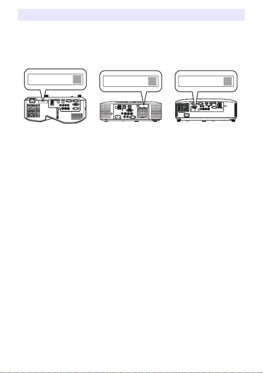
Checking the Serial Number and Board Number
XJ-OOO XXXXXXXXXX-XXXXXX
Production Date: YYYY/MM
XJ-OOO XXXXXXXXXX-XXXXXX
Production Date: YYYY/MM
XJ-OOO XXXXXXXXXX-XXXXXX
Production Date: YYYY/MM
Each projector is assigned a unique serial number and board (circuit board) number to identify it. You
can find these numbers at the locations shown below.
Serial Number
The serial number is shown on label affixed to the projector.
XJ-UT Series XJ-F Series XJ-S Series
Board Number
You can use the procedure below to display the Setup Menu “Operational Info”, which shows the
board number.
1.
Press the [MENU] key to display the setup menu.
2.
Use the [] and [] keys to select “Operational Info”.
Check the “Board Number” line.
3.
Press the [MENU] key to close the setup menu.
75
Page 76

Appendix
Note
Supplying USB Power to Another Device
The terminals in the table below can be used to supply USB power to another device.
Model Name Terminal Name Power/Current
XJ-UT312WN, XJ-UT352WN,
XJ-S400UN, XJ-S400WN
XJ-F21XN, XJ-F211WN USB-A/DC 5V port DC 5V/2A
XJ-UT352W, XJ-F11X, XJ-F101W,
XJ-S400U, XJ-S400W
Important!
Turning off projector power also cuts power being supplied to external equipment. Note that
power being supplied is also cut when the projector is turned off due to restarting by its selfcheck function or Auto Power Off, due to some error, or for any other reason. Depending on
the external equipment being used, cut off of the power supply may cause data that is being
edited to be lost or corrupted. Make it a habit to frequently save data on external equipment
being powered by the projector.
Projector power being turned off by Auto Power Off (page 64) also causes power to external
equipment to be cut off. Before starting power supply to external equipment, be sure to select
“Off” for the setting “Option Settings 1 3 Auto Power Off” to disable Auto Power Off.
For a list of external equipment whose operation has been confirmed while being powered by
the projector, visit the CASIO projector website (https://world.casio.com/faq/projector/).
Proper operation is not guaranteed for any external device that is not included in the list at the
CASIO projector website.
Though voltage and current power may be able to be supplied to devices other than those
listed on the CASIO website, note that doing so may result in some functions becoming
unavailable on some devices. Before using output from this port to power another device, be
sure to check the user documentation of the device and make sure you connect it correctly.
Particular care is required when connecting a chargeable battery to this projector’s USB port
power supply. Incorrect connection creates the risk of explosion, fire, and smoke.
Note that CASIO COMPUTER CO., LTD. shall be held in no way liable for any loss or
corruption of data stored on an external device connected to this projector’s USB port power
supply, or for any damage, smoke generation, or fire occurring on the connected device.
USB-A/DC 5V port
USB-A port
DC 5V port DC 5V/2A
DC 5V/1.5A
DC 5V/0.5A
To temporarily blank projection while maintaining power supply from the projector to external
equipment, press the [BLANK] key. For more information, see “Momentarily blank the image
and mute the audio (BLANK)” (page 49).
Even if the projection light has been turn off by Auto Projection Off (page 47), USB power will
continue to be supplied as long as the projector is turned on.
76
Page 77

Mounting the Projector on a Wall (XJ-UT Series)
You can use special wall mounting hardware to mount the projector on a wall. In this configuration, the
projector should be mounted with the top of the projector downwards.
For full details, contact the retailer where you purchased the projector.
Important!
When mounting the projector on a wall, make sure that it is at least one meter away from fire
detectors, fire alarms, and other fire protection devices. Locating the projector too close to a
fire protection device creates the risk of mis-operation of the device due to warm air
exhausted from the projector. Also, avoid locating the projector close to fluorescent lights or
other strong light sources. Bright light can shorten the operating range of the remote controller
or even make remote control impossible. When selecting a location for the projector, be sure
to test for proper operation of the remote controller.
The vertical and horizontal orientation of the projected image is reversed from normal when
the projector is positioned upside down for mounting on a wall. You need to change the setup
of the projector in order to correct for this. For details, see “Screen Settings 3 Ceiling Mount”
(page 62) under “Setup Menu Settings”.
Hanging the Projector from a Ceiling (XJ-F Series, XJ-S Series)
The projector can be hung from a ceiling. When hanging a projector from the ceiling, you can orient it
upside down or with the projection lens facing straight downwards.
For full details, contact the retailer where you purchased the projector.
Important!
When hanging the projector from a ceiling, make sure that it is at least one meter away from
fire detectors, fire alarms, and other fire protection devices. Locating the projector too close to
a fire protection device creates the risk of mis-operation of the device due to warm air
exhausted from the projector. Also, avoid locating the projector close to fluorescent lights or
other strong light sources. Bright light can shorten the operating range of the remote controller
or even make remote control impossible. When selecting a location for the projector, be sure
to test for proper operation of the remote controller.
The vertical and horizontal orientation of the projected image is reversed from normal when
the projector is positioned upside down for hanging from a ceiling. You need to change the
setup of the projector in order to correct for this. For details, see “Screen Settings 3 Ceiling
Mount” (page 62) under “Setup Menu Settings”.
77
Page 78
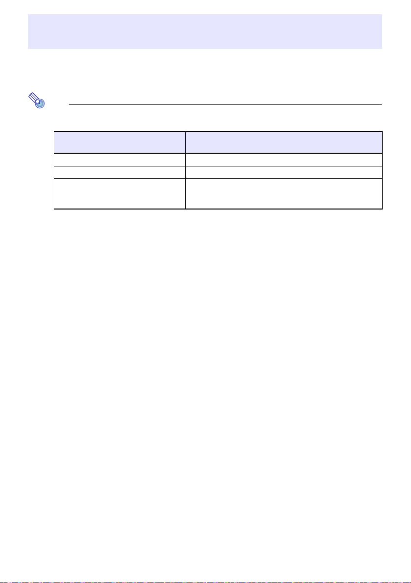
Note
Using the MONITOR OUT Terminal (XJ-UT Series, XJ-S400UN, XJ-S400WN)
The MONITOR OUT terminal of the projector outputs the video signal being input via the COMPUTER
IN 1 terminal or COMPUTER IN 2 terminal as-is. This makes it possible to simultaneously output the
projection image to another display.
The signals output from the MONITOR OUT terminal when the projector is turned on depends
on the selected input source as shown in the table below.
When this input source is selected:
Computer1 COMPUTER IN 1
Computer2 COMPUTER IN 2
Video, HDMI1, HDMI2, CASIO USB Tool,
Network
*1 For example, even if the input source is switched from Computer1 to Video, the MONITOR
OUT terminal continues output the video input signal from COMPUTER IN 1.
The projector can be configured to output, from the MONITOR OUT terminal, the video signal
input from the COMPUTER IN 1 terminal while the projector is in the standby state. For details,
see “Option Settings 2 3 Standby RGB/Audio” (page 65).
The video input signal from this terminal is output to the
MONITOR OUT terminal:
The video input signal is output from either Computer1 or
Computer2, in accordance with the last selected input source
(COMPUTER IN 1 terminal or COMPUTER IN 2 terminal).*
1
78
Page 79
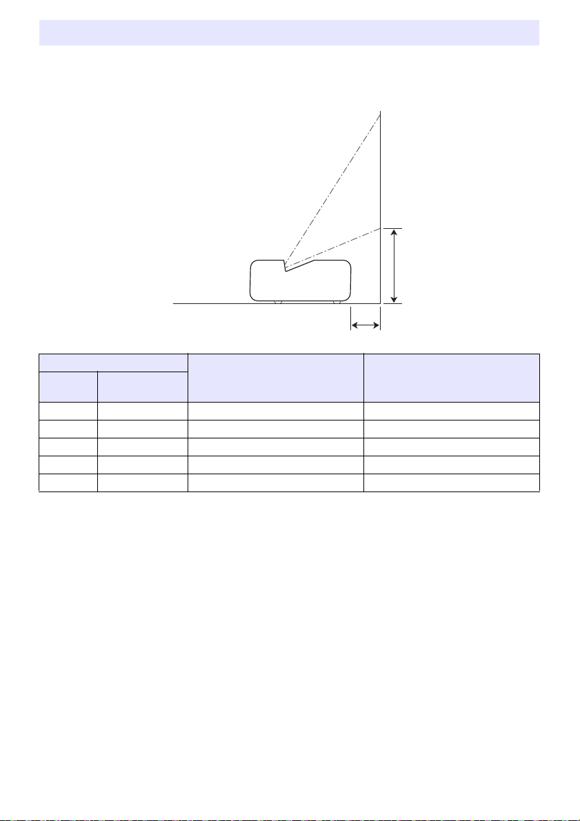
Projection Distance and Screen Size
The projection distance values below are for reference when setting up the projector.
XJ-UT Series
h
L
Projection Size
Screen
Size
50 127 6 / 2.4 24 / 9.4
60 152 13 / 5.1 27 / 10.6
80 203 27 / 10.6 32 / 12.6
100 254 40 / 15.7 38 / 15
110 279 47 / 18.5 40 / 15.7
Diagonal
(cm)
Projection Distance
(Distance to projector front):
L (cm / inch)
Height from Projector Bottom to
Screen Bottom:
h (cm / inch)
79
Page 80

XJ-F Series
h
Projection Size
Screen
Size
30 76 0.93 / 3.05 1.38 / 4.53 0 – – –
35 89 – – – 0.92 / 3.02 1.37 / 4.49 8 / 3.15
40 102 1.27 / 4.17 1.88 / 6.17 0 1.06 / 3.48 1.58 / 5.18 9 / 3.54
60 152 1.95 / 6.4 2.87 / 9.42 0 1.64 / 5.38 2.42 / 7.94 13 / 5.12
77 196 2.54 / 8.33 3.72 / 12.2 0 2.14 / 7.02 3.14 / 10.3 17 / 6.69
80 203 2.64 / 8.66 3.86 / 12.66 0 2.22 / 7.28 3.26 / 10.7 18 / 7.09
100 254 3.33 / 10.93 4.85 / 15.91 0 2.81 / 9.22 4.11 / 13.48 22 / 8.66
150 381 5.04 / 16.54 7.33 / 24.05 0 4.26 / 13.98 6.22 / 20.41 34 / 13.39
200 508 6.76 / 22.18 9.82 / 32.22 0 5.72 / 18.77 8.32 / 27.3 45 / 17.72
300 762 10.18 / 33.4 14.78 / 48.49 0 8.63 / 28.31 12.54 / 41.14 67 / 26.38
Diagonal
(cm)
XJ-F11X/XJ-F21XN XJ-F101W/XJ-F211WN
Minimum
Distance
(m / feet)
Approximate Projection Distance
Maximum
Distance
(m / feet)
h
Minimum
Distance
(m / feet)
Maximum
Distance
(m / feet)
(cm / inch)
h
80
Page 81

XJ-S Series
h
Projection Size
Screen
Size
100 254 2.80 / 9.19 4.70 / 15.42 23 / 9.06 2.94 / 9.65 4.94 / 16.21 20 / 7.87
150 381 4.25 / 13.94 7.10 / 23.29 34 / 13.39 4.47 / 14.67 7.46 / 24.48 31 / 12.20
200 508 5.70 / 18.70 9.50 / 31.17 45 / 17.72 5.99 / 19.65 9.99 / 32.78 41 / 16.14
300 762 8.60 / 28.22 14.30 / 46.92 68 / 26.77 9.04 / 29.66 15.03 / 49.31 61 / 24.02
Diagonal
(cm)
30 76 0.77 / 2.53 1.34 / 4.40 7 / 2.76 0.81 / 2.66 1.41 / 4.63 6 / 2.36
40 102 1.06 / 3.48 1.82 / 5.97 9 / 3.54 1.11 / 3.64 1.91 / 6.27 8 / 3.15
60 152 1.64 / 5.38 2.78 / 9.12 14 / 5.51 1.72 / 5.64 2.92 / 9.58 12 / 4.72
77 196 2.13 / 6.99 3.59 / 11.78 17 / 6.69 2.24 / 7.35 3.78 / 12.40 16 / 6.30
80 203 2.22 / 7.28 3.74 / 12.27 18 / 7.09 2.33 / 7.64 3.93 / 12.89 16 / 6.30
XJ-S400U/XJ-S400UN XJ-S400W/XJ-S400WN
Minimum
Distance
(m / feet)
Approximate Projection Distance
Maximum
Distance
(m / feet)
h
(cm / inch)
Minimum
Distance
(m / feet)
Maximum
Distance
(m / feet)
(cm / inch)
h
81
Page 82

Aspect Ratio Setting and Projection Image
The following shows how images are projected in accordance with the type of the input signal and the
aspect ratio setting of the projector.
WXGA models (1280 × 800), WUXGA models (1920 × 1200)
Input source: RGB, HDMI(PC), CASIO USB Tool, Network or Templates
Input Signal Normal Full 16:9 4:3 True
SVGA (800 × 600)
XGA (1024 × 768)
WXGA (1280 × 800)
SXGA (1280 × 1024)
Input source: Video, Component or HDMI(DTV)
Input Signal Normal 16:9 16:10 4:3 Letter Box
4:3 Aspect Image
Squeezed Image
Letter Box Image
16:9 Aspect Image
82
Page 83

XGA models (1024 × 768)
Input source: RGB, HDMI(PC), CASIO USB Tool, Network or Templates
Input Signal Normal Full 16:9 16:10
SVGA (800 × 600)
XGA (1024 × 768)
WXGA (1280 × 800)
SXGA (1280 × 1024)
Input source: Video, Component or HDMI(DTV)
Input Signal Normal 16:9 16:10 4:3
4:3 Aspect Image
Squeezed Image
Letter Box Image
16:9 Aspect Image
83
Page 84

Supported Signals
RGB (VESA) 640 × 480/60
640 × 480/72
640 × 480/75
640 × 480/85
800 × 600/56
800 × 600/60
800 × 600/72
800 × 600/75
800 × 600/85
1024 × 768/60
1024 × 768/70
1024 × 768/75
1024 × 768/85
1152 × 864/75
1280 × 720/60
1280 × 768/60
1280 × 800/60
1280 × 960/60
1280 × 1024/60
1280 × 1024/75
1280 × 1024/85
1366 × 768/60
1400 × 1050/60
1440 × 900/60
1600 × 1200/60
1680 × 1050/60
1920 × 1080/60
1920 × 1200RB/60
Video NTSC, NTSC4.43, PAL, PAL-M,
PAL-N, PAL60, SECAM
Component
(HDTV)
1080p/50
1080p/60
720p/50
720p/60
1080i/50
1080i/60
Component
(SDTV)
576p/50
576i/50
480p/60
480i/60
HDMI 640 × 480/60
800 × 600/60
1024 × 768/60
1280 × 720/60
1280 × 768/60
1280 × 800/60
1280 × 960/60
1280 × 1024/60
1400 × 1050/60
1920 × 1080/60
1920 × 1200RB/60
SDTV (480p)
SDTV (576p)
HDTV (720p) (50)
HDTV (720p) (60)
HDTV (1080i) (50)
HDTV (1080i) (60)
HDTV (1080p) (50)
HDTV (1080p) (60)
84
Page 85

Projector RS-232C Control
(
VOL ?
)
(
0-30,15
)
(
VOL 0
)
To control the projector using RS-232C commands from a computer, you need to connect the
projector and computer using a commercially available serial cable (cross).
Command Send Format
Communication
Protocol
Read Command Send Format (<command name>?)
Write Command Send Format (<command name><setting value>)
All commands use ASCII characters and decimal format integers.
The projector will return a question mark (?) when it is sent a command it cannot recognize. Any
setting value that cannot be recognized by the projector will be ignored.
If the projector is performing a process initiated by a previously sent command, a projector key
operation, or a remote controller key operation, send of the next command must wait until the
projector completes the previous process.
Data Rate: 19200 bps, Data Bit: 8 bit, Parity: None, Stop Bit: 1 bit, Flow Control: None
Receive Format (<applicable command setting range>,<current setting>)
Command Send Example sent from the computer to the projector.
4
returned from the projector to the computer.
Command Send Example sent from the computer to the projector.
4
Projector volume setting becomes 0.
85
Page 86

Command List
R
W
R
W
W
W
While the projector is turned off, it can receive only following commands: check power on/off state
(PWR?), read light time (LMP?), and write power on (PWR1). Do not try to send any other
commands to the projector while it is turned off.
Input of a valid signal must be in progress in order to use a command to turn on blank screen or
change the aspect ratio.
You can use only the commands and settings that are equipped on your projector model.
Entries in the “Function” column of the table below indicate that a command is read-only ( ) or
write only ( ).
Command
Name
HKS*
HKP*
HKM*
W
Function Settings
PWR Power On/Off 0: Off, 1: On
SRC Selecting the Input
Source:
0: RGB1, 1: Component 1, 2: Video, 3: RGB2, 4: Component 2
6: Auto1 (RGB/Component), 7: HDMI1, 8: Network
10: Auto2 (RGB/Component), 13: CASIO USB Tool, 14: HDMI2
15: Templates
AIS Selecting the Audio Input 0: AUDIO IN, 1: AUDIO IN 1, 2: AUDIO IN 2, 3: AUDIO IN R L
4: HDMI AUDIO IN, 5: HDMI1 AUDIO IN, 6: HDMI2 AUDIO IN
8: Network AUDIO
BLK Blank Screen 0: Off, 1: On
VOL Volume*
1
0 (mute) to 30 (maximum volume)
VLP VLP specifies, as a numeric value, how much volume should be increased. VLM specifies
VLM
how much it should be decreased. For example, to change volume by a factor of 5, send “VLP5”
to increase it or “VLM5” to decrease it.
MUT Mute 0: Off, 1: On
PST Color Mode 1: Graphics, 2: Theater, 3: Standard, 4: Blackboard, 5: Natural
6: Vivid (XJ-S Series only), 7: DICOM Simulation (XJ-S Series only)
2
ARZ Aspect Ratio 0: Normal*
, 1: 16:9, 2: Normal*2, 3: Letter Box, 4: Full, 5: True
6: 4:3, 7: 16:10
LMP Reads the cumulative light time (Returns the number of hours as an integer value.)
3
PMD Light Control 0: Bright*
, 1: Normal*3, 2: Light Sensor On, 3: Light Output 7
4: Light Output 6, 5: Light Output 5, 6: Light Output 4
7: Light Output 3, 8: Light Output 2, 9: Light Output 1
FRZ Freeze 0: Off, 1: On
KST Vertical Keystone
0 to 120*
4
Correction
KSP KSP specifies, as a numeric value, how much vertical keystone correction should be
KSM
increased. KSM specifies how much it should be decreased. For example, to change vertical
keystone correction by a factor of 5, send “KSP5” to increase it or “KSM5” to decrease it.
5
Horizontal Keystone
0 to 120*
4
Correction
5
5
KEY Executes key press
HKP specifies, as a numeric value, how much horizontal keystone correction should be
increased. HKM specifies how much it should be decreased. For example, to change horizontal
keystone correction by a factor of 5, send “HKP5” to increase it or “HKM5” to decrease it.
operation.*
6
1: , 2: , 3: , 4: , 5: ENTER, 6: ESC, 10: FUNC, 11: MENU
12: POWER, 13: AUTO, 14: INPUT, 15: TIMER, 16: ASPECT
17: BLANK, 18: FREEZE, 19: , 20: KEYSTONE +
21: KEYSTONE –, 22: D-ZOOM +, 23: D-ZOOM –, 24: VOLUME +
25: VOLUME –, 31: ID2, 32: ID1, 33: ID4, 34: ID3
86
Page 87

Command
R
Name
POS Setup Type*
APO Auto Power Off 0: Off, 1: 5 minutes, 2: 10 minutes, 3: 15 minutes, 4: 20 minutes
STS Reads the projector
MIC Microphone Input Level 0 to 3
IDS Projector ID 0: All, 1: ID1, 2: ID2, 3: ID3, 4: ID4
ALC RGB1 Level Adjust 0: Off, 1: On
AL2 RGB2 Level Adjust 0: Off, 1: On
ASO Auto Projection Off 0: Disable, 1: Enable
ASS Auto Input Search 0: Off, 1: On
TIM Timer Type 0: Presentation, 1: Countdown
TIT Countdown Timer Time 0 (0H00M00S) - 35999 (9H59M59S)
8
TMP*
MIR Mirror Mode 0: Off, 1: On
BSN Board Number Shows the board number (page 75).
Function Settings
7
error status.
Template Type 0: Lines (Large), 1: Lines (Medium), 2: Lines (Small), 3: Grid (Large),
R
0: Projection with top of projector upwards, screen in front
1: Projection with top of projector downwards, screen in back
2: Projection with top of projector upwards, screen in back
3: Projection with top of projector downwards, screen in front
5: 30 minutes
0: Normal, 1: Fan error, 2: Temperature error, 7: Light error
16: Other error
4: Grid (Medium), 5: Grid (Small), 6: Dot Grid (Large),
7: Dot Grid (Small), 8: 2 x 2 Area
*1 This setting is applied to the input source signal that is currently being projected by the projector.
*2 Setting 0 is the “Normal” setting when the input source is RGB or HDMI(PC), while setting 2 is the
“Normal” setting when the input source is component, HDMI(DTV), or Video.
*3 Light Control Off Mode settings.
*4 The setting range on the projector setup menu is –60 to 60.
*5 XJ-UT Series only
*6 Each KEY command setting corresponds to a remote controller key. The projector operation that is
performed in response to a KEY command is identical to the corresponding remote controller key
operation. When sending KEY commands to the projector from an external device, make sure they
are sent in the same sequence that the corresponding key operations are performed on the remote
controller.
*7 Specifies how the projector is set up relative to screen for projection. Corresponds to the projector
setup menu “Projection Mode” and “Ceiling Mount” commands.
*8 XJ-UT352W, XJ-F11X, XJ-F101W, XJ-S400U, XJ-S400W models only
87
Page 88

Specifications
All Series
Display system DLP® chip × 1, DLP® system
Light Source Laser and LED
Gamut Full color (up to 1.07 billion colors)
Contrast Ratio (Full White / Black) *
Scanning
Frequencies
Display
Resolution
Terminals Digital Video Input HDMI terminal: HDCP support, audio signal support
Wireless Support IEEE 802.11b/g/n compatible (YW-41 wireless adapter connection is
Speaker 16W × 1, Monaural
Operating Temperature 5 to 35°C (41 to 95°F)
Operating Humidity 20 to 80% (non-condensation)
Operating Altitude 0 to 3,000 meters (0 to 10,000 feet) above sea level
Power Requirements 100 to 240VN(AC), 50/60Hz
Horizontal 15 to 91 kHz
Vertical 50 to 85 Hz
Component Signal Maximum: 1920 × 1080 (HDTV 1080P)
HDMI Signal Maximum: 1920 × 1200 resizing
Video Signal NTSC, PAL, PAL-N, PAL-M, PAL60, SECAM
Analog Video Input Composite (RCA) terminal × 1
Audio Input RCA R/L terminals
Audio Output 3.5 mm stereo mini jack × 1
USB Host USB type A×2 (XJ-UT312WN, XJ-UT352WN, XJ-S400UN,
USB Device Micro-USB type B × 1: For firmware update and logo data registration
Control Terminal RS-232C (D-sub 9 pin) × 1
LAN Terminal RJ-45 × 1 (Network models only)
1 *2
HDMI type A×1 (XJ-UT312WN)
HDMI type A×2 (XJ-UT352W, XJ-UT352WN, XJ-F Series and
3.5 mm stereo mini jack × 2 (XJ-UT Series models, XJ-S400UN,
3.5 mm stereo mini jack × 1 (XJ-F Series models, XJ-S400U,
USB type A×1 (XJ-F21XN, XJ-F211WN)
supported by network models only.)
20000:1
XJ-S Series models)
XJ-S400WN)
XJ-S400W)
XJ-S400WN)
88
Page 89

XJ-UT Series
Model Name XJ-UT312WN XJ-UT352W XJ-UT352WN
Display Chip Chip Size WXGA 0.65 inches (Aspect ratio: 16:10)
Number of Pixels 1,024,000 (1280 × 800)
Projection Lens Fixed zoom, manual focus
F 2.3 / f 4.2
Projected Image Size 50 to 110 inches
Projection
Distance
Brightness *
RGB Signal Display Resolution Native: 1280 × 800
Terminals
Power Consumption (100 to 240V)
Light Output 7 when “Light Control” is
“On”
Light Output 1 when “Light Control” is
“On”
When “Bright” is selected for “Light
Control Off Mode”
When “Normal” is selected for “Light
Control Off Mode”
Standby Power Consumption (100 to 120V)
When “Disable” is specified for
“Remote On” *
When “Enable” is specified for
“Remote On” *
Standby Power Consumption (220 to 240V)
When “Disable” is specified for
“Remote On” *
When “Enable” is specified for
“Remote On” *
Approximate Dimensions *
Approximate Weight *
60 inches 0.13 meters (0.4 feet)
100 inches 0.40 meters (1.3 feet)
Minimum Projection
Distance
1 *2
3100 lumens 3500 lumens
0.06 meters (0.2 feet)
Maximum: 1920 × 1200 resizing
RGB Input
Component Input
COMPUTER terminal: RGB 15-pin mini D-Sub × 2
Used for both RGB input and component (YCbCr/YPbPr) input.
RGB Output MONITOR OUT terminal: RGB 15-pin mini D-Sub × 1
Mic Input *
3
USB-A
Power Supply Port *
DC 5V × 1 DC 5V × 1 DC 5V × 1
4
3.5 mm monaural mini jack × 1
USB-A Port 1 – 1
160W 185W
90W 105W
195W 225W
170W 200W
5
5
5
5
6
338 (W) × 333 (D) × 153 (H) mm (13.3" × 13.1" × 6")
0.6W (Network models only)
0.8W (Network models only)
0.12W
0.23W
(Including projections)
6
5.8kg (12.8lbs)
89
Page 90
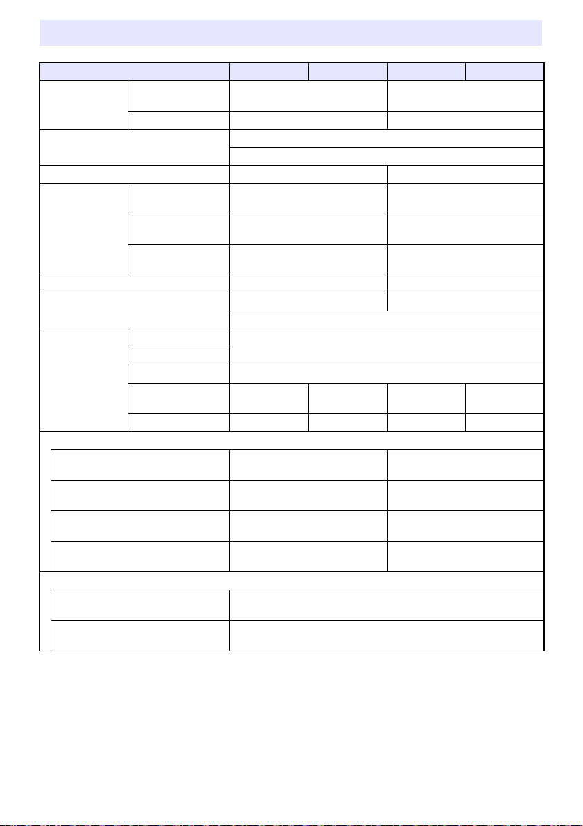
XJ-F Series
Model Name XJ-F11X XJ-F21XN XJ-F101W XJ-F211WN
Display Chip Chip Size XGA 0.55 inches
(Aspect ratio: 4:3)
Number of Pixels 786,432 (1024 × 768) 1,024,000 (1280 × 800)
Projection Lens 1.5X manual zoom, manual focus
F 2.31 to 2.73 / f 18.9 to 27.2
Projected Image Size 30 to 300 inches 35 to 300 inches
Projection
Distance
60 inches 1.95 to 2.87 meters
(6.4 to 9.4 feet)
100 inches 3.33 to 4.85 meters
(10.9 to 15.9 feet)
Brightness *
Minimum Projection
Distance
1 *2
0.93 meters (3.1 feet) 0.92 meters (3.0 feet)
3300 lumens 3500 lumens
RGB Signal Display Resolution Native: 1024 × 768 Native: 1280 × 800
Maximum: 1920 × 1200 resizing
Terminals RGB Input
Component Input
Mic Input *
USB-A
Power Supply Port *
3
4
COMPUTER terminal: RGB 15-pin mini D-Sub × 1
Used for both RGB input and component (YCbCr/YPbPr) input.
3.5 mm monaural mini jack × 1 (Network models only)
DC 5V × 1 DC 5V × 1 DC 5V × 1 DC 5V × 1
USB-A Port – 1 – 1
Power Consumption (100 to 240V)
Light Output 7 when “Light Control” is
“On”
Light Output 1 when “Light Control” is
“On”
When “Bright” is selected for “Light
Control Off Mode”
When “Normal” is selected for “Light
Control Off Mode”
160W 165W
80W 85W
195W 205W
170W 175W
Standby Power Consumption (100 to 120V)
When “Disable” is specified for
“Remote On” *
When “Enable” is specified for
“Remote On” *
5
5
0.6W (Network models only)
0.12W
WXGA 0.65 inches
(Aspect ratio: 16:10)
1.64 to 2.42 meters
(5.4 to 7.9 feet)
2.81 to 4.11 meters
(9.2 to 13.5 feet)
90
Page 91

Model Name XJ-F11X XJ-F21XN XJ-F101W XJ-F211WN
Standby Power Consumption (220 to 240V)
When “Disable” is specified for
“Remote On” *
When “Enable” is specified for
“Remote On” *
5
5
0.8W (Network models only)
0.23W
Approximate Dimensions 299 (W) × 299 (D) × 97 (H) mm (11.8" × 11.8" × 3.8")
(Including projections)
Approximate Weight 3.8kg (8.4lbs)
XJ-S Series
Model Name XJ-S400U XJ-S400UN XJ-S400W XJ-S400WN
Display Chip Chip Size WUXGA 0.67 inches
(Aspect ratio: 16:10)
Number of Pixels 2,304,000 (1920 × 1200) 1,024,000 (1280 × 800)
Projection Lens 1.7X manual zoom, manual focus
F 2.33 to 3.03 / f 19.5 to 32.3
Projected Image Size 30 to 300 inches 30 to 300 inches
Projection
Distance
60 inches 1.64 to 2.78 meters
(5.4 to 9.1 feet)
100 inches 2.80 to 4.70 meters
(9.2 to 15.4 feet)
Minimum Projection
Distance
Brightness *
1 *2
RGB Signal Display Resolution
Terminals RGB Input,
Component Input
(COMPUTER
terminal)
0.77 meters (2.5 feet) 0.81 meters (2.7 feet)
4000lm
Native: 1920 × 1200
RGB 15-pin mini D-Sub × 2 (XJ-S400UN, XJ-S400WN)
RGB 15-pin mini D-Sub × 1 (XJ-S400U, XJ-S400W)
Used for both RGB input and component (YCbCr/YPbPr) input.
RGB Output MONITOR OUT terminal: RGB 15-pin mini D-Sub × 1
(Network models only)
Mic Input *
USB-A Power Supply
Port *
3
4
3.5 mm monaural mini jack × 1 (Network models only)
DC 5V×1 DC 5V×1 DC 5V×1 DC 5V×1
USB-A Port – 1 – 1
WXGA 0.65 inches
(Aspect ratio: 16:10)
1.72 to 2.92 meters
(5.7 to 9.6 feet)
2.94 to 4.94 meters
(9.7 to 16.2 feet)
Native: 1280 × 800
Maximum: 1920 × 1200 resizing
91
Page 92

Model Name XJ-S400U XJ-S400UN XJ-S400W XJ-S400WN
Power Consumption (100 to 240V)
Light Output 7 when “Light Control” is
“On”
Light Output 1 when “Light Control” is
“On”
When “Bright” is selected for “Light
Control Off Mode”
When “Normal” is selected for “Light
Control Off Mode”
Standby Power Consumption (100 to 120V)
When “Disable” is specified for
“Remote On” *
When “Enable” is specified for
“Remote On” *
Standby Power Consumption (220 to 240V)
When “Disable” is specified for
“Remote On” *
When “Enable” is specified for
“Remote On” *
Approximate Dimensions 357 (W) × 337 (D) × 124 (H) mm (14.1" × 13.3" × 4.9")
Approximate Weight 5.9kg (13.0lbs)
5
5
5
5
210W 215W 210W 215W
120W 125W 120W 125W
250W 255W 250W 255W
215W 220W 215W 220W
0.09W
0.6W (Network models only)
0.17W
0.8W (Network models only)
(not including projections)
*1 When the “Light Control Off Mode” setting is “Bright”. ISO 21118:2012 standard.
*2 Shows overall average value when the projector is shipped from the factory. This type of entry is
governed by ISO 21118:2012 data projector specifications. Measurement methods and conditions
are based on Appendix B.
*3 Plug-in power type microphones are not supported.
*4 With a network model, the USB Host port also serves as a USB power supply port.
*5 For information about configuring the Remote On setting, see “Network Settings 3 Network
Settings 3 Remote On” (page 66).
*6 Excluding cable cover.
Specifications are subject to change without notice.
92
Page 93

TCO Certified Document URL
https://world.casio.com/projector/tco/
93
Page 94
GUIDELINES LAID DOWN BY FCC RULES FOR USE OF THIS UNIT IN THE U.S.A. (not
XJ-UT312WN/XJ-UT352W/
XJ-UT352WN/XJ-F11X/XJ-F21XN/
XJ-F101W/XJ-F211WN/XJ-S400U/
XJ-S400UN/XJ-S400W/XJ-S400WN
FOR CALIFORNIA USA ONLY
Perchlorate Material – special handling may apply.
See www.dtsc.ca.gov/hazardouswaste/perchlorate.
applicable to other areas).
NOTICE
This equipment has been tested and found to comply with the limits for a Class B digital device,
pursuant to Part 15 of the FCC Rules. These limits are designed to provide reasonable protection
against harmful interference in a residential installation. This equipment generates uses and can
radiate radio frequency energy and, if not installed and used in accordance with the instructions, may
cause harmful interference to radio communication. However, there is no guarantee that interference
will not occur in a particular installation. If this equipment does cause harmful interference to radio
or television reception, which can be determined by turning the equipment off and on, the user is
encouraged to try to correct the interference by one or more of the following measures:
Reorient or relocate the receiving antenna.
Increase the separation between the equipment and receiver.
Connect the equipment into an outlet on a circuit different from that to which the receiver is connected.
Consult the dealer or an experienced radio/TV technician for help.
FCC CAUTION
Changes or modifications not expressly approved by the party responsible for compliance could void
the user’s authority to operate the equipment.
Proper connectors must be used for connection to host computer and/or peripherals in order to meet
FCC emission limits.
Connector cable.... XJ-UT312WN/XJ-UT352W/XJ-UT352WN/XJ-F11X/XJ-F21XN/XJ-F101W/
Model Number: XJ-UT312WN/XJ-UT352W/XJ-UT352WN/XJ-F11X/XJ-F21XN/XJ-F101W/XJ-F211WN/
Trade Name: CASIO COMPUTER CO., LTD.
Responsible party: CASIO AMERICA, INC.
Address: 570 MT. PLEASANT AVENUE, DOVER, NEW JERSEY 07801
Telephone number: 973-361-5400
This device complies with Part 15 of the FCC Rules, Operation is subject to the following two conditions:
(1) This device may not cause harmful interference, and (2) this device must accept any interference
received, including interference that may cause undesired operation.
This Class B digital apparatus complies with Canadian ICES-003.
Cet appareil numérique de la classe B est conforme à la norme NMB-003 du Canada.
XJ-F211WN/XJ-S400U/XJ-S400UN/XJ-S400W/XJ-S400WN unit to PC
Declaration of Conformity
XJ-S400U/XJ-S400UN/XJ-S400W/XJ-S400WN
94
Page 95

GPL and LGPL
(1) This product uses software (This Software) that comes under the GNU General Public License
(GPL) and GNU Lesser General Public License (LGPL). In accordance with the GPL and LGPL, the
source code of This Software is open source code. Anyone who wishes to view the open source
code can do so by downloading it from the CASIO Projector download site. Whenever copying,
modifying, or distributing This Software, be sure to do so in accordance with the terms and
conditions of the GPL and LGPL.
(2) This Software is provided “as is” without expressed or implied warranty of any kind. However, this
disclaimer does not affect the terms and conditions of the warranty of the product itself (including
malfunctions due to This Software).
(3) For details about the GPL and LGPL that This Software comes under, visit the CASIO website.
Manufacturer:
CASIO COMPUTER CO., LTD.
6-2, Hon-machi 1-chome, Shibuya-ku, Tokyo 151-8543, Japan
Responsible within the European Union:
Casio Europe GmbH
Casio-Platz 1, 22848 Norderstedt, Germany
www.casio-europe.com
95
Page 96

MA1904-A
 Loading...