

Page 1

Basic Information for
INDEX
Casio Pocket Television
Vol.3 CIRCUIT OPERATION
Contents
PAGE
TELEVISION TRANSMISSION SYSTEM ...........................................................
Color System ....................................................................................................
TV System ........................................................................................................
Channel System ................................................................................................
Details of Color System ....................................................................................
Details of TV System ........................................................................................
Details of TV Channel ......................................................................................
World TV Broadcast System ............................................................................
Casio TV Model ................................................................................................
BLOCK DIAGRAM ..............................................................................................
VHF, UHF .........................................................................................................
Rod Antenna ....................................................................................................
PCB Ass'y ........................................................................................................
Display Ass'y ....................................................................................................
AD PCB ............................................................................................................
Back Light ........................................................................................................
Power Supply ...................................................................................................
CIRCUIT OPERATION .......................................................................................
Tuner ................................................................................................................
IC200 ...............................................................................................................
IC300 ................................................................................................................
IC400 ................................................................................................................
IC700 ................................................................................................................
Tuning Operation ..............................................................................................
Adjustment .......................................................................................................
Troubleshooting ...............................................................................................
Trouble example ..............................................................................................
SCHEMATIC DIAGRAM & WAVEFORMS .........................................................
Waveforms ......................................................................................................
1
1
1
1
2
2
3
5
6
7
7
7
8
8
9
9
9
11
11
12
13
16
17
18
19
20
28
29
32
Page 2
TELEVISION TRANSMISSION SYSTEM
Three Systems
TV transmissionsystemsarenotthesamethroughoutth eworld:Colorsystem, TV system andChannelaredifferent.T he
countriesforwhich aparticular model issuitableareindicatedi n t he salesliteratureandinstructionbookletsupplied, andare
printedonthe box inwhicheach televisionispacked.
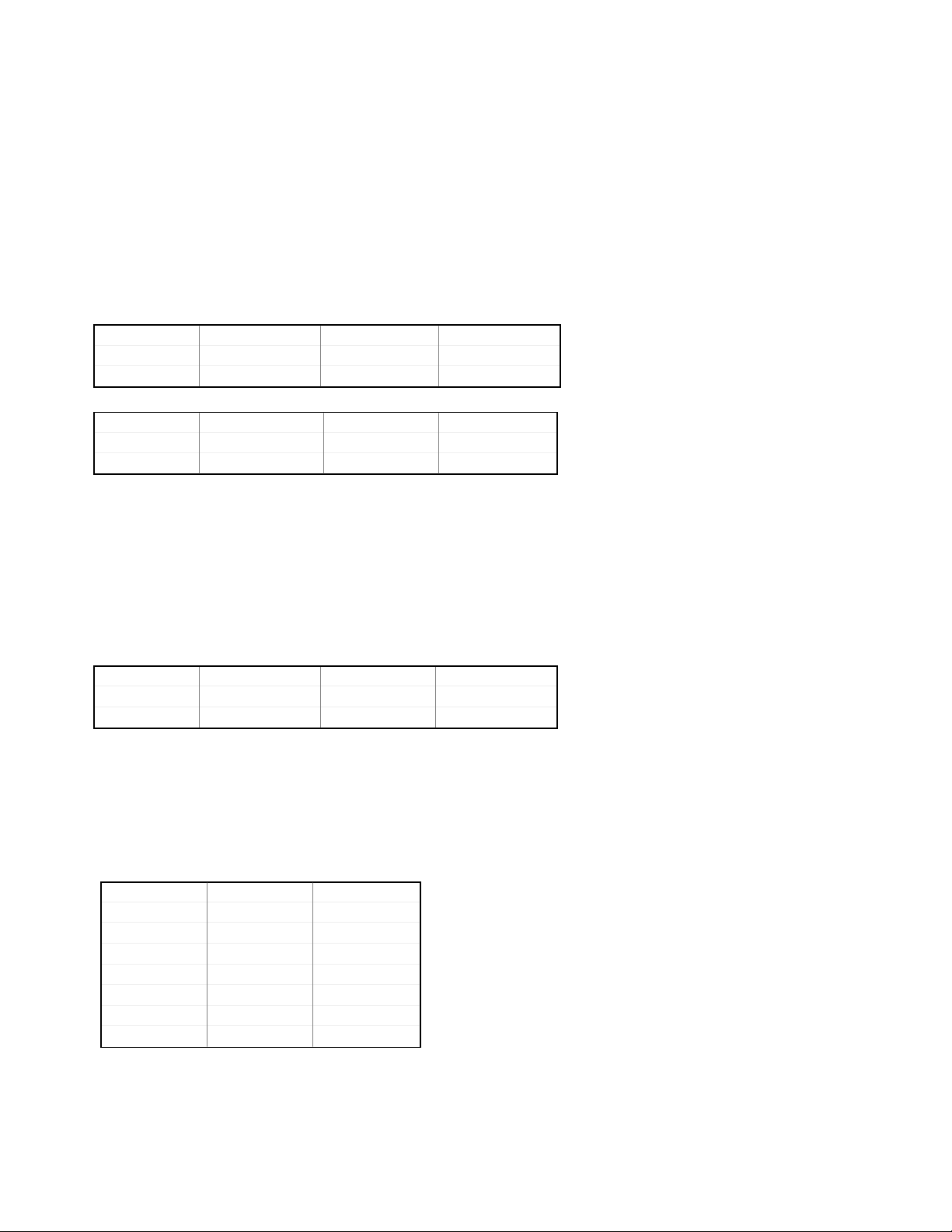
Color system
Therearethree colortransmissionsystemsintheworld:NTSC,PALandSECAM.
Ifthe color systemsaredifferent,TV doesnotg etin color.
e.g.
ColorSystem TVSystem ChannelSystem
Brazil PAL M/M US
U.S.A. NTSC M/M US
ColorSystem TVSystem ChannelSystem
SaudiArabia SECAM B/G,H CCIR
German y PAL B/G,H CCIR
T V System
Therearefourteen TVsystemsin the world: From A to N. Eachsystemisdiffer ent fromscanningline, sound
frequencyandmodulation system.
Ifthe TV systems aredifferent, TVdoesnot getapicture andasound.
TVsystemsareindicatedi n the rating plateon the lower case.
e.g.
ColorSystem TVSystem ChannelSystem
Brazil PAL M/M US
Argentina PA L N/N US
Channel System
Ifthe channel(TVfrequency)isdifferent,TVcannotget th e local channel.
e.g.
Japan U.S.A.
ColorSystem NTSC NTSC
TVSystem M/M M/M
Channel Japan US
1ch 91.25MHz 2ch 97.25MHz 55.25MHz
3ch 103.25MHz 61.25MHz
4ch 171.25MHz 67.25MHz
It is no t possible t o convert it t o work i n a ny country otherthanthe o ne for which it is designed.
-1-
Page 3
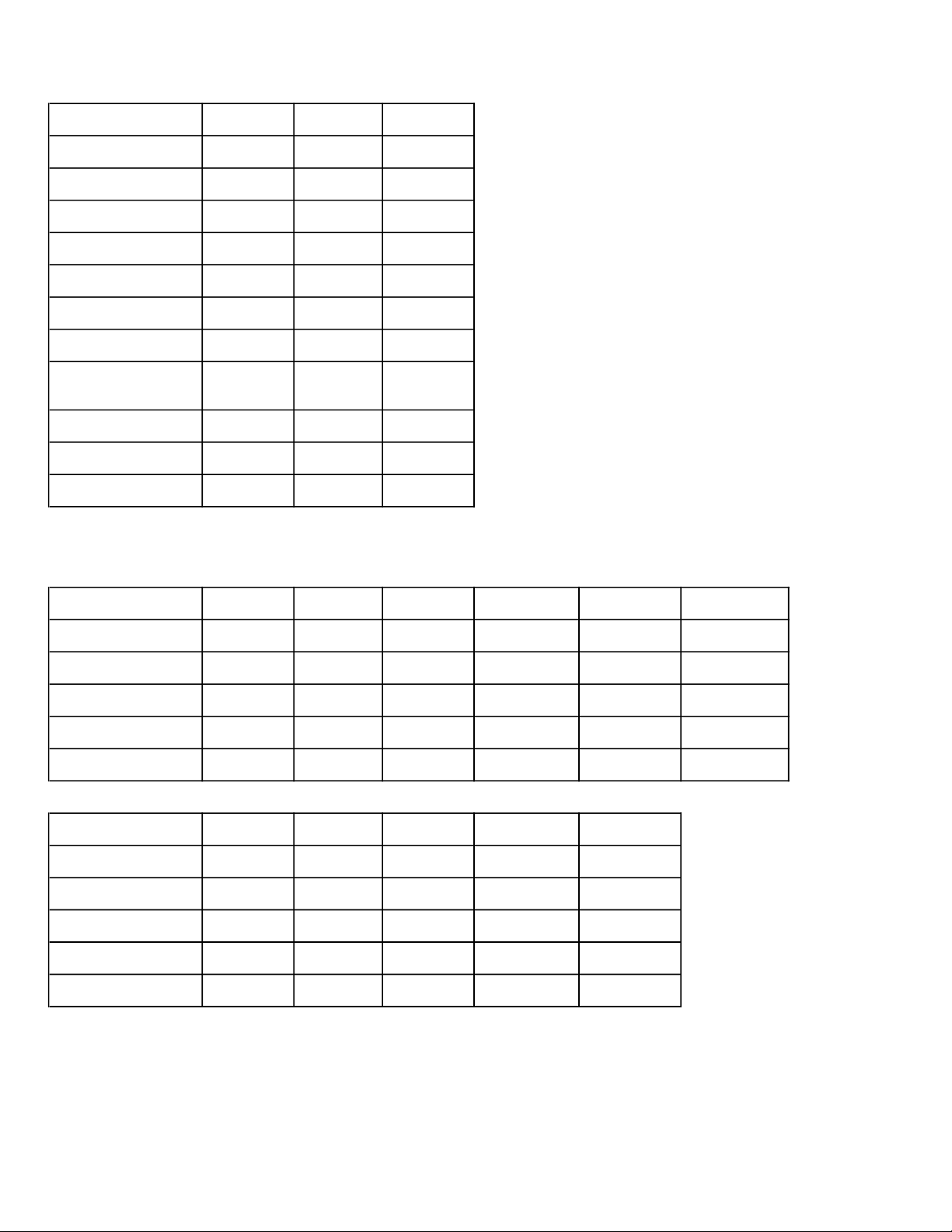
Details of Color System
System NTSC PAL SECAM NTSC: A 525-line 60-field color television system
(Germany) (France) originally developed in the USA.
Scanning lines 525 625 625 The 3.58MHz sub carrier is used to
transmit color information.
Field frequency (MHz) 59.94 50 50
PAL: A 625-line 50-field color television system
Interlacing ration 2 : 1 2 : 1 2 : 1 originally developed in West Germany.
PAL is improved about the phase distortion
Aspect ration 4 : 3 4 : 3 4 : 3 of NTSC. PAL is basically the same as
NTSC. But PAL is different from NTSC in
Line frequency (MHz) 15.734 15.625 15.625 the way of the color signal transmission.
The phase of B-Y signal is fixed 90 degree.
Channel bandwidth(MHz) 6 8 8 The phase of R-Y signal changes at 0 and
180 degree on every horizontal scanning
Luminance signal(MHz) 4.2 5 6 line. The influence of the phase distortion is
denied by this way.
Color signal (MHz) I 1.5 R-Y 1.3 R-Y 1.3 The 4.43MHz sub carrier is used to transmit
Q 0.5 B-Y 1.3 B-Y 1.3 color information.
Sound carrier-frequency +4.5 +5.5 +6.5 SECAM: A 625-line 50-field color television
(MHz) system originally developed in France.
Video Modulation AM negative AM negative AM positive Sub carrier frequency is different from
every lines, R-Y signal:4.40MHz, B-Y
Sound modulation FM FM AM signal 4.25MHz, the phase of sub
carrier changes over beginning of
scanning lines. The merit of SECAM is
strong about phase jitters, and have not
cross talk both of two color signals.
Details of TV System
System CCIR Belgium OIRT(1) France Luxembourg CCIR
(VHF) (VHF)
Broadcast System B C D E F G,H
Scanning line 625 625 625 819 819 625
Channel bandwidth 7 MHz 7 MHz 8 MHz 14 MHz 7 MHz 8 MHz
fs(audio) - fv(video) +5.5MHz +5.5MHz +6.5MHz +11.5MHz +5.5MHz +5.5MHz
Audio modulation F3(+/-50kHz) A3 F3(+/-50kHz) A3 A3 F3(+/-50kHz)
System UK(UHF), OIRT(2) France USA USA 625
Ireland (UHF) (Argentina)
Broadcast System I K,K1 L M N
Scanning line 625 625 625 525 625
Channel bandwidth 8 MHz 8 MHz 8 MHz 6 MHz 6 MHz
fs(audio) - fv(video) +6.0MHz +6.5MHz +6.5MHz +4.5MHz +4.5MHz
Audio modulation F3(+/-50kHz) F3(+/-50kHz) A3 F3(+/-25kHz) F3(+/-25kHz)
A3: AM CCIR: International OIRT Organization
F3: FM Radio International de
Consultative Radio diffusion
Committee Television
- 2 -
Page 4
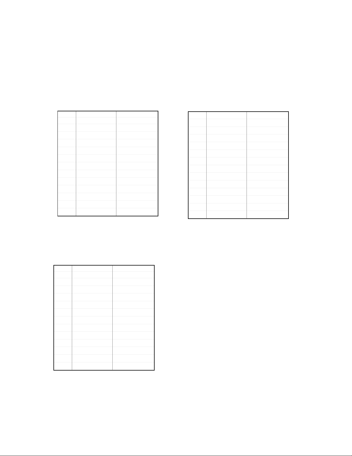
Details o f TV Channel
1) TV Channel
In the United States, the low band of television stations occupies the frequency range 54 - 88MHz, with a small gap of
4MHzbetweenchannel 4 and 5. (This band -72 to 76MHz-is usedby otherservices.)Betweenthelow-bandandthe high
band stations there isafrequencyspace (88 - 174MHz)that isoccupied by FM broadcastinga nd government and aircraft
communicationsservices.
Channel 14, thefirst of UHF channels, occupies the band 47 0 - 476MHz, channel 15, 476 - 482MHz, channel 16, 48 2 488MHz,and so on,all the wayup to890MHz.Within this band,470 - 890MHz(atotalof 420MHz),70 televisionchannels
areaccommodated. Likethe UHFallocations,eachUHFtelevision channelis6MHzwide.
JapanVHFChannel
CH.NO. VideoFrequency Sound Frequency
IF 58.75MHz 54.25MHz
1 91.25MHz 95.75MHz
2 97.25MHz 101.75MHz
3 103.25MHz 107.75MHz
4 171.25MHz 175.75MHz
5 177.25MHz 181.75MHz
6 183.25MHz 187.75MHz
7 189.25MHz 193.75MHz
8 193.25MHz 197.75MHz
9 199.25MHz 203.75MHz
10 205.25MHz 209.75MHz
11 211.25MHz 215.75MHz
12 217.25MHz 221.75MHz
fs -fv=4.5MHz fs-fv=4.5MHz
CCIR VHF Channel
CH.NO. VideoFrequency Sound Frequency
IF 38.90MHz 33.40MHz
1 41.25MHz 46.75MHz
2 48.25MHz 53.75MHz
3 55.25MHz 60.75MHz
4 62.25MHz 67.75MHz
5 175.25MHz 180.75MHz
6 182.25MHz 187.75MHz
7 189.25MHz 194.75MHz
8 196.25MHz 201.75MHz
9 203.25MHz 208.75MHz
10 210.25MHz 215.75MHz
11 217.25MHz 222.75MHz
12 224.25MHz 229.75MHz
USVHFChannel
CH.NO. VideoFrequency Sound Frequency
IF 45.75MHz 41.25MHz
2 55.25MHz 59.75MHz
3 61.25MHz 65.75MHz
4 67.25Mhz 71.75MHz
5 77.25MHz 81.75MHz
6 83.25MHz 87.75MHz
7 175.25MHz 179.75MHz
8 181.25MHz 185.75MHz
9 187.25MHz 191.75MHz
10 193.25MHz 197.75MHz
11 199.25MHz 203.75MHz
12 205.25Mhz 209.75MHz
13 211.25MHz 215.75MHz
fs -fv=5.5MHz
-3-
Page 5
2)ChannelSystem and Frequencies
VHF (MHz) UHF (MHz)
C.C.I.R
China
F.O.T.
O.I.R.T
Italy
Angola
2ch 4ch 5ch 12ch
48.25 62.25
1ch 5ch
49.75 85.25
1ch 5ch 6ch 12ch
49.75 93.25 175.25 223.25
Ach Cch Dch H2ch
53.75 82.75 175.25 224.25
1ch 3ch 4c h 10ch
43.25 60.25 175.25 223.25
175.25 224.25
6ch 12ch
168.25 216.25
4ch 12ch
175.25 215.25
21ch 69ch
471.25 855.25
13ch 24ch 25ch 57ch
471.25 863.25
21ch 69ch
471.25 855.25
21ch 69ch
471.25 855.25
21ch 69ch
471.25 855.25
21ch 69ch
471.25 855.25
Australia
Ireland
Morocco
NewZealand
SouthAfrica
0ch 5ch 5Ach 11ch
46.25 102.25 138.25 216.25
Ach Cch
45.75 61.75 175.25 215.25
1ch 3ch
45.25 62.25 175.25 210.25
Dch Ich
4ch 10ch
163.25 211.15
4ch 9ch
4ch 12ch
175.25 247.25
-4-
28ch 69ch
527.25 814.25
21ch 69ch
471.25 855.25
21ch 69ch
471.25 855.25
21ch 69ch
471.25 855.25
21ch 69ch
471.25 855.25
Page 6
World TV Broadcast System
EUROPE AFRICA ASIA
COUNTRY Broadcast System Color Casio COUNTRY Broadcast System Color Casio COUNTRY BroadcastSystem Color Casio
VHF UHF System Model VHF UHF System Model VHF UHF System Model
Albania B G PAL I Zaire K1 - SECAM W Vietnam D/M - SECAM F
Austria B G PAL C Zambia B - PAL C NEAR & MIDDLE EAST
Belgium B H PAL C AMERICA Afghanistan B - PAL C
Bulgaria D K SECAM W Argentina N - PAL H Bahrain B - PAL C
Czechoslovakia D K SECAM W Barbados M - NTSC B Cyprus B G SECAM F
Denmark B G PAL C Bermuda M - NTSC B Iran B - SECAM F
Germany B G PAL N Bolivia M - NTSC B Iraq B - SECAM F
Finland B G PAL C Brazil M M PAL G Israel B G PAL C
France E/L L SECAM J Canada M M NTSC K Jordan B G/H PAL C
Gibraltar B G PAL C Chile M - NTSC B Kuwait B - PAL C
Greece B G SECAM F Colombia M - NTSC B Lebanon B - SECAM F
Holland B G PAL C Costa Rica M - NTSC B Oman B G PAL C
Hungary D K SECAM W Cuba M - NTSC B Qatar B - PAL C
Iceland B G PAL C Dominica M - NTSC B Saudi Arabia B G SECAM F
Ireland A/I I PAL Y Ecuador M - NTSC B Syria B - SECAM F
Italy B G PAL I El Salvador M - NTSC B Turkey B - PAL C
Luxembourg B G PAL C Guadeloupe K1 - SECAM W United Arab Emirates B - PAL C
Malta B H PAL C Guatemala M - NTSC B Yemen B - PAL C
Monaco G L/G SECAM/PAL - Guyana K1 - SECAM W OCEANIA
Norway B G PAL C Haiti M - NTSC B American Samoa M - NTSC B
Poland D K SECAM W Hawaiian IS. M - NTSC B Australia B G PAL M
Portugal B G PAL C Honduras M - NTSC B Guam M - NTSC B
Romania D K PAL W Jamaica M - NTSC B New Caledonia K1 - SECAM W
San Marino B G PAL I Mexico M M NTSC B New Zealand B - PAL C
Spain B G PAL C Nicaragua M - NTSC B Tahiti K1 - SECAM W
Sweden B G PAL C Panama M - NTSC B
Switzerland B G PAL C Paraguay N - PAL H
UK - I PAL D Peru M - NTSC B
USSR D K SECAM W Puerto Rico M M NTSC B
Yugoslavia B G PAL C ST. Kitts-Nevis M - NTSC B
AFRICA Surinam M - NTSC B
Algeria B - PAL C Trinidad & Tobago M - NTSC B
Burkina Faso K1 - SECAM W Uruguay N - PAL H
Canary IS. B G PAL C USA M M NTSC B
Congo D - SECAM W Virgin IS. M - NTSC B
Cote D'ivoire K1 - SECAM W Venezuela M - NTSC B
Djibouti K1 - SECAM W ASIA
Egypt B - PAL C Brunei B - PAL C
Ethiopia B - PAL C Cambodia M - NTSC B
Gabon K1 - SECAM W China D D PAL E
Ghana B - PAL C Democratic People's D - PAL E
Kenya B - PAL C Republic of Korea
Liberia B - PAL C Hong Kong - I PAL D
Libya B - SECAM F India B - PAL C
Madagascar K1 - SECAM W Indonesia B G PAL C
Morocco B - SECAM F Japan M M NTSC A
Niger K1 - SECAM W Malaysia B - PAL C
Nigeria B G PAL C Mongolia D - SECAM W
Senegal K1 - SECAM W Pakistan B - PAL C
Sierra Leone B - PAL C Philippines M M NTSC B
Sudan B - PAL C Republic of Korea M M NTSC B
South Africa I I PAL *Y Singapore B - PAL C
Tanzania B/I I PAL C Sri Lanka B - PAL C
Tunisia B - SECAM F Taiwan M M NTSC B
Uganda B PAL F Thailand B - PAL C
-5-
Page 7
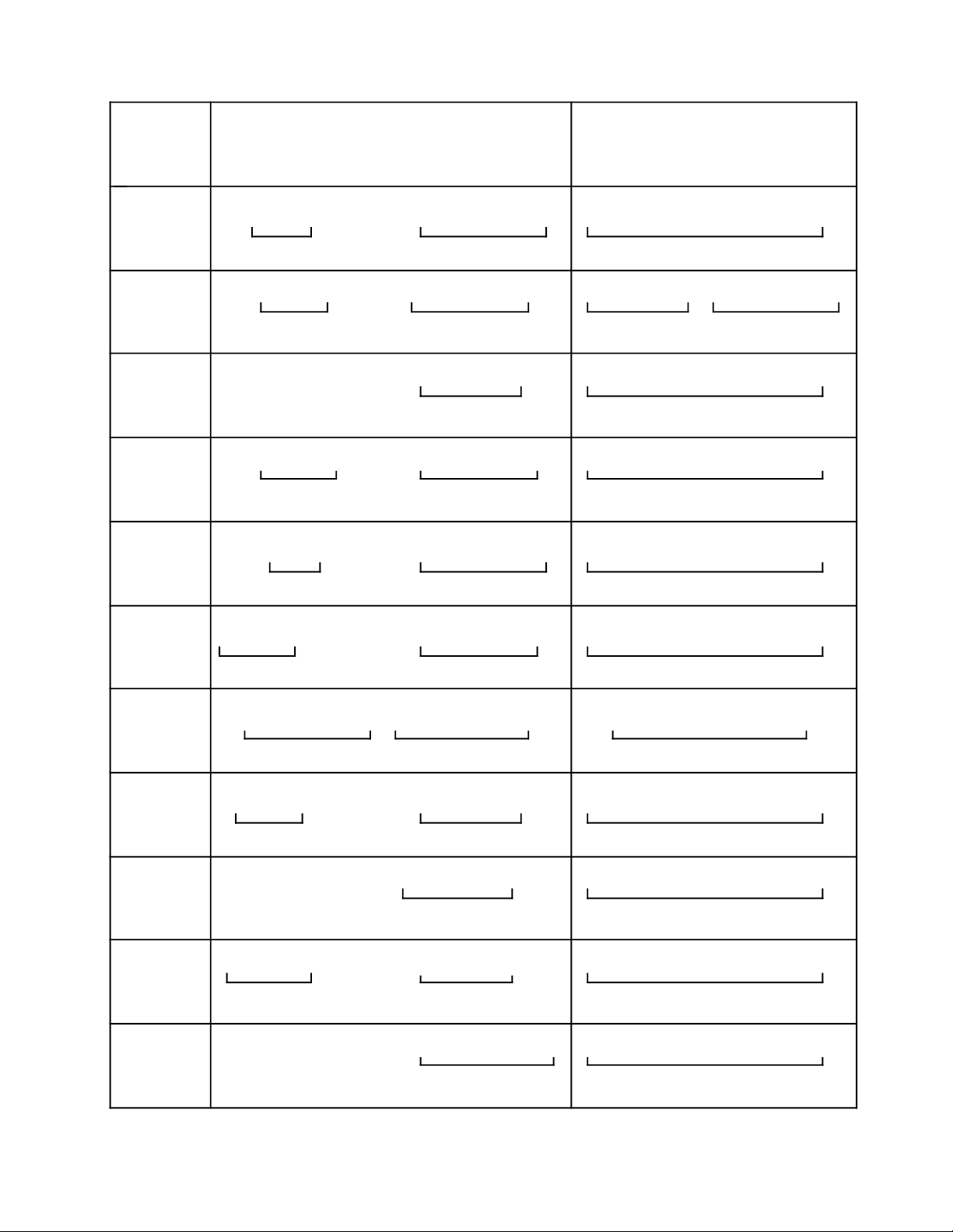
Casio TV Model
Casio Color TV Channel Country Scanning fs(audio)-fv(video) Color burst Notes
Model System System line
A NTSC M/M JPN Japan 525 4.5MHz 3.58MHz
B NTSC M/M US American Samoa / Antigua and Barbuda / Bahamas / Barbados / 525 4.5MHz 3.58MHz
C PAL B/G,H CCIR Afghanistan / Algeria / Austria / Bahrain / Bangladesh / Belgium / 625 5.5MHz 4.43MHz
D PAL -/I UK Hong Kong / UK 625 6 MHz 4.43MHz
E PAL D/I China/UK Democratic People's Republic of Korea / China / Hong Kong 625 6.5 MHz / 6 MHz 4.43MHz
F PAL/SECAM B/G,H CCIR Cyprus / East Germany / Egypt / Greece / Iran / Iraq / Lebanon / 625 5.5 MHz 4.25/4.40MHZ
G PAL M/M US Brazil / Lao People's Democratic Republic 525 4.5 MHz 3.58MHz
H PAL N/N US Argentina / Paraguay / Uruguay 625 5.5 MHz 3.58MHz
I PAL B/G ITALY Italy / Albania / San Marino 626 5.5 MHz 4.43MHz
J SECAM L/L France France 625 6.5 MHz 4.25/4.40MHz
K NTSC M/M US Canada *plus Casio Model BA 525 4.5 MHz 3.58MHz
L PAL B/G,H CCIR Denmark / Finland / Norway / Sweden *plus Casio Model CA 625 5.5 MHz 4.43MHz
M PAL B/B Australia Australia *plus Casio Model CA 625 5.5 MHz 4.43MHz
N PAL B/G,H CCIR West Germany *plus Casio Model CA 625 5.5 MHz 4.43MHz
P PAL B/G,H,I CCIR/UK Casio Model LA plus DA 625 5.5 MHz / 6MHz 4.43MHz
Q PAL B/G,H,I CCIR/UK Casio Model NA plus DA 625 5.5 MHz / 6MHz 4.43MHz
R PAL B/G,H,I Italy/UK Casio Model IA plus CA plus DA 625 5.5 MHz / 6MHz 4.43MHz
S PAL B/G,H Australia *Australia (except VHF CH 0 and 3-5A) 625 5.5MHz 4.43MHz Selector: I
PAL B/G,H CCIR Casio Model CA 625 5.5MHz
PAL B/G,H ITALY Albania, Italy 625 5.5MHz
PAL B/G,H New Zealand New Zealand (except VHF CH 1) 625 5.5MHz
SECAM B/G,H CCIR Casio Model FA 625 5.5MHz 4.25/4.40MHz
SECAM B/G,H Morocco Morocco (except VHF CH 4 ) 625 5.5MHz
PAL I/I Angora Angora (except VHF CH 1) 625 6.0MHz 4.43MHz Selector: II
PAL I/I Ireland Ireland (except VHF CH A) 625 6.0MHz
PAL I/I UK Hong Kong, U.K. 625 6.0MHz
PAL I/I South Africa South Africa (except CH 11 and 12) 625 6.0MHz
PAL D/D China China (except UHF CH 57) 625 6.5MHz 4.43MHz Selector: III
PAL D/K O.I.R.T North Korea, Romania 625 6.5MHz
SECAM K1/- F.O.T. Benin, Burkina Faso, Brundi, Chad, Congo, Cote D'ivoire, Djibouti, 625 6.5MHz 4.25/4.40MHz
SECAM D/K O.I.R.T Bulgaria Czechoslovakia, Hungary, Mongolia, Poland, U.S.S.R., 625 6.5MHz 4.25/4.40MHz
V PAL M/M US System Selector M: BRAZIL, LAOS 525 4.5MHz 3.58MHz Selector: M
PAL N/N US System Selector N: Argentina, Paraguay, Uruguay 625 4.5MHz 3.58MHz Selector: N
W SECAM K1/- F.O.T. Benin, Burkina Faso, Brundi, Chad, Congo, Cote D'ivoire, Djibouti, 625 6.5MHz 4.25/4.40MHz
SECAM D/K O.I.R.T Bulgaria Czechoslovakia, Hungary, Mongolia, Poland, U.S.S.R., 625 6.5MHz 4.25/4.40MHz
Y PAL B/G,H Australia *Australia (except VHF CH 3-5A) 625 5.5MHz 4.43MHz Selector: I
PAL B/G,H CCIR Casio Model CA 625 5.5MHz
PAL B/G,H Italy Albania, Italy 625 5.5MHz
PAL B/G,H New Zealand New Zea land (except VHF CH 1) 625 5.5MHz
SECAM B/G,H CCIR Casio Model FA 625 5.5MHz 4.25/4.40MHz
SECAM B/G,H Morocco Morocco (except VHF CH 4 and 5 ) 625 5.5MHz
PAL I/I Angora Angora (except VHF CH 1) 625 6.0MHz 4.43MHz Selector: II
PAL I/I Ireland Ireland 625 6.0MHz
PAL I/I UK Hong Kong, U.K. 625 6.0MHz
PAL I/I South Africa South Africa (except CH 11 and 13) 625 6.0MHz
SECAM L/L France France (except CH A) 625 6.5MHz 4.25/4.40MHz Selector: III
Belize / Bermuda / Bolivia /Cambodia / Chile / Colombia /
Costa Rica / Cuba / Dominican Republic / Ecuador / El Salvador /
Guatemala / Haiti / Honduras / Jamaica / Mexico / Micronesia /
Netherlands Antilles / Nicaragua / Panama / Peru / Philippines /
Puerto Rico / Saint Christopher & Nevis / Saint Lucia /
South Korea / Surinam / Taiwan / Trinidad and Tobago /
Union of Myanmar / U.S.A. / Venezuela
Brunei / Central African Republic / Equatorial Guinea / Ethiopia /
Ghana /Greenland / Holland / Iceland / India / Indonesia /
Jordan / Kenya / Kuwait / Liberia / Luxembourg / Malaysia /
Maldives / Malta / Mozambique / New Zealand / Nigeria / Oman /
Pakistan / Portugal / Qatar / Seychelles / Sierra Leone /
Singapore / Spain / Pakistan / Portugal / Qatar / Seychelles /
Sierra Leone / Singapore / Spain / Sri Lanka / Sudan / Swaziland /
Switzerland / Tanzania / Thailand / The Yemen Arab Republic /
Turkey / United Arab Emirates / Yugoslavia / Zambia
*Australia (except VHF CH 3-5A)
Libya / Mauritania / Mauritius / Morocco / Saudi Arabia / Syria /
Tunisia / Uganda / Vietnam / Zimbabwe
* plus Casio Model CA
Gabon, Guadeloupe, Guiana, Guinea, Guyana, Ivory Coast,
Madagascar, Mali, Martinique, New Caledonia, Niger, Polynesia,
Reunion, ST. Pierre et Miquelon, Senegal, Tahiti, Togo, Zaire,
Vietnam
Gabon, Guadeloupe, Guiana, Guinea, Guyana, Ivory Coast,
Madagascar, Mali, Martinique, New Caledonia, Niger, Polynesia,
Reunion, ST. Pierre et Miquelon, Senegal, Tahiti, Togo, Zaire,
Vietnam
-6-
Page 8
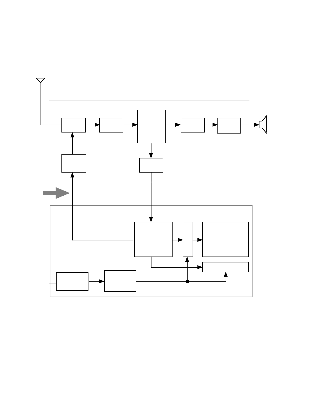
BLOCK DIAGRAM
VHF, UHF
VHF:Abbreviation for VeryHighFrequency.
Thesendingou t ofradiowavesatthe rateof 30 to 300MHz,Producinggoodsoundquality.
UHF:AbbreviationforUltra High Frequency.
Thesendingou t ofradiowavesatthe rateof 300 to3000MHz, Producingexcellentsoundquality.
Antenna
VHF, UHF
Power
Supply
LinearPCB
TU200 Q200
Tuner IF Amp.
Tuning
Voltage
Generator
Display ass'y
IC200
Video Det.
Sound Det.
FMDet.
AFTCircuit
AGCCircuit
Chroma
Circuit
IC700
OSC.
Display Control
A-DConverter
Auto-tuning
Control
VR IC600
Volume
Control
Common
Drive
Audio
Amp.
LCD
Speaker
VR
Brightness
Control
IC800
Display
Voltage
Generator
Segment Drive
Rod Antenna
Whentherodantennaisnotproperlyadjustment, TVreceptio n isnot getaclear picture( picturemovesup ordown,
disappearsperiodically,becomesfuzzy orblurred,isdoubled,etc.). Inthis case, adjustangleanddirection forbest
reception.
LocationswhereTV receptionisbad.
• Far away from broadcastingstations,amongferro-concrete structuresornearmountains.
• Underground,intunnels orinferro-concrete buildings.
• Near high-tension wires, neonsigns, orradiostationswhose frequenciesinterfere.
• Near railroads, highways or airport.
• In trains or cars.
-7-
Page 9

Under poor reception conditions,the tuning indicator may continue to move without stoppingbecause the auto tuner
cannot detect weak broadcasts.In this case, usea commercially available externalantenna or relocate the TV to a
place where reception is better.
The user usually damaged the rod antenna. We suggest that you stock this parts.
Model CV-1 is used both as a earphone and an antenna.
PCB Ass'y
Linear PCB
1) Colortuner: TU200
Selects a desired radio wave and changes it to the videoIF signal.
2) Video IF Amp.:Q200
Amplifies the video IF signal output from the tuner by 10 times.
3) Video Det./ SoundDet./ FM Det./ AFT/ AGC: IC200
Eliminates the carrier wave in the video IFsignal, andpick up the video signal and thesound signal.
Also, the sound signal is pickedup from the sound IF signal by FM detection. Automatic fine tuning circuit for
keeping thefrequency of the oscillator in thetuner correct for bestcolor picture bycompensating for drift and
incorrect tuning. Automatic gain control circuitfor avoiding influence of receiving deterioration by wave
strength.
4) Audio Amp.: IC600
Soundamplification.
5) Chroma Circuit: IC300
Generates the tricolor (red,green and blue) from the video signal.
6) Tuning voltage generator: IC500
Generates the tuning voltage from thetuning pulse(TU).
PW PCB: Generates the power supply voltage.
SUB PCB: Generates thepower supply voltage.
RD PCB: Selects adesired radio wave.
Display Ass'y
LCD
Casio LCD television is used two type of LCD drivesystems: HQM and Active matrix.
1) HQM ( SimpleMatrix )
Scanning and segment transparent electrodes are arranged in closed way. To the scanning electrodes,the gate
pulse is applied timesharing. The TVsignal is changed into 4-bit or 3-bit data through A/D conversion (IC700), so
that the TV signalcan be handed with the LSI, and applied to thesegment electrodes.
Structure is simple and price is low, but contrast ratio is low.
2)Active Matrix
Each picture element electrode is controlled by a transistor. To the gate electrodes, thegate pulse is applied
timesharing, like the HQM. I f the gate pulse is applied, the transistors are in operation and voltage is applied
between thepicture electrodes and common electrodes and the liquid crystal reacts allowing the light to transmit.
Structure is complicated and price is high,but contrastratio is high.
-8-
Page 10
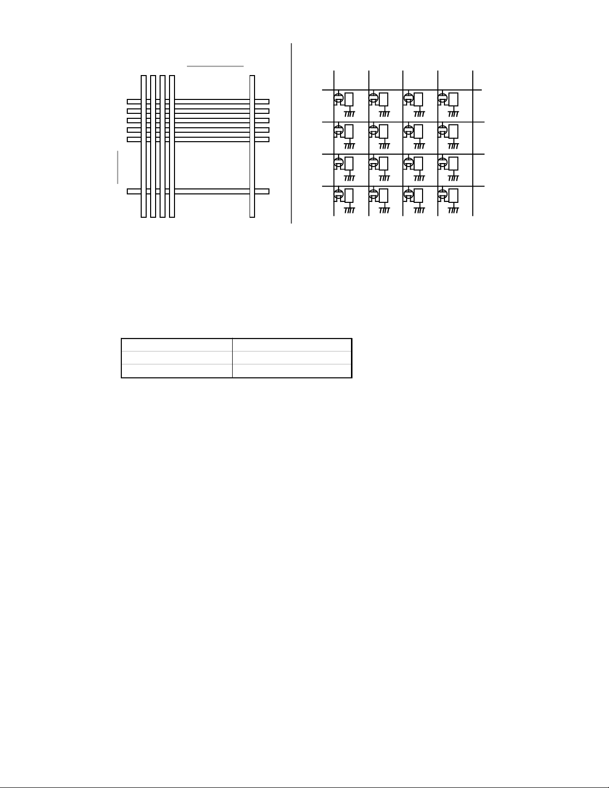
(1) High Quality Matrix
Y1 Y2Y3 Y4 Xn
X1
X2
X3
X4
X5
(2) Active Matrix
Y1 Y2 Y3 Y4
X1
X2
X3
X
n
X4
Back Light: It produceslight and allows the LCD to be seen.
A fluorescent lamp is used this back light, and the life of this unit is to be 1,500 hours.
Power Supply: 3-way power supply system.
Batteries - AA-size or AAA-size (CV-1) dry batteries.
Battery Life:
Type Life
AlkalineLR6 (AM-3) Approx.2 ~3hours
ManganeseR6(UM-3) Approx.15 ~30minutes
AD PCB
1) OSC/ A-D Converter/Display Control/ Auto-Tuning Control: IC700
Converts the color signal into a digital signal. Also, generates the clock pulse for the display and controls the display.
2) Displayvoltage generator: IC800
Generates thedisplay voltage.
Back Light
Placed it under the LCD unitand producing light that TV screen can be seen. A fluorescent lamp is used this back light.
The life is to be 1,500 hours. Newtype of fluorescent lampis to be 3,000 hours. The back light is consumption items,
so even under guarantee replace it under charge basis.
Power Supply
There are 3-way power supply systems.
1) Batteries: AAA-size and AA-size (CV-1)
We recommendto use alkaline batteries.The battery life is approx. 2 to 3 hours with alkaline battery, 15 to30 minutes
with manganese battery.
The battery supplied with TV are test battery which have a shorter life span.
Low battery power generates heat. Heatdoes not mean malfunction.
2)AC adaptor
There are three typeof AC adaptors: 6V, 9V and 12V. The optional AC adaptoris supplied from our sales department.
3)Car adaptor
There are three typeof Car adaptors: 6V, 9V and 12V. The optional car adaptor is supplied from our sales department.
-9-
Page 11

DC IN: External power source jack. Insert the plug of the AC adaptor or the car adaptorinto this jack.
EXT/ANT.: External antenna jack.Insert the plug of theoptional car antenna intothis jack. Connect the optional antenna
adaptorAS-35S to your outdoor antenna or the optional RF cord CF-13 to your VCR.
AUDIO/VIDEO: Audio video jack. Connect the optional Audiovideo cable cord AV-C1 to your VCR.
-10-
Page 12

Tuner
CIRCUIT OPERATION
Thetunerselects andamplifies t heincomingAMvideo-modulated andFMsound-modulatedsignalsand
concertsthemtothe intermediate-frequencysignals required by th e IFamplifiers.
Picturecarrier
Antenna
fv
Amplifythechannel
frequencies
Convertthe channelfrequenciestointermediatefrequencies
PictureIF= fosc -fv = 45.75MHz(USchannel)
Sound IF=
fosc-fs =41.25MHz(USchannel)
Input
Circuit
RFAmp.
Selectspecificchannel
Powersupply
voltage
fs
Soundcarrier
BV
BU
BM
AGC
The Automatic Gain Control system
maintainsasubstantially constant
videodetectorpicture outputby
applyinganautomatically varying dc
biasvoltagetothe RF.Inbasic
principle,the AGCsystem in aTV
receiverissimilar toAVC systems
in radioreceivers-itprovidesa
constant-amplitudesignal.
Field-strength is weak
Tuning
Circuit
Local
oscillator
BS
VHFlow andhigh
channelsselecting
voltage.
VHF(L):
Approx.20V
VHF(H):
Approx.0V
Mixing
Circuit
VIF
SIF
fosc
Localoscillatorfrequency
Tuningvoltageinput terminal.A channel
BT
corresponding to the direct voltage to this
terminalisselected,andfrequency
conversionisperformed.
TV-100B TV-100C
VHF(L) 2CH 1.0-2.8(V) 2CH 1.3-3.3(V)
VHF(L) 6CH 17.2-18.8(V) 4CH 6.5-8.5(V)
VHF(H) 7CH 6.4-8.4(V) 5CH 6.1-8.1(V)
VHF(H) 13CH 17.2-18.8(V) 12CH 17.2-18.8(V)
UHF 14CH 1.0-3.4(V) 21CH 0.9-2.3(V)
UHF 69CH 22.4-23.6(V) 69CH 24.4-25.6(V)
Field-strengthis strong
Tuner
AGC for
Tuner
AGC voltage
Video IF
Amp.
AGC for
IF
AGC
Amp.
AGC voltage
Video
DET
AGC DET
Video
Amp.
Noise
elimination
TunerVoltage
BV: Powervoltageforinner VHFcircuit.
BU:Powervoltage for innerUHFcircuit.
BM:Powersupply forinternalmixer.
VHF(L) VHF(H) UHF
BV Approx. 4V Approx. 4V 0V
BU 0V 0V Approx. 4V
BM Approx. 4V Approx.4V Approx.4V
BT 0 - 25V 0 - 25V 0 - 25V
BS Approx.20V 0V 0V
AGC 1.0 - 3.0V 1.0 - 3.0V 1. 0 - 3.0V
-11-
Page 13

IC200 Video DET., Sound DET., FM DET., AGC, MUTE.
Eliminatesthecarrierwavein the video IF signal, and picks up the videosignalandthe soundIF signal.
Alsothe soundsignalis pickedup fromthesoundIF signal byF Mdetection andcontrolled itsvolumeb y
MUTEvoltage.
Video signal+Sound IF
SIFtrap
ToIC300
SIFtrapremoves
the soundIF.
Discriminator
Picksupthesoundsignal.
SYNC.
SEP
Picksup the synchronizing
pulsefromthevideoIFsignal.
IFAGC
DET.
RF AGC
AGC
The Automatic Gain Control system
maintainsasubstantially constant
videodetectorpicture outputby
applyinganautomatically varying dc
biasvoltagetothe RF.Inbasic
principle,the AGCsystem in aTV
receiverissimilar toAVC systems
in radioreceivers-itprovidesa
constant-amplitudesignal.
Automatic fi n e tuning
AFTblockgenerates th e AFTvoltage
(directvoltage)withadifference of
frequencybetweenth eIFandinput
signalfromthetuner.
Audio Signal
Video Amplifier
Sound Takeoff
Video
DET.
1stand
2nd AMP.
IF signal input
VIF
SIF
Model AFTvoltage
TV-100 2.5+/-0.2V
TV-480 1.7+/-0.2V
SIFfilter
AFT
FM
DET.
Sound
signal
Video
ATT
AMP.
Limiter
SIF
SIFfilter picksupthe
SIF fromvideosignal.
Video detection
Demodulation
Coil connectedt o pinn o.
1 9 and 20 determines
the tuning point of the
LLD detection, and must
b e matched with the
intermediatefrequency.
SIFfilter removesthefs-fvMHzsound
componentfromsound IFsignal.
Buffer
Carrier wave
Videosignal
SoundIF
Limiter-Amplifier
Picksup the soundsignal
fromFMmodulated signal.
U.S.A CCIR U.K. China
SIFfilter 4.5MHz 5.5MHz 6.0MHz 6.5MHz
Discriminator 4.5MHz 5.5MHz 6.0MHz 6.5MHz
SIFtrap 4.5MHz 5.5MHz 6.0MHz 6.5MHz
FMdetection
(Discriminator)
-12-
Limitstheamplitudeof itsoutputsignal to
somepredeterminedthre shol d level.
Thesound iscutoffduring
tuning.Audiosignal iscut
whenpinno. 14 receives
GNDlevel.
ATT
Audio Amplifier
Page 14

IC300 Chroma Circuit (NTSC)
Generatesthetricolorof red,greenandbluefrom the videosignal.
Y/CSeparator
Color
Videosignal
Band pass Amp.
sub carrier
Trap
isthe amplified
compositecolor
videosignal.
Band pass
filter
Color
adjust
Colorsignal
BurstAmp.separates the color
syncfrom the compositevideo
signal.
Color
adjust
Band
Amp.
Burst
Amp.
Luminancesignal
Hueadjust
Contrastadjust
Contrast
Adjust
B-Ydemodulation
Ymixer
BAmp.
Blue
Sync
signal
Burst
Hue
adjust
G-Y
Matrix
Ymixer
GAmp.
Generator
Automatic
Chroma
Control
Color
Killer
Automatic
Phase
Control
R-Y demodulation
Subcarrier
OSC
Ymixer
RAmp.
Automatic Chroma Control
ACCistoprovideautomatic gain control
for the chroma amplifies.This circuitis
keepingthechromaand burstsignalsa ta
constantlevel.
Color Killer
The color killer keepsthe
band pass amplifiercutoffin
APC
Reinsertsasubcarriersignalwith
exactlythecorrectphaseand
frequencybysynchronizingwith
thetransmittedcolor-burstsignal.
the absenceof acolor signal.
DEMODULATION
The B-YandR-Ydemodulators areeach synchronized essentiallyto sampleth e resultant chrominance
signalECand producetherespectiveB-Yand R-Yvoltage.Afterdemodulation, theB-Yand R-Y signals
enterthematrixstage.The twocolorsignalscombinein the G-Ymatrixwhichproduces th e resultantG-Y
colorsignal,andoutput signals (B-Y, R-Yand G-Y) combinewiththe luminancesignalatthe mixer , then
outputsproportionalvalues ofred,blue, andgreen.
Green
Red
-13-
Page 15

IC300 Chroma Circuit (PAL)
Generatesthetricolorof red,greenandbluefrom the videosignal.
Y/CSeparator
Videosignal
Colorsignal
Chroma
Trap
4.43MHz
Band pass
filter
SYNC
SEP.
Luminancesignal
Contrastadjust
Sync
signal
ACC
ACC
DET
Burst
GP
Killer
Chroma
OUT
0° and
180°
PAL-SW
PIX
CTR
F/F
PIX CLAMP
PAL/SECAMSW
90°
Y-OUT
Contrast
adjust
B Matrix
GMatrix
RMatrix
Blue
B-OUT
Green
G-OUT
Red
R-OUT
R-Y
DEM
B-Y
DEM
Subcarrier
OSC
Phase
Control
Thepointthat NTSC isdifferent from PAL in apart
offrameof bold lines
PAL is basically the same asNTSC.PAL is different from NTSC in the wayof the color signaltransmission.
The phaseofB-Ysignal is fixed90degree.The phaseofR-Ysignalchangesat0and180degreeonevery
horizontalscanningline. Th e 4.43MHz sub carrier is usedtotransmit color information.
-14-
Automatic
Page 16

IC300 Chroma Circuit (PAL/SECAM)
Generatesthetricolorof red,greenandbluefrom the videosignal.
Video
signal
Y/CSeparator
Chroma
Trap
4.43MHz
Band pass
filter
Sync
SEP.
Luminance
signal
Contrast
adjust
Sync
signal
PAL
Bell filter
4.28MHz
ACC
ACC
DET
Burst
GP
Killer
Color
signal
Chroma
OUT
0° and 180°
R-Y
DEM
Horizontalsync
PIX
CTR
PIX CLAMP
F/F
PAL/SECAM SW
90°PAL-SW
B-Y
DEM
Y-OUT
Subcarrier
OSC
Contrast
adjust
BMatrix
GMatrix
RMatrix
Blankingsignal
B-OUT
G-OUT
R-OUT
Automatic
Phase
Control
B-Ysignal
4250000Hz
Blue
Green
Red
R-Y
B-Y
Quadrature
coil4.25MHz
SECAM
Limiter
Gate SW
Onedelay
line
limitsthe
amplitude
direct t o switch(non-delayed signal)
through onedelay line(delayed signal)
line identify
line changeover
interlockswitch
ID
F/F
SECAM
SW
Cleaning
PicksuptheSECAM
colorsignals(B-Y,
R-Y) by FM detectors
Subcarrierfrequency
R-Y signal4406350Hz
4.25MHz
B-Y DEM
R-Y DEM
4.406MHz
Quadrature
coil4.4MHz
ItisdifferenceofSECAM,NTSCand PAL that thefrequencyofR-Y andB-Ysignal aredemodulatedand
transmitted reciprocallyinorderon everyline.
The demodulationofsignalSECAMis separatedfromtwosystems. One system isleddirecttothe linechange
over interlockswitchcircuit, anothersystemisled to the switch circuit throughonedelayline.
Theswitch circuitchangesovert hedelayedsignalof atermscanning lineandnon-delayedsignal, takes out two
colordifferentsignal. Bydetectingin eachFM,R-YandB-Ysignal aregotten.
-15-
Page 17

IC400 Tuning Voltage Generators
IC400 has 3circuits for converting pulses to voltages, selects one of VHF-L, VHF-H or UHF, and causes the tuning
voltage to be output from OUT terminal.
OUT IN
U/V H/L SWon
L L S2,S5
L H S3,S6
H L S1,S4
H H S1,S4
S3
S2
S1
S6
S5
S4
TU SWon
L S7
H S8
BT
S8
S7
Current
Source
UHF
VCC
U/V
UHF / VHF channels
switching signal.
Input 4V with setting
the select switch to
UHF.
BS
GEN.
CODE
CONV.
U/V H/L BS TU Vref
BS
VHF low / high
channels switching
signal.
Approx. 20V when
the indicatoris at
VHF low channel.
TU
H/L
VHF low / high channels switching
Tuning pulse being
output fromIC700.
signal.
GND level when the indicator is VHF
TU pulse BT voltage
low channel.
Approx. 4V when the indicator is
VHF highand UHFchannel
Vref
GEN.
BT
Tuning voltage.
Tuning pulse is converted into a
DC voltage by theIC400, and
applied to the tuning voltage to
the tuner.
U/V H/L BS BT
VHFL GND GND Approx.20V Approx.0 ~20V
VHFH GND Approx.4V GND Approx.0~ 20V
UHF Approx.4V Approx.4V GND Approx.0~20V
When the Up or Down buttons is pressed, TU pulse becomes
gradually narrower, and thetuning voltage BT is also gradually
decreases.
-16-
Page 18

IC700
VSS2 TE1 TE2 TE3 TE4 TE5TE6 M6 M5 M4 M3 M2 M1 AFT
AD2
AD1
B
G
R
RLL
VDD2
RHH
M7
M8
M9
M10
PSi
VSS1
A/D
Mode
Control
Data Output
Test Control Mode Control
Channel
Bar
Control
Vertical
Positioning
Control
Frequency
Divider
Tuning Voltage
UP/DOWN Counter
Pulse Width
Modulation D/A
Horizontal
Positioning
Control
Sweep
Control
Phase
Comparator
Frequency
Divider
AFT
Control
Key
Switch
Control
Mute
Control
Synchronism
Judgment
Frequency
Separator
Oscillator
KDB
KCB
AVB
UHF
MTB
VLB
TU
VDD1
C-S
PD
OSC1
OSC2
D1 D2 D3 D4 D5 D6 CDBCFB CNB ECB SNB SCB STB HDB
SignalName Function SignalName Function
D1~ D6 Displaydata output terminal. VLB VHFHigh/Lowchannel selectsignal
SNB Data latch signal. output.
CDB Scanning startsignal. UHF VHF/UHFselectsignal.
CFB Voltage changeover signal. AVB Keyinput.
CNB Scanning Signal shiftlock signal. KCB Key input.
SCB Brightnessmodulationpulse control. KDB Keyinput.
STB Sampling startsignal. AFT AFT voltage input terminal.
ECB
CK1,CK2
OSC1,OSC2 Oscillatorcontrolterminal. RLL Low levelvoltageinput terminalof
PD
C-S Sync pulseinput. RHH High levelvoltageinput terminalof
HDB
VDD1 VDD voltage input. PS1 Mode controlsignal.
MTB
TU Tuning controlpulse output.
Controlthe segment drive terminal. M1~M10 Mode select signalinput terminal.
"H" levelduring no display. TE1~ TE6 Test terminal.
Clockpulse output terminal. R,G, B Colorsignal.
Clockpulse adjustmentterminal. video signal.
HorizontalSync signalinput. video signal.
Mute controlterminal. VSS1 Power supplyvoltageinput.
CK1 CK2
-17-
Page 19

Tuning Operation
(NTSC)
UP orDown
button
PD
Oscillator
OSC1,OSC2
Frequency
Divider
Horizontal
Positioning
Control
TO
LCD
Vertical
PositioningControl
IC700
AFT Control
PulseWidth
Modulation
BU
BTGenerator
UHF Tuning
Circuit
UHF Mixing
Circuit
Synchronism
Key Switch
Control
Sweep
Control
Tuning voltage
control
TU
H/L
BSGenerator
Local
Oscillator
VHF Mixing
Circuit
VLB
H/L
IC400
VHFTuning
Circuit
A/D
Convertor
Channel Bar
Control
Mute
Control
IF AMP. SAW Filter
MTB
Data Output
Local
Oscillator
Power Switch
UHF
VHF/UHF
RF AMP.
IF AGC
Judgment
VCC1 Back Light
UHF or
VHF
VHF
BackLight
Circuit
VHF/UHF
InputCircuit
TUNER
IC200
Frequency
Separator
Phase
Comparator
Power Supply
Circuit
Batteriesor AC Adaptor
Antenna
Video DET.AFT
Video AMP. SIF Filter Limiter FM DET ATT
Burst
Generator
3.58MHz Trap
Band pass
Filter
Contrast
Adjust
Band AMP. Burst AMP.
ACC
Color Killer
1stAMP.2nd AMP.
IC300
Color Adjust
HueAdjust
Automatic
PhaseControl
3.58MHzOSC
Buffer AMP.SIF Trap SYNC. SEP
B-Y Demodulator
G-YMatrix
R-Y Demodulator
Y Mixer
Blue AMP.
Y Mixer
Green AMP.
Y Mixer
RedAMP.
B
G
R
-18-
Page 20

Adjustment
Casio gives another through adjustment before TVs are put on the market. There's usually no
need for you to adjust the TVs except VCC voltage setting when repaired the power supply
circuit and VCOM adjustment whenever replaced the TFT LCD.
The other adjustments, it is necessary to have the expensive equipment's. When appropriate
equipment's are not available, we recommend to replace the Linear PCB ass'y.
The full details of adjustments, refer to each of service manuals.
Main Adjustment Points Outline Equipment
VCC Voltage Setting Set the voltage VCC. If set value is wrong, Power supply
malfunction or increasing consumed current. Voltmeter
Be sure to adjust it.
Video Detection Coil Adjustment No reception is possible at all or the sensitivity is Power supply
extremely bad when replaced IC200 or video det- Pattern generator
ection coil, be sure to adjust the video detection Signal generator
coil. Oscilloscope
Low-pass filter
AFT Coil Adjustment No reception is possible at all or the sensitivity is Power supply
extremely bad when replaced IC200 or AFT coil, Pattern generator
be sure to adjust the AFT coil. Signal generator
Oscilloscope
Voltmeter
PD Voltage Adjustment No synchronization is gained. Power supply
Pattern generator
Signal generator
Voltmeter
IF levelmeter
Contrast Adjustment Make this adjustment when contrast is not good. Power supply
Pattern generator
Signal generator
Oscilloscope
Tint Volume Adjustment When replacing IC300 or tint volume, be sure Power supply
to adjust the tint volume. Pattern generator
Signal generator
Oscilloscope
AGC Adjustment No reception is possible at all or the sensitivity is Power supply
extremely bad when replaced T200 or IC200, be Pattern generator
sure to adjust the video detection coil. Signal generator
Oscilloscope
IF levelmeter
Free-Running Frequency No synchronization is gained. Power supply
Adjustment Frequency Counter
VCOM Adjustment Make this adjustment whenever replacing the Power supply
(TFT LCD only) LCD or when the LCD is flickered. Pattern generator
Signal generator
Oscilloscope
Photo diode
-19-
Page 21

1. No power
Check fuse.
Is fuseblown up?
NO
TROUBLESHOOTING
YES
Replace fuse.
Measure output
voltage of DC-DC
convertor.
Is voltage
VCC2 +4V
DC?
NO
YES
• Replace LCD unit.
• Replace inverter transformer or
transistor(s) on power supply for
back light.
• Replace coil and capacitor on
power supply for back light.
A
• Check power switch.
• Check poorsoldering on
power supply block.
Is itOK?
NO
YES
• Replace all of transistor Q100,
Q101 andQ102 on power
supply block.
• Replace DC-DC convertor.
Replace power
switch or resolder.
-20-
Page 22

2. Sound heard, but no picture
Check temperature fuse.
Is fuse
blown up?
NO
YES
Replace
fluorescent
lamp.
Is apicture
OK?
YES
NO
• Check poorsoldering on
power supply for back light.
• Replace Inverter transformer
or transistor(s) on power
supply for back light
Replace fuse.
END
3. Picture all green
Replace LCD
unit.
Is apicture
OK?
NO
A
YES
END
-21-
Page 23

4. No picture and high current consumption.
Burning a transistor(s) on power supply.
Replace DC-DC
convertor
Are pictureand
current
consumption
OK?
YES
NO
Replace allof transistor
on power supply block.
5. Picture all green and high current consumption.
Burning a transistor(s) on power supply for back light.
Replace inverter
transformer.
END
Are pictureand
current
consumption
OK?
NO
• Replace all of transistor
on power supply for back
light.
• Replace Coil and capacitor
on power supply for back
light.
YES
END
-22-
Page 24

6. No sound
Measure the
audio signal.
Does the audio
signal output of
audio amp.?
NO
YES
Check the wire of
•
speaker.
Replace speaker.
•
Does the audio
signal appear at
IC200(AUDIO)?
• Check the soldering around IC200.
• Replace IC200.
7. A certain button does not function
Check the switch.
pin 13of
NO
YES
• Check the soldering
around audio amp.
• Replace audio amp.
Is switch
defective?
NO
• Check the soldering around
switch.
• Check the circuit between
IC700 and switch.
• Replace IC700.
-23-
YES
Replace the
switch.
Page 25

8. Automatic tuning doesn't stop.
collector waveform
20µs
Varies between
20 to 50mV
Measure the
of IF amp.
120mV
Figure 1
Is the
waveform like
that shownin
Fig. 1?
NO
Are BM,BV
and BU of
tuner voltage
4V?
YES
Check BS of tuner
voltage ina channel of
L andH of VHF.
YES
NO
B
• Check the circuit between
switch and tuner.
• Replace switch.
Is BSvoltage
21V at VHF L
channel?
YES
Is BSvoltage
GND level at
VHF H
channel?
YES
-24-
NO
NO
Check the voltage at pin
no. 10 (H/L) of MSC1169.
DC
Page 26

B
Replace IC200.
YES
Is the waveform at
pin no. 18 of IC200
like that shown in
Fig. 2 when the
indicator passes
the receiving
YES
Is AFT(at pin no.
17 of IC200)
voltage 0to 4V
While Indicator
moves?
YES
20µs
0.5V
NO
Figure 2
NO
20µs
2V
Figure 4
Is the waveform
at pin 19 and 20
of IC200 like that
shown Fig.3?
Replace IC200.
20µs
10mV
NO
Figure 3
• Check the poor
soldering on all
line of IC200 and
MSC1169.
• Replace IC200.
Varies between
20 to 50mV
Is SyOUT(at pin
no. 23 of IC200)
like that shown
Fig. 4?
YES
Is the waveform of R,
G andB like that
Fig. 5 when the
indicator passes the
receiving channel ?
0.1µs
YES
E
0.2V
NO
20µs
0.5V
NO
Figure 6
Figure 5
Replace IC200.
Is anAV jack
OK?
NO
Replace AVjack.
-25-
YES
Replace H300.
NO
Is the
waveform
of H300 like
that shown
Fig. 6?
YES
• Check the circuit between
IC200 andIC300.
• ReplaceIC300.
Page 27

C
Check BT of tuner
voltage ina
channel of VHF.
Is BT voltage
0 to 21V at
VHF channel?
YES
Is the tuner
voltage AGC
1.0 to 1.2V?
NO
NO
5µs
1V
Replace IC200.
Figure 7
Is the waveform
at pin no. 11(TU)
of MSC1169 like
that shownin Fig.7?
NO
YES
Replace MSC1169.
YES
Does 4Vappear
at pin no. 9(H/L) of
MSC1169 at
UHF?
NO
YES
Replace tuner.
• Check the circuit
between MSC1169
and IC700.
• Replace IC700.
.• Check the circuit between
switch andMSC1169.
• Replace Switch.
-26-
Page 28

D
IS H/L 4V
at VHF L channel?
NO
IS H/L voltage
GND level at
VHF H channel?
NO
• Check the circuit between
MSC1169 andIC700.
• Replace IC700.
YES
YES
Replace MSC1169.
Check the circuit
between IC300and
IC700.
NO
E
YES
Do C-S,AFT
and R-G-B
pulse appear
on IC700?
YES
50ns
5V
Figure 8
Check the poor
•
soldering on
OSC b lock.
Replace IC700.
•
-27-
NO
Is the waveform
at pin no. 17of
IC700 (OSC)like
that shownin
Fig. 8?
YES
Replace LCDunit.
Page 29

Trouble example
TV-7
No picture FL replaced
No sound Battery replaced
No tuning Battery replaced
TV-100
No picture FL replaced
No sound Battery replaced
Bright volume doesn't work Defective R825
Picture all green Short circuit joint on lead of capacitor C105
Indicator does not stop Poor soldering joint on lead of capacitor C303
No tuning when the RF signal is Defective IC200
under 55dBµ
Tuning is OK, but erratic display Defective capacitor C205 & C808
Indicator does not stop Defective capacitor C205 & C808
when the RF signal is strong
Symptoms Causes
Temperature fuse replaced
Power switch replaced
Fuse replaced
Battery replaced
Defective speaker
Symptoms Causes
LCD replaced
DC jack replaced
Fuse replaced
Poor soldering
Speaker replaced
Poor soldering on IC
Poor soldering joint on terminal pin 17 of IC700
Broken resistor R703
Defective capacitor C205 & C808
Defective F200
TV-160
Symptoms Causes
No picture Fuse replaced
Battery replaced
LCD replaced
No sound Speaker replaced
Indicator does not stop Battery replaced
LCD replaced
Specific channel does Speaker replaced
not receive LCD replaced
Speaker replaced
Poor reception or LCD replaced
picture dark FL replaced
-28-
Page 30

SCHEMATIC DIAGRAM & WAVEFORMS
AV Jack
Power
Jack
Batteries
NTSC
EXT
Jack
Power supply
circuit
Fuse
Antenna
TUNER
BU
UHF input
circuit
ANT
VHF input
circuit
Power
switch
BU(4V)
BV(4V)
U/V
IC300
Croma circuit
FSC APC ACC TINT
APC
VCO
VXOUT
7
VXOF Killer F KO YIN PIX
X'tal
UHF RF
Amp.
VHF RF
Amp.
BV
UHF tuning
circuit
VHF tuning
circuit
VHF local
oscillator
AGC 1.0‘ 3.0V
IC400
Tuning voltage generator
AMP.
S3
S2
S1
S6
S5
S4
CODE
CONV.
TINT
AMP.
U/V H/L SW ON
L L S2, S5
L H S3, S6
H L S1, S4
H H S1, S4
H/L
CIN G
ACC
Color
BURST
GATE
KILLER
BS
GEN.
S7
BS
12
11
OUT
S8
TU
R-Y
DET.
PIX
8
UHF local
oscillator
UHF mixing
circuit
VHF mixing
circuit
IN
TU SW ON
L S7
H S8
Vref
GEN.
Vref
R
MATRIX
(CONTRAST)
G-Y
DET.
Cont
VCC2
Current
Source
CLAMP
Cont OUT
10
B
B-Y
DET.
IF output
BS(0/20V)
BT(0‘ 21V)
BT
C-SY
GATE
GEN.
BGPW
9
1
IF Amp.
IC200
Video DET., Sound DET., FM DET., AGC, AFT and Mute
4
5
SYNC.
SAW filter
1
F200
2
IC700 OSC, A-D converter, Display control Auto-Tuning control
VSS2 TE1
A/D
Mode
control
Data Output
D1D2 D3
D4D5D6
TE4 TE6
TE2
TE3
Test control
Channel bar
control
TE5
SEP
IF AGC
DET.
RF AGC
(Forward)
M6 M5 M4 M3 M2 M1 AFT
Mode control
Frequency
divider
Vertical
positioning
control
CDB
CFB
LLDAFT
VIDEO
DET.
Sweep
control
Tuning voltage
Up/Down counter
Pulse width
modulation D/A
Horizontal
positioning
control
CNB
SNB
3
2
SCB
4.5MHz
2nd
AMP.
1st
AMP.
AFT
control
STB
AFT
4.5MHz
VIDEO
AMP.
Phase
comparator
Frequency
divider
FM
DET.
Mute
control
Synchronism
judgment
CK2CK1HDB
4V
FM detection
ATT
LIMITER
Key
switch
control
Frequency
separator
Oscillator
VC
BUFFER
KDB
KCB
AVB
UHF
MTB
VLB
TU
C-S
PD
VDD1
OSC1
OSC2
CDB
CFB
CNB
IC703
6
Amp.
Earphoen
Jack
SIF filter
4.5MHz
STB
CK2CK1
S1 S359
C1
C110
S2 S360
CK1
CK2
STB
Speaker
SNB
LCD
SNB
3V
IC702
D1~D3
D4~D6
IC701
-29-
Page 31

AV Jack
PAL
4.5, 5.5, 6.0 or 6.5MHz
Ceramic discriminator
FM
DET.
VIDEO
AMP.
SIF IN
FM detection
FMD
ATT
LIMITER
6
AUDIOATTSIF OUT
Speaker
Amp.
Earphoen
Jack
BUFFER
SIF filter
4.5, 5.5, 6.0 or 6.5MHz
EXT
Jack
Antenna
BU
ANT
Power
switch
TUNER
UHF input
circuit
VHF input
circuit
BU(4V)
BV(4V)
UHF RF
Amp.
VHF RF
Amp.
BV
UHF tuning
circuit
VHF tuning
circuit
VHF local
oscillator
AGC 1.0‘ 3.0V
UHF local
oscillator
UHF mixing
circuit
VHF mixing
circuit
VCC2
IF output
BS(0/20V)
BT(0‘ 21V)
1
IF Amp.
VHF L 20V
VHF H, UHF 0V
SAW filter
1
2
F200
IC200
4
SYIN
IF AGC
5
SYOUT
4.5, 5.5, 6.0 or 6.5MHz
LLDAFT
LLD
3
2
AFTC
SIF trap
AFT
VIDEO
ADJ
SYNC.
SEP
AFT
VIDEO
DET.
IF AGC
DET.
2nd
AMP.
IF AGC
OUT
IF AGC
IN
RF AGC
(Forward)
RF AGC
IF IN
1st
AMP.
IF IN
Power
Jack
Batteries
Power supply
circuit
Fuse
4.43MHz
IC300
IDF KIL.O
IDENT
PAL/
SECAM SW
B-Y
(S)
CODE
CONV.
Chroma
trap
YIN
KIL.F
KILLER
CW
INV.
PAL-SW 90
C
R-Y
(R-Y)
(S)
IC400
S3
S2
S1
S6
S5
S4
H/LU/V
VHF L 0V
VHF H, UHF 20V
8
PIX
PIX
CTRL
PIX
R-Y
DEM
COUT
AMP.
AMP.
U/V H/L SW ON
L L S2, S5
L H S3, S6
H L S1, S4
H H S1, S4
BS
GEN.
11
CIN
COLOR
Y-OUT
CLAMP
B-Y
DEM
C
VXOF X'TAL VXO
(B-Y)
S8
S7
BS
12
SYNC
SEP.
G-OUT R-OUT
G MATRIX
CHROMA
OUT
VCO
7
INOUT
TU SW ON
L S7
H S8
Current
Source
Vref
GEN.
Vref
TU
G
R
R MATRIX
ACC
APC
FSC APC ACC BCC
OUT
10
CONT
B
OUT
B-OUT
B MATRIX
ACC
DET.
BT
HD CONT
C-SY
F/F
CONT
RASR
CTRL
BGP
9
BGPW
IC700
VSS2 TE1
Mode
control
A/D
D1D2 D3
TE2
Test control
Data Output
D4D5D6
TE4
TE3
Channel bar
control
TE6
M6 M5 M4 M3 M2 M1 AFT
TE5
Mode control
Frequency
divider
Sweep
control
Tuning voltage
Up/Down counter
Pulse width
modulation D/A
Horizontal
positioning
control
CDB
Vertical
positioning
control
CNB
SNB
CFB
SCB
STB
AFT
control
HDB
Phase
comparator
Frequency
divider
Mute
control
Synchronism
judgment
CK2CK1
4V
Key
switch
control
Frequency
separator
Oscillator
VC
KDB
KCB
AVB
UHF
MTB
VLB
TU
C-S
PD
VDD1
OSC1
OSC2
CDB
CFB
CNB
IC703
STB
CK2CK1
S1 S359
C1
C110
S2 S360
CK1
CK2
STB
SNB
LCD
SNB
3V
IC702
D1~D3
D4~D6
IC701
-30-
Page 32

SECAM
Power
Jack
Batteries
EXT
Jack
Power supply
circuit
Fuse
Antenna
BU
ANT
Power
switch
BU(4V)
BV(4V)
4.43MHz
IC300 (PAL)
IDF KIL.O KIL.F
PAL/
SECAM SW
B-Y
(S)
TUNER
UHF input
circuit
VHF input
circuit
Chroma
trap
KILLER
IDENT
CW
INV.
R-Y
(S)
UHF RF
Amp.
VHF RF
Amp.
IC500
AMP.
S3
S2
S1
S6
S5
S4
CODE
CONV.
H/LU/V
VHF L 0V
VHF H, UHF 20V
8
YIN
PIX
PIX
CTRL
PIX
PAL-SW 90
R-Y
DEM
C-
C
OUT
(R-Y)
BV
AGC 1.0‘ 3.0V
AMP.
U/V H/L SW ON
L L S2, S5
L H S3, S6
H L S1, S4
H H S1, S4
BS
GEN.
11
CIN
COLOR
Y-OUT
CLAMP
B-Y
DEM
C
VXOF X'TAL VXO
(B-Y)
UHF tuning
circuit
VHF tuning
circuit
VHF local
oscillator
S8
S7
BS
12
SYNC
SEP.
G-OUT R-OUT
G MATRIX
CHROMA
OUT
VCO
7
UHF local
oscillator
UHF mixing
circuit
VHF mixing
circuit
VCC2
INOUT
TU SW ON
L S7
H S8
Current
Vref
GEN.
TU
G
OUT
Source
Vref
R
R MATRIX
ACC
APC
FSC APC ACC BCC
10
CONT
B
OUT
B-OUT
B MATRIX
ACC
DET.
IF output
BS(0/20V)
BT(0‘ 21V)
BT
HD
F/F
1
IF Amp.
C-SY
CONT
RASR
CTRL
BGP
9
SAW filter
1
2
VHF L 20V
VHF H, UHF 0V
CONT
BGPW
F200
5.5 or 6.5MHz
Ceramic discriminator
FM
DET.
VIDEO
AMP.
FM detection
FMD
ATT
AV Jack
AUDIOATTSIF OUT
Amp.
6
Speaker
BUFFER
LLDAFT
LLD
5.5 or 6.5MHz
3
2
VIDEO
2nd
AMP.
SIF trap
AFT
AFT
4
IC200
IF AGC
ADJ
SYOUT
IF AGC
DET.
5
SYIN
SYNC.
SEP
AFTC
VIDEO
DET.
Earphoen
IF AGC
OUT
RF AGC
(Forward)
IF AGC
IN
Quadrature
coil 4.25MHz
RF AGC
IF IN
IC700
1st
AMP.
IF IN
VSS2 TE1
A/D
Mode
control
Data Output
D1D2 D3
TE2
TE3
Test control
D4D5D6
SIF IN
TE4
TE6
TE5
Channel bar
control
CDB
LIMITER
M6 M5 M4 M3 M2 M1 AFT
Mode control
Frequency
divider
Tuning voltage
Up/Down counter
Pulse width
modulation D/A
Vertical
positioning
control
CNB
SNB
CFB
AFT
control
Sweep
control
Horizontal
positioning
control
SCB
STB
Frequency
divider
HDB
Jack
SIF filter
5.5 or 6.5MHz
Mute
control
Phase
comparator
CK2CK1
4V
Key
switch
control
Synchronism
judgment
Frequency
separator
Oscillator
VC
KDB
KCB
AVB
UHF
MTB
VLB
TU
C-S
PD
VDD1
OSC1
OSC2
CDB
CFB
CNB
IC703
STB
CK2CK1
S1 S359
C1
C110
S2 S360
CK1
CK2
STB
SNB
LCD
SNB
3V
IC702
D1~D3
D4~D6
IC701
Bell filter
4.28MHz
IC400(SECAM)
One delay
line
B.G.P.
Delay
BGPW C-OUT
SW
BP2
SECAM
CIN
Gate
C-SY
ID
BP1
Limiter ID
Killer
DL CIN
DL CIN
DF4BLKPAL CIN HD
4.25MHz
FF
SECAM
SW
-
+
COLOR
Cleaning
DF1
4.406MHz
Quadrature
coil 4.4MHz
B-Y Det
R-Y Det
DF2 R-Y KIL.F
KIL.OB-YDF3
-31-
Page 33

Waveforms
1
20µs20µs
2
120mV
3 4
10mV
5 6
20µs
20µs20µs
0.5V
20µs
0.2V
2V
7 8
0.2V
0.1µs
-32-
0.5V
20µs
0.1V
Page 34

Waveforms
9 10
2V
20µs20µs
20µs
1211
0.5V
5µs
50mV
1V
-33-
Page 35

CASIO COMPUTER CO., LTD.
SERVICE DIVISION
8-11-10, Nishi-Shinjuku
Shinjuku-ku, Tokyo 160, Japan
Telephone: 03-3347-4926
Printer in Japan
 Loading...