

Page 1
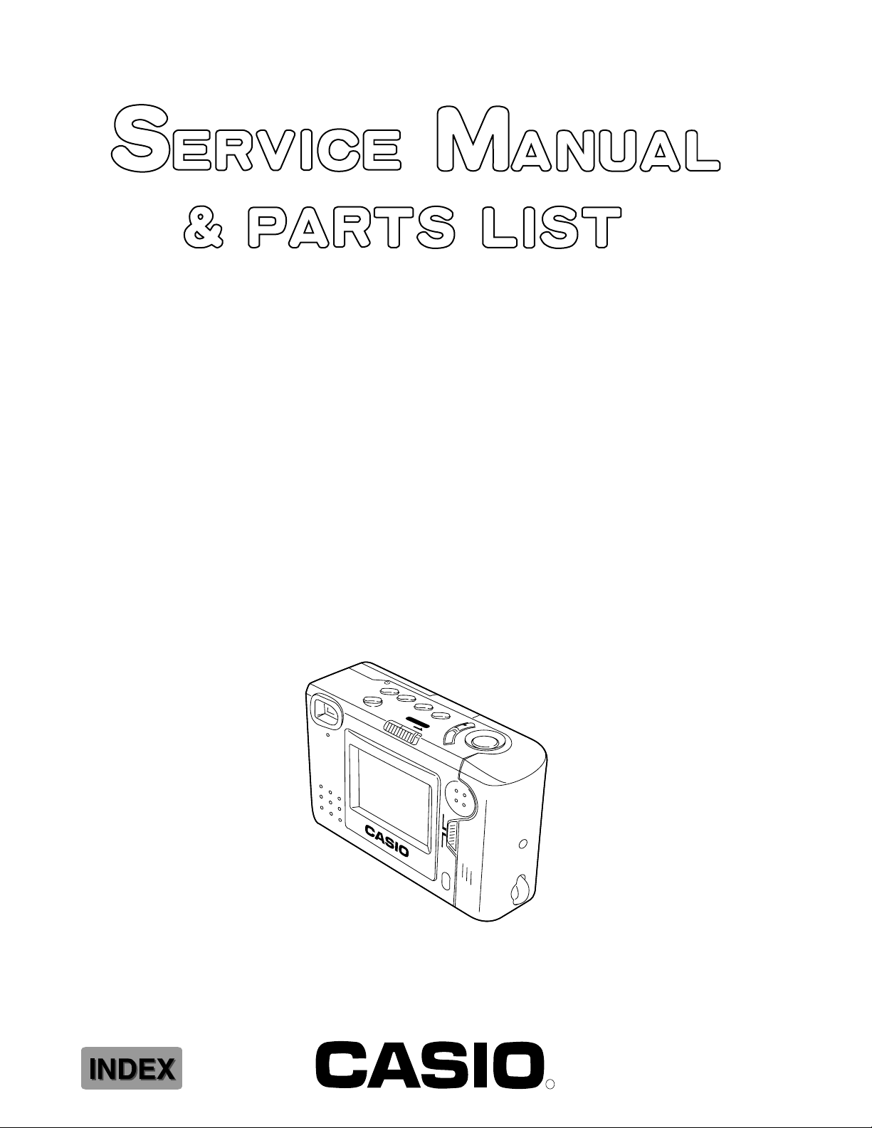
QV-70B(NTSC)
QV-70C(PAL)
(KX-770)
OCT. 1997
(without price)
DEL
/PROTECT ZOOM DISP
POWER
ON/OFF
MODE
+
–
REC
PLAY
LCD
ON/OFF
R
Page 2

CONTENTS
SPECIFICATIONS ......................................................................................... 1
BLOCK DIAGRAM ........................................................................................ 2
COLOR ADJUSTMENT................................................................................. 3
MEMORY RESTORING AND RESET ........................................................... 4
DISASSEMBLY ............................................................................................. 6
ASSEMBLY ................................................................................................... 8
PRINTED CIRCUIT BOARDS ....................................................................... 9
EXPLODED VIEW ....................................................................................... 12
PARTS LIST ................................................................................................ 13
SCHEMATIC DIAGRAMS ........................................................................... 19
WAVEFORMS.............................................................................................. 24
Page 3
SPECIFICATIONS
Item
1. Recording System Digital (JPEG based)
2. Video Signal System NTSC (QV-70B) / PAL (QV-70C)
3. Recording Medium Built-in 2-MB flash memory
4. Number of pages 96
5. Delete Functions Single page; All pages (with page protect feature)
6. Imaging Device 1/5-inch CCD (Total Number of Pixels: 250,000)
7. Lens Fixed focus with macro position; F2.8/f = 5.2 mm
8. Aperture F2.8/F8 manual switching
9. Focal Length F2.8/NORMAL : 0.6 m to 3.0 m
F2.8/MACRO : 12 cm to 14 cm
F8/NORMAL : 0.4 m to ~
F8/MACRO : 10 cm to 18 cm
(from lens protection filter)
10. Light Metering TTL center point by photographic element
11. Exposure Metering Aperture priority AE
12. Exposure Range EV +6 to 18
Specification
13. Exposure Adjustment –2 EV to +2 EV
14. Shutter System Electronic
15. Shutter Speed 1/8 to 1/4000 second
16. White Balance Automatic
17. Self-timer 10-second
18. Monitor 61,380-pixel 1.8-inch TFT low-glare color LCD
19. Terminals DIGITAL; VIDEO OUT; DC IN 6 V
20. Power Supply Batteries (AA-size Alkaline or lithium batteries × 3) /AC Adaptor
21. Current Consumption Approximately 550 mA (REC mode)
22. Dimensions 66(H) × 103(W) × 34(D)mm
23. Weight Approximately 150 g (excluding batteries)
24. Accessories Wirst strap; soft case; video cable;
Alkaline batteries (LR6 × 3)
— 1 —
Page 4
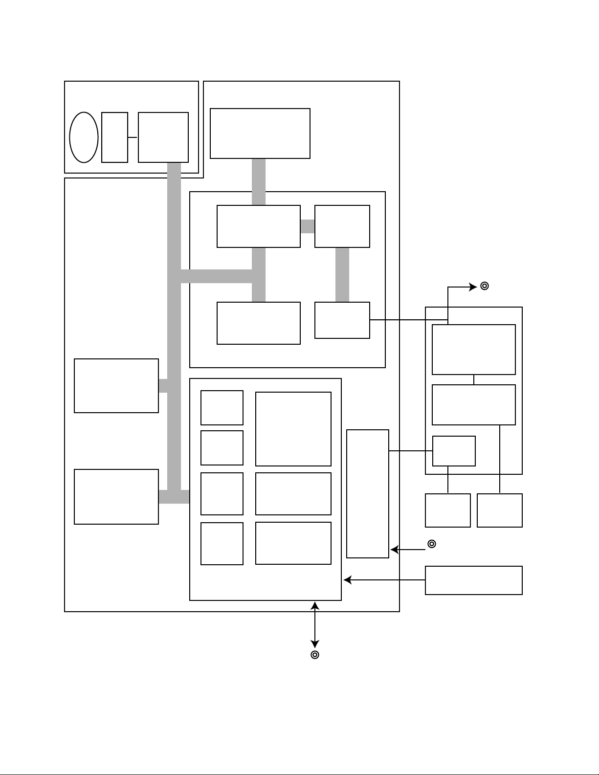
BLOCK DIAGRAM
Camera Unit Digital PCB
IC701
Lens CDD
A/D
converter
HM538123BJ (NTSC)
HM538253BJ (PAL)
2M bit VRAM
IC602
TC5816AFT-1
16M bit
Flash memory
IC601
HM514800CLJ
2M bit DRAM
VRAM
controller
Data
compressor
expander
IC700
HG51B167FB
ROM
RAM
CPU
I/O
port
Direct
memory
access
controller
Bus
state
controller
Serial
communication
interface
Video
encoder
D/A
converter
Power
supply
Video out
Linear PCB
IC300
IR3P90Y1 (NTSC)
IR3Y21 (PAL)
Chroma circuit
IC400
MSM6770CGS
Display controller
Power
supply
Back
light
AC Adaptor
Battery
LCD
IC600
HD6437034SK24F (NTSC)
HD6437034AK28F (PAL)
Digital I/O
— 2 —
Key PCB
Page 5
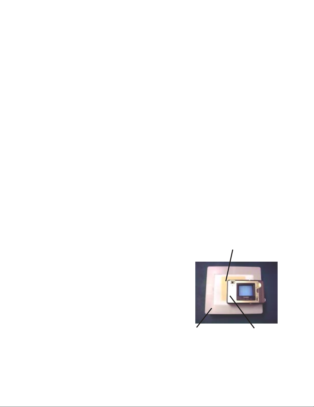
COLOR ADJUSTMENT
THE COLOR ADJUSTMENT IS REQUIRED AFTER THE FOLLOWING SITUATIONS
* The flash memory is initialized by the "AMED-I" command.
* The digital PCB or the camera unit is replaced.
REQUIRED TOOL
Light box: Handy 5000 (Code No.: 1904 5301)
Color filter: LBA 3 (Code No.: 1904 5302)
Color adjustment software: Sdj770vb.exe
Cable for QV-Link
TO DO THE COLOR ADJUSTMENT
1. Connect QV-70 to PC with QV-Link cable.
2. Set the aperture switch of QV-70 to F8.
3. Put the color filter on the light box, and turn the light box on.
4. Put the QV-70 with its lens toward the color filter and light box, and turn the QV-70 on.
5. Execute the color adjustment software "Sdj770vb.exe" on PC (MS-DOS).
Type "Sdj770vb", then press Enter. The message "WAIT" appears on the QV-70 and some parameters
appear on the PC like as the followings.
SUMCODE = 835321
adjust for KX770.
*******************************************
* COLOR ADJUSTMENT for KX770 *
* ver 1.0 *
*******************************************
CAUTION!!! Set f-stop to F8, otherwise doesn't work correctly.
Now adjusting... 0 2
done.
System block 1FE
ASUM 4AB40 CSUM 35662
DSUM 2EA67 ESUM 558FF
RKD FE30 RKE 1D0
BKA 1F0 BKC FE10
GKC 200 GKD 100 GKE FF00
ALPHA FFFC BETA FF82 TINT 155
RAlimit_L BBB RAlimit_H FE0
BAlimit_L 1298 BAlimit_H 1ECE
COL_BAS 28 Y_OFFSET 2
RAMP_INIT DCD BAMP_INIT 18B3
LIN_SUB 108 LIN_SUBY F8
Color filter: LBA 3
Light box: Handy 5000
QV-70
— 3 —
Page 6

MEMORY RESTORING AND RESET
MEMORY ERROR
"Memory error" (#1 ~ #3) message appears on QV-70 camera, when an error is found in its flash memory. In this
case, the QV-70 is locked up and do not accept any operation except power on / off.
MEMORY ERROR #1
When the memory error #1 occures, press the + button to do the error reset. The following display will be appeared on
QV-70.
ERROR RESET
YES SHUTTER
NO CALL TECH
SUPPORT!
Then press the shutter button. The display should return to normal.
(Refer to owner´s manual for QV-70.)
MEMORY ERROR #2, #3
When the memory error #2 or #3 occures, do the memory restoring.
Notes: 1. When do the error reset or memory restoring, use the AC adaptor.
2. Never turn the power off, while doing the error reset or memory restoring.
MEMORY RESTORING
REQUIRED TOOL
Memory restoring software: Amed.exe
Cable for QV-Link
OPERATION
1. Connect the QV-70 to PC with the cable.
2. Execute the "AMED -PIR" command on MS-DOS, then the following message will be appeared on the PC.
QV series Automatic Memory Error Debugger ver 2.0
Camera type = QV-10A/QV-30 0090:532E
Searching management block ...
Found at bank 1FF status --- OK
Saving management block as "mngblk.dat"
— 4 —
Page 7

Saving system block at bank 1FE as "sysblk.dat"
Image No. 1 in 006 007 008 009 00A save as "image001.cam"
Image No. 2 in 00B 00C 00D 00E 00F save as "image002.cam"
Image No. 3 in 010 011 012 013 014 save as "image003.cam"
--- Initialize Flash Memory
--- Create mamagement block at bank No.1FF
--- Reset
Restore system block at bank 1FE from "sysblk.dat"
Loading image "image001.cam"
Loading image "image002.cam"
Loading image "image003.cam"
3. The displays on the QV-70 are returned to normal.
When the memory error is not solved by the above steps, do the memory reset and color adjustment.
MEMORY RESET
1. Connect the QV-70 to PC with the cable.
2. Execute the "AMED -I" command on MS-DOS.
3. Do the color adjustment. (See COLOR ADJUSTMENT)
— 5 —
Page 8
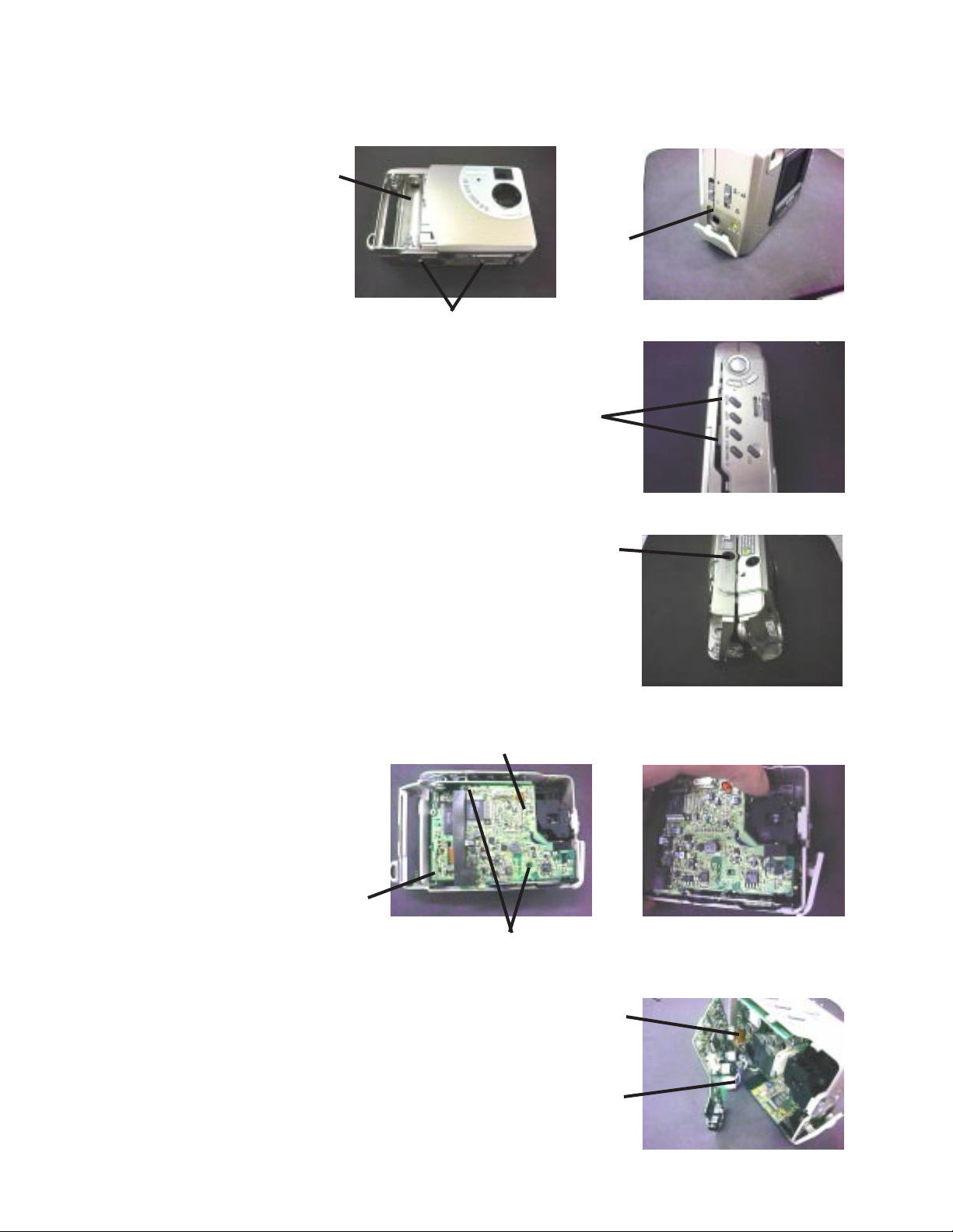
1. Remove the four screws.
Screw
2. Unhook the upper side of the unit, then open
the case from the upper side.
DISASSEMBLY
Screw
Screws
Hooks
3. Be sure not to lose the bright knob, then remove the case.
4. Remove the two screws on the linear
PCB, then disconnect between the linear
and digital PCBs.
Digital PCB
Linear PCB
Bright knob
Screws
5. Disconnect the wire for the back light and the flat
cable for the LCD, then remove the linear PCB.
Flat cable
Wire
— 6 —
Page 9

6. Remove the key PCB and two screws on the digital PCB.
Key PCB
Screws
Digital PCB
7. Remove the two screws on the camera unit.
8. Unhook the slide switches of the camera unit, then remove
the digital PCB and the camera unit.
Screws
Camera unit
Switch
9. Remove the three screws, then remove the back light.
Note: Be sure not to lose the spacer.
Screws
Back light
Spacer for LED
— 7 —
Page 10

ASSEMBLY
The assembly can be done by reverse order of the disassembly steps. The notes of the assembly are as follows;
1. Be sure to set the spacer and sheets on the LCD as the figure.
LCD
Dimmer sheet
Diffuser sheet
2. Be sure to align the switches on the camera unit with the switch knobs.
3. Be sure to align the slide switch on the key PCB with the switch knob for power.
LCD spacer
Switches
Switch knobs
Switch knob
— 8 —
Slide switch
Page 11

LINEAR
PRINTED CIRCUIT BOARDS
C113
R113
R111
R110
C145
R115
1
C120
C125
C111
L103
IC100
1
R114
C110
C404
IC400
C405
C123
R150
C127
C152
1
D106
C144
IC150
R411
C402
R120
C151
L105
C154
Q150
C311
R306
R305
C129
R310
R309
R334
R337
L300
D105
Q101
C140
C338
C313
R144
R308
C304
R121
C142
R141
R142
H300
C318
R307
R303
FU101
R335
R302
C143
C336
C305
C306
R141
IC101
1
C322
C301
R301
C319
C304R340
L100
C320
C346
C300
R338
C324
R327
LED2
R333
R321
R332
C329
C333
R323
C330
C331
R325
R324R322 R328
C332
R320
C307
R345
C355
VR302
R319
C335
R316
R317
R321
Q301
C350
C351
C352
C343
R344
1
IC301
C356
R350 R349
C353
L302
L301
JK300
C354
R123
R122
R124
Q104
Q102
VR303
C323
R318
R337 C325
CN100
Top View
R129
1
R331
R330
R300
R326
VR300
C100
VR101
CN150
C326
C327
R313
VR301
1
C317
R336R312
IC300
C303
C302
C309
C308
T150
L303
R412
C401
VR400
T100
C112
C415
C418
C121
D102
R428
C410
D101
1
R410
R413
C406
R414
C407
C416
Q100
R429
VR100
C408
R401
C413
C409
R426
R402
C412
R430
1
CN400
R415R409
R314
R315
C339
R407
C315
R311
C316
C314
C310
C312
C101C153
R420
R424
C411
1
R405
R427
L102
D103
D104
C150
R403R408
R406
R404
R421
Q401
Bottom View
— 9 —
VR304
Page 12

DIGITAL (QV-70B)
FU500
L732
C722
C540
1
C505
CN601
Q511
1
R505
C543
IC503
R507
R508
1
C545
T500
C542
L642
Q512Q513
R654
C617
Q503
R514
JK500
L602
R511
R512
R516
C531
IC602
R652
R653
R510
C520
IC507 IC504
C651
L601
L600
L641
C630
EM2
C518
Q508
R521
C516
C650
C619
11
D601
D603
1
C622
C623
L621
L622
R520
C517
C606
R519
IC603
R622
R600
R607
C602
R611
R601
C704
L703
L704
R522
C519
R614
1
C548
R619
R620
L702
R700
C705
R617
R616
C609
R621
C700
C522
R602
C504
C503
R503
L700
1
R651
Q502
FU501
C603
Q510
CA601
IC600
C615
C544
R655
R502
L730
R750
IC700
C546
R504
C508
RA700
R613
D501
RA704
Top View
L502
Q500
L503
C507
IC500
1
C501
VR500
C506
C703
C717
CN602
C541
1
C710
R715
L701
C702
L505
D502
R501R523
R500
RA701
C709
R650
RA702
R618
1
L501
C708
1
C600
D505
IC502
C511
Q501
D500
R702
C706
R703
1
C719
RA602
L504
L619
C721
L640
C718
RA603
RA601RA600
C613
C512
R506
L620
C663
C612
C525
D503
1
R610
C662
CN600
L729
C701
IC604
L624
R644
L633
R624
L731
R716
C716
C611
C601
C620
L631
H700
L506
RA604
C621
IC601
L632
C661
CA600
IC605
L639
C664
L540
D506
Q612
IC701
1
R615
RA703 RA705
Q611 Q610
C624
R605
1
Q514
R515
L643
R606
R517
C523
C521
JK600
IC506
R518
1
R509
1
SW101
SW100
IC505
1
C524
R513
Bottom View
— 10 —
Page 13

DIGITAL (QV-70C)
FU500
L732
C540
C722
1
C505
CN601
Q511
R505
1
C543
IC503
R507
R508
1
C545
T500
C542
L642
Q512Q513
R654
C617
Q503
R514
JK500
L602
R511
R512
R516
C531
IC602
R652
R653
R510
C520
IC507 IC504
C651
L601
L600
C650
L641
C630
EM2
C518
R521
C516
C619
11
Q508
D601
D603
1
C623
R622
L621
L622
R520
C517
C606
R519
IC603
C622
R600
R522
C519
1
R607
R611
R601
C704
L703
L704
R614
C602
R619
L702
C705
R617
R616
C609
C548
R620
C700
R700
R621
C522
R602
C504
R651
Q502
R503
C503
L700
1
C603
FU501
Q510
CA601
IC600
C615
C544
R655
R502
L730
R750
IC700
C546
R504
C508
RA700
R613
L502
L503
D501
IC500
RA704
C541
1
Top View
Q500
C507
D502
1
C501
VR500
C506
C703
C710
R715
L701
C702
C717
CN602
L505
R501R523
R500
RA701
C709
R650
RA702
R618
1
IC502
1
L501
C708
C706
R703
C600
C511
Q501
D500
R702
C719
RA602
L504
D505
L619
C721
L640
1
C718
C613
C512
R506
L620
C663
RA603
RA601RA600
C612
C525
D503
1
R610
C662
CN600
C701
L733
IC604
L624
R644
L633
R624
L729
L731
R716
H700
C716
C611
L506
IC703 IC702
RA604
C601
C620
C621
IC601
L631
L632
C661
C664
IC701
CA600
IC605
L639
L540
D506
Q612
11
1
R615
RA703 RA705
Q611 Q610
C624
R605
1
Q514
R515
L643
R606
R517
C523
C521
JK600
1
IC506
R518
SW100
R509
IC505
C524
1
R513
SW101
1
Bottom View
— 11 —
Page 14

EXPLODED VIEW
5
11
5
5
46
48
1
2
3
4
6
7
8
9
10
46
12
13
14
15
16
17
18
19
20
21
22
23
24
25
26
27
28
29
30
31
32
33
34
35
36
37
38
39
40
41
42
43
44
45
50
50
47
47
48
49
46
16-1
46
— 12 —
Page 15

PARTS LIST
LINEAR PCB ASS'Y
Item Code No. Parts Name Specification Applicable Q R
Diodes
D101 7101 1194 DIODE MA111-(TX) Common 1 C
D102 2390 1379 DIODE/SCHOTTKY MA729-(TX) Common 1 C
D103 2390 1379 DIODE/SCHOTTKY MA729-(TX) Common 1 C
D104 7101 1194 DIODE MA111-(TX) Common 1 C
D105 2390 1379 DIODE/SCHOTTKY MA729-(TX) Common 1 C
D106 2360 2359 DIODE/ZENER MA8180-L(TX) Common 1 C
Fuse
FU101 3122 3332 FUSE ICP-S0.5TN Common 1 B
ICs
IC100 2114 5800 IC MB3800PFV-G-BND-EF Common 1 C
IC101 2114 5800 IC MB3800PFV-G-BND-EF Common 1 C
IC150 2105 3990 IC TC7S02F-TE85L Common 1 C
IC300 2114 5537 IC/LINEAR IR3P90Y1 QV70B (NTSC) 1 C
IC300 2114 5740 IC/LINEAR IR3Y21 QV70C (PAL) 1 C
IC301 2105 6378 IC MM1228XFBE Common 1 C
IC400 2015 0147 LSI MSM6770CGS-2K-6004 Common 1 C
Jack
JK300 3501 5439 JACK HSJ1456-01-210 Common 1 C
LED
LED2 2370 1393 LED SLR-332VC3F Common 1 C
Transistors
Q100 2253 0308 TRANSISTOR 2SD1119-R(TX) Common 1 B
Q101 2253 0308 TRANSISTOR 2SD1119-R(TX) Common 1 B
Q102 7911 0126 TRANSISTOR/DIGITAL DTC144EUAT106 Common 1 B
Q104 2251 0189 TRANSISTOR 2SB1218A-R(TX) Common 1 B
Q150 2253 0700 TRANSISTOR 2SK1485-T1 Common 1 B
Q301 2251 0189 TRANSISTOR 2SB1218A-R(TX) Common 1 B
Q401 2251 0189 TRANSISTOR 2SB1218A-R(TX) Common 1 B
Converter and Transformer
T100 3065 0693 CONVERTER/DC-DC TTV6DD360M02 Common 1 B
T150 3012 1414 TRANSFORMER/INVERTER BLC10-01 Common 1 B
Variable resistor
VR304 2775 0644 RESISTOR/SEMI-FIXED H0614D-10KB Common 1 C
Notes: Q – Quantity used per unit
R – Rank
— 13 —
Page 16

DIGITAL PCB ASS'Y
Item Code No. Parts Name Specification Applicable Q R
Diodes
D500 2390 2268 DIODE MA727-(TX) Common 1 C
D501 2360 1876 DIODE/ZENER MA8100-M(TX) Common 1 C
D502 2390 1379 DIODE/SCHOTTKY MA729-(TX) Common 1 C
D503 7101 1194 DIODE MA111-(TX) Common 1 C
D505 2390 2261 DIODE MA720-(TX) Common 1 C
D506 2390 1421 DIODE/SCHOTTKY MA738-(TX) Common 1 C
D601 2390 1379 DIODE/SCHOTTKY MA729-(TX) Common 1 C
D603 2390 1379 DIODE/SCHOTTKY MA729-(TX) Common 1 C
Fuses
FU500 3632 0715 FUSE F1206A1R50FW-TP Common 1 A
FU501 3122 3332 FUSE ICP-S0.5TN Common 1 A
ICs
IC500 2114 5800 IC MB3800PFV-G-BND-EF Common 1 C
IC502 2105 3969 IC RH5RH503B-T1 Common 1 C
IC503 2105 3689 IC RN5RG50AA-TR Common 1 C
IC504 2105 3976 IC RN5RL25AA-TR Common 1 C
IC505 2105 1407 IC/CMOS TC7S00F-TE85L Common 1 C
IC506 2105 5215 IC/CMOS TC7W74FU(TE12L) Common 1 C
IC507 7911 2982 IC RN5VL25AA-TR Common 1 C
IC600 2012 5769 LSI HD6437034SK24F QV70B (NTSC) 1 C
IC600 2012 5832 LSI HD6437034AK28F QV70C (PAL) 1 C
IC601 2012 3591 LSI HM514800CLJ Common 1 C
IC602 2012 2793 LSI TC5816AFT-1 Common 1 C
IC603 2105 4305 IC TC7S04F(TE85L) Common 1 C
IC604 2105 6460 IC XC61BN3812MR Common 1 C
IC605 2105 5719 IC TC7W32FU(TE12L) Common 1 C
IC700 2011 9457 LSI HG51B167FB Common 1 C
IC701 2012 3598 LSI HM538123BJ QV70B (NTSC) 1 C
IC701 2012 3605 LSI HM538253BJ QV70C (PAL) 1 C
IC702 2105 3990 IC/CMOS TC7S02F-TE85L QV70C (PAL) 1 C
IC703 2101 1061 IC/CMOS TC7S32F-TE85L QV70C (PAL) 1 C
Jacks
JK500 3501 6755 JACK HEC3600-010120 Common 1 C
JK600 3501 6538 JACK HSJ1169-012010 Common 1 C
Switches
SW100 3412 1106 SWITCH/SLIDE SSSS212-12 Common 1 B
SW101 3412 2076 SWITCH SKHUBB-T Common 1 C
Transistors
Q500 2253 0308 TRANSISTOR 2SD1119-R(TX) Common 1 B
Q501 2253 0308 TRANSISTOR 2SD1119-R(TX) Common 1 B
Q502 2251 0882 TRANSISTOR 2SB1073-(TX) Common 1 B
Q503 2251 0189 TRANSISTOR 2SB1218A-R(TX) Common 1 B
Q508 2253 0133 TRANSISTOR 2SD1819A-R(TX) Common 1 B
Q510 2259 2715 TRANSISTOR/DIGITAL DTC144EETL Common 1 B
Q511 2259 2715 TRANSISTOR/DIGITAL DTC144EETL Common 1 B
Q512 2259 2715 TRANSISTOR/DIGITAL DTC144EETL Common 1 B
Q513 2259 2715 TRANSISTOR/DIGITAL DTC144EETL Common 1 B
Q514 2259 2715 TRANSISTOR/DIGITAL DTC144EETL Common 1 B
Q610 2259 2731 TRANSISTOR/DIGITAL DTA114EE-TL Common 1 B
Q611 2259 2715 TRANSISTOR/DIGITAL DTC144EETL Common 1 B
Q612 2254 0448 FET 2SK1580-T1 Common 1 B
Converter
T500 3701 0693 CONVERTER/DC-DC CEE98-05 Common 1 B
Notes: Q – Quantity used per unit
R – Rank
— 14 —
Page 17

KEY PCB ASS'Y
Item Code No. Parts Name Specification Applicable Q R
Switches
SW900 3412 1421 SWITCH/SLIDE ESD165227 Common 1 B
SW901 3412 1995 SWITCH SKQRAA-T Common 1 C
SW902 3412 1995 SWITCH SKQRAA-T Common 1 C
SW903 3412 1995 SWITCH SKQRAA-T Common 1 C
SW904 3412 1995 SWITCH SKQRAA-T Common 1 C
SW905 3412 1995 SWITCH SKQRAA-T Common 1 C
SW906 3412 1995 SWITCH SKQRAA-T Common 1 C
SW907 3412 1995 SWITCH SKQRAA-T Common 1 C
SW908 3412 1995 SWITCH SKQRAA-T Common 1 C
Notes: Q – Quantity used per unit
R – Rank
— 15 —
Page 18

MAIN COMPONENT
Item Code No. Parts Name Specification Applicable Q R
1 6612 4210 PANEL/LOWER R340140-1 Common 1 X
2 6612 4280 TAPE/ADHESIVE R440277-1 Common 1 X
3 6612 4100 COVER/PROTECTOR R240098-1 Common 1 X
4 6612 4160 PROTECTOR/LENS R440232-1 Common 1 X
5 6612 4270 TAPE/ADHESIVE R440264-1 Common 7 X
6 6612 4040 PROTECTOR/FINDER R440220-1 Common 1 X
7 1014 9715 FINDER LF-010S Common 1 X
8 6612 4030 PROTECTOR/LED R440221-1 Common 1 X
9 6612 3970 CASE/LOWER R140025-1 Common 1 X
10 6603 8924 KNOB K3741D-1 Common 1 X
11 6020 7658 SPRING/BATTERY P408A-1 Common 2 X
12 6612 4010 COVER/BATTERY R240101-1 Common 1 X
13 6612 4310 BLINDER R440273-1 Common 1 X
14 6605 8240 CUSHION K410316-4 Common 1 X
15 1014 9714 CAMERA UNIT LS-009E Common 1 B
16 6612 5579 PCB ASSY/KEY R340193*1 Common 1 C
16-1 6612 4540 CABLE/JOINT R440272-1 Common 1 C
17 6612 5578 PCB ASSY/LINEAR R240146*1 QV70B (NTSC) 1 B
17 6612 6379 PCB ASSY/LINEAR K240772*1 QV70C (PAL) 1 B
18 6612 5650 CUSHION R440279-1 Common 1 X
19 6612 5577 PCB ASSY/DIGITAL R240145*1 QV70B (NTSC) 1 B
19 6612 6378 PCB ASSY/DIGITAL K240771*1 QV70C (PAL) 1 B
20 6612 4180 SPACER R440230-1 Common 1 X
21 6612 4190 SPACER R440231-1 Common 1 X
22 6612 4220 SPRING/BATTERY R440224-1 Common 1 X
23 6612 4230 SPRING/BATTERY R440225-1 Common 1 X
24 6612 3980 BUTTON R240099-1 Common 1 X
25 6612 3990 BUTTON R340132-1 Common 1 X
26 6612 4000 BUTTON R340131-1 Common 1 X
27 6612 4070 BUTTON R340139-1 Common 1 X
28 6612 4020 SPACER R440222-1 Common 1 X
29 6612 4060 KNOB/POWER R340137-1 Common 1 X
30 6612 4080 KNOB/APERTURE R340135-1 Common 1 X
31 6612 4090 KNOB/FOCUS R340136-1 Common 1 X
32 6612 4110 COVER/CONNECTOR R340138-1 Common 1 X
33 6612 4050 KNOB/REC R340133-1 Common 1 X
34 6611 4390 HOLE/TRIPOD R340024-1 Common 1 X
34 6612 4290 LABEL/BATTERY R440270-1 Common 1 X
34 6612 5640 LABEL/CAUTION R440262-2 QV70B (NTSC) 1 X
35 6612 8030 LABEL/CAUTION R440262-3 QV70C (PAL) 1 X
36 6612 8040 LABEL/CAUTION R440262-4 QV70C (PAL) 1 X
37 6612 5680 LABEL/RATING R440239-2 Common 1 X
38 6612 4120 HOLDER/DISPLAY R240100-1 Common 1 X
39 6612 3960 CASE/UPPER R140024-1 Common 1 X
40 2725 1338 DISPLAY ASSY COD18T1014LN Common 1 B
41 6612 4130 SPACER/LCD R440227-1 Common 1 X
42 6612 4140 SHEET/DIMMER R440228-1 Common 1 X
43 6612 4150 SHEET/DIFFUSER R440229-1 Common 1 X
44 6612 5580 BL ASSY R340190*1 Common 1 B
45 6612 4200 SPACER R440226-1 Common 1 X
46 5860 0301 SCREW BT3 1.7X3.5 NI Common 7 C
47 5861 3551 SCREW M 1.7X3.0 Bk Common 2 C
48 5861 3549 SCREW PT3 1.7X3.5NI Common 3 C
49 5860 0091 SCREW BT3 1.7X4.5 Bk Common 2 C
50 5861 3527 SCREW BT3 1.7X2.5 Bk Common 3 C
Notes: Q – Quantity used per unit
R – Rank
— 16 —
Page 19

ACCESSORY
Item Code No. Parts Name Specification Applicable Q R
51 3851 2078 STRAP ST-K770 Common 1 X
52 1014 8773 CABLE/VIDEO VC-K723-FC Common 1 X
53 1014 9783 CASE/SOFT SC-770 Common 1 X
Notes: Q – Quantity used per unit
R – Rank
— 17 —
Page 20

LINEAR (QV-70B)
SCHEMATIC DIAGRAMS
— 19 —
Page 21

LINEAR (QV-70C)
Video Out
9
86
Display Controller
5
Chroma IC
10
7
To LCD
To Digital PCB
Power Supply for LCD
2
1
4
To Back Light
3
Power Supply for Back Light
— 20 —
Page 22

DIGITAL (QV-70B)
To Linear PCBTo Key PCBDC in
DRAM
CPU
24
Flash
Memory
Data Expander
Data Compressor
Video Encoder
Digital I/OTo Camera Unit
13
VRAM
5 V
5 V
5 V
141211
18 V
To Camera Unit
–9.5 V
— 21 —
Page 23

DIGITAL (QV-70C)
To Linear PCBTo Key PCBDC in
DRAM
CPU
AK28F
Flash
Memory
Data Expander
Data Compressor
Video Encoder
Digital I/OTo Camera Unit
13
VRAM
5 V
5 V
5 V
141211
18 V
To Camera Unit
–9.5 V
— 22 —
Page 24

KEY
— 23 —
Page 25

WAVEFORMS
QV-70B QV-70C
6.4 µsec
1 IC100 pin 5
6 µsec
4 Q101 collector
0.8 V
2 Q100 collector
6.8 V
5 IC300 pin 10
4.4 V
10.1 V
6 µsec 6.4 µsec
3 IC101 pin 5
1.0 V
63.5 µsec 63.5 µsec
6 IC300 pin 21
4.4 V
0.7 V
4.8 V
6.4 µsec
1 IC100 pin 5
6 µsec 64 µsec 64 µsec
4 Q101 collector
0.8 V
2 Q100 collector
6.8 V
5 IC300 pin 10
4.4 V
0.7 V
10.1 V
6 µsec 6.4 µsec
3 IC101 pin 5
1.0 V
4.8 V
6 IC300 pin 47
4.4 V
63.5 µsec
7 IC300 pin 20
125 µsec
0 IC300 pin 30
125 µsec
8 IC300 pin 39
6.0 V
4.8 µsec 4.8 µsec
A IC500 pin 5 (Switch to the
REC position.)
44 V
63.5 µsec
9 IC300 pin 36
0.8 V
B T500 pin 1 (Switch to the
REC position.)
22 V
4.0 V
10 V
64 µsec
7 IC300 pin 20
125 µsec
0 IC300 pin 30
125 µsec
8 IC300 pin 39
6.0 V
4.8 µsec 4.8 µsec
A IC500 pin 5 (Switch to the
REC position.)
44 V
4.0 V
64 µsec
9 IC300 pin 36
0.8 V
10 V
B T500 pin 1 (Switch to the
REC position.)
22 V
4.4 µsec 4.8 µsec
C T500 pin 5 (Switch to the
REC position.)
D T500 pin 8 (Switch to the
REC position.)
— 24 —
4.4 µsec 4.8 µsec
C T500 pin 5 (Switch to the
REC position.)
D T500 pin 8 (Switch to the
REC position.)
Page 26

CASIO TECHNO CO.,LTD.
8-11-10, Nishi-Shinjuku
Shinjuku-ku, Tokyo 160, Japan
Telephone: 03-3347-4926
 Loading...