

Page 1

Repair Guide for QV-10
INDEX
Vol. 1 Basic Repair
Contents
PAGE
Requirement ..................................................................................................
Equipment and Tool ....................................................................................
Disassembly ..................................................................................................
Troubleshooting .............................................................................................
No power on .................................................................................................
Picture element is missing when print out ...................................................
Sudden power failure ...................................................................................
Assembly .......................................................................................................
Major points .................................................................................................
Data Restoring ...............................................................................................
Memory error reset ......................................................................................
Creating backup file .....................................................................................
Restoring images stored in QV-10 memory error ........................................
After Replacing the Digital PCB .....................................................................
Color Adjustment ...........................................................................................
Initializing the Flash Memory ..........................................................................
Vcom Adjustment ...........................................................................................
Appendix .......................................................................................................
Usage ..........................................................................................................
1
1
3
4
4
6
7
8
8
9
9
10
11
12
13
14
15
18
18
Page 2
Requirement
Equipment and Tool
PERSONAL COMPUTER
IBM PC/AT or compatible RS-232C serialport ( D-Sub 9-pin )
MS-WINDOWS Ver 3.1 or later Mouse or other pointing devices
4MB of RAM (8MBrecommended ) 3.5" 1.44MB disk drive (for installation )
10MB available hard disk space
Color monitor ( full-color recommended)
386SX CPU or higher (486SX recommended )
SERVICE UTILITY SOFTWARE
FLASH. EXE
AMED.EXE
ADJ.EXE
LIGHT BOX HANDY 5000
for Color adjustment
COLOR FILTER LBA 3
for Color adjustment
OSCILLOSCOPE
REGULATED DC POWER SUPPLY
PHOTO DIODE
-1-
Page 3
Equipment and Tool
CABLE
PHOTO SENSOR AMP.
ANALOG VOLTMETER
KOTELYZER
SOLDERING IRON and SOLDER
TWEEZERS and SCREW DRIVER
-2-
Page 4
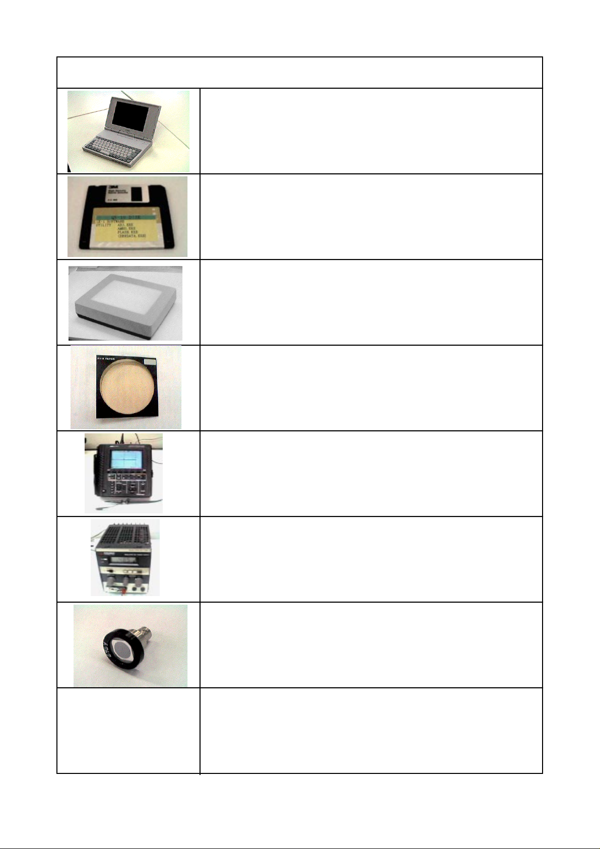
Disassembly
Procedure
Remove the two screws from the lower case.
Remove the two screws from the lower case.
Pull out the lower case.
Take the battery cover.
Pull out the keyborad PCB from the digital PCB.
-3-
Page 5
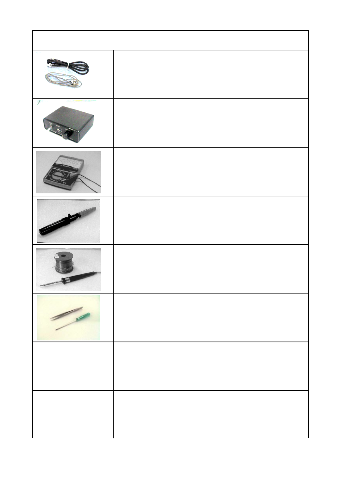
Troubleshooting
Procedure
No power on
Check the power switch.
Check the fuse (FU500) by using multimeter.
Take the fuse (FU-100) by using multimeter.
Replace the backlight or the LCD.
Pull out the flat cable from the digital PCB.
Remove the three screws from the upper case.
-4-
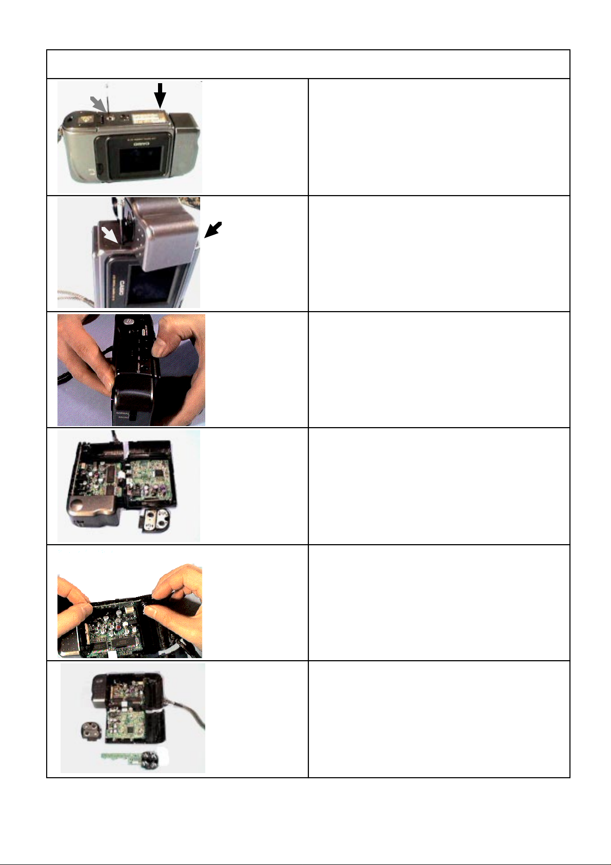
Page 6
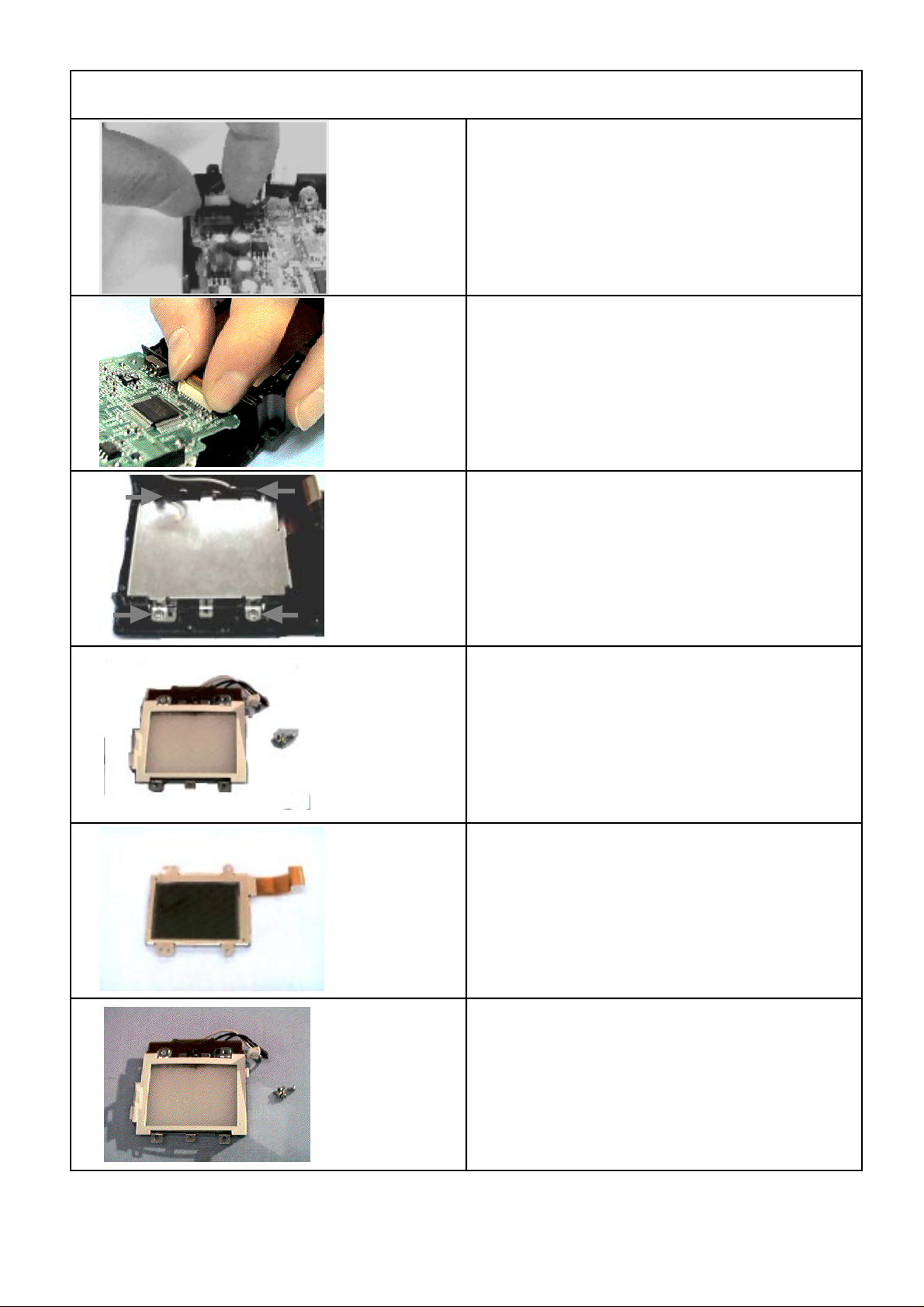
Procedure
Remove the connector from the linear PCB.
Loose the connector then the release hook. Pull out
the linear PCB.
Remove the four screws from the upper case.
Replace the backlight.
Replace the LCD.
Vcom adjustment is necessary when changed the
LCD.
See page 14.
-5-
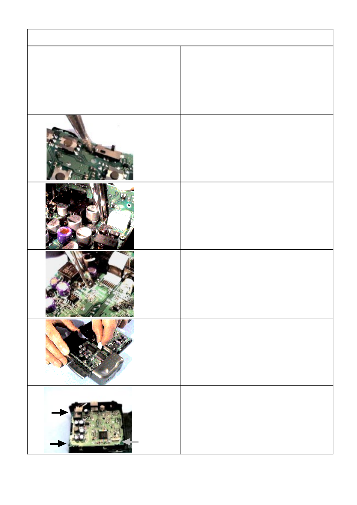
Page 7

Procedure
Picture element is missing when print out.
Defective the camera unit.
Remove the two screws.
Pull out the two connectors.
Pull out the two flat cables from the connectors.
Replace the camera unit.
Color adjustment is necessary when changed it.
See page 13.
-6-
Page 8

Procedure
Sudden power failure.
Poor soldering on the power jack.
Remove the one screw from the lower case.
The coonector(s) of the power jack should be
soldered.
-7-
Page 9

Assembly
Procedure
Major points
Assembly can be performed in the reverse order of
the disassembly steps.
There are three majorpoints of assembly work.
1. Set the point of the slide switch to the switch knob.
2. Gently set the switch knob to thepoint of the slide
switch.
3. Push hard the upper case with both hands in the
direction of the lower case.
-8-
Page 10

Data Restoring
Procedure
Memory Error Reset
C:\>
Memory error message appears on the display, when
QV-10 finds onerror in the internal flash memory.
Install the QV-10 service utility on your computer.
Create a directory for the QV-10 service utility on drive
C.
C:\>md qv10
Directory already exists
C:\>copy a:\*.exe
A:\ADJ.EXE
A:\AMED.EXE
A:\FLASH.EXE
3 file(s) copied
C:\>
M Space Q V 1 0D EnterPress
to create the root directory
Press
to copy the QV-10 service utility on to the suitable
directory.
C SpaceP Y A :O \
E X E Enter
.
*
-9-
Page 11

Procedure
Remove the QV-10 service utility disk from drive A.
Connecting QV-10 (DIGITAL terminal) to your
computer (D-Sub 9-pin).
RS-232C port
(D-Sub 9-pin)
Creating backup file.
C:\>cd qv10
Directory already exists
C:\qv10>flash - s BACKUP
Use the cable and adaptor that come with LK-1 kit
when connecting to your compurer.
Turn on your computer and camera.
Press
to change from the current directory to the directory
where the utility FLASH.EXE exists.
Press
C Space Q V 1 0D Enter
F SpaceA S H -L S
B A C Enter
K U P
*filename
Space
Saving flash memoryto "BACKUP" 100%
to create back file .
* "The length of filename is up to eight characters."
1. To quitthe utility. Press Escape.
2. In case of "Time out Error";
* Select the suitable com port or change slower bit
rate,then retry.
* Make sure that all connections between the QV-10
and your computer are secure.
-10-
Page 12

Procedure
Restoring images strored in QV-10 at memory error.
C:\>cd qv10
C:\qv10>amed -PIR
QV-10 Automatic Memory Error Debugger V er 1 . 0
Serching management block....
Found a t bank 1FF Status----OK
Saving system block a s "mngblk.dat"
Saving system block a t bank 1FE a s "sysblk.dat"
Image No. 1 i n 006....00A save a s "Image001.CAM"
Image No. 2 i n .................save as "Image002.CAM"
........................
---Initiallize Flash Memory
---Create management block
---Reset
If need a change of directory,
Press
Press
C Space Q V 1 0D Enter
A SpaceE D - PM I R
Enter
to load the images on to hard disk and restores the
images on the computer.
Restore system block a t bank 1FE from"syblk.dat"
Loading image "Image oo1.cam"
Loading image "Image oo2.cam"
....................
C:\qv10>
-11-
After restoring, the utility clears all original images in
the camera and copies the restored images into the
camera.
In case of "Time out Error", select the suitable com
port or change slower bit rate, then retry.
Page 13

After Replacing the Digital PCB
Procedure
C:\>cd qv10
C:\qv10>flash -l BACKUP
Loading finish memory from "Backup 100%"
If need a change of directory,
Press
Press
to copy the original images on the hard disk into the
camera.
The message on the camera's monitor will change
"MEMORY EMPTY" to "MEMORY ERROR".
C Space Q V 1 0D Enter
F SpaceA S H
L L
B A C Enter
K U P
-
Space
C:\qv10>amed -PIR
QV-10 Automatic Memory Error Debugger V er 1 . 0
Serching management block....
Found a t bank 1FF Status----OK
Saving system block a s "mngblk.dat"
Saving system block a t bank 1FE a s "sysblk.dat"
Image No. 1 i n 006....00A save a s "Image001.CAM"
Image No. 2 i n .................save as "Image002.CAM"
........................
---Initiallize Flash Memory
---Create management block
---Reset
Restore system block a t bank 1FE from"syblk.dat"
Loading image "Image 001.cam"
Loading image "Image 002.cam"
....................
C:\qv10>
Press
to load the images on to hard disk and restores the
images on the computer.
A SpaceE - PM I R
Enter
D
-12-
Page 14

Color Adjustment
Procedure
Color adjustment should bedone;
1. after replacing the digital PCB ass'y.
2. after replacing the camera unit.
3. after using the utility FLASH.EXEfor copying the
images taken by another camera.
4. after using the utility FLASH.EXE for initializing the
flash memory.
Put on the color filter on the screen of the light source.
Set the aperture switch to F8 ( ) psotion and turn on
the camera.
C:\>cd qv10
C:\qv10>adj
Connect the QV-10 to your computer with LK-1, and
put the camera with its lens toward the light source.
Turn on your computer and the light source.
Press
to change the directory where the utility ADJ.EXE
exists.
Press
The message WAIT appears on the monitor of the
camera.
C Space Q V 1 0D Enter
A D J Enter
-13-
Page 15

Procedure
System block 1FE
CYSUM 3254E GRSUM 1EC33
RKY A 6 RKC D RKG FEDD
BKY 0 BKC FB BKG FEDD
GKY 0 GKC FFD9 GKG 12 3
ALPHAFFFC BETA A8 TINT 9 8
RAlimit - L 3 2 6 RAlimit-H 5 5 3
BAlimit-L 44 0 BAlimit-H 7 F0
MOA-CY 1CB MOA-GR 266
COL-KAT 0 COL-BAS 3E Y-OFFSET 5
RAMP-INIT 40 0 BAMO-INIT 5A 0
C:\qv10>
Initializing the Flash Memory
C:\qv10>amed - i
QV-10 Automatic Memory Error Debugger ve r 1 . 0
- - - Initialize Flash Memory
--- Create management block
--- Rest
C:\qv10>
Press
A SpaceE D -M I Enter
A screen becomes monochrome when initializes hte
flash memory, and color adjustment is necessary.
See page 13.
-14-
Page 16

Vcom Adjustment
Procedure
Vcom adjustment
Oscilloscope
A fine adjustment of Vcom adjustment
VR302
GND
6.0 +/- 0.1V
TP-410
It is required whenever replacing the TFT-LCD.
Outputpoint: TP-410
Adjust: VR-302 and VR303
Probe
VR303
1. Ajust VR303 so that square-wave to read
6.0 +/- 0.1V.
2. Adjust VR302 so that high level of the square-wave
is at 0 +/- 0.25V.
Select TEST mode to check a fine adjustment of Vcm
adjustment.
While pressing the MODE and Shutter button, slide to
the right to turn on power.
Press the self-timer and DEL button at a time.
Press (+) or (-) button to select the BLACK.
-15-
Page 17

Procedure
Press the shutter button.
Connect a cable to a photo diode and a photo sensor
(IN).
Connect a cable to an oscilloscope and the photo
sensor (OUT).
Place the photo diode on the middle of the display.
-16-
Page 18

Procedure
Turn on the photo sensor Amp. and set RF RANGE in
LOW.
Adjust VR302 for ripple at minimum.
-17-
Page 19

Appendix
Usage
AMED
AMED : QV-10 Automatic Memory Error Debugger version 1.0 07/21/95
Usage: AMED (-spir) (-com1 | -com2 | -com3 | -com4)) (-b9600 | -b19200 | -b38400| -b57600)
- s : Save system block
- p : Save system block a nd image data
- i : Initialize Flash Memory. I f image data a r e saved, restore them.
- r : Restore system block
-com* : Selectco mport channel(default = com1)
-b**** : Select b i t rate (default =57600 BPS)
FLASH
Usage: FLASH (-s|-l) <filename> (-com*) (-b9600 | -b19200 | -b38400| -b57600)
- s : Save flashmemory to thefile
- l : Loadt h e file to flash memory
-com* : Selectco mport channel(default = com1)
-b**** : Select b i t rate (default =57600 BPS)
-18-
Page 20

CASIO COMPUTER CO., LTD.
OVERSEAS SERVICE DIVISION
8-11-10, Nishi-Shinjuku
Shinjuku-ku, Tokyo 160, Japan
Telephone: 03-3347-4926
FAX: 03-3347-4973
Printer in Japan
 Loading...