

Page 1
CAS
I D.
Handheld
Termina
l
IT
-G5QQ
Series
User's Gui
de
Be sure
to
read "Safety
Precauti
ons"
Inside this
guide before trying to use
your Handheld Terminal.
'
/
=
ur
-
CAS
IO
(illl{E)_BaEJ@)
0
(0
@;1~0
@;)
19
1!9
1!11!:.1
fZ3~~1CLA
I
::::::
Ei)IQ:]
0
;··:··
• 0 .
=
\
E
Page 2

0
Bluetooth
'
• BLUETOOTJlls a registered tr adem
ark
owned
by
Bluet.ooth
STG,
Tnc.
and
licensed
to
CASIO
COMPU
TER
CO.,
LTD.
• M icrosofl
and
Windows
arc either registered
tr-ddemarks
or trademarks
.of
M icrosofl
COI}lOmtionln
the United Stutes and/or other countries.
• "FcliCu"
is
a contactless
IC
card technology developed
by
SONY
Corporation and a
registered
tmdemark
of
SONY
Corporation.
Tnformatlon
in
this
document
is
subject
to
change without
advan
ce
notice.
CAS
IO
Com
puter Co.,
Ltd.
makes
no
representations
or
warranti
es
with
respect
to
the
content~
or use
of
this
manual
nnd
spc
ci1lcally
disclaims
ony
expr
es~
or
implie
d wan·
auties
.ofmerchuntuhility
or
fitness
for
any
particular
purpose.
Page 3
Contents
Safety
Precautions
......................................................................................... E-3
Operating
Precautions ...................................................................................
E-8
Regulatory
lnformation
..................................................................................
E-9
About
the
WaterprOOflng/Dustproofing,,.,,._..,,nuouuouono.-ooooooo••••••••••••--•••••·E-13
ltnport.
ant
...
....................................................................... _ .
.......
...........................
E-14
After Service ...................................................................................................... E-14
Accessories
and
Options
............................................................................... E-15
General GUide
u.u.oooo.ouo.ooo.ooooooooooooooooooooouooooooooooooooouuou
.
ouooo·o,u•·oo·o·
ooo'noooo
ooo
ooooooooooooE•16
Loading
and
Removing the
Battery
Pack
................................................... E-19
Loading
.......
....................................................................................................... E-20
Removing
.........................................................................................................
..
E-20
Charging
the
Battery
Pack
.......................................................................... E-22
USB
Cradic/Ethernet
Cmdlc/Cnu.l
lc-typc
Bat1c
1y Charger ............................... ll-22
Dual
Battery
Charger
......................................................................................... E-22
Handling
the
Hand Belt ................................................................................ E-23
To
remove
the
hand beh ..................................................................................... E-23
To attach
the
hand
belt .......................................................................................
E-23
Handling
the
Stylus ......................................................................................
E-24
Placing
the stylus in
the
hol
der
..........................................................................
E-24
Connecting
tt1e
Stylus Strlng ...............................
....
...................................... E-
25
Attaching
the
Neck
Strap ........................................ ..................................... E-27
To
attach
the
neck
stntp ..........................................................................
.....
....... E-27
Configuring
Handheld Terminal Settings ...................................................
E-28
Calibrating
Touch
Screen
AI i
gnment ................................................................. E-28
Adjusting Display Hrighln
css
............................................................................ l
:'.-2
9
D
isplay Amo Dimmer ........................................................................................ E-29
Using
the
Laser
Scanner (Laser Models) ................................................... E-30
U
sing
the
C-MOS Imager
(Imager Models) ................................................ E-31
Adjusting
the
Laser
Light
Emission
Width
................................................. E-32
HandJJng
the NFC ............ -............................................................................. E
..
34
E-1
Page 4
Perfom
ling
Communicat
ions
.......
.........................
......
..............
......
............ E-35
Bl
uetoolli"
Communication .........................................................
...................... E-35
GSM/W-CDMA
Communicati
on
...........................
.......................................
.... I'.-36
GPS
......
...
.............................................................
...
...........................................
E-36
Handling microSD
Ca
rds .............................................................................. e
..
37
Ins
talli
ng
..............................................................................................................
R-37
Removing ..
...........................................................................
...
...............
.........
..... E-37
Handling rnicroSIM Cards ............................................................................ E
..
38
In~tal
ling
.....
................................
...........................
.....
.....................
...
.............
...
. E-38
Rcmovi ng ........................................................................................................
... E-39
Using the microSD Hard Cover {IT·G500-GC21E only) ...................
........... E-40
Attaching the microSD
Hnrd
Cover
to
the I landheld Terminal... ......................
F\-40
Resetting the Handheld Terminai ................................................................ E-41
Performing a Full Reset (Iuitiali
7.ation)
.........................................................
...
I:l-4
I
War
nin
g Label .......................
...
..................................................................... E
..
43
IT·G500 Specifications ................................................................................ E
·44
Using the USB Cradle (HA·P6010), Ethernet Cradle (HA·P621
0),
Cradle-type Battery Charger (HA-P30CHG) ............................................... E-53
General Guide ...................
...
............................
...
............................................... E!-
53
Connecting tbe Cradle Power Supply ...................................
....
......................... E-55
Ethernet Cradle Specifications (IIA
-l'62TO)
...
................................................... E-57
USO
Cradle Specifications (HA-P6010) ..
......
.................................................... E-
SR
Cradle-type Battery Charger Specifications (HA-P30C
II<i
) ............................. E-59
Using the Dual Battery Charger (HA-D32DCH
G)
.............................
....
...... E-60
General Ouidc ................................................
.....
...............................................
E-60
Charging a Battery
Pack
.................
.............
..................
.....
.......
.......................... E-62
Connecting
Multiple
Dual
Ilattety Chargers
...
................................................... E-63
Specifications ...
...
......................................... _ ............................
...
.......................
E.-64
Us
i1l
9 the micro U
SB
.. .-..
....
..........
. u
........ _ ............ _ ..........
......
...................
...
...
...............
"'
• • E
..
G-5
Connecting
to a Comp
uter ................................................................
...
.............. E-65
Usi
ng Rec
har
geable
Battery
Packs .
........................................................... E-66
Battety Pack Specifications ............................
...
................................................. E-66
Large-capacity llattery
Pack Specifications ....................................................... E-66
Using the Protector (HA·P91BP5, HA-P92BP5) ......................................... E
-67
Fitting the protector onto
the
llandheld Tenninal.. .......................................
.....
E-67
Removing the protector fr
om
the Handheld
Terminal
.......................................
P..-67
E-2
Page 5
Safety Pr
eca
utions
Congratulations upon your selection
of
this
CAS
IO
product.l.le sme to tead the
following
Safety Preca
ution
s hclorc trying
to
use it tor the
first
time.
Y
our
neglect
or
avoidance
of the warning and caution statements
in
the
subsequent pages causes the danger
of
fire, electric shock, malfunction and
damage
on
the goods
as
well as personal injury.
Mar
kings and Symbols
The following arc the meanings
of
the
markings and symbols used
in
these Safety
Precautions.
~D
ang
e
r
This symbol indicates information that,
if
ignored or applied
in
correctly, cre
ate
s the danger
of
death or serious personal injury.
Lt.
W
arnin
g
This symbol
indicutes information that,
if
ignored or appl
ied
incon·ectly, creates the possibility
of
death or serious personal
injury.
~C
aution
This symbol illdicates information that,
if
ignored
or
applied
incotrcctly,
creates the possibility
of
personal injury or property
damage.
• A diagonal line indicates
~omethillg
you should not
do.
The symbol shown
here
indicates you should not try
to
take the
uni
t apart.
•
A black circle indicates someth
ing
you should do. The symbol shown he
re
indicates
you
should unplug
the
unit
from
the
wall
outl
et.
~
Wa
l'niu
g
Disassembly and Modification
J<ii'\
• Never try
to
disassemble
or
modify
the
Handheld Terminal and
its
options
\JY
including battery pack and battery
in
any
way.
Abnorm
al
Conditions
0
•
Should
the
Handheld
Terminal
und/or
its
options including battery pack and
baucry
become hot
or
start
to
emit
smoke
or a strange
odor,
immediately
turu
off
the
power
and
contuct your
dealer or distributor
whom
you
purchased
the
product from, or
1111
authorized CASlO setvice
provider.
E-3
Page 6
E-4
& Warning
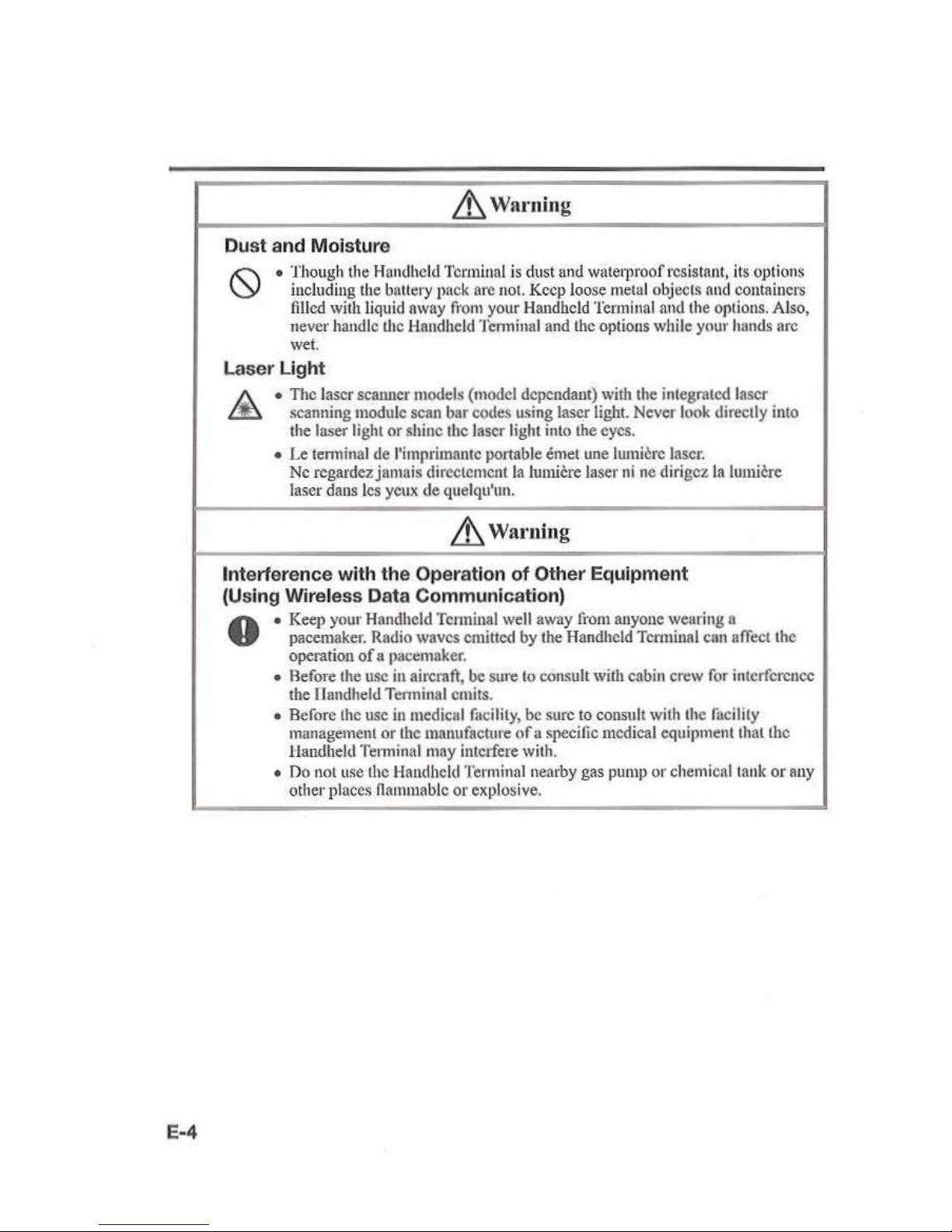
Dust and Moisture
• Though the Handheld Terminal is dust
und
waterproof resistant, its opti
ons
including
the
battery pack
are
not.
Keep
loose
metal
objects
and
containers
filled
with liquid
away
from
your Handheld
Terminal
and
the
options. Also,
never handle
U1c
Handheld Tenninal and the options while your
hands
arc
wet.
Laser Light
•
The
laser scanner models (model dependant)
with
the integrated laser
scanning module
scan
bar codes using laser
light.
Never
look
directly into
the
laser light
or
shine the laser light into the eyes.
• Le
tem1inal
de l'imprimautc ponable emet une lumicrc
laser.
Nc
rcgardez jnmais dircctcmcnt
Ia
lumiere laser
ni
nc
di•·igez
Ia
lumicre
laser dans
lcs
yeux
de quelqu'un.
& Warning
Interference with
the
Operation
of
Other Equipment
(Using
Wireless
Data
Communication)
A • Keep your Handheld
Terminal
well
away
fi·om
anyone wearing a
V pacemaker. Radio waves emitted by the Handheld Terminal can
ufTect
the
operation
of
a pacemaker.
•
Aefore
the
usc
in
aircrnft, be sure
to
consult with cabin crew
for
interference
the
llandheld Tenninal emits.
• Before
the
usc
in
medical
facility,
be sure to consult with the lacility
munagement
or
the manufacture
of
a specific medical equipment that the
tlandheld Tenninalmay
intc1fere
with.
•
no
not use the Handheld Tenninalnearby gas p
ump
or chemical tank
or
any
other places nanuuablc
or explosive.
Page 7
Lt.
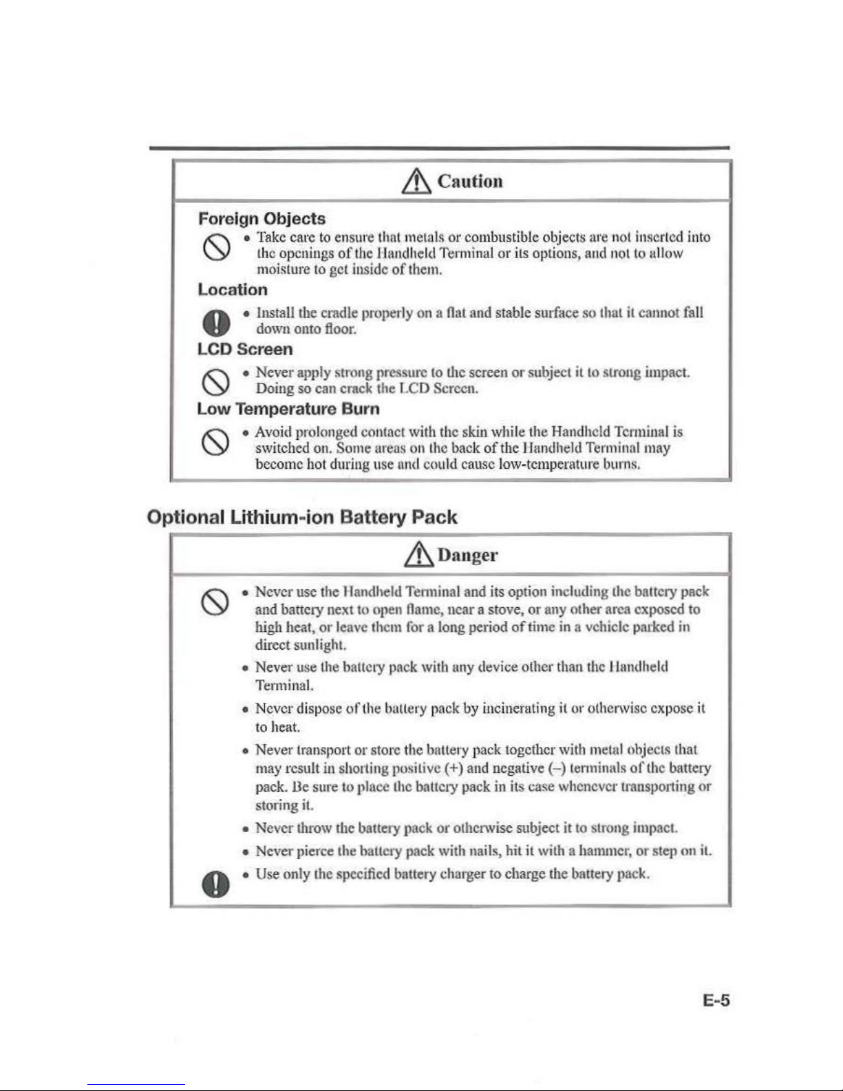
Cauti
on
Foreign Objects
!(:\
•
Take
care
to
ensure that metals or combustible objects
are
not
insert
ed
into
\Y
the
openings
of
the llandheld
Terminal
or its options, and not to
ullow
moisture to gel
inside of
them.
Location
A • Install the cradle properly
on a Oat
and
stable surface so that
it
cannot
fall
V
down
onto
floor.
LCD Screen
!(:\
• Never apply strong
pressw-c
to
the screen or subject
it
to
strong impact.
\Y
Doing
so
can crack
the
LCD
Screen.
Low
Temperature Burn
•
Avoid
prolonged contact with the skin while the Handheld Tcnniual is
switched
on.
Some
ureas
on
the
back
of
the Handheld
Terminal
may
become
hot
during use
nnd
could cause low-temperature
bun1s.
___
_.
Opt
ional Lithium-i
on
Battery
Pack
Lt_na
nger
0
• Never usc the Handheld Tenninal
and
its option including the battery pack
and battery next
to
open
name,
ncar a stove, or any other
area exp
osed
to
high
heat, or leave
them
for
a long period
of
time
in
a vehicle parked
in
direct sunlight
•
Never
use
the
battcty
pack
with
uny
device other
than
the
llandheld
Terminal.
• Never dispose oflhe battery pack
by
incinerating
it
or otherwise expose
it
to
heat.
• Never transport or store the bnttery pack together
with
metal
ohjects thai
may
result
in
shorting positive(+)
and
uegalive
(-)
lenninals
oft
he battery
pack.
lle sure to
pln
cc
the battery pack
in its case whenever
transp
o11ing
or
storing
it.
• Never throw the battery
pack
or otherwise subject it
to
strong
impact.
• Never pierce the hallcry pack
with
nails, hit it with a
hammer,
or
step on
it.
• Use only
the
specified battery charger
to
charge the battery p
ack.
E-5
Page 8
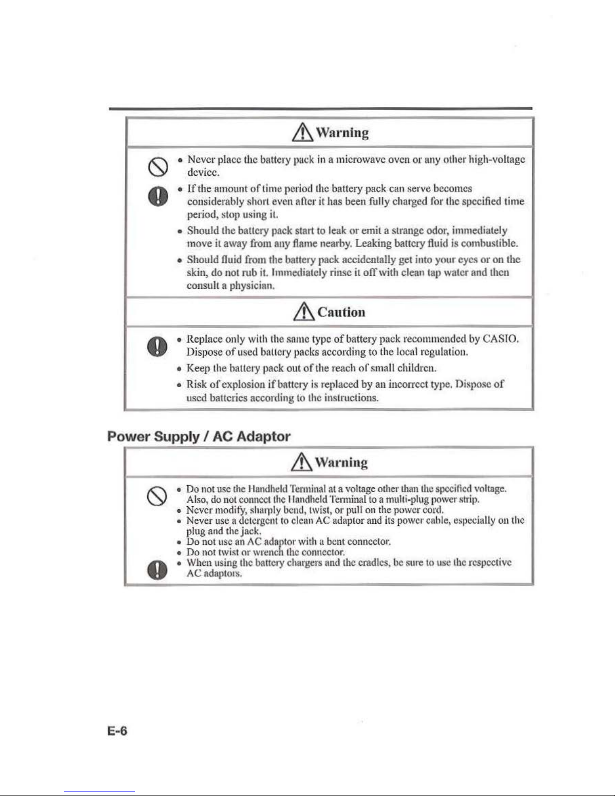
~Warning
0
• Never place the battery
puck
in
a microwave oven or
any
other high-voltage
device.
0
•
lfthe
amount
of
tim
e period
the
battery
pack
can serve becomes
considerably
sh
ort
even aficr it
has
been
fully charged
for
the specified time
period, slop using
it.
• Should the battery
pack
start to l
eak
or emil a strange odor, immediately
move it away
from
any
fl11rne
nearby. Leaking battery
fiuid
is
combustible.
• Should lluid
from
the
b11ttery
pack accidentally
get
into your eyes or on the
skin,
do
not
rub
it.
Immediately rinse
it
off
with clean tap water
and
then
consult
a physician.
.&,
Ca
ution
0
• Replace only
with
the same
type
of
bnttery pack recommended
by
CASTO.
Dispose
of
used
b<lllery
packs accordir1g
to the local regulati
on.
• Keep the battery
pack
out
of
the reach
of
small children.
• Risk
of
explosion
if
battery
is
replaced
by
an incorrect type. Dispose
of
used
batteries according
to
the
instructions.
Power
Supply I AC Adaptor
E-6
.&,
Waming
•
Do
not
use
the
llondheld
Terminal
at a voltage
other
than
the
specified
voltage.
Also,
do
not
connect
the
llandheld
Temunal
to a multi-plug
power
shiJ>.
• Never
modi
f)',
shat·ply
bend,
twist,
or
pull
on the
power
cord.
•
Never
use
a
detergent
to
cleu
n
AC
udaptor
and
its
power
cuhle,
tlspcciully
ou
the
plug
and the jack.
•
Do
not
usc
an/\C
adn/>tor
with a
bent
connector.
•
Do
not
twist
or
wrcne 1 the
connector.
• When
using
the
battety chargers
and
U1c
cradles,
be
sure
to
usc
the
rcspcct'ivc
AC
adaptors.
Page 9
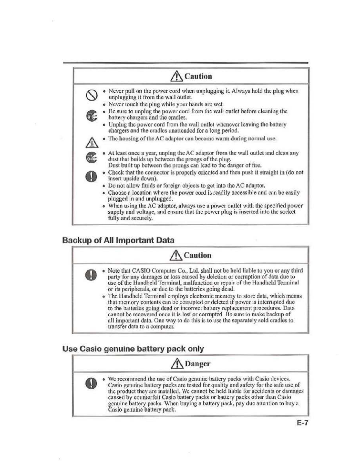
Lh
Cau
tion
• Never pull
on
the
power
cord
when
unplugging
it.
Always
hold
the
plug
when
unplugging
it
from
the
wall
outlet ·
•
Never
touch
the
plug while your
hands
arc wet
•
De
Slll'C
to
unplug
the
power
cord
fromlhc
wall
outlet before cleaning
the
battery chargers
and
the
cradles.
•
Unplug
the
power cord
from
the wall outlet whenever leaving the hnttery
chargers
and
the cradles ltnattcodcd for a long period.
• The housing
of
the
AC adaptor can become warut during
normal
use.
•
All
cast once a year, unplug the
AC
adaptor
from
the
wall
outlet
and
clean
any
dust
that builds
up
between the
pi'Ongs
of
the
plug.
Dust built
up
between
the
prongs
can
lead
to
the danger
of
fire.
• Check that the connector
is
properly oriented
and
then
push
it
straight
in
(do
not
insert upside
down).
•
Do
not allow
fluids
or
foreign
objecL~
to
get
into
the
AC
adaptor.
• Choose a locati
on
where
the
power
coni is readi
ly accessible
nnd
can
be easily
plugged
in and
unplugged.
• Wh
en
using the
AC
adaptor,
always use n
powe
r outlet
with
the
S(>Ccified
power
supply
and
voltage,
and
ensure that the power plug
is
inse11ed
into
the
socket
fully
and
securely .
Backup of All Important Data
&,ca
ution
8
•
Nore
that
CASIO
COIIl(lUter
Co
.,
Ltd. shall not he
held
liable
to
you
or
any
tbird
party
for
any
dama11cs
or
loss
caused hy deletion or
cOITUption
of
clata
due
to
use
ofU1e
l:landheld
Terminal, malfunction or
•·epair
of
the
Hrmdhcld
Terminal
or
its
peripherals, or due
to
the
batteri
es
going d
ead.
• The
Handheld
Terminal
employs
elecb·onic
memory
to
store data,
which
means
that
memory contents
cun
be
com1
ptcd
or deleted
if
power
is
intCI1'llptcd
due
to
the batteries going
dead
or incorrect battery replacement p•·ocedures. Data
cannot
be recovered once it
is
lost or corrupted.
l:le
sure
to
make
backup
of
all
important data. One
way
to
do
this
is
to
usc the separately •old
crudlcs
to
transfer data
to a computer.
Use Casio genuine battery pack only
&,Danger
8
•
We
recommend the
use
ofCasio genuine battery packs
with
Casio
devices
.
Casio
genuine battery packs are
tested
for
quality
and
safety
for
the safe
usc
of
the
product
they
ure
installed.
We
cannot
be
held liable
for
accidents or damages
cmt~ed
by
counterfeit
Cnsio
battery packs or battery packs other
than
Casio
genuine batte•y
packs.
When
buying a hattery pack,
pay
due
attention
to
huy
a
Casio
genuine battery
pack.
E-7
Page 10
Operating Precautions
E-8
Your
Handheld Terminal
and
its opti
ons are precision. Improper operation or
rough
handling can cause problems
with
data storage
and
other problem
s.
Note
and
observe
the follow
it
ig
precautions
to
ensure proper opcmtion.
•
Do not cont inue using the bntlery once
it
is
exhausted.
D
oi
ng
so could result in data l
oss
or
comtption.
When the battety is exhausted,
replace
it immediately.
• Stop
or
avoid using fhc Handheld Terminal and its options in
ru·cas
nnd
conditions subject to
the foll
owing.
-Large
amounts
of
static electricity
-
Exb·
eme heat
or
co
ld
or humidity
- Sudden temperatnre change
-Large
amount
of
du
st
- After
large
amount
of
rain
or
water
falls
ou
the Handhe
ld
Terminal
- Pressing the screen or keys with excessive force when using
in
the rain
•
Do not u
se volatil
e chcmlcul substan
ces
such as thinnc•
·s, hcn:tcnc or
toiletries to
clean the H
and
held Termhutl.
Wh
en
the Han
dhe
ld Tcrmin
nl
is di
rty, wip
e it clean with a soft, dry cloth. Rubb
ing
with excessive force could scmtch the display.
•
The
J
>Ower-S
UJlll
ly t
e1·mi
nals nnd Data Communication terminals should
be
cleaned f•·om lime to time u
si
ng nu implement such as a
dr
y cotton bud.
Soilit1g
on
the
tem1inals
may cause cotmcction
defectS.
• Take cnt'e when nsiug chc
mi
culs.
Applying thinners, gasoline,
kerostJne,
~o
lvents
or
oils, or substances such
as
cleaners,
adhesives, paints, medicati
ons
or toiletri
es
that contain those materiuls,
to the plastic
case or cover may
cause
discoloration
or
other damage.
• D('ad Pi xels
The
LCD
panel employed
in
thi
s produ
ct
uses high precision and substantial number
of
components which commonly cause a small number
of
the pixels not
to
light or
to remain lit all the time. This is
due
to
the characteristics
of
LCD panel yield
in
aecura.
cy
over 99.99% and permissible.
• 802.1laln Restrictions
- This product
is
for
indoor
lL~e
only when using channels 36, 40, 44,
48
, 52, 56,
60,
or 64
(5
150-5350
Mll7.)
.
-T
o ensure complian
ce
with
local regulations,
be
sure
to
select the country
in which
the
access point
is
installed.
Page 11

• Lltblum-lon Batt
ery
PAck
Each
lithium-ion
battery
pack
has
Its
life. TI1e
Lifo
spanlleavlly
depends
ou
how
tbe
ballery
pack
is
cluugcd
or
stored
which
may
et1use
detedornlion
of
the
ball
cry
pack
to
shorten
the
life
span
if
it
is
handl
ed
improperly. Note
the
tips
below
to
make
the
battery pnck
lnst
long.
- Be sure
to
charge the battery paok before using it
if
the baltcry pack
is
used
for
tho
fu-st
time or
if
it
hns
not been used for a long period
of
time. When
ehnt-giug
tl1e
battery pack, continue charging until the charge
LED
ligl1t8
green (fully
chOI"ged).
- I f the battery pack
is
repeatedly charged, t
he
life span becomes short. To uvoid the
repetition
of
charging
tho
battery
puck,
be sure
1t~at
the remaining capacity is low
before you start charging.
- Be sure to
charge the battery pack
in
recommended temperature range. The
temperatme range
is
dependant on device you use
to
charge including battery
chargers and tablets. Refer
to
tho respective user guides. Charging the battery pack
in a temperature outside
of
the recommended range causes deterioration.
- When
\tsed
111
low
tempemtures,
tho
b111tcry
pack
has a
reduced
Cllpnclty
and
will
supply power for shorter time. The life
spnn
of
the battel}' pack
is
nlso
shortened.
- Charging the battery pack while the battery pack itself
is
freeze
Including inside
causes deterioration.
Be
sure
to resume
an
ordinary
room
temperature
011
tho
battery
,pack and then
leave
it
unattended for opproximntely one hour before
cllnrglng.
- After charging the battery pack,
if
lite performance oftbc battery
pn
ck does
not
sbow
any
recovery,
it
is
a sign
ol
ending the life.
Replace
it
with n new battery pack.
-
Avoid
the
battery pack
with n full_oftbe
capacity to store f?r.a long
pe:io~
of
lime.
lf
you need
to
store 11 for !I long penod,
bo
sure
that
tbe
remammg
onpac1ty
IS 30
to
50
percent
n11d
to
store
in n modem
to low
temperal\1re.
This
cnn
reduce deterioration.
- The battery
pack grndunlly deteriorates over ti
me.
In
particular, storing (or
using}
the fully charged battery pack at high temperatures tends
to
tlccelerate battery pack
deterioration.
• Weld Lines
There are seam-like markings
in
some locations
on
the Handheld Temlinal.
111esc
nrc
referred
to
as
"weld
lin
es"
in
the plastic forming process
n11d
are
not
crocks
or
scratches.
Weld
lin
e.~
do
not
interfere
in
any way witb tbc operation oftbe
Hnndheld
Tem1innl.
Regulatory Information
Europe
IT-G500
Manufacturer:
CASIO COMPUTBR C
O.
,
LTD
.
Op
tloos
ofi
T-GSOO
6-2, Hon-mnchi 1-chome, Shibuya-ku,
Tok.yo
151-8543
, Jupan
(€
Responsible within the European Union:
Caslo
Europe GmbH
Casio-Platz l, 22848 Norderstedt, Gennany
www.caslo-eurcpo.com
•
Pl
ease keep
nU
lnfonnation for futuro reference.
• The declaration
of
conformity may be consulted
at
http://doc.casio.com
• Products are for distribution within all member states
of the
EU.
•
Options
ofiT-0500
are
RA-P60IO,
IIA-P6210,
HA-P30CHO,
HA-D32DCHG,
EIA-D20BAT-A,
HA-021
LBAT-A,
DT-380USB-A, AD-
S42120C.N5,
AD-S I 5050B-N5,rutd
AC-CORD-EU.
For Europe, models are IT-0500-C 168, n:.osOO-OC26E,
IT-
0500-I
SE,
IT-0500
-2SE,
l'f-GSOO
-C26E,
IT-GSOO-GC 16E, IT-OS00-0 l5B,
IT-GSOO-OC21 E,
n:.
osoO-GC21
1!rS1:
IT
-G500-GC26E-T
R,
IT-GSOO-OC16J!...TR,
JT-0500-0ISE-T
R, IT-GSOO
-C21E,
IT-0500-CI6E-B, IT-0500-0C26
B-
B,
IT-0500-C26E-B, 1T-G5
00-0C16E-
B,
n :.osoO-GlSI!rB, 1T-0500-
0C21.E-
B,
l'f-0500-GC2LE-ST-B, n :.osoO-OC26E-TR-B,
IT
-0500-0CJ 6E-TR-
B,
and
1T-0500-C21
E-B.
E-9
Page 12

Maximum radio output power
• IEEE802.lla/b/g/n: 2.40Hz band:;; 20dBm; 5GHz
band
~
14dBm.
•
Oluetooth:
2.40
Hz ~ 5.80dBm.
• GSM: 850/900MHz ~
JJdllm;
1800/1900MHz s JOdBru.
• WCDMA:
900/2JOOMHz
~24dBrn.
•
NFC:
13.553MHz
to
13.567MHz
band:;; -8.5dB!tAfm at I Om.
Hereby, CASIO COMPUTER CO.,
J~m
.
declares that tbe radio equipment type IT-0500 is
in compliance
witb Directive 20 14/53/EU.
E-10
Page 13
The USA and Canada
GU
IDELINES LA
lO
DOWN
BY
FCC
RULES FOR U
SE
OF
THIS UNIT
IN Til
E
U.S.A. (not applicable to oth
er
lli'CliS).
NOTI
CE
This cquipmentJJas been tested and
found
to
comply with the limits for a Class B digital
device, pursuant
to
Part
15
of
the FCC Rules. These limits are designed to
t>rovide
rea~onable
protection against hannful interference
in a 1·esidential
installation. This
equipment generates, uses and can radiate radio frequency energy and,
if
not
in~talled
and used
in
accordance with the instructions, may cause hannful interference
to
rndio
communications. However, there
is
no
guarantee that interference will
not
occur
in
a
particular installation.
lf
this equipment docs cause hlnmful interference
to
radio or
television reception, which can
be
detcnnined by tuming
U1c
equipment
off
and on,
the
user
is
encouraged
to
try to correct
the
interference hy one or more
of
the following measures:
•
Reorient
or
relocate the receiving antenna.
• increase
the separation between
the
equipment and receiver.
• Connect the equipment into
an
outlet
on
a circuit
diJTorent
from
that to which
the
receiver
is
connected.
• Consult
the
dealer or
an
expel'ienccd radiofrV technician for help.
FCC
WARNING
Chauges or modifications
not
expressly approved
by
the party responsible for compliance
could void the
tL~er's
authority
to
operate the equipment
Proper connectors must
be
used
for
connection to host computer and/or peripherals
in
order
to
mecl FCC emission limits.
Cn
ution
Elt
posure to nullo ft·equency rndlatio
n
To
comply
with
FCC
/IC Rl7 exposure compliance requirements, this device must not be
co-located or operating in conjunction
with
any other antenna or trunsmitt
cr
except
in
accordance with the FCC multi-transmitter product
procedure.<;
or
as
described
iuthe
filing.
Model
Number:
Trade
Name:
J)
cclanlllou
of
Confonnily
I'J'
-G500-C21
F.-l/S,
IT-G500-C21E-US-R. HA-PI\010
, HA-
P6210
CASTO
Responsible
pa1ty:
Industrial Handheld Division
Casio America,
Tnc
.
Addt
·ess: 570 Mt. Pleasant Avenue, Dover, New Jersey
07RO
I,
USA
Telephone number: 973-361-5400
This device
com
plies
wit
h
P:u11
5
of
the
FCC
Rules.
Operation
is
subject to the following
two conditions:
(1) This device
muy
nol cnusc harmful
int
erference,
und
(2)
this device must
nccept
any interference received, Including interference tliat
may
cnuse undesired operation.
E-
11
Page 14

• LT-
GSOO·C21E-US
This
model
is
available
in
the
USA
and
Canada onl
y.
For Usc.-s
in
Canada
These
Class
U digital apparatuses
comply
with Canadi
an
TCES-3(8)/NMB-J
(B).
Cct
nppareil
numerique de
Ia
classes
.0
es
t coufom
1ea
Ia
nonne TCES-3(8)/NMtl-J(R)
du
Canada.
This device
complies with
Tndustry
Canada's licence-exempt
RSSs.
Operation is subject to the following two conditions:
(I)
These devices may not cause interference,
and
(2) These devices must accept
any
interference, including interference that
may
cause
undesired operation
of
this
device.
Lc
present appareil est conforme
aux
CNR
d'ludustrie
Canada
applicahl
cs
nux
appareils
radio exempts
de
licence.
L'exploitution est
autorisee
aux
deux
conditions suivantes :
(I)
l'appareilne doil pas produirc
de
brouillage;
(2)
l'ttlilisatew· de l'apparcil
cloit
accepter tout brouillagc radioelectrique subi,memc
si
lc
bt·oui
Llagc
est susceptible d 'en
(;umpromctlrc
lc
fonctionnement.
• Users should also be advised that 5,150-5,350 MHz band
is
restricted to indoor operation
only.
High-power radars arc allocated
us
primary users
(i.e.
priority
users)
of
the hands
5,250-5,350
MUz
and 5,650-5,850 MHz
and
that these radars could cause interference
and/or damage
to
LE-LAN devices.
•
Lcs
utilisateurs devraienl aussi ctrc a vises que
La
bande
5,150-5,350 MHz est restreinte a une
uti
lisation a l'interieur
seufement.
De
plus, les utilisateurs de
radars
de
haute
puis~auce
sout dcsig
nes
utilisuteurs principaux (c.-
a-d.,qu'ils onl
la
priorite) pour l
es
bnndcs
5,250-5,350
MHz
et 5,650-5,850 Mllz et que
ccs
rada
rs pourraient causer
du
brouitlagc
ct/o1
1 des
dommages
aux
clispositifs
LAN-EL.
Under
Indu
stry
Canada regu
lati
ons,
this
radio transmi
tter
may
only operate using
an
antenna
of
a type and
maximmn
(or lesser) gain approved
for
the transmitter
by
lnd11Stry
Canada.
To
reduce
potential
radio interrcrcnce to other users, the antenna type
and
its
gain
should
be
so chosen that the equivalcut isotropically radiated power (c.i.r.p.)
is
not more
than
that
necessary ror
successful communication.
Conronncmcnt a
Ia
reglementation d'lndustric Canada, le present emcttcur radio pcut
fonctiouncr avec une untenne d'un type ct
d'un
gain
maximal
(on infcricur) approuve
pour
l'emetteur par
Tndustri
c Canada.
Dans
le
but
de
rcduirc les risques
de
brouillagc
rudioelectrique
a l'ilttcntion des
1111tres
ulilisuteurs,
il
faut
choisir le type d'antcnnc ct
son
gain de sortc que
Ia
pui
ssunce
isoh·o,
~c
rayonncc equivalente (p.i.r.e.)
nc
dcpassc
pas
l'
intensitc ucccssaire a l'etablissemcut d'
unc
communication satisfaisantc.
E-12
Page 15

Tito
ovoilable scientific evidence d
oes
not
show that
any
health problems
ore
nssoeioted
with
using low power wireless
devi
ces.
TI1ere
Is
uo
proof, h
owever,
that these
low
JIOWer
wireless devices are absolutely
snfo.
Low
power Wireless devices emit low
leve
ls
of
mdio
ftcqucucy
energy (RF) in the
mict·owove
rnngo
whllc being
used.
Wherens
high
levels
of
RF
cn
n prod
uce
health effects (by
heating
tissue), exposure of low-l
eve
l RP
lhnt
does not
Jl
rOduce
heating effects
en
uses
no
known
adverse health effects. M
nuy
stud
ies
of
low-level
RP
exposures
have
not
found
any
biological
effects
. Some
studies
have
suggested
thnt5omc
biological offecls mighl occur,
but
such findings hnvc not been continued by ndditlonal
research.
I
T-GSOO
-C2
LB-US
has been test
ed
und
found
to
comply wi
th
FCCIIC
mdiulion
exposure
limits set forth
for
an
uncontrolled cnviromuculand meets
lbeFCC
rndio
frcquctl
cy (RI')
13.xposure
Guidelines
and RSS-
1 02 oft he IC
mdio
frequency
(R
F)
Exposure rules.
Lcs eonnaissances scicntifiques
don!
nons disposons n'ont mis
en
evidence
llucun
prolll~me
de sonlt associt a !'usage des npparcils
sons
Jllll
faihle
puissance. Nous
nc
sommcs
cepcndont pas
en
mesure de prouver
quo
ccs
npparcits sans fil il
f.1ible pui
ssance sont
entiereruent
SWlS
danger.
Lcs
npJiarciJS
MOO
S
flJ
a
foible
puissance
ClllCI!CnlllliO
tlnerg
ie
fl'~quence
rndioelectrique (RF) trcs
foible dnns
le
spectre des micro-ondcs lorsqu'lls sont
ulillscs. A tors qu'unc dose cl
cvco
do
RF
pcu
l uvoir
des
cffcts sur
Ia
sonle
(en
chuuJ'runt
les
tissus), !'exposition u de
foib
les R
JI
qui
no
produiscnt
pus
de chalem· n
•n
pns
do
mnuvals
ot
'fcts
conn
us
sur
Ia
sante.
De
nombrcuR
es
6tudcs
ont
et6
mcnees sur lcs expositions
nux
RP foibles et n'out
do!couvert
nuoun
offcl
biologlcJue.
Certaines etudes
on!
sugg6r6
qu'll
pouvuil y a voir certains effets biologiques,
nuli
s ces
r(!sul!ats
n'onl pns
cto
confinu~
par des
recherches supplcmenta.
irc.
q.
11~
GSOO-C2LB-US
a etc teste etjug
l!
eonfo
nne
nux
limitcs d'cKposition
nux
rnyonnements
t!nonOO!:s
pour
un
environncmcnlnon eonlrlll
t!
el respecte los regles les
rndiOI!Iectriquos
(RF)
de
Ia
FCC !ignes directrices d'exposition
ct
d'CXJIOSition
au
x
~uences
mdiOI!lcetriqu
es (RF)
CNR-1
02
de
l'IC.
• l'l'·G500-C2JR-US-n
is
the
same
product function
as
IT-G500-C21
E-US.
IT-G500-C2Jt-US-B
is
in
confnrms
with
FCC,
and
not
received
TC
ceni(icntio
u.
About the Waterprooflng/Dustproofing
The n:
osoo
Series
models
ore
wat
erproof
nnd
dustproof.
•
Wat
erproofing: Performnnco
complies
with
the IPX7
level
set
out
in tho
me
slondards
(waterp
roof
for
30
minutes
nt
a depth
of
I
meter
in
still
t
ap
wat
er nt nonnnllempcmture).
• Ouslproofing: Performan
ce
complies with the
IP6X
level
set out
in tho
ffiC
standar d
s.
LP
(lntemalionol Protection) is
tho
alandard for
splash-
nod dus t-
proo
fing
fur
eleclrieol
produciS
set
out in
th
e lntcmolional
ll
lcc:trotechnical Commission (IEC)
o1Rndftrd
60$29.
E-
13
Page 16
Importa
nt!
The
watCI'-
and dust-11r
ooHng
performance of
tl
lis
llroduct is
based
on
CAS
IO
testi
ng
11r
occdures. Note also
that th
is pcrformnu
ce nJl
plie
s to the pmtlu
ct nt the
time
of
shipme
nt (delive
ry
to
the cu
ston1cr)
nud
Is
not guaranteed Inclusive
of
the
environ
ment
In which the
product
is use
d. The
wal'l'nuty
does
not apply
to
nny sltnntlon where
the
product
is
hmuerscd during u
se,
and
as
with
any oth
er
electrical
product,g•·cat care
shou
ld
be
taken when using
thi
s product
in
the rain
01
' similar situation.
•
Pr
ecautions When Using this Produ
ct
-Check
that there is
no
dust,
sand
or
other
foreign
matter
on
the battery
pack
cover,
microSD card slot cover
t)r
microUSB
port/earphone-microphone jack cover, or
on the respective contact surfaces.
If
any soiling is
found,
wipe
it
off
with
a clean,
son, dry cloth.
Even
very
small amounts
of
soiling trapped on
the
contact surfaces
(a
single hair or
grain of
san
d,
etc.)
can
cause water
to
leak into the device.
- Check that the waterproof seals
on
the buttery
pack cover and
microSD
card
slot
cover
are
free li·o
m cracks
nnd
other
damage.
- Cl
ose
the
battery
pack
cove
r l
ock switch finnly
until
the
switch
is
in
the l
ocked position
.
-Avoid
open
ing
and
closing the
buttery
pack
cov
er
or
microSD
card
slot
cover in
locatio
ns
near
wafer
or
exposed
to
sea
breezes,
and
do
not
open or
close them
with
wet
hands.
-Do
not drop
this
product or leave
it
in
locations exposed
to
temperatures outside
the specified
range.
n oing
so
could impair
its
water- or dust-proofing.
• Othc•· Precautions
-The
accessories
for
this product (battery pack, etc.)
and
optional products are
not
water -
or
dust-proof.
-Subjecting
this
produc
t 10 a
severe
impact
could
render
it
no longer
water-
or
dust-proof.
- If any water leaks
into the
product as a result
of
carelessness or inattention during
product handling,
CAS
IO
cannot be
held
liable
for
comp
ensation
for
any
damage
to
internal components (battery, recording
media
, etc.) or for the costs
of reco
rded
co
ntent or
the
recording the1·cot:
-
CASIO
COMP
UTER CO.,
I :
m.
accepts
no
other l
inbilit
y whatsoever
for
any
accident that occurs due
to
water
leakage.
Important
•
This
guide
does
not
include
any
infonnation
about
programming
und
download
procedure.~
.
Sec
the
applkable
separate
documentation
for
infonuation
about the
procedures.
After Service
E-14
•
Should
this product
ever
mul
runcti
on, contact
your
original
retailer
providing
information
about
the
product name, the
dote
you
pwdmscd it,
and
detai
ls
about
the prob
lem.
Page 17
Accessories and Options
Handheld
Terminal
I
T·G500
Series
. -
~
lllfi'
O"GIO
(!i)cm6l
aao
OIDI!i!IEIIZI
lid Q I!AllllEI
nnn~~~~
.
'
Accessories----
---------
-
------...
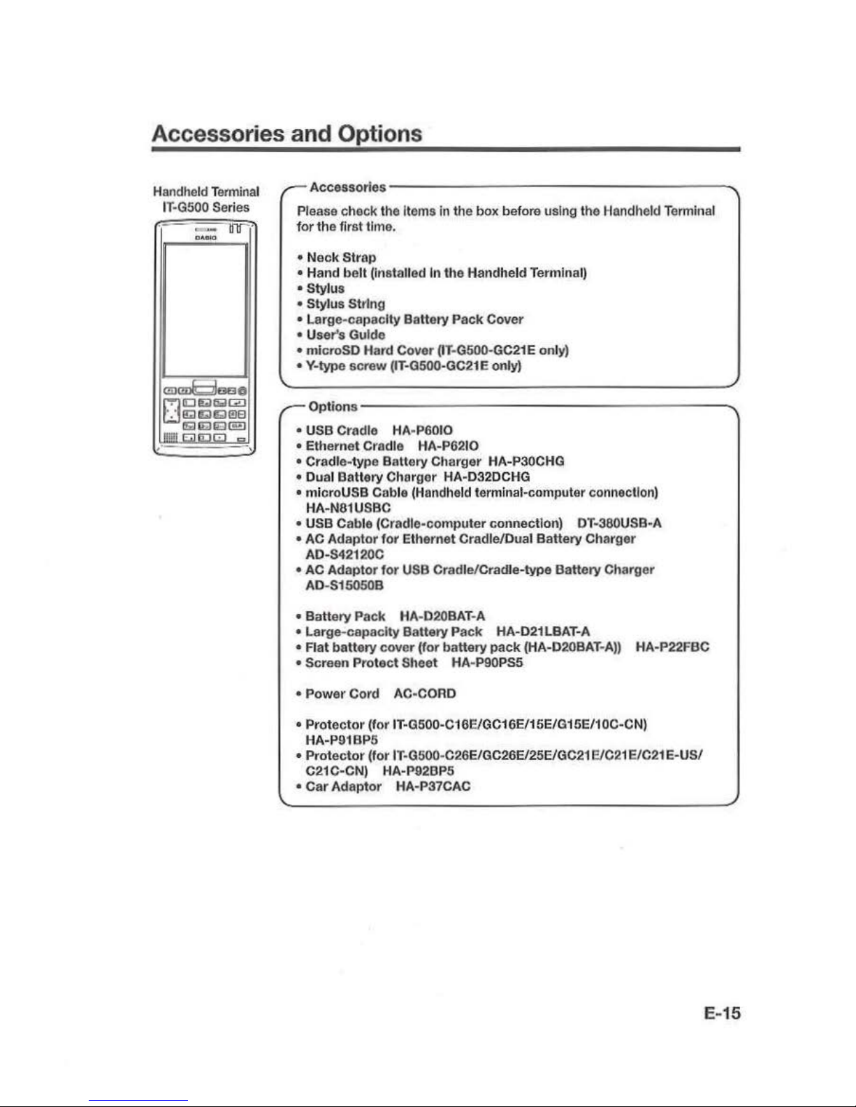
Please check
the
Items in
the
box before using the Handheld Terminal
for
the
first time .
• N
eck
Strop
•
Hand
belt
(Installed In the Handheld Terminal)
• Stylus
• Stylus String
• Large-capac
ity
Battery Pack Cover
• User's Guido
• microSD Hard Cover (IT·G500·GC21E only)
• Y-type screw (IT·0500·GC21 E only)
Options-
----
----
----
--
---
---._
• USB Cradle HA·P6010
•
Ethernet Cradle HA-P6210
• Cradle-type
Battery Charger HA-P30CHG
• Dual Battery Charger HA-D32DCHG
• mi
croUSB
Coble (Handheld t.ermlnal-computer connection)
HA-N81USBC
• USB Cable
(Cradle-computer connection) OT-380USB·A
• AC
Adaptor
for
Ethernet Cradle/Dual Battery Charger
AD-S42120C
• AC
Adaptor
for
USB Cradle/Cradle-type Battery Charger
AD-S15050B
•
Battery Pack HA-020BAT·A
•
Large-capacity Battery Pack HA-021 LBAT-A
• Flat battery cover
(for
battery
pack
(HA-D20BAT-
A))
HA-P22FBC
• Screen Prot
ect
Sheet HA-P90PS5
• P
ower
Cord AC-CORD
• Pr
otector
(for
IT-0500-C16E/GC16E/1
5E/G15E/10C-CN)
HA-P91BP5
• Protector
(for IT-G500-C26E/GC26EI25E/GC21 EIC21 E/C21 E-US/
C21C-CN) HA-P92BP5
•
Car
Adaptor
HA-P37CAC
E-15
Page 18
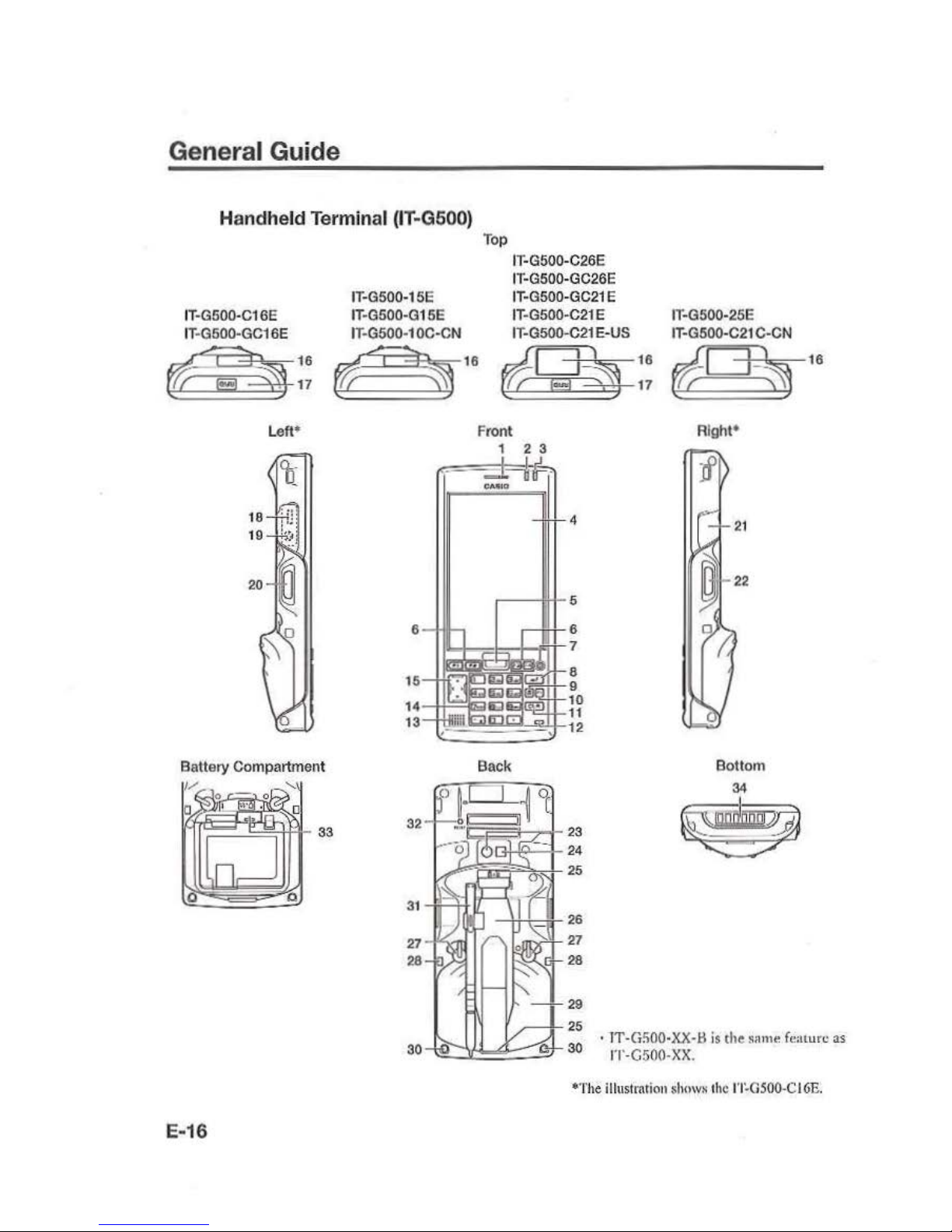
General Guide
Handheld Terminal (IT-G500)
IT·G500·C16E
IT·G500·GCi
6E
IT·G5
00-15E
IT
-G500-G15E
IT
-G500·1
OC·CN
Top
IT-G500-C26E
IT·G500-GC26E
I
T·G
500-GC21 E
IT-G500-C21 E
IT-G500-C21
E·US
t~t1A
tl
~~
¢5?1
~
16
¢~$]
Left•
Battery Compart
ment
Front
1 2 3
4
.---
I'H-
5
.--l+l-6
r~~o..~'""""""±-l-
....f:tr7
15
8
9
14 10
13
-t1~~~
-
~1~-
~)'"="
1'~
Back
16
17
IT-G500-25E
IT·G500-C21
C-CN
(iD
~
Right*
Bottom
34
~
~
16
*T
he
ill
ust
mtion shnws the
1'1~0500-CI6E.
E-16
Page 19
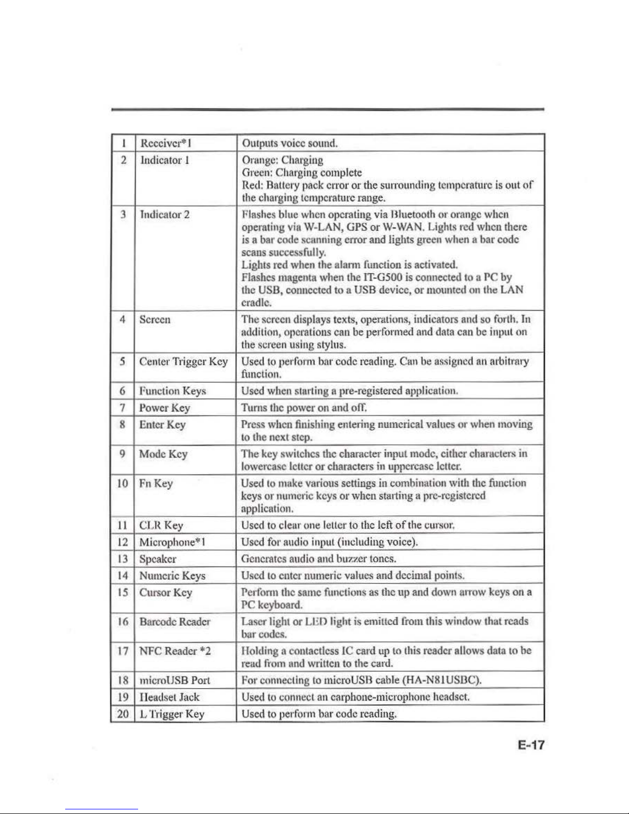
I
Receiver* I
Outputs voice
sound.
2
.Indicator
I
Orungc
: Charging
Gr
een:
Charging complete
Red:
Battery pack error
or
the
sutTOunding
temperature
is
out
of
the
charging temperature range.
3
Indicator 2
Flashes blue
when
operating via Hluetooth or orange
when
operating
via W-LAN,
GPS
or
W-WAN.
Lights
red
when there
is
a bar code scunning
en·or
and
lights green
when
a bar code
scans
successfully.
Lights red
when
the alann
function
is activated.
Flashes magenta
when
the
IT-G500
is connected
to a PC
by
the
USB,
connected to a
USB
device, or
mounted
on
the
LAN
cradle.
4 Screen
Th
e screen displays texts, operations, indicators and
~o
forth.
In
ndditlon
, operations can
be
performed
and
data
can
be
input
on
the
screen using stylus.
5 Center Trigger
Key
Used
to
perform
bnr
code reading. Cnn
be
nssigncd
an
Arbiti'!II'Y
function.
6
Function
Keys
Used
when
starting a pre-registered application.
7
Power
Key
Tums
the
power
on
and
oiT.
8
Enter Key
Pr
ess
when
finishing entering numerical values
or
when
moving
to
the next
step.
9
Mode
Key
The
key
switches the chamcter
input mode,
either chamcters
in
lowercase leiter
or
characters
in
uppercase
lcllcr.
10 FnKey
Used
to
make
various settings
in
combination with the
timclion
keys or numeric
keys
or
when
starting a pre-registered
application.
11
CLR
Key
Used
to
clear one letter to t
he
left
of
the
cur~
or
,
12
Microph
one*
1
Used fo1· audio input (including voice).
13
Speaker Generates audio
and
buzzer tones.
14
Numeric Keys
Used
to
enter numeric values
and
decimal points.
15
Cursor Key Perform the
same
functions
as
the up
and
down
urrow
keys
on
a
PC
keyboard.
16
Barcode Reader Laser light or
LED
light is emilled
from
this
window
lhal reads
bur
codes.
17
NFC
Reader
*2
Holding a eontactless IC card
up
to
this
reader allows data
to
be
read
fi·om
and
written
to
the card.
18
micro
USB
Port
For connecting
to
micro
USB
cab
le
(HA-N81 US.OC).
19
Headset
.Tack
Used
to
connect
an
earphone-m icrop
hone
headset.
20
L Trigger K
ey
Used
to
perform bar code rea
ding.
E-17
Page 20
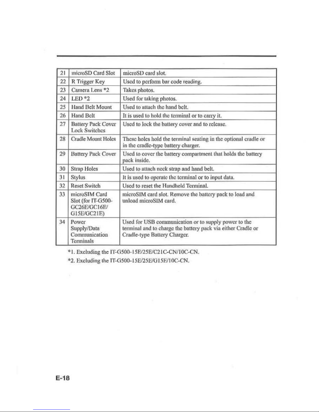
21
22
23
24
25
26
27
28
29
30
31
32
33
34
microSD
Card Slot
microSD
card
slot.
R Trigger
Key
Used
to
perform
bar code reading.
C
amern Len$
"'2
Tak
e.~
ph
otos.
LED*2
Used
for
taking photos.
Haud
Delt
Mount
Used
to
attach the
hand
belt.
Hand
Belt
It is used
to
hold
the
terminal or to cany
it.
Battery
Pack
Cover
Used
to
lock the battery cover
and
to release.
Lo
ck
Switches
Cmdle
Mount
Holes
These holes
hold
the tenninal seating in the
optionnl
cradle
or
in
the
crad
le-type battery charger.
Uattery
Jlack
Cover
Used
to
cover
the
battery compartment that
holds
the
battery
pack
insid
e.
Strap Holes Used
to
1Htach neck strap
and
hand
belt.
Stylus
It
is u
sed
to
opera
te
the
terminal
or to input
datu.
Reset
Switch
Used
to reset
the
Hundheld Terminal.
mi
croS
TM
Card mieroSlM card sl
ot.
Remove
the battery
pack
to
load
und
Slot (for
lT-G500-
unload
microSIM
card.
GC26E/GC16FJ
G15FJGC21E)
Power Used
for
USB
conununicatiou or to
supply power to the
Supply/
Data
tenninal
and
to
charge
the
battery
pack
via
either Cradle or
Communicati
on
Cntdle-type Battery
Charger.
Terminals
+I.
Excluding
the
IT-G500-15E/25E/C21C-CN/I OC-C
N.
*2
. Excluding
the
TT-G5
00-15J1125Il/0 15Fll
OC-CN.
E-18
Page 21
Loading and Removing the Battery
Pack
Your
Handheld Terminal uses two types
of
battery: a battery pack and a memory
backup battery.
The battery
pack
is
used Lo power no
rmal
operations and
to
store data, while
the
memory backup battety
provid
e~
th
e power required
to
maintain
mem
ory conte
nts
when
the
battery pack pow
er
is unable
to
supply power for some reason.
You
can choose either batlery pack (HA-D20
.13A
T-A) or large-capacity battery pack
(H
A-
D21LBAT-A)
for
operatin~
power.
Th
e backup baltery is installed mside
of the
Handheld Terminal.
This guide uses
the
following terms to r
efer
to the batteries.
Battety
Pack:
Rechargeable
batteryJmck
(HA-D20BAT-A
or IIA-021
LOA1~A)
for
nonnal
operntions nn
data
storage
Backup Battery:
Built-in baucry
for
memory
backup
When
the battery pack power goes
low,
immediately charge
it
or replace
it
with
a
charged battery pack.
You
can use
the
Dual Battery Chmger, the Cradle-type Battery Charger, the
USB
Cradle, or
the
Etlternel Cmdlc
to
charge a battery pack installed
in the terminal.
See
the
relevant sections
in
this guide for
the
respective options about
h(lW
to
usc.
Important!
Always
keep bac
kup
of
all
Important
dat
al
• The battery pack
)Jow
ers normal OJleratlon
and
also
provid
es powe1·
requh·ed
to
maintain memot
·y
contents, whtle
the
baclwp haUet
•y
pro
vides
bncl<Uil
power to
maintain memory conte
nt
s. Because
of
this,
yo
u should not remove the battery
1
1ac
.k
if
the
backu11
battct·y
is d
ead
. Removing the battery pack while the backup
batt
ery is dead
cau
se.~
data
in the memory
to
be cot-ruptcd
or
lost. Note
that
once
data
is lost
it
cannot be t·ccovercd. Always l•eep bac
kup
of alllmportaut
data.
•
The
charge
of
a battet
·y
pacl<
when you put•chase
it
may be depleted due to
testing at the factory
or
natural discharge during shlpmeut and stontgc. Be sure
to
charge the battery pack before you use it.
• The life of
11
battery pacl< is limited,
and
charging a battery p
acl<
en
u
ses
It
to
gradually
los
e I
ts
ability to maintain the
clull'gC.
If
your battery paclt
see
ms
to t•cqulrc
charging
very frequentl
y,
II
Jli
'Ohnbly
means
it
is time
to
put•ehase a n
ew one.
•
1f
n battery pack is nsed past the e
nd
of Its service life, it may swe
ll
up
In
size.
ln
such a case, replace Hte battery J
lacl<
with
ll
new one.
•
If
the baclmtl battery is fully charged,
it
will mainhtin the content·.s
of
the
tct·minal's memory (
RAM
)
fo•· 11pp
•·oxlmntely 4miuutcs when the mnln battery
t
>acl<
is
removed.
• 1t takes 4 days with the main battery (Jack installed in
th
e termin
al
for the
baclwp battery
to
be charged fully.
E-19
Page 22

Loading
I.
Tum
the Handheld
Terminal
over.
I
Tip
]
You
can
load
and remove the battery
pack
with
the
hand
belt. still attached.
2.
Thm
the
battery
pack
cover
lock
switches to the ''FREE" position
and
remove the ballery
cover.
3.
Load
the battery
pack.
Note the battery
polarity(+/-).
Take
care
ulso
to
load
the
battery pack so that the removal tape
extends above the battety.
4.
Fit the bottom edge
of
the battcty
puck
cover into
the
groove
in
the
Handheld
Terminal.
([I])
5.
Rctum the battery pack cover
to
its
original position as shown
in
the
illustmtion.
@)
Move the
lock
switches
for
the battery
pack cover
back
to the "LOCK" position.
@])
When
loading the high-capacity battery
pack, be sure
to
usc
the high-capacity
batttll)'
pack
cover.
This precaution also applies
when
using
the opt
ional flat
battery
cover.
Removing
E-20
1.
Make
sure that the Handheld 'l'enninal
is
turned
ofi
If the power
is
on, press the power
key
to
tum
it
off.
2.
Tum
the
battery
pack
cover
lock
.-
--
-
-------
--
--,
switches
on
the
back
of
the Handheld
Tenuinal to the
''FREE" position
and
remove the battery
pack
cover.
Page 23

3. Remove
U1
e battery pack by pulling
up
the removal tape as shown
iu
the
illustration.
Important!
•
When
removb1g the
bat
tery t
>aclt,
mal<e sure
you do n
ot
leave the Handheld
Terminal without a battery
pack for more than a
bout
4minutcs.
Doing so can
cause
data in
the memory to be deleted.
• When removing the battery pack, be
sure
you carefully follow
the
proper
p1·occdurc as explained in this guide.
•
Never try to use other type of battery than the
OJlCS
that
are specified for this pt•
odnct
• When removing the battery p
aci<
, [
>UII
the t·emoval tape
straight
up
and
remove
the
battery pack. Removing with excessive force can damage
the
hauery
pack.
•
Jf
you
try
to attach the battery
pack
cover sta rting with the t
op
edge, you wi
ll
not
be
able to securely close the cover.
E-21
Page 24

Charging
the
Battery Pack
Battery pack installed
in
the
terminal
can
be
charged
using
either cradle or ballery
charger.
Battery charge condition
can
be
monitored
with
Indicator I
on
the
terminal.
Multiple
battery packs can also
be
chnrgcd
simultaneously
using
Dual
Battery
Charger.
USB Cradle/Ethern et Cradle
/Cr
adle-type Battery Charger
AC adaptor AD-S42120C
for
\ ®
Ethernet
Cradle
AC
adaptor AD-S15050B
for
USB Cradle/Cradle-type
Battery Ch;
araer
Status
of
Indicator 1 on
IT-G500:
Orange:
Cha
rging
Red:
Standby due Lo batt
ery
pack
error or the sunounding temperature
is
out
of
the
charging temperature
nmgo
(charging
begins
when
the
temperature
is
within
the
chnrging tempera
ture
range)
Green: Charging complete
Importan
t!
• T
ake
care
not
to
tra
p objects such as the neck strap in the ca·adlc.
•
The data
communication terminal should
be
cleaned from time to time using
au
im
plem
ent
such
a$
a dt-y cotton bud.
So
iling or dust buildup could en use cotmcction probl
ems.
Dua l
Battery
Charger
E-22
Taking
care
that
the
ballery
pack
is
oriented
correctly,
insert
it
into
the
Dual
flullery
Charger.
This
causes the
Charge
Indi
cator LED
to
light
in
red, indicating
that
chftl'ging
ha~
started.
AD-S42120C
You can connect
up
to
three
Dual
Battery
Chargers.
Status of Ch ar
ge
Indicator
LED
OfT:
Not charging
Red:
Cbat"ging
Red Flashing:
Battery
pack
problem
Green:
Charging complete
Green Flash
ing:
Standby
due
to th
e smrounding temperature hcir
tg
beyond the
speci
fied
temperature
range
(App
roximately 0°- 40°C)
(chargi
ng
resumes
when
the
temperature reaches the
runge
.)
Page 25

Handling the Hand Belt
The
hand belt
is
attached
to
the
!land
held
Tem1inal.
Remove
the hand bell
when
it
is
not
needed.
To
remove the hand belt
I.
/l.s
shown
in the illustration, hold
down
the
raised section on the
Handheld
Terminal
as
you pull off
the
hand
belt
buckle.
2.
Peel
off the hook and
loop fastener
and
pull
the
hand
bell
back
through the slot
at
the
bottom
of
the
battery
pack
cover.
To
attach the hand belt
I.
Feed the end
of
the h
and
belt through
the
slot at the bo
ttom
of
the
bal1e1y
pack
cover,
fold it back
and
secure
it
at a
suitable length using the
hook
and
loop
fastener.
2.As
shown
in
the illustration, align the
hand
bell buckle with the attachment
position
on
the Handheld
Tem1inal
and
press
the
buckle into place.
Cht!ck
that the buckle
is
fitted securel
y.
Holding the Handheld Terminal
as
shown
in
the
figure
will
make
it
easier
to
lL~e.
E-23
Page 26

Handling the Stylus
When you arc not using the stylus, place it in the stylus holder
as
dc~eribcd
below.
Placing the stylus in
the
holder
E-
24
I.As shown
in
the illustration, place
the stylus in the holder with the tip
downwards.
2.
Slip the stylus clip into the upper holder
as shown in the illustration.
Important!
• Failing to place the stylus
in
the
~ty
lu s
holder c
orr
ectly could t
•es
ult In
unf
ot·csccn
inju•·y
du
e to th e lip n
ot
being secured.
It
could al.so •
·cs
ullln
the IT-GS
OO
not bclug
corr
ectly inst
nllc
ll
In dev
ices such
as
the c
radle and
p•·cvcnt succcssl'nl c
ommuni
cation m· chargin
g.
•
Wh
en you
are uot
using the
stylus, always place It
In
the stylus holder.
Page 27

Connecting the Stylus String
Th
e string can be connected
to
stylus
and
hand
beltto prevent
loss
of
stylus or
misplacing.
Follow
the
instruction below
to
connect it
to
stylus
and
hand bel
t.
l.
Tluead one
end
of
the string
through
the slit
on
stylus as
shown
in
the illustration.
2.
Thread the other
end
oft
he
string through the
loop
as
shown
in
the illustration,
und
then
pull
the
other
end
to
tighten.
3.
Unhook
one end
of
Ute
hand
belt
from
IT
-G-500
if
it
is
attached,
and
then
Utread
the
hand
belt through the
loop
of
the string as shown in
the
illustration.
For unhooking the
hund
belt
from
the terminal, refer
to
"To
remove
the
hand belt"
on
page
23.
4.J.look
the
end
of
the
hand
belt
to
the
terminal. Refer
to
"To
nuach
th
e h
and
belt"
on
page 23.
E-25
Page 28

E-26
5.
Slip the sty
ILL~
pen
lip through
the
lower
ho
lder
([I])
and
then
slide the stylus clip
lh
rough
the upper holder
(12]
).
Page 29

Attaching the Neck Strap
The
neck
strap can be used
to
prevent the
Handheld
Terminal
from
full
when
carrying
it
arowtd.
Since there are
two
strap holes
where
the neck strap
cun
he
nunchcd,
usc
the
hole
that affords the
eMe
of
use.
Attach
tile
neck strap according
to
the
procedure
descr
ib
ed
below.
To att
ach the neck strap
I.
Pass
the
thin
cord
of the neck strap
through
the strap hole
on
the
back
of
the
Handheld Terminal.
2.
Pass
the other
end
oft
he strap (the patt
you
put around your neck)
through
the l
oop
forined by the thin cord.
Im
portan
t!
Do not swing the Handheld Terminal
around
holding the
necl<
strap.
E-27
Page 30

Configuring Handheld Terminal Settings
Calibrating
Tou
ch Screen Alignment
E-28
Whenever the response
of
the
touch
screen is
poor,
or
operation
being
exec
uted
docs
not match
with
the
location
you
nrc
tapping
on
the
touch
screen, please recalibrate the
alignment
of
the touch
screen
using
the
following
method.
•
Press
the "Fn"
key
and
then
press the "4"
key
after confirming
that
"F" is displayed
ilt
the lower right comer
of
the screen. The following
screen
is displayed.
•
You
can also display
this
screen
by
navigating as follows:
WEC7:
Start --. Settings - Control P
anel
--. Stylus--. Calibration
-+
Recalibratc
WEH6.5:
Start
....
Setting
s_,
System_, Screen-+
Align
Screen
WEC7
WEH6.5
.......
__.
...
~
..
.
..
t.
4
..........
...
..
····-
.
.. •
~'.'!':'.
"'t~·,
...
...
align
screen
___
...,
U'$n
tJ
o1
!;E','lll~
.,
I
.tV
tl•it
t,1lUt)l
fuu'l'
f "'"'I
rt<'-1filt<tr
at
tl<,
loc;dbott
on
ll"
..c
w«A.
The
t.oroet
"'
~
coohnue
to
tno·.
'll!l
mll•lll
re
tcu
:ri
l t
'i
llltJit('ll
+
• Press the stylus against the center
of
the target mark(+
mark)
as indicated
on
the
screen.
WEC7:
Press
the
stylus
against
the target mark
on
the screen 5 t
rmcs
to display
the
next
screen.
Then
press
the
Enter
key
or tap anywhere
on
the screen .
WEII6.5:
.......... --.
..
f.-~
...
-1
..
...
.....
,
....
_._
••••••fi-n ,..,
................
After
the calibration
is
complete,
the
tenninal
resumes
a screen automatically
according
to
the method
cutTil!d
out
to
initiate the
culibrution.
If
you
start the calibrntion
by
pressing
"Fn"
and
"4"
keys.
the
terminal
resume.~
Start
screen, or Genera l
tab
screen
of
Settings
mode
which
is
the screen one before
aligu
screen
of
Settings
mode
if
you
initiate by navigating
to
the
icons.
Page 31

Adjusting Display Brightness
You
can use the following procedures
to adjust display brightness
to
make
it easier to
rend
under different lighting conditions.
• Press
tl1e
"Fn" key
and
then
pr
e~s
the
"5"
key
or
"6"
key
after confirming that
"f"
is displayed in the lower right comer
of
ilic
screen.
Pressing the "5" key adjusts
brightness
for
a darker display,
while pressing the
"6
"
key
adjus
ts
brightne
ss
for
a
lighter display.
•
ln
order to continue to
make
adjustments, press the
"5"
key
or "6" key again after
fust pressing the
"Fn"
key
.
•
JJrighh1ess
settings
can
also be
made
by
navigating
to
the
menus
and tab
in
order
of
Start~
Settings - •
System
-+
Backlight.
Display Auto D
imm
er
The displ
ay
auto dimmer automatically
lowers
display brightness if
you
do
not
perform
any
operation
for
a spccillc period
of
time.
This helps
U1e
battery power to
be
consctved.
You
can
use
the following procedure
to
specify a period
of
time that should be allowed
to elapse
until
when
the
auto
dimming
is
initiated.
• Navigate
to
the
menus
and
tab
in
order
of
Sta11
-+
Settings
->
System
-+
Back
light.
E-29
Page 32

Using the Laser Scanner (Laser Models)
E·30
I.
A
n~r
tuming
on
the
power,
position the I
user
~canner
close
to
a bar code
nnd
then
press
the
trigger
key.
2.
Tite laser emits light and scans the bar code.
If
scanning
is
completed normally,
Indicator
2 displays a
green
light.
Important!
•
lfyou
are
unable
to-
scan fl
bor
code, ll
·y
changing
the
angle
1\1
which Che sca
nner
Is
held
or
distance ft·om the scnnnet· to the
bar
code,
and
then Cry scn
nuln
g
agui
u.
•
Thi
s Ha
ndh
eld
Termlnnll
s capable
of
sconnlng b
nr
codes
at
n distance of
about
46~550
rum. Furthcrmoa·c,
Chc dlstauce
at
which scanning Is possible may
vary
acco
rdin
g to the b
ar
code symbology.
Page 33

Using the
C-MOS
Imager (Imager Models)
I,
Turn
on
the Handheld
Term
inn
I,
position
Its
C-MOS
Imager reader port
n~ar
the
bar
code or
20
code, and t
hen
press the trigger key.
2. The Handheld
Term
ina
l reads the code
by emitting laser and
red
lights.
Indicator
2 (read opemlion indicator lamp) lights
in
green when the reading
is
successful.
Rar code
and
stacked 2D code R
end
ing
Guide
When
you press the trigger
key
, LEOs
iu
the Handheld Terminal emit laser
and
red
lights. Align
the
laser
frame
with
the
center
of
the har code or
20
code
you
are trying
to
read. Take particular care nliguir'g the light when there arc other bar codes nearby.
When reading a bar code
in
large size, adjust the position
of
the Handheld Terminal
so that the entire code
is
enclosed within the laser frame. For small size, move the
Handheld Terminal closer
to
it.
Important!
•
If
y
ou
have
1>roblem
not properly r
·ea
ding a code, chan
ge
the angle and/or the
di
stance between the code nnd tile llandh c.
ld Tca·mlnnl and try rending It
Rgn
ln.
•
A ba r codo can be r·cad from n distance of S
Omm
to 400mm,
nnd
a stncl
<cd
2D
code can be read from a dlstnnec of 65mm to 260mm anclmntl'lx
2D code can be
read from a distance
of 55mm
to 195mm. The
actua
la·cadlng dlstnnce depends
on the symbology and
th
e r
eso
lutio
n.
• Note
that
a specla
la
·ender n
ppU
cntion
Is
reqult·ed to
read
b
ar
codes nnd 2D
codes.
• Fingca·prluts,
dnst, dirt,
or
stn
lu
on the C-MOS Tmagca· a
·en
der
port
can ca use
abnormal
readin
g.
Should the •·ea
dcr
po
rt
become dirty, wipe
it
clean with
11
so
ft
and dry cloth.
E-31
Page 34

Adjusting
the
Laser Light Emission Width
E-32
The emission width
of
the laser light emitted
by
the Handheld
Tem1ina
t (model
dependant) can
be
adjusted. Adjust tbe emission width when
it
is
improper.
1.
Navigate to the menus
in the following sequence:
Start
-+
Settings
_,
System
The
Conu·ot
Panel appears 11s shown
in
the screen.
2.
Tap the [Scanner Setting] icon. The Setting screen
appears as shown
in
the
screen.
3. Tap the
[Others ]
Lab
in the
ScaWJcr
Setting screen.
..........
....
...
.. , .....
utt....,
Cit\...,Lob
]
I
I
Page 35

4.
Tap
the
[Calibration]
button.
The
display appears as
shown
at
right
5.
Press the
tri
gger
key
to emit
laser
light, and
align the
li
ght with the
burcode
for adjusting emission width.
•
Align
the laser lig
ht
with
the
narrow bars
on
both
sides.
• The message
appears
as shown
at
right
when adjustment
is
comp
leted.
• Repeat the setting if"Setling failed" message appears.
Emission Width Adjustme
nt
Bar code
h-•h••
W
'l•
<C
n lo
ll
~--~
"
,.,. •••
"'..t<
,., ....
.
.
...
..,_
...
,._
.,
.....
....
...
;
...
hl"'lulotlMt W It• ~
(t
•
••u
··~-
-.
' "
•
··
~
-"~"
~'!!:
~
··2
'
'
'!i"l'•" ...
..
.
..
( I) "' ,._
...
.
~
Page 36

Handling the NFC
E-34
The NFC
is
a technology
of
contactlcss JC card
for
short range
communicAtion
that
enubles
writing data
to
card
and
reading data
fi·om
the
card
by
applying the
curd
close
to
the
NFC
Reader on IT-0500.
The integrated NJ'C
can
read u
conhiCtless
JC card used typicnlly
for
employment
identification, etc.
I.
Hold
the card
flat against
the NFC
reader
(B)
on
the
top
of
the Handheld
Terminal.
Important!
•
Jf
reading
a c.a
rd
Is difficult, sllghtly
change
the
position by moving It clthct· clo
se
to the NFC Reader
or
far
awny,
or
to the right
or
to
the
left.
•
Do
not
aJlply
card
whil e
It
Is
ove
nidd
en by
othct
· cat·d.
The
NFC m
ay
not •·cad
It
co
rr
ectly.
• A metal
object
near
by
th
e Nfi'C
Reade•· may
cause
the
NJ!C
not
to
rend
cnrd
correctly.
TaJ{e
the
card
out
of
a wnllet If
the
wallet is with metnl
object
before
applying it
to the
NFC
Render.
•
Apply c
ard
in
parallel
with the N.
I?C
Reader
to t
ouch
the
NFC
l~cad
cr
with
the
card.
• Ft·equency
band use
d by
the
NFC
is 13.56 Ml:lz. Scc.
ure
a sufficleol
space
between
TT
-('.500
an
d other
readcr·/wl'itcr l
ocated
In the vicinity.
Mak
e sut-e nlso
th
nt
11
r
adio
station
employs
the
same freq
uency
band
does
not
Jocnte
near
by
prior
to
using
n
~csoo.
Page 37

Performing Communications
Bluetooth® Communication
llluetooth®
interfa
ce
can
also
be
used
to
transfer data
between two
Handheld
Tcnninal
s.
With
Bluetoot
h"'
the
two llandheld
Tenninals
should
be
located
within
abo
ut
five
meters
th
nn
each
other,
as long
as
there
is
noU1ing
blocking
ihe
path bet
ween them.
Im
portant!
Obser
ve
the following
pre
CJi
utions
to
help ensure that
Blu
etooth comnmuicntion l.s
successful.
• Make sure
two
Handheld
1er
mluals
fac
e each other within
five
meters.
Surrnundings (obstacles) between the Handh eld Tcmlinals may cause o sh
orter
dtstauce.
• Mt\kc sure th
et·c
Is
at
least
two
meters between the Handh
eld
Tenuln al and
oth
er
equipment (elecit·lcnl
RJ>
J!U
nnccs,
audio-visual equipment, OA equilJtllcnt,
a
nd
digital
COI"tllc
ss
telephon
es,
facsimil
e machin
es,
etc.). Tal
<c
special care with
microwave
oven~.
All
ow
at least three meters between the
HAndh
eld Tenuinnls
In
wireless
Oll
crnllon and a microwave
oven.
When opct·ating
Cit
e tc1·minnl
in
Bluetooth uenrby th
ese
devi
ces
and electrical appliances with th
ch·
pow
ers
being
turued on, conununi
cAC
ion
may be interrupted
or
nt<llo •·cce
(ltlons
mny
be
lnte•·fered.
•
No
nunl coDllllunication muy not be possible
in
an area
nca1· a bt
•on
dcast trnns-
miU
er
or wir
eless
t:ran
smitf
ct:
lf U
tis
happens,
move
the Uandhcld Terminal to a
different locatio
n. Nonu
al communication may not be possible in areas exposed
to strong radio
waves.
• Interference by WLAN
Because
Blu
etootb
~
and WI.AN use the snme frequen
cy
band
(2.
4GHz), radio
lntc•·fe~-cnc
e
c.-m
occ
ur if there Is a WLAN device nearby. This
ca\11 resu
lt
In
lower
co
mmunication speed,
or
eve
n m
al<c
It
Impossible to establish a connection.
If
this happens, try the
following co
untm·measures.
•
Move
at
1(\
ast
lO
met
ers
away
from the
WLAN
device.
• I r
you
cattuot keep the distunce at least I 0 meters or
more
bel
ween the Handheld
Tenninal
and a WLAN
device,
tum
on·
the
power
of
either the
Handh
eld Terminal
or
the W
LAN
device.
• Although
the Handheld Tenninal enables
WLAN
and
illuetooth
41
communication
to
be
used
simultaneously
as
It
result
of
being equipped with Rluetooth
e>
Vcr.2.012.1,
communication
may
not be possible depending on the surrounding radio
wave
environment.
E-35
Page 38

GSM/W
-CDMA Communication
GPS
E-36
To
usc
the
GSMIW-CDMA
functions,
you must
receive setvice fi·o
m n
wireless
sctvice
provider .
Available
GSM/W-CDMA
functions
may
be dep
ende
nt
on the service
provider
to
which
you connect.
Please
consult
yow·
sctvicc
provider
for
details
about
network
SeiViCC.
When
you
usc the
Handheld
Tenninul
for
the
first
time
or after
an
extended
(x:tiod
of
no
Ul>e,
it
may
take a long
time
before
the
Handheld
Terminal
determines
its
positioning.
In
such a case,
operate
the
GPS
mode
where
there
arc
no
obstacles
in
the
surrounding.~
and
wait
for
at least
15
minutes
or
longer.
The
GPS
module
integrated
inthc J J
audheld
Tenninal
uses
signals
emitted by
the
satellites
operated
by
the
government
of
the
United
Sates.
TI1e
accuracy
of
positioning
information
you
obtain
on
the
Handheld "terminal
may
be allected
by
the
condition
of
these
satelli
tes.
The
GPS
module
may
not
be
nhle
to
receive
the
signals
in
location
s such as
inside
a
building
or
in a
tunnel.
If
you
are installing
the
device
in
your
car,
dctcnninc
the
installation
locat.ion
after
making
sure that
it
can
receive the signals.
Page 39

Handling microSD Cards
This
Handheld
Tem1ina
l supports
microSD cards.
Use the procedure helow
to
install
a mlcroSD
curd.
Installing
I.
Open the microSD card slot
cover([]) und
push the
card
all the
way
into the slot,
cnsLU'ing
that the front
of
the
microSD
card
is
faci
ng the
front
of
the Handheld
Terminal
((g)).
2.
Close the
microSD
card
slot
cover.
Removing
I.
Open the
microSD
card slot cover.
2.
Pull the
microSD
card out
and
close
the
microS
D card slot
cover.
Import ant!
• A ml
ci'OSD card must
be
inserted with the top and
bot
tom properly nllgncd
and
In
the pro)Jer
dir
ection. Att empt in in
sert
ing
it
with
an
cxccs~lvc
force in
Incorrect orientation
cnn
t•lsl( dnmnge to the
com
tcct·
o•·s
nnd slot.
• Never
turn
off
the
power ot· remove a microSD
card
from the slot while
the
card
is being accessed. Doing so can damuge
the
microSD card or
data
In
the CIU'd,
•
Do
not
drop
the
card
ot·Jose
ft
.
E-37
Page 40

Handling microSIM Cards
The Handheld Terminal
suppo1ts
microS
1M
card.
The employment
of
microSTM
card slot
is
dependent on model. See page
18
for the
models with
microSTM
card slot integrated.
The
microSTM
card slot
is
located
in
the side
of
the bauery pack compartment,
so
you
must remove the battery pack
when
installing
or
removing a microSJM card.
Refer
to
pages
19
to
21
for infom1ation on "Loading and Removing
the
BaHcry
Pack".
Ins
tall (or remove) a micr
oSTM
card according to the procedure described below.
Installing
E-38
I. Make sure that the power
on
the tenninal has been switched
ofT.
If the power is still
on, press the power key to switch
off
the power.
2. Remove the battery pack.
3.Pullthe plnstic holder outwards
and
then
upward.~
to
open it,
as
shown
in
the
figure.
4. Push
the
microS
1M
card gently
into
the
entrance
to
the
card slot,
as
shown
in
the
figure.
When
doing this, take care not
to
insert
the
microS
1M
card
betw~en
t
he
card slot and
the
plMtie bolder
by
mistake.
5.
Close
U1c
plastic holder and push
it
into
place, as shown
in
the
flgure.
6. Load
lhc
battcty pack.
Page 41

Removing
l. Make sure that the pow
er
on
the terminal
has
been
switched off. If the power
is
still
on, press the power
key
to switch
off.
2.
Remove
the battery pack.
3.
Pull
the plastic hold
er
outwards
and
then upwards
to
open it,
as
showu
in
the figure.
4.
Pull out
the
microSIM
card,
as
shown
in
the
figure.
5. Close the plastic holder
and
push
it
iuto
place.
6.
Load
the battery
pack
.
Important!
•
When
installing a microS
IM cnrd, check
the
orientation
of
the cnrd
tlll.cl
ens
ure
that
you Install
it
conectly. Uslug excessive force
when
inst
alling 01' removing a
micr
oS~
f
ca
1·d cou
ld
dam
age the CO I'd,
•
Toucltiug
the
contacts when Inst
alling a microSJM cnrcl could result
In damage
to
the
caJ·d due to so
111ng or
au
electrostatic charge.
•
The
batte
ry tJnck will
not
be able to
be
properly
install
ed
If the mlcroSIM
card
Is
not
proper
ly installed. Reinstall
the microSlM
cat·d
properly
if
this happens.
• Si
nce data
•·ccorded In
the llandhcld
Tcrmln
ol
may
be
los t If t
he
buUcry
pack
is removed
fo•·
more
than
4 minutes, complete
the installation (ot· removing)
of
mlcroS
IM
card within 4 minut
es.
E-
39
Page 42

Using the microSD Hard Cover (IT-G500-GC21 E only)
Usc
the procedure below
to
attach
the "microSD
Hard
Cover''.
Attaching
the
microSD Hard Cover
to
the Handheld Terminal
E-40
1.
Loosen
the scr
ew
for
the
microSD
t:ard
cover supplied
with
the
Hnndhc
ld Terminal
und
remove
the
cover.
2./\ttach
the
microSD
Hard
Cover
by
sliding it onto the
Handheld
Terminal.
3.
Use
your linger
to
push
the cover
in
so
that
it
fits
tightly
agains
t the waterproof seals,
checki
ng that it sits flush
with
the
Hand
held Te
rmina
l b
ody.
4.
Fix
U1e
microSD
Hard Cover
in
place
using the screw
provided.
Important!
• Failing to attach
the mlcroSD Hnrd Cover correctly could result In wntc1·
lcoknge.
•
Wh
en attaching the microSD lla•·d Cove•; check
tha
t the watcrJII'oof
sea
ls arc
fr
ee
ft·
om nny cr ac
kin
g,
splitting
or other
dam
age.
Page 43

Resetting
the
Handheld Terminal
Resetting the
tem1in
al
is
the same
as
resetting a
PC.
Perfom1ing
a reset causes
aU
un~aved
RAM
data
to
be
lost
tbnt
nre
in
mid-course
of
inputting and
editing, but data
and
sellings that arc alre
ady stored
in
the
Flash
ROM
should be
unaffected.
Perform
a reset
to restore n(wmnl
opera
tion
whenever the
Handheld Tenninnl operates
abuounnlly due
to
misoperation or some other
reason
.
Usc n stylus to press the reset switch on the back
of
tbe 1T-G500.
This
starts the reset operation.
•
Do
not use a toothpick or Jle
ncil
or other sharp
object whose
tip
may
break off the reset switch.
Performing a Full Reset (Initialization)
Performing
a
fuU
reset
delete
s
all
data and resets various settings
to th
eir defaults.
*Data
stored in the Flashdisk
folder
remain
unuffected.
Perform a
fuU
reset whenever
nny
one
of the following
coJH
.Iili
ons exists.
•
When
you
want to
delete installed
progrnms
und
sellings,
and
resume
the ten11
lnnl
to
the
initial condition.
•
When
you
arc no
longer uble
to
usc
the
Handheld Tenninal
hccausc youlorgot your
password.
•
When
U1e
Hand.ltcld
Terminal
does not
operate normally
due
to
11
mem
ory problclll.
Important!
Performing a
fuU
reset resets :t
il
data
to their defaults exce
pt
stored
In
the
Flash disk folder.
If
posslhlc, hnckup
data
of
the tct·minal to a PC or to the
Fl
ns
hdisf{ folder. The t•csct
procedur
e and display message nppeare
cl
on
performing
the
reset is according to the model you operate.
E-41
Page 44

E-42
I. Hold down Fn key and
CLR
key while pushing down the reset switcb
for
about 3
seconds
with
the
lip
of
a stylus until the
m~uge
shown below nppcars
on
the display.
•
To
cancel the full
res
et
operation, press L Trigger key on
the
scan engine integrated
models or L Et
Her
key
on the non-scan engine integrated models.
··:.~: ·
···
· ·
:::1~·
.,:·
•.
roil ResBl
Wdln.~?V
The
followi!lg
operation
inJUalaes
the Root
Oisk.
Pr~
the
{R
Tr~gg~r
f..:er./
to proceed
or
the{L
Ttigga.r
key]
to
cancel.
Message appeared
on
the non-scan engine Integrated models.
f=ujjRe.set
War!J/iJg
The
fot'owing
opet'dfion
imtiakzes
the Root lxr.k
P;·ess
the {R Ttigger
h'VI
to
JHoceed
or the.{l
Trigger
key)to
cancel,
R
lllgger
key
(For
scan
engine
Integrated modols)
R Enter
key
(For
non...scan onglne
ln
togratod
rnodels)
2.
Press R Trigger key on the scan engine integrated models o
rR
Enter key on
tbe
non-
scan
engine integrated models. This causes the message shown below
to
ap(>ear.
•
To
cancel the
full
reset operation, press L Trigger
key
on the scan engiltc integrated
models
or
L Enter key on
the
non-scan engine integrated models.
Message appeared
on
the
scan
onglne Integrated models.
Full
Reset W"ming
!he
fol!oiVing
operation
d~ietes
all
data
stored
in
the
Root
Oisk
PrMS
the
{R
Trigg&
key)
to
proteed
or the
[L
Tf/gg&'
kcvJ
to
crmcel.
MesMge
app
eared on t
he
non-scan engine Integrated models.
Full
Reset
w·amliJg
The
following
operation
deletes
all
data
stored
in
the Root
Oisk
Press
the
{R
Ttigge.t
/..e1)
to
proceed
or
the
{L
Ttfgget
I.e
vi
to cancel
3. Press R Trigger
key
orR
Enter
key
again to perform
the
full
reset.
R Trigger
koy
(For
scan
on
gine
l
ntogratod mo
dels)
R
Enter k
ey
(For
non
·scan
engine
Integrated models)
• The full reset starts and
all
datu
in
the
memory are erased, and the statt-up screen
appears.
JJata stored
in
the
Plashdisk folder remain unallcctcd.
Page 45

Warning
Label
~Warni
n
g!
• Never l
ook
directly i
nto
the las
er ligh
t.
!).. • These products scnnusing laser
light. Neve
r look directly into the laser light
~
or shine the laser light into
the
eyes.
IT-G500-C16EIGC16E/1
5E/C2
6E/
G
C2
6E/GC21 EIC21 E
/25
E
~o
~
J
I
0
~
~
-
~
USE/!
IWlWIOH
DO
~'l'I~N~
L :=-0
K&f:J'9S1
I -
tUSS2LASER
..
J' •
1:2014
Llli.RG
TOUcf
I
DIRlK
8AICVAlMl
lilt
·
~a•-•
•
••tr
•-'
n
""
'c
=,
]
r-
• This label is a wa
rnin
g and cautionlahcl for Class 2 l
aser
)tr
oduets that comply
wilh IEC60825-1:201
4.
• Although Class 2 I
Hsct·
light
Is
only emitted momcnta
l'i
ly, never l
ool<
directly into
the beam
li
ght.
• The lasct· lig
ht emitted by th
is
lusct· scunnet·
has
a maxim
um
outp
ut
of
less
than
I
mW
and a wavelength
of
650 nm.
• Use of co
ntro
ls
or adjustme nts
or
performance of proccdu
t·cs
other
than those
spec
ifi
ed herein mny t
•csult In hazardous 1·adiation exposure.
E-43
Page 46

IT-GSOO
Specifications
Cl6R
C26E
ISE 25E
CPU
ARM
Cortex-A9
1.5GH7.
OS Windows Embedded Handheld 6.5 Classic
Memory
RAM:512MB
FROM:4GB (user
area
:
Appro~timntcly
3GB)
Display 4.3inches 480 (horlzoutal) x 800 (verticul)
WVGA
Sc
anuer*l
Luse
r
Imager
Laser
Imager
Cnmcl'l\
Approx.
5,000,000 pixels
-
Mic.rophnnc
Voice
sound input
-
Receiver For Public line end
VoiP
-
WLAN"2
IEBB
802.1lalb/g/n
Oluc
too
tlt*J Specification
Ver.2.0 + t:::DR
W-CDMA*4 -
GSM"S
-
GI'S*6 NFC*7
Sup
pot1ed
Card~
: I
SO
1443
TypcA,
-
ISOI443
TypcB,
JSOI5693, l'elica
mi
ct·o SD
Compatible
with
SDHC
Memory Card
mi
cro USB micro
USB A-B
connector
micro SIM
-
Headset
Jack
CTIA
standard
Power Power Source : J
IA~D20BAT
-A
Requirements HA
-02
1
LL'lA'I~A
Memory Bnclmp Rechargeable Lithium Battery (Built-in)
Consumption
OC2.6A
DC1.6A
D
C2.0A
Cunenl
HA-D20BAT-A:
Approx
II
hours
Battery Life
HA-D211.BAT-A
: Approx 20 hours
*8
Operating
-20°C-sooc
Tempct'ltlur
·c
Operating
J0%
-"
90%RH
Humidi
ty
Dr
op DuraiJUity
1.5m
Dust and
Wnter
11'671evel
Splash Pr·oo
f
Di
men!ilons
Appt'OXimatcly
74(W) x I 75(0) x
22(H)mm
(fhc
heigh
I does
not
include the protruding pmis)
Weight
Approximately Approximately
Approximately
Approximately
250g 245g 250g
245g
VIbrator Available uccording
to
software
~etting.
E-44
Page 47

GISE
I
GC16E
I
GC26l!:
I
GC21E
CPU
ARM
Cortcx-A9
I .50
Hz
OS
Windows
Embedded I landheld
6.5
Professional
Wi
ndows
Embedded
Comnact
7
HAM:IGB
Memo•·y
RAM:5
12MB
FROM:4GD
(11ser
area:
Approximately
3GB)
FROM:4Gil
(user
area:
A]lproximately
3GB)
Dlsplny 4.3lnches 480 (horizontal) x 800
(ve•1ical)
WVGA
SClliiiiC
J'*l
Laser
I
lmaAer
CRlllem -
I
Approx
. 5
000 000
nixcl
s
Mlcrophone
-
I
Voice
~ound
innut
Receive•·
For
Public line
and
Voll'
WLAN*2 IEEE
802.
II
alb/g/n
Bluctooth*J
Specification
Ver.2.0 + EDR
Specification
Ver.2.l
+
EDR
W·CDMA*4
UMTS/W-CDMA:JGPP
rcleasc99
I
ISDPA:3(WI'
releaseS
GSM*5 3GPI' release99
Cli'S*6
12
channels nnd receiver Ll
1575.42 MHz,
CIA
code
N
J1'
C*7
Supported
Cards: IS014443
TypeA
IS014443
TypeR
15015693
Felica
Jll
iCJ'O SO
Compatible
with
SDHC
Memory
Card
micro USB
micro
USB
A-B
connector
microSIM
Support
for
ISO
7816
IC
Card standard
3V: I .8V
SIM
cards
Headset J
ack
CTIA
standard
Power Power
Source:
HA-D20BAT-A
ncqub·cmeuts
HA-D21LAAT
-A
Memory Bocku
r)
Rechargeable Lithium natterv (Built-in)
Consumption
Cun·cnt
DC2
.0A
I
DC3.0A
HA-D20BAT·A : Approx
I I
hours
HA-021
LBAT-A:
Approx
20
hour,;
•s
Onttc
ry Life
W-WAN Waiting
HA-D2013A'l~A
:
Approx
115
hours
HA
·D21LBAT·A:
Approx
230
hours
W-
WAN
continuous communication
HA-020DAT-A : Approx
150
minutes
I IA·
D21LBAT
·A:
Approx
300
minute
s
Operating
-20•G-50
6
C
Tenmenturc
Operating
Humidity
I0% - 90%RII
Dt'Of)
Dut·ability
1.5m
Dust and
Watc•·
IP671evcl
Splnsh
l'roof
Dimensions
Approximately
74(W)
x 175(0) x
22(H)nm•
(The
hcinht
does
not include the protmding
parts)
Wcll!
ht
AllllroxinJately
270n
VIbrator
Available
uccordinll.
to
sol\warc setting.
E-45
Page 48

lOC-CN
C
21E
I
C21E-US
I
C21C-CN
C
I'U
ARM Cortex-A9
!.50Hz
OS
Windows J:lmbedded Compact 7
Memory
RAM
: I
Gl:l
rROM:4GB (user area :Approximately
JOB)
DlsrJi
nv 4.3lnch
cs
480
(horizontal) x 800 (vertical) WVGA
Sca
nner
*!
La
sea·
l
ma~.tcr
I
Jma~er
I
lma~er
Cnmem
-
Atmrox. 5,000,000 uixcls
Mlcr·ophone
- Voice sound Input
-
Jt
ccclvcr
-
For Public line and Voll'
-
WLAN*2
IEEE 802.1lalb/wn
IJiuctooth
*J
Soeciflcation Ver.2.1 + EDR
W-C
DMA*4 -
GSM
*S
-
GPS*6 Nlo'C*7
-
SUJlported
Cards:
ISOJ443 TypoA,
1
501443
TvneD IS015693, Feli ca
-
mic
ro
SD Compntiblc with
SDHC
Memory Card
mlcrQ USB
mi
cro USB A-B connector
micro SIM -
Support for ISO 78 I 6 IC Card standurd
-
3V 1.8V
SIM
cards
Jlcadsct J
ack
CTIA standard
P
ower
Power Source :
HA-0201lA1~A
lt
cqulr
cme
uts
HA-D21LBAT-A
Memo
1·y
llackup
Rccha~cablc
Lithiwn Battery (Buill-in)
Consumption
DCI.6A
DC2
.6A
Cu
rre
nt
HA-D20BAT: Approx
II
hours
Onttc•
·y
Lif
e H A-021 LBAT : Approx 20 hours
•s
Operntlug
- 2o•c.-.so•c
'l'cnmcrllture
Opera
ting
l0%~90%R
II
Humidit
y
Dror1 Dul'Hhilitv
1.5m
Du
st
and
Watl!
l'
1P67level
S
t>l
nsh
l'roof
Dimensions
Approximately 74(W) x
175(0)
x 22(ll)mm
(The
height does not include the protruding
p111ts)
Weight
Approximately
Approximately 245g
250g
Vibrator
Available according
to
software selling.
E-46
Page 49

• J
Scrmner
Specifications
Item
Specification Remnrl<
Lose
r Laser emit angle Redirected
dow
nward at
25
degree
SC
IIIIliCI'
Wave
Length 645nm to 664nm
Optical Output
< lmW
No.
of
scanning
I
00
* 20 per second
Resolution
0.127mm (minimum)
or
grater
PCS
0.45 (minimum)
or
grat
er
Readable distance Approximately 46nun to 550nun
Readable width Max.418mm - at
SSOnun
depth
Daylight for scanning
50,000 L
ux
or
les
s
UPC
-A/UI'C-E/EA
NS
(JANS)/EAN 13
(
JAN
13)/Codahar (NW-7)/Codc39
Tntcrlcavcd2of5 (ITF)/MST
/
lndustl'ial2of5/Code93/
Codel
28
(EAN128)flA
TAI
C1S
I
Readable bar code
DatallarOmnidirectional (RSS-14)/GS I
symbologies DatnDarLimited (
RSS
Limitcd)/GS I
O<otaBar
l'lxpanded (
RSS
Expanded)/
GS I
L>ataBar
Stacked (RSS-
14
Stacked)IGS I Data Bar Expanded
Stacked (RSS
Expanded Stacked )lOS I
DntaBnr
Tmncated)
C MOS Method
CMOS Imager,
832
x 640, monochrome
Imager
Aimer method
Laser
650nm, <
.I
m W
Laser emit
angle
Redirected downwa
rd
at 25 degr
ee
I
D:
0.127mm
Resolution
Stacked
20
: 0.1
/illmm
Mut
rix
20:
0.191tnm
PCS
0.45 (minimum)
or
greater
I D : Awroximately 50 nun to 400mm
Stacked
20
: Approximately
50mm
to
Readable distance
230nmt
Matrix
20
:Approximately 70mm to
300mm
Readab
le width
Max. 43
mm
(at 50nun depth)
Max. 276
mm
(at 400mm depth)
Focal distance
5.0 inches
Daylight for scanning
50,000 Lux or
less
E-47
Page 50

Item
Speclllcation
Remal'l<
C-MOS
UPC-A/UPC-EIEAN8
(JAN8)/EANI3
hunger
(JAN
13)/Codabar
(NW-7)/Code39
lnt~rleavcd2of5
(ITF)/MSI/ISHT/
Readable IIJ
Code93/Codcl28
(OS
I-128(EAN
128)
/
symbologies
OS I OatnHarOuruidircctional
(RSS-14)/0S I DataBarLimitcd (RSS
Limitcd)/GS I
Data
Bar
Expanded
(RSS Expanded)/Code32/0S I DataBar
Truncated(RSS-14 Truncated
PDF417/Micro
PDP/Composite/
Coda
block
FIGS
I DataBar Stacked
Readable Stacked
20
Omnidirectional
(RSS
-14
Stacked
symbologies
Omnidirectionai)IGSJ DataBar
Fixpnnded
Stacked
(RSS
Tixpanded
Stacked)/GS I DataBar Stacked
(RSS-14
Stacked)
Readable Matrix
20
Aztec,DataMatl'ix,Max
icod
e,QR
symbologies
Code,Micro
QR,
*2
WLAN Specifications
It
em
Specification
Remark
WLAN
Standard
IEEE 802.
I I alb/gin
Radio type Spread Spectrum
802.11
a/gin:
OPDM
(Ol'lhogona
l FrequencyDivision
Multiplexing)
Modulation
typ
e
802.11b:
DSSS
(Direct Sequence
Spread
Spcctn
un)
I:WSK,Ql'SK,CCK,
16QAM,64QAM
Emission
Designation
1!02.11alg/n
DID, GID
802.11b:
GlD
E-48
Page 51

It
em
Specification Remark
WLAN
<Cen
ter frequen
cy>
11!1313802.
11n
/n
W52:36/40/44f41<ch
(5.18
to
5.24GHz)
W53
:52/56/60/64ch (5.
26t
o 5.32GHz)
WS6
: l00fJ04/J08/112/116/
120
f124/
128/132/136/140cb (5.50
to
5.70Gllz)
W58:
149/153fl57/16JIJ65ch (5.75
to
S.83GHz)
The available
IEEE802.lt blgln
charmets
diller
Frequency 1
to
13ch
(2.412
to
2.472G1-1z
)
according
to
<Frequency range>
IEE13802.11
aln
country.
5.1 S to
5.35Gllz (W52,
W53)
5.47to 5.725GIIz (
W56)
5.735
to
5.835GHz (W58)
lflEE802.
11b
2.400
to
2.497
GHz
IEEE80.2.
11
gin
2.400
to
2.4835
GHz
802.lln/g: 54Mbps (maximum)
Baud rate 802.11b:
11Mbps
(maxi
mum
)
802.11
n : 65Mbps (maximum)
802.11
blg/u : 50m (indoor),
Vary
depending
Conmmnication
150m
(outdoor) (II n is 2.4Gt-lz range)
on
the
range
802.11
a/n : 30m (indoor),
150m
enviromucnt
(ollldoor) (II n is 50Hz r.mgc)
condition
802.1la/u:
W52:4,W53:4,W56:
Number
of
channel
II
(li n is 5GHz range),W58:5
802.
11 b/gfn: 13
(llu
is
2.4GH7
. range)
802.11 n/n :
20M
Hz
(li
n is 50Hz range)
Chan
nel spaci
ng
802.11
bfg/n
: 5 M liz (II n is
2.4GH
z
runge)
Channel
band
width
802.11
alh/g/n : 20MHz
Other
feature Roaming among
Access
-Points
Security
WEP
(64fl28bit),
WPA,
WI'A2
WPA
encrypted
TKII',AES
method
Autborizc method
PSK,
EAI
'-TLS, PEAP-MSCIIAI'-V2
E-
49
Page 52

*3
Bluctooth Specifications
Item
Speci
fic
ation
Remarl(
nluetooth
Radio
type
Spread
Spectrum
Modulation
Frequency
Hopping
Spread
Spcch1llll
("HISS")
Modulati
on
type
GFSK(IMbpS), TI/4-dqpsk (2Mbps),
8-DPSK
(3Mbps)
Emissi
on
Desig11ation
PI
D,
GlD
Frequency
range
2.4000
to
2.4835GHz
v~ry
depending
Communication
Approx. 5m
on the
range
environment
conditions
Number
of
channels
79
Channel
spacing
IMHz
Chanucl band width
IMHz
Output power
Max.
5.80d
13m.
E-50
Page 53

•4,5
W
CDMNGSM S "
fi
r
-
)pec1
"ICa
1ons
It
em
S)Jeclllcation Remarl<
W-CDMA
Standard
UMTS/W-CDMA: 3
GPP
rclcasc99
HSDPA
: 30PP r
eleaseS
Couununication
Voice,
Packet
data
IT-0500-GC21
E:
featw·es
Packet data
only
Data transfer
Downlink:
14.4Mbps
Uplink
:
5.
76Mbps
Modulation type
UMTSIHSDPAIIISUPA
•
Bond
I
Uplink:
1920
to
1980MH2
Frequency
range
Downlink :
2110
to 2170MHz
•Bnnd
Vill
II
plink: 880
to
915M117.
Downlink : 925
to
960?\ffiz
No.
of
channels
Band
I:
277
Band
VIII:
152
Channel spacing
200kH:t
Channel band width 3.84MIIz
GSM
Standard
30PP
rclcase99
Communic.~tion
Voice,
Packet
data
IT-G500-GC21
E:
features
Packet data only
Data transfer
Downlink
: 236.8kbps
Uplink
: 236.8kbrs
Modulation
type
GSM/GPRS/EDGE
•GSM850
Uplink:
824
to
849MHz
Downlink : R69
to 894MHz
•EOSM900
Uplink: 880
to
915MI17.
Frequency
range
Downlink:
925
to
960MII7.
•DCS1800
Uplink:
1710
to
1785MHz
Downlink:
1805
to
1880MHz
•I'CSI900
Uplink:
1850
to
1910MHz
Downlink:
1930
to
1990MHz
GSMR50:
124
Number
of
channel
EGSM900 : 174
DCSJ800:
374
I'CS
1900 : 299
Channel sp
aci
ng 200kHz
Channel
ba
nd wi
dth
200kllz
E-
51
Page 54

*6
GPS
S 'fi
'
)pCCI
callOUS
It
em
Spccificnllou
ncmal'l<
OPS
General
spec
ifi
cation
12 cl
uumcls
and receive
r,Ll
1575.42
MH:.:,
CIA
code
Positioning system Stnndalone-GPS (S-
GPS
)
Protocol
NMEA-0183
Sensitivity
Acquisition sensitivity: -145
dBm
Trucking sensitivity :-
155
dBm
*7
NI'C S 'fi ;nect
catJOns
Item
Spec.
ifi
cation
Rcmnt
•k
NI'C
Carr
ier
freque
ncy
1
3.56MHz±7kH:l
Antenna Magnetic l
oop
antenna
Fie
ld
work
Mngnctic
fie
ld stren
gth
output I .5Aim Compatible
with
over
IS010373-6
ISO
14443
Type A : 1
06kbps
Bit
rate
ISO
14443
Type B : I
06kbps
Pclica: 212kbps, 424kbps
ISO
15693 : 1.65kbps
Modulation
ASK
Modulation rate I
0%, I 00%
modulation
Read
range
ISOJ44431)1pe A/13, Felica:
Omm
(Couwct
with
case)
•Reference
val
ue
ISO
15693
: Onuu (Contact
with
cnse) to
becuuse
different
60mm
(max)+
with
tag
antenna
dc~ign
Read area
20mm x 20mm
Dependent
<>n
sutat1
card
•R
Above time periods are based
on
the ratio
of
cyclic operation of"Standby: Calculation:
Scanning: WLAN"
at
20:1: I: I, and under the conditions;
E-52
Page 55

Using
the
USB
Crad
le
(HA-P6010),
Ethernet
Cradle
(HA-P6210),
Cradle-type
Battery
Charger
(HA-P30CHG)
The optionally available
Crad
le
makes
it
possible to
tmn
smi
t system data
and
lile data between the
Handheld
Tem1
inal
and a
PC
via a USD
or
LAN
connection
{down
load
or upload).
You
cnn
nlso
use the Cradle
to
charge the
buttery pack
installed
in
1he
Handheld Te
rminnl.
Ge
neral Gui
de
Top
Front
12
,...
.-...
F
1
~
l
~
fa
L
~
13
L
eft
Right
7
I
e
0
Back
(HA·P6010) Back (HA·P6210) Back (HA·P30CHG)
~
-
I I
I I
I
I
\
I
\
\
-
-
-
-
--
6
6
0
4 3 2 I
6
E-53
Page 56

I
USJJ
Client
Po1i
This port
is
tJsed
to
transmit data
and
files
(download, upload)
by
connecting
the
cradle
to a PC
using u
USB
cab
le
(DT·
380USB
-A
).
Tho
dedicated driver must
be
insta
tied
in
the
PC
before
con
nect
ing
the cradle to t
he PC.
2
USB
Host Pott
This port is
used
to
corutect n con·esponding
USJ:l
peripheral
device.
3
LAN
Connection
This
LED
shows the stan•s
of
the
LAN
connection.
Status LED
OIT:
LAN
cable not connected correctly.
Lit
green:
LAN
cable connected correctly.
4
LAN
Thi!l
LED
shows the
LAN
operation status.
Communication
on:
No
communication.
Status
LED
Blinking
!,'l'een:
Communication in progre
ss.
5
LAN
Port This port
is
used
for
connecting the cradle
to a PC
or
hub
via
a
LAN
cable
so
that
data
and
files
can
be
transmitt
ed
(uploaded or
downloaded).
The
special
d.r
ivcr software
rnust
be installed
in
the IT-0500.
6
AC
Adaptor Jack
Connect
the AC
adaptor here.
7 Selector Switch
This switch
is used
to
switch
between a USB
connection
and
a
(Ethemet Cradle
LAN connection.
only)
8
Power Switch Tums the power
on
and
off.
(Ethcruct Cradle,
USD
Cradle only)
9
Power Contacts
Power
is
supplied
to
the
TT-G500
via these contacts.
10
Data
Used
for
data
conununications.
Co1mnunication
Terminal
(l:ithemet
Crad
lc,
USB
Cradle only)
11
Terminal Detect
This switch detects
when
the TT-
G500
is seated correctly
on
tl1e
Switch cradle.
12
Mount
Hooks
Use
thc.~c
hooks to
lock
the
1T-G500
into the cradle.
13
Power Indicator This
LED
indicates the power status
and
the mounting status
of
LED
the IT-0500.
Oft': Power off
Green: Power on,
IT-GSOO
mounted correctly
Red: Power on,
l'I~G500
not
mounted
E-54
Page 57

Conn ecting the Cradle Power Supply
Use
the
dedicated
AC
adapter (sold separately)
as
the
power supply
for the
USB
cradle,
Ethcmet cradle
and cradle-type battery
charger.
Power
for
the
IT-0500
is
supplied
from
the connected devices. The Ethernet cradle
is
used
as
an
example
in
this
description.
I.Piug theAC adaptor into
the
1\C
adaptor jack on the
back
of
the Ethemet
Cradle.
2. After connecting the power cable
to
the
AC
adaptor,
plug
the
other
end
of
it into
an
electrical outlet.
3.
Use
the
selector swi
tch
on the len s
ide
of
the Ethemet
Cradle to
select
the
port to
be
used.
Set the switch
to
the
"LAN"
positiw1
when
using the
LAN
port
on the cradle.
Set the switch
to
the "B"
position
when
using the unit as a
USH
client,
or
set it
to
the
"A" position
when
using
the
unit as a
USB
host.
E-55
Page 58

E-56
4. Before using
the
cradle
p011s,
remove
the
caps
from
the ports.
When
using a
LAN,
connect one end
of
the
LAN
cable
to
the
LAN
port
and the other
end
to
the PC or hub.
When using n USB
connection, connect one end
of
the U
SJ3
cub
ic (DT-380USB-A)
to the USB pott and
the
other end
to
the PC.
The
USB
host
p011
is used
for
connecting
the
cradle
with
other
USB
peripheral
device.
PC or hub
5.
Turn on the power switch on I
he
right side
of
the
Eth
emet Crndlc. The power LED on
tlte
front
of
the Etl1ernel Cradle lights red.
6.
Align t
he
contacts on the bollom
of
the
lT-0500
with the power contacts
of
the
Ethernet
Cradle when inserting
the
unit.
The power
LED
on the
fl·ont
of
the Ethernet Cradle
will
light green
if
the
Handheld
Terminal has been
properly mounted.
Page 59

Important!
• Always
mal<c
sure
to first remove the IT-GS
OO f1·o
m the
Cmd
le
whe
n switching
the selector switch.
• Wntet·
ot·
other liquids on the dntu communicution
or
power supply
ter
minals
ca
n lead to
mt
elec
tri
c sh
ocl<
Ol
'
fl1·c. Note also
that
soiling on the t
ermina
ls will
J
mpah' the
connection, lending to reduced power supply and communication
functionality.
As
a safety precautio n, disconnect th
eAC
adapt
er hcfo1·e wiping
the
data
communication nnd powc1·
supp
ly tetminals clean with a dry cloth or
cotton
bud.
• Never sho
rt
out the power c
ontacts
of the Cradle.
Thi
s con
dam
age the Ct·adle.
•
Note
that
subjec ting the
Cradle o1
· cradle-ty
pe
battery charger
to I
mpa
cts OJ'
str
ong vibration could
dl~lo
dge
the Handhclll Tcnnlnal. Also nvold any vibration
or
inl1>acls
during
conununlcatlou with a LAN, USB client
or USll
host, us this
can
cause communication to be lntetTupted.
•
Wltcn loading the
n
~GSOO
,
fit II
sccu•·e
ly
In
place
and
check Hu1t th e green
power Indi
cator LED on the fro
nt
of
the Cmdle is
lit. Th
e
J'I~GSOO
must be
Inserted
COI'
I'eclly to
drnw
power n
od communi
cate successfull
y.
• Always ca
11
ports
that
nrc not being used. Using the Cradle whil
e the
ports
arc
uncapped
can
cause dnmagc.
•
Do
not
pick up the IT·GSOO
while It Is mounted In the
Cradle. J>olng
so
may
result
in
the
Cradle hclng nccldeutally
dropp
ed, causing
injury or
damage.
•
1r
the
Cra
dle \\ill not be used ror
au
extended peri
od, set the power swit
ch
to
OF
F.
•
Pla
ce
the
Cradl
e ot·
cra
dle-type
battery charge
t· on a
Oat
, level surfa
ce and
take
can when
placing the JT-GS
OO
In
or
removing
it
fr
om the
cradle.
•
The
mlcmUSB
port
on the llundheld Terminal camJot be used while the
te.
rmlna
l ls
set
In
the
Cradle
.
Ethe rnet Cradle Specifications (HA
-P62
10)
1.
LAN
Speclficatlons
Communications
protocol:
Media
type:
2.
usn
Protocol:
Tmnsmission Rate:
3. Charging
Charging Method:
Charge
Period:
4. Power Supply
Power Sour
ce:
Consumption
Curr
ent:
Output
to
Handheld
Tenuina
l:
USB
Host Output:
IUJ:!J:o:
&02.3
I
Dbase-
T/1
OObase-
TX auto-switc
he
d
USB
Vcr2.0
Full speed
12Mbp
s
(max.)
Constant current/voltage (the charging circuit
is
built
in
IT-
GSOO)
Approximate
ly
4 hours
{ballcr:y
pack)
Approximately 7 hours (largc·capacity battery pack)
AC
ndnptor
(A
D-S42 I 20C)
1
2V
DC
approximately 3.0A
SV
DC:
3.0A
(mux.)
SV
OC
0.5A
(max.)
E-57
Page 60

5.
AC
Adaptot·
Model:
Input:
Output:
6.
Dimens
ion
s nnd Weight
Dimensions:
Weight:
7. O(Je
t·atlng Envh-onmcnt
Tempera
tur
e:
Humidity
;
AD-S42120C
lOOV
to
240V
AC 50/60Hz
1.2A
12V
DC3.
5A
Approximntely IIO(W)
x 111(0) x 103(H)
UU!l
Approximately 325g
o•c
to
4o•c
{32•F
to
1 04°F)
10% to
90% Rll (n
on-
condensation )
USB Cradle Specifications (HA-P6010)
1. USB
Protocol:
Transfer Rate:
2.
Charging
Charging
Met
hod
:
Charge Period:
3.
Powct· Supply
Power Source:
Consumption Current:
Output
to
Handheld
Terminal:
USB Host
Ou
tput:
4.
AC
Adn1
1tnr
Model
:
Input:
Output;
5.
J)imeuslous nnd Weight
Dimensions:
Weight:
6.
Opuatlng F.nv
ironment
'lempernturc:
llumidity;
E-58
USB
Ver2
.0
Pull
speed
12Mbps
(max.)
Co
nstant eurrcnt/voitagc
Appro
ximntc
ly 4 hours (battery
pack)
Approximately 7 hours (large-capacity battery pack)
AC adaptor
(A
0-S
15050B)
12V
DC approximately 3.
0A
5V
DC
3.0A (max.)
SV
DC
3.0A (max.)
AD-S
15050Fl
I
OOV
to
240V AC
50/60.1
17.
1.2A
1
2V
DC3.5A
Approximately
IIO(W) x III
(D)
x 1
03(11)
mm
Approximately 305g
o•c
to
40°C
(32
°F
to I 04°1')
I 0%
to
90% lUi (non-condensation)
Page 61

Cradle-type Battery Charger Specifications (HA-P30CHG)
1.
Char
ging StlecUications
Charging
Meth
od:
Charge Period:
2. Powe
r Supply
Power
Source:
Consumption Cmrcnt:
Output
to
Handheld
Terminal
:
3.
AC Adaptor
Model:
Input:
Output:
4. Dim
ensions nnd Weight
Dimension
s:
Weight:
S. OpcrRtl
ng Environ
ment
Tempe
rature:
Humidi
ty:
Constant current/voltage (the charging circuit is built
in
JT-G500)
Approxima
tely
4 hours (battery pack)
Approxirnatcly 7 honrs (large-capacity battery pack)
AC
adaptor (AD- S
1505011)
SV
DC3.0A
5V
DC
3.0A
(mox.)
AD-SISOSOB
1
OOV
to 240V AC
50/60H7.
0.4A
5VDC
3.0A
Appmximatcly II
O(W)
x Il l (D) x
103(11)
mm
App•
·ox
imutely 285g
o•c
to 4
o•c
(32"
f'
to
1 04°F)
10
% to 90% Rll (non-condensation)
E-5
9
Page 62

Using the Dual Battery Charger (HA-D32DCHG)
The optionally available dual battcty charger
(HA-D32DCHG)
can
be
tL~ed
to
si.mullaneously charge two
batt~ty
packs.
General Guide
L
eft
Top
3
1
Right Bottom
Bundled
Items-----
- --...
Connection
Bracket
2 screws
E-60
Page 63

1
2
3
4
Charge Indicator This lamp indicates the charge status
of
the
baHcty
paek(s).
Lamp
Off: Not charging
Red: Charging
Red Flashing: Danery pack problem
Green Flashing:
Standby
Green: Charging complete
AC
Adaptor .Jack This is used
to
supply power
by
connecting thcAC adaptor (sold
separately).
Dual
Battery Use this port
to
connect multiple Dual Batlcry Chargers to each
Charger Connection other.
Po11
Connection Bracket
The
connection bracket allaches here
when
you connect multiple
Attacluucm Holes Dual Battery
Chargers
to
each other.
Important!
• Allowing the power c
onta
cts become wet can cnuse
an
electric shock ot•fiJ·e.
In
additio n, If the contac
ts become soiled, contact may be lmp11lr
ed resulting in
poor
charging.
For
reasons of safe ty and maintain ing charging ba
tte
ry J>Bci
<(S)
in optimum cond
iti
on,
clc~t
n
the
110we
r contacts by wiping with a dr
y cloth
or
cotton swab
after
disconnecting the
AC
~tdaptor
.
• Alth ough the hnttet·y
may
become wu
nn
dm·io
g cb:ll'gi ng, th
is
Is no
rmal
and
does not Indicate a malfunction.
•
Do
not place objects such ns a cov
er
over the bnttcry ch
arger
while chargin g.
•
Do
not
remove
the
batter
y pack or disc
onne
ct
the
AC
a
dapt
or dtwlng
char
ging.
•
Repea ted "Mountb1g and Hcmovln
g''
of batter
y p
acl<
In excess
of
times may
cause
the
quality detcrio•·allon of the battery pack.
• Ench Dun I Uu
tt
cry Charger
comes wi
th
one eotmection b1·acket.
• Since
only one
c01rn
ection bntcl<ells rcqnb
·ed when you connect two Dual
Dnttct
·y
C
h a r
~:ers,
you will ah
v1lys
have one left over.
• Simply kec11 the o
ther
connection
brncl<c
t on hnnd as an cxtn1, In cni
e yon ever
need it.
E-61
Page 64

Charging a Battery Pack
E-62
Use the optionally available AC adaptor (AD-S42120C)
for
the power supply
of
the
Dual Battery
Charger.
I.
Plug the cord
ti-om
the
AC
adapt
or
into the
AC
adaptor
jack
of
the Dual Battery
Charger.
2.
Plug
one
end
of
power cord into the
AC
adaptor and the oth
er
end to a wall outlet.
3.Taking
care
that the battery pack is oriented correctly, insert it into the
Dua
l Battery
Charger.
This causes
the
Charge Indicator
Lamp
to
light in red, indicating that charging has
started.
Charge Indicator Lamp
Off:
Not charging
Red: Charging
Red Flashing: Ballery pack problem
Green: Charging complete
Green Flashing: Standby
duQ
to the surrounding temperature being beyond the
specified
temperature range (Approxlmutcly
o•-
40°C) (chm'ging
resumes
when the tcrnp·crarure reaches
tht1
range.)
Page 65

Connecting Multiple Dual Battery Chargers
You
c.an
connect
up
to
three
Dufll
Dattery Chargers
. Doing
so
makes it
poss
ible to
su
pply power
to
all
the
Dual
Battery
Chargers
using
one
dedicated
AC
adapto
r.
I.
As
shown
in
the illu
strntions
below,
remove the connector covers
of
the
Dual
Battery
Chargers
you
want 10 connect
to
each
other.
2.
Connect the
two Dual
Oatt
ery Chargers
as
shown
below.
3.
"l\m1 over the
connected
Dun!
Battery Chargers
and
attach
a connecti
on
bracket,
securing
it
in place with screws.
You
cau repeat the above steps
to
coJmect
up
10 3 Dual Battery Chargers.
9
E-63
Page 66

Specifications
I.
Model:
2.
Charging:
Charging
Method:
Charge
Period
:
3. l'uwer
SUIIPiy:
Power Source:
Consumption Current:
4. AC Adaptor:
Model:
Input
Output:
Consumption
Cun·ent:
5.
Opernllng F:nvh'Onmcnt:
Temperature:
Humidity:
6.
Dimensions
ma
d Weight:
Dimensions:
Weight
:
E
-64
IIA-D32DCHG
Conslalll voltage (with current limiter)
(when one
Handheld
Terminal
has
been mounted)
Approx.
2 hours (I standard battery pack, normal temperature)
Approx. 4 hour
s (!
large-capacity
banery
l>ack,
nomlallcmperature)
When
charging
two
battery packs:
Approx.
3.5
hours
(2
standard
battery
packs,
normal
temperature)
Approx.
7
hours
(2
large-capacity
baue~y
packs,
nonnal tempemturc)
AD-S42120C
Approximately 450mA
AD-S42120C
I
OOV
to
240V
AC
50/60Hz
1,2A
12V
DC:I.
SA
Approximnte
ly
450mA
Approximately
o•c
to
40°C (32"F to I 04°F)
30%
to
ROOAo
RH
(non-condensation)
Approximately
II
0(\V) x 104(0) x
46(11)
mm
Approximately
195g
Page 67

Using the microUSB
Connect
ing to a Computer
You
can use
the
microUSU
cab
le
(11A-N81
USB
C)
to
connect the I
land held
Terminal
to a computer for
USU
datil
communica
tion
. This also
allows
you
to
charge the battcty
pack installed in
the
IT-0.500
using
power s
upplied
from
the
computer.
mlcroUSB cable
Important!
Th
e mic
ro
USB
port
on
the
liandhc
ld
Tet·mlnal
cannot
be
u
sed
while
the
ter
minal
is
set In
a c
radl
e.
• Always ensut·e
th
at
the
CIIJIIS titled onto
any
unused
port.
Using
th
e Ua
ndhcld
T
ermi
nal with a po
rt
un
covered could cau
se
ama
lfuuction.
•
The
po
wer supplied via the
USH cabl
e Is limited to
500
rnA,
so
In
some situations
the
battery
pacl<
may
not
he chn•·ged
and
the
level
of
charge
mny l'nll
wh
en
the
Handheld
Tenninnlls
switched on, dep
ending
on
how
the
tennlnnlls u
se
d.
E-65
Page 68

Using Rechargeable Battery Packs
HA-D20HA'l~A
HA-D21LTIAT-A
YOUI'
Han
dheld
Tet1ninal
supports
usc
of
two
battery
pack
types, one at a lime,
of
different capacity.
You
can
select the
one
that
beBt
suits your needs in terms
of
operating time,
the
type
of
options
you
need
to
use,
etc.
When
using the large-capacity
baUery
pack,
you
need
to
usc the special large-capacity
battcty pack cover
that comes
with
the terminal.
Important!
•
Store a
bat
tery
J>acl<
in
its spcc.inl
soft case whenever you
are
not using
it
•
If
the
batt
ery
pack has
been
left over unused for a long period
of
time, the
capacity remained decreases
clu
e to spontnneons discharge
or
chemical
decomposition by the
batt
ery pad< itself.
If
the
battery pack
fails to hold its
operating
dura
tion aftet·
it
has
been
fully charged, replace
it
with a new one. The
battery
pack may reach the end
of
its service life.
Battery Pack Specifications
Model:
Rated Ca}lacity:
lht
cd
Voltage:
Oimcn~ions:
Weight:
Bundled Item:
HA-D20BAT
-A
1850mAh
(6.84
Wh)
3.7V
Approximately
52
.5(
W) x 40(D) x 13.5(H)
nun
Approximately
46g
Son case
Large-capacity Battery Pack Specifications
Moclcl:
Rated Capacity:
Rated Voltage:
Dimensions:
Weight:
Bundled Item:
E-66
HA-D21LBAT-A
3700mAh
3.7V
Approximately
52.5(W) x 40(0) x 25(H) nun
Approximately 86g
Soft
cnse
Page 69

Using the Pro
tector
(HA·P91 BPS, HA-P92BP5)
Usc
the procedure below when fitting or removing the optional protector (HA-P91
BPS
or IIA-P92BP5)
on
the
llan
dheld Terminal.
Fitting
the
protector onto the Handheld Terminal
I. When fitting the protector, tum it to the
side as shown in the illustration.
Removing the protector from the Handheld Terminal
I.
To
remove the protector, turn il
to th
e
side as shown in the illustration.
Important!
• Falling to follow the above procedure when fitting
Ol'
removing the
protector
ou
the Hnudheld Terminal cottld
result
In
clefonnntiou
of
the protector.
• ReJleatcd fitting
and
removing will cause protector deformation. Leave the
pa
·otcctoa·ln place as much
as possible.
• Applying thinners, gasoline, kerosene, solvents
or
oils,.
or
substa
nces such as
cleaners,
adheSives, paints, medications or toiletries
that
contain
thO$C
ma
terlalsf
to
the
pt•otccto
a·
may
cause
<li
scoloration, deformation
or other damage.
E-67
Page 70

CASIO COMPUTER CO., LTD.
6-2,
Hon-mach
i 1-ch
oma
Shib uya-ku, Tokyo 151-8543, Japan
PN410519-003
M01705-C
@2015 CASIO COMPUTER CO.,
LTD.
 Loading...