

Page 1
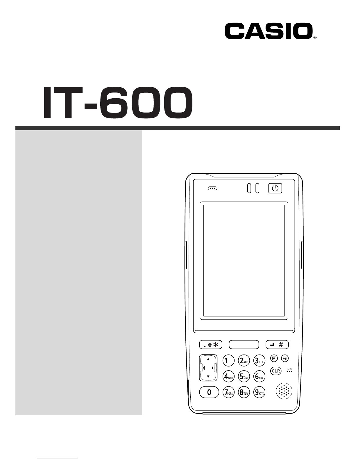
Handheld Terminal
User’s Guide
Series
Be sure to read “Safety
Precautions” inside this
guide before trying to use
your Handheld Terminal.
After reading this guide,
keep it in a safe place for
future reference.
E
Page 2
• This Product is equipped with the Brycen BL-RAPPORE Stack and My Wirefree
Network Bluetooth User Interface Application, the use of which is governed by a license
granted by Brycen Co., Ltd.
• BLUETOOTH is a registered trademark owned by Bluetooth SIG, Inc. and licensed to
CASIO COMPUTER CO., LTD.
• Microsoft and Windows are either registered trademarks or trademarks of Microsoft
Corporation in the United States and/or other countries.
Information in this document is subject to change without advance notice. CASIO Computer Co.,
Ltd. makes no representations or warranties with respect to the contents or use of this manual and
specifically disclaims any express or implied warranties of merchantability or fitness for any
particular purpose.
An electronic version of this guide in PDF is also available at;
world.casio.com/system/pa/UsersGuide/sup85_e.html
Page 3

E-1
Warning
Caution
Danger
Safety Precautions
Congratulations upon your selection of this CASIO product. Be sure to read the
following Safety Precautions before trying to use it for the first time.
Markings and Symbols
The following are the meanings of the markings and symbols used in these Safety
Precautions.
This symbol indicates information that, if ignored or applied
incorrectly, creates the danger of death or serious personal injury.
This symbol indicates information that, if ignored or applied
incorrectly, creates the possibility of death or serious personal
injury.
This symbol indicates information that, if ignored or applied
incorrectly, creates the possibility of personal injury or property
damage.
• A diagonal line indicates something you should not do. The symbol shown
here indicates you should not try to take the unit apart.
• A black circle indicates something you should do. The symbol shown here
indicates you should unplug the unit from the wall outlet.
Precautions During Use
Warning
Disassembly and Modification
• Never try to disassemble or modify the Handheld Terminal and its options in
any way. High voltage inside creates the danger of electric shock.
Abnormal Conditions
• Should the Handheld Terminal and its options become hot or start to emit
smoke or a strange odor, immediately turn off the power, and contact your
original vendor or an authorized CASIO service provider. Continued use
creates the danger of fire and electric shock.
Page 4
E-2
Warning
Foreign Objects
• Should any foreign matter get into the Handheld Terminal and its options,
immediately turn off the power and contact your original vendor or an
authorized CASIO service provider. Continued use creates the danger of fire
and electric shock.
Dropping and Damage
• Should you drop the Handheld Terminal and its options and damage them,
immediately turn off the power and contact your original vendor or an
authorized CASIO service provider. Continued use creates the danger of fire
and electric shock.
Moisture
• Though the Handheld Terminal is water splash-resistant, its optional
peripherals are not. Keep loose metal objects and containers filled with
liquids away from your Handheld Terminal and the optional peripherals.
Also, never connect or disconnect peripherals to the Handheld Terminal
while they are wet. Water getting into the Handheld Terminal or its
peripherals creates the danger of fire and electric shock.
LED Light
• This product scans bar codes using LED light. Never look directly into the
LED light or shine the LED light into the eyes.
Warning!
Interference with the Operation of Other Equipment
(Using Wireless Data Communication)
• Keep your Handheld Terminal at least 22 centimeters (811/16") away from
anyone wearing a pacemaker. Radio waves emitted by the Handheld
Terminal can affect the operation of a pacemaker.
• In order to protect someone wearing a pacemaker from the risk of
unintentional interference, turn off the Handheld Terminal before boarding a
crowded train or entering any other crowded area.
Page 5
E-3
Caution
Foreign Objects
• Take care to ensure that metals or combustible objects are not inserted into
the openings of the Handheld Terminal and its options. Such the objects
inside of the Handheld Terminal create the danger of fire and electric shock.
Location
• Do not locate the Handheld Terminal and its options on a surface that is
unstable or uneven. Doing so creates the danger of the Handheld Terminal
falling, which can cause personal injury.
• Do not locate the Handheld Terminal and its options in an area subject to
large amounts of humidity or dust. Doing so creates the danger of fire and
electric shock.
• Do not leave the Handheld Terminal and its options for a long period in a car
parked in direct sunlight.
Heavy Objects
• Never place heavy objects on top of the Handheld Terminal and its options.
Doing so creates the danger of loss of balance and the objects falling, which
can cause personal injury.
LCD Screen
• Never apply strong pressure to the screen or subject it to strong impact.
Doing so can crack the screen or LCD panel glass, which can cause the
danger of personal injury.
• Should the LCD panel glass break, never touch the liquid inside. Doing so
can cause skin inflammation.
– Should liquid from the LCD panel accidentally get into your mouth,
immediately wash your mouth with water and then consult a physician.
– Should liquid from the LCD panel accidentally get into your eyes or onto
your skin, immediately rinse for at least 15 minutes with clean tap water
and then consult a physician.
Page 6
E-4
Optional Lithium-ion Battery Pack
Danger
• Never allow the battery pack to become wet. Water can create the danger of
battery pack heat emission, explosion, and fire.
• Never use or leave the battery pack next to open flame, near a stove, or any
other area exposed to high heat. Doing so creates the danger of battery pack
heat emission, explosion, and fire.
• Never use the battery pack with any device other than the Handheld
Terminal. Doing so can create the danger of battery pack heat emission,
explosion, and fire.
• Note that the battery pack’s positive (+) and negative (–) polarities must be
oriented correctly when it is loaded into battery charger or the Handheld
Terminal. Connecting the battery pack with its polarities reversed creates the
danger of battery pack fluid leakage, heat emission, explosion, and fire.
• Never dispose of the battery pack by incinerating it or otherwise expose it to
heat. Doing so creates the danger of battery pack heat emission, explosion,
and fire.
• Never allow the positive (+) and negative (–) terminals of the battery pack to
become connected (shorted) by metal. Doing so creates the danger of battery
pack heat emission, explosion, and fire.
• Never transport or store the battery pack together with a necklace, hair pins
or other metal objects. Doing so can short battery pack terminals, creating
the danger of battery pack heat emission, explosion, and fire. Be sure to
place the battery pack in its case whenever transporting or storing it.
• Never throw the battery pack or otherwise subject it to strong impact. Doing
so creates the danger of battery pack heat emission, explosion, and fire.
• Never pierce the battery pack with nails, hit it with a hammer, or step on it.
Doing so can create the danger of battery pack heat emission, explosion, and
fire.
• Never try to take apart the battery pack or modify it in any way. Doing so
creates the danger of battery pack heat emission, explosion, and fire.
• Use only the specified battery charger to charge the battery pack. Use of
other type of battery charger creates the danger of battery pack heat
emission, explosion, and fire.
Page 7
E-5
Warning
• Never place the battery pack in a microwave oven or any other high-voltage
device. Doing so creates the danger of battery pack heat emission,
explosion, and fire.
• Should the battery pack emit a strange odor or heat, change color or shape, or
exhibit any other abnormal behavior, immediately stop using it. Continued
use creates the danger of battery pack heat emission, explosion, and fire.
• If the amount of time period the battery pack can serve becomes
considerably short, stop using it. It may indicate the possibility of a
malfunction in the battery pack. Continued charging the battery pack creates
the danger of heat emission, explosion, and fire.
• If the battery pack does not achieve full charge after the normal charging
time has passed, stop charging it. Continued charging creates the danger of
battery pack heat emission, explosion, and fire.
• Should the battery pack start to leak or emit a strange odor, immediately
move it away from any nearby flame. Leaking battery fluid is combustible,
and exposure to flame creates the danger of explosion and fire.
• Should fluid from the battery pack accidentally get into your eyes, do not
rub them. Immediately rinse your eyes with clean tap water and then
consult a physician immediately.
Caution
• Never use or leave the battery pack in an area exposed to direct sunlight, in
a car parked in direct sunlight, or any other very hot area. Doing so creates
the danger of heat emission and fire, as well as deterioration of battery pack
performance and shortening of its service life.
• Do not use the battery pack in areas where static electricity is being
generated. Doing so creates the danger of battery pack heat emission,
explosion, and fire.
• Danger of explosion if the battery pack is incorrectly replaced.
Replace only with same or equivalent type recommended by CASIO.
Dispose of used batteries according to the local regulation.
• Should fluid from the battery pack accidentally get onto clothing or your
skin, immediately rinse it off with clean tap water. Prolonged contact with
battery pack fluid can cause skin irritation.
• Keep the battery pack out of the reach of small children. Do not let small
children remove the battery pack from battery charger or the Handheld
Terminal while it is powered on.
Page 8
E-6
AC Power Supply
Warning
• Do not use the Handheld Terminal at a voltage other than the specified
voltage. Also, do not connect the Handheld Terminal to a multi-plug power
strip. Doing so creates the danger of fire and electric shock.
• Avoid conditions that can cause damage or breaks in the power cord. Do not
place heavy objects on the power cord and keep it away from sources of
heat. Any of these conditions can damage the power cord, creating the
danger of fire and electric shock.
• Never modify, sharply bend, twist, or pull on the power cord. Doing so
creates the danger of fire and electric shock.
• When using the battery chargers and the cradles, be sure to use the
respective AC adaptors (sold separately). Use of other AC adaptor model
creates the danger of fire and electric shock.
• Should the power cord become severely damaged (to the point that wires are
exposed or broken), contact an authorized CASIO service provider about
repair or replacement. Use of a damaged electrical cord creates the danger of
fire and electric shock.
Caution
• Keep the power cord away from stoves and other sources of extreme heat.
Heat can melt the covering of the power cord and create the danger of fire
and electric shock.
• Never pull on the power cord when unplugging it. Doing so can damage the
cord and create the danger of fire and electric shock. (Always hold the plug
when unplugging it from the wall outlet.)
• Never touch the plug while your hands are wet. Doing so can create the
danger of electric shock.
• Be sure to unplug the power cord from the wall outlet before moving the
battery chargers and the cradles. Failure to do so can result in damage to the
power cord caused by pulling it, which creates the danger of fire and electric
shock.
• Be sure to unplug the power cord from the wall outlet before cleaning the
battery chargers and the cradles.
• Be sure to unplug the power cord after use.
• Unplug the power cord from the wall outlet whenever leaving the battery
chargers and the cradles unattended for a long period.
Page 9
E-7
AC Adaptor
Caution
• The housing of the AC adaptor can become warm during normal use.
• Take normal precautions against electric shock.
• At least once a year, unplug the AC adaptor from the wall outlet and clean
any dust that builds up between the prongs of the plug.
Dust built up between the prongs can lead to the danger of fire.
Backup Copies of All Important Data
Caution
• Note that CASIO Computer Co., Ltd. shall not be held liable to you or any
third party for any damages or loss caused by deletion or corruption of data
due to use of the Handheld Terminal, malfunction or repair of the Handheld
Terminal or its peripherals, or due to the batteries going dead.
• The Handheld Terminal employs electronic memory to store data, which
means that memory contents can be corrupted or deleted if power is
interrupted due to the batteries going dead or incorrect battery replacement
procedures. Data cannot be recovered once it is lost or corrupted. Be sure to
make backup copies of all important data. One way to do this is to use the
separately sold Cradles to transfer data to a computer.
Page 10

E-8
Operating Precautions
Your Handheld terminal and its options are precision. Improper operation or rough
handling can cause problems with data storage and other problems. Note and observe
the following precautions to ensure proper operation.
• Do not continue operating the Handheld Terminal when battery power is low.
Doing so can cause data to be lost. When the battery goes low, charge it as soon as
possible.
• Do not leave dead battery pack in the Handheld Terminal for a long period.
Dead battery pack can leak, leading to malfunction and damage to the Handheld
Terminal.
• Use the Handheld Terminal and its options only within the specified
temperature range.
Use outside of the specified temperature range creates the risk of malfunction.
• Avoid using the Handheld Terminal and its options in areas subject to the
following conditions.
The following conditions create the risk of damage to the Handheld Terminal.
— Large amounts of static electricity
— Extreme heat or extreme cold
— High humidity
— Sudden temperature extremes
— Large amounts of dust
• Use only the dedicated stylus that comes with the Handheld Terminal to operate
its touch screen and reset switch.
• Do not use any tool other than the dedicated stylus to operate the touch screen.
Other tools can scratch the touch screen and lead to malfunction.
• Never use thinner, benzene, cosmetic cleaning fluids, or other volatile agents to
clean the Handheld Terminal.
To clean the Handheld Terminal, wipe it with a dry cloth, or a cloth moistened in
a weak solution of water and a mild neutral detergent. Wring all excess moisture
from the cloth before wiping.
• Although the Handheld Terminal meets the IP54 level of the International
Standard IEC529, pay your attention to the following when using it in the rain.
— After a large amount of rain or water falls on the Handheld Terminal, wipe off it
immediately.
— Do not use it in the rain for a long period of time.
— Make sure the battery cover and connect cover are closed securely before using it.
— Do not press on the touch screen or keys with excessive force when using it in the
rain.
Page 11

E-9
Important
• The contents of this guide are subject to change without notice.
• Note that CASIO COMPUTER CO., LTD. shall not be held liable to you or any third
parties for any losses or damages arising from the use of this guide.
• This guide does not include any information about programming and download
procedures. See the applicable separate documentation for information about the
procedures.
After Service
• Should this product ever malfunction, contact your original retailer providing
information about the product name, the date you purchased it, and details about the
problem.
GUIDELINES LAID DOWN BY FCC RULES FOR USE OF THIS UNIT IN THE U.S.A. (not
applicable to other areas).
NOTICE
This equipment has been tested and found to comply with the limits for a Class B digital device, pursuant
to Part 15 of the FCC Rules. These limits are designed to provide reasonable protection against harmful
interference in a residential installation. This equipment generates, uses and can radiate radio frequency
energy and, if not installed and used in accordance with the instructions, may cause harmful interference
to radio communications. However, there is no guarantee that interference will not occur in a particular
installation. If this equipment does cause harmful interference to radio or television reception, which can
be determined by turning the equipment off and on, the user is encouraged to try to correct the interference
by one or more of the following measures:
• Reorient or relocate the receiving antenna.
• Increase the separation between the equipment and receiver.
• Connect the equipment into an outlet on a circuit different from that to which the receiver is connected.
• Consult the dealer or an experienced radio/TV technician for help.
FCC WARNING
Changes or modifications not expressly approved by the party responsible for compliance could void the
user’s authority to operate the equipment.
Proper connectors must be used for connection to host computer and/or peripherals in order to meet FCC
emission limits.
Caution Exposure to radio frequency radiation (below is for portable device)
To comply with FCC RF exposure compliance requirements, this device must not be co-located or
operating in conjunction with any other antenna or transmitter.
Page 12

E-10
Declaration of Conformity
Model Number: HA-D60IO
Trade Name: CASIO
Responsible party: Casio America, Inc. Industrial Handheld Division
Address: 2700 Augustine Drive Suite 155, Santa Clara, California 95054
Telephone number: 408-737-6300
This device complies with Part 15 of the FCC Rules. Operation is subject to the following two conditions:
(1) This device may not cause harmful interference, and (2) this device must accept any interference
received, including interference that may cause undesired operation.
For Customers in Canada
This Class B digital apparatus complies with Canadian ICES-003.
Cet appareil numériqué de la classes B est conformé à la norme NMB-003 du Canada.
This device complies with RSS 210 of Industry Canada (IC).
Operation is subject to the following two conditions:
(1) this device may not cause interference, and
(2) this device must accept any interference, including interference that may cause undesired operation
of this device.
L’ utilisation de ce dispositif est autorisée seulement aux conditions suivantes :
(1) il ne doit pas produire de brouillage et
(2) I’ utilisateur du dispositif doit étre prêt à accepter tout brouillage radioélectrique reçu, même si ce
brouillage est susceptible de compromettre le fonctionnement du dispositif.
Exposure to radio frequency radiation
The installer of this radio equipment must ensure that the antenna is located or pointed such that it does
not emit RF field in excess of Health Canada limits for the general population;
consult Safety Code 6, obtainable from Health Canada's website at www.hc-sc.gc.ca/rpb.
Regulatory Information
The CASIO IT-600M30U and IT-600M30UC models are designed, tested and found to meet the
relevant regulatory standards described below.
Regulatory standards: UL60950-1
FCC Part 15B
FCC Part 15C
RSS-GEN
RSS-210
Page 13

E-11
Contents
Safety Precautions.........................................................................................E-1
Operating Precautions...................................................................................E-8
Important.........................................................................................................E-9
Checking in the Box.....................................................................................E-13
Handheld Terminal System Configuration .................................................E-14
General Guide...............................................................................................E-17
Loading and Removing the Battery Pack ..................................................E-19
Loading ............................................................................................................. E-20
Removing.......................................................................................................... E-21
Attaching the Neck Strap ............................................................................E-23
Attaching the Touch Screen Protective Sheet ...........................................E-24
Configuring Handheld Terminal Settings...................................................E-25
Calibrating Touch Screen Alignment................................................................ E-25
Adjusting Display Brightness ........................................................................... E-26
Display Auto Dimmer....................................................................................... E-26
Using the Linear Imager ..............................................................................E-27
Handling miniSD Cards ...............................................................................E-28
Installing ........................................................................................................... E-28
Removing.......................................................................................................... E-29
Performing Communications ......................................................................E-30
IR Communication ........................................................................................... E-30
Bluetooth® Communication .............................................................................. E-31
Page 14

E-12
Resetting the Handheld Terminal................................................................ E-32
Performing a Full Reset (Initialization) ............................................................ E-33
IT-600 Specifications .................................................................................... E-34
USB Cradle (HA-D60IO) ............................................................................... E-36
General Guide ................................................................................................... E-36
Connecting the USB Cradle Power Supply ...................................................... E-38
USB Cradle (HA-D60IO) Specifications ......................................................... E-40
Using the Cradle-type Charger (HA-D30CHG) ........................................... E-41
General Guide ................................................................................................... E-41
Connecting the AC Adaptor for Cradle-type Charger ...................................... E-43
Cradle-type Charger (HA-D30CHG) Specifications ........................................ E-44
Using the Dual Battery Charger (HA-D32DCHG) ....................................... E-45
General Guide ................................................................................................... E-45
Charging a Battery Pack ................................................................................... E-47
Connecting Multiple Dual Battery Chargers .................................................... E-48
Dual Battery Charger (HA-D32DCHG) Specifications ................................... E-49
Using Rechargeable Battery Pack ..............................................................E-50
Battery Pack Specifications .............................................................................. E-50
Large-capacity Battery Pack Specifications ..................................................... E-50
Using CF Card Extension Unit (HA-D94CFU2) .......................................... E-51
CF Card Extension Unit Specifications ............................................................ E-51
Attaching the Unit ............................................................................................ E-51
Using Hand Belt (HA-D95HB2) ....................................................................E-53
Attaching the Hand Belt ................................................................................... E-53
Page 15
E-13
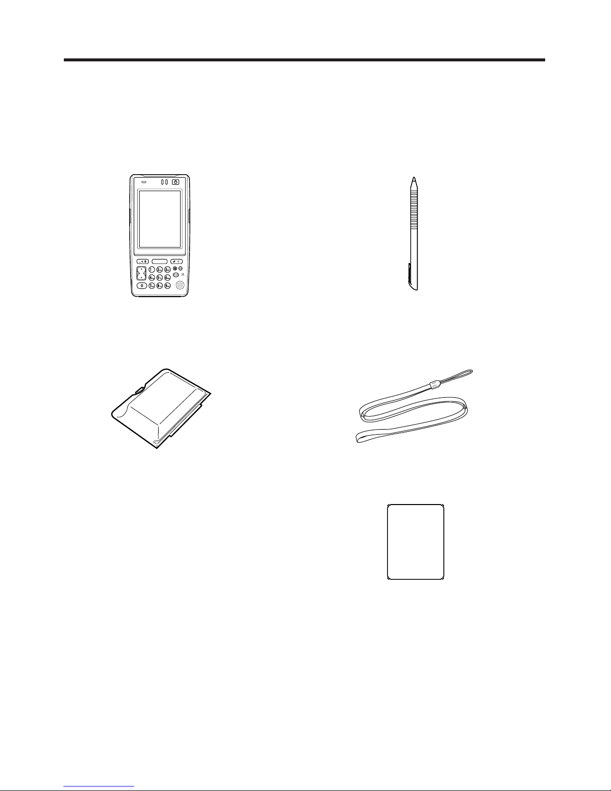
Checking in the Box
Please check the contents of the box before using the Handheld Terminal for the first
time.
Open the box and make sure that all the items shown here are included.
Handheld T erminal Stylus
Neck Strap
Touch Screen Protective SheetUser's Guide (this manual)
Large-capacity battery
pack cover
Page 16
E-14
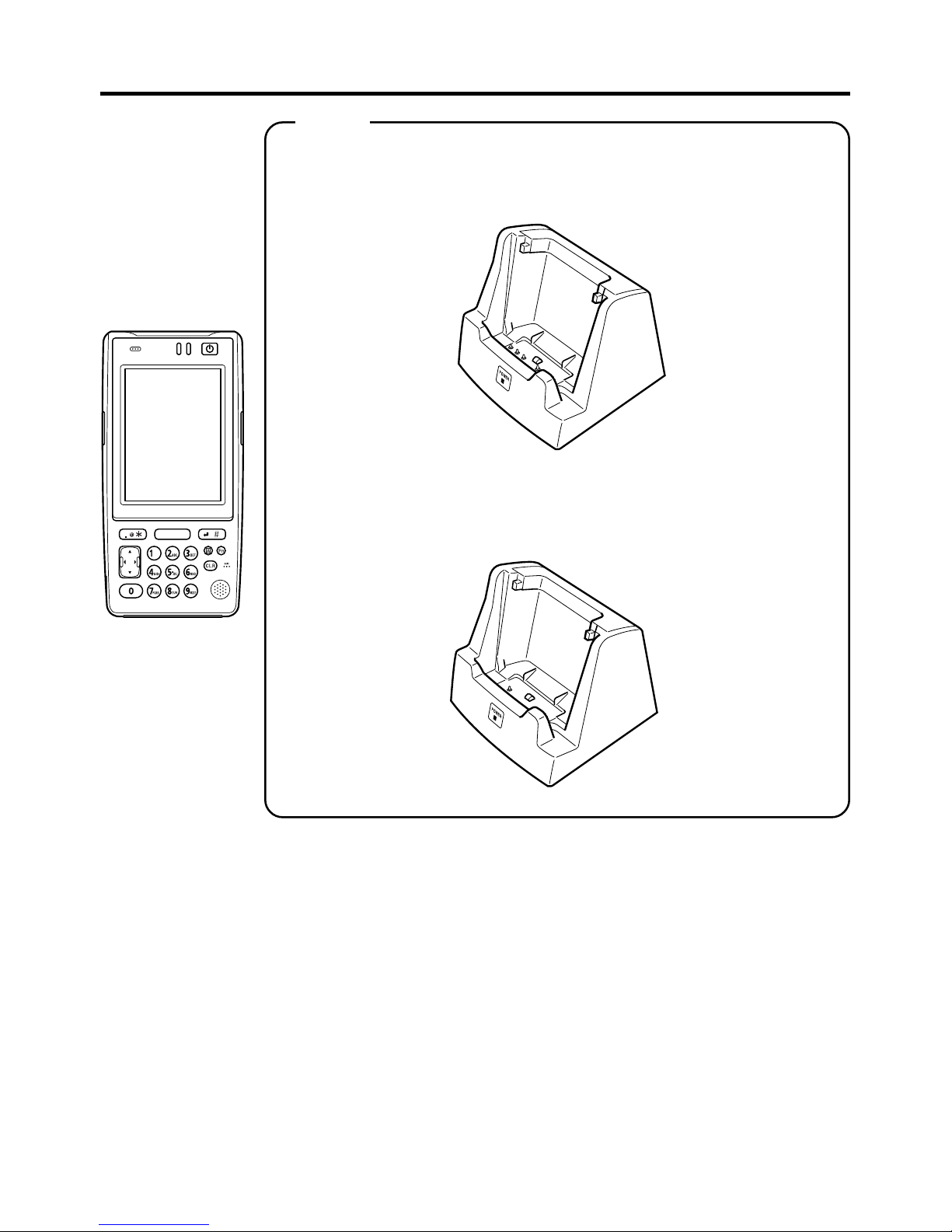
Handheld Terminal System Configuration
Options
USB Cradle
Ethernet Cradle
Cradle-type Charger
HA-D30CHG
IT-600 Series
HA-D60IO
HA-D62IO
Page 17
E-15
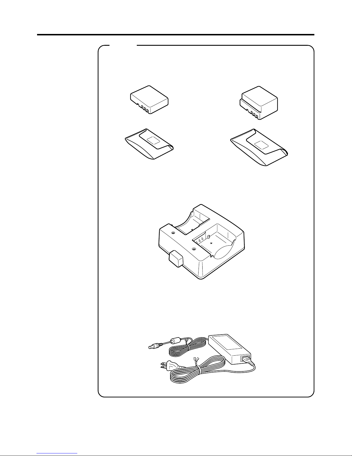
HA-D20BAT
(Battery Pack)
HA-D21LBAT
(Large-capacity Battery Pack)
Dual Battery Charger
HA-D32DCHG
Battery Pack
AC Adaptor for Dual Battery Charger/
USB Cradle and Ethernet Cradle
AD-S42120BE
Options
Page 18

E-16
Cable
DT-380USB
AC Adaptor for Cradle-Type Charger
AD-S15050BE
CF Card Extention Unit
HA-D94CFU2
Options
Hand Belt
HA-D95HB2
Page 19

E-17
1
2
3
4
5
6
7
8
9
10
11
General Guide
Left Front Right Back
Buzzer
Indicator 1
Indicator 2
Power Key
Touch Screen
Center Trigger Key
Execute Key
Text Key
Fn Key
CLR Key
Numeric Keys
Sounds a buzzer.
Orange: Charging
Green: Charging complete
Red: Battery pack error or outside charging temperature range
Flashes in blue when operating via Bluetooth. Lights in green
when reading a bar code successfully.
Turns the power on and off.
Displays text and operating instructions. Also used to operate the
Handheld Terminal and enter data using the stylus provided.
Used to perform bar code reading. Can be assigned an arbitrary
function.
Press when finishing entering numerical values or when moving
to the next step.
Press when switching to the text input mode.
Used to make various settings in combination with the numeric
keys or when starting a pre-registered application.
Used to clear one letter to the left of the input key.
Used to enter numbers or letters.
16
19
7
8
9
6
13
14
20 11 10
12
5
4
1 18 32
23
17
15
26
22
27
25
28
29
24
21
23
Page 20

E-18
12
13
14
15
16
17
18
19
20
21
22
23
24
25
26
27
28
29
Cursor Key
Microphone
Speaker
Trigger R Key
Trigger L Key
Headset Jack
Barcode Reader Port
IR Port
Cradle Terminal
Digital Camera (IT600M30UC only)
LED Light
Strap Holes
Expansion Port
Reset Switch
miniSD Card Slot
Battery Pack Cover
Battery Pack Cover
Lock Switch
Cradle Mount
Holes
Performs the same functions as the up, down, left and right arrow
keys on a PC keyboard.
Used to input a sound including voice.
Alarms and voice messages are output here. Voice messages are
not output from the speaker when a headset is connected to the
headset jack. (The sound of the camera shutter is always output
from the speaker.)
Used to perform bar code reading.
Used to perform bar code reading.
A separately sold headset can be connected here.
LED light is emitted from this window that reads barcodes.
Used for communication with another Handheld Terminal.
Used to communicate with and to receive power provided by the
USB Cradle or Ethernet Cradle.
Used to capture photographs, images.
Used to light up an object when capturing with the Digital
Camera.
Used to attach the strap.
Provided for future expansion.
Used to reset the Handheld Terminal.
Provided for installing a miniSD card by removing the battery
pack.
Used to cover the battery compartment that holds the battery
pack inside.
Used to lock the battery cover and to release.
Used to mount the Handheld Terminal to the separately sold USB
Cradle or Ethernet Cradle.
Page 21

E-19
Loading and Removing the Battery Pack
Your Handheld Terminal uses two types of battery: a battery pack and a memory
backup battery.
The battery pack is used to power normal operations and to store data, while the
memory backup battery provides the power required to maintain memory contents
when the battery pack power is unable to supply power for some reason.
The operating power is supplied by a battery pack. You can choose between a battery
pack
(HA-D20BAT) and a large-capacity battery pack (HA-D21LBAT).
The backup battery is installed inside of the Handheld Terminal.
This guide uses the following terms to refer to the batteries.
Battery Pack: Rechargeable battery pack (HA-D20BAT or HA-D21LBAT) for
normal operations and data storage
Backup Battery: Built-in battery for memory backup
When the battery pack power goes low, immediately charge it or replace it with a
charged battery pack.
You can use the Dual Battery Charger, the Cradle-type Charger, the USB Cradle, or the
Ethernet Cradle to charge a battery pack. See the sections of this guide that cover these
chargers and cradles for information about how to use them for charging.
Important!
Always keep backup copies of all important data!
• The battery pack powers normal operation and also provides power required to
maintain memory contents, while the backup battery provides backup power to
maintain memory contents. Because of this, you should not remove the battery
pack if the backup battery is dead. Removing the battery pack while the backup
battery is dead causes data in the memory to be corrupted or lost. Note that
once data is lost it cannot be recovered. Always keep separate backup copies of
all important data.
• The charge of a battery pack when you purchase it may be depleted due to
testing at the factory or natural discharge during shipment and storage. Be sure
to charge the battery pack before you use it.
• The life of a battery pack is limited, and charging a battery pack causes it to
gradually lose its ability to maintain the charge. If your battery pack seems to
require charging very frequently, it probably means it is time to purchase a new one.
• A fully charged backup battery can maintain memory (RAM) contents for about
10 minutes, even when the battery pack is removed.
• The backup battery achieves a full charge in about four days when the battery
pack is loaded.
Page 22

E-20
Loading
1.Turn over the Handheld Terminal.
2.Slide the battery pack lock switch to the "FREE" position, and then remove the
battery pack cover.
3.Load a battery pack (HA-D20BAT) or large-capacity battery pack (HA-D21LBAT).
Take care that the battery pack is oriented correctly when you load it. In addition,
load the battery back while making sure that the end of the battery pack removal tape
is protruding above the battery pack.
4.Put back the battery pack cover as shown in the diagram and then return the battery
pack cover switch to the “LOCK” position. When loading a large-capacity battery
pack, use the large-capacity battery pack cover instead of the battery pack cover.
1
2
3
Page 23

E-21
Removing
1.Make sure that the Handheld Terminal is turned off.
If the power is on, press the power key to turn it off.
2.Turn over the Handheld Terminal.
3.Turn the battery pack lock switch on the back of the Handheld Terminal to the
"FREE" position, and then remove the battery pack cover.
4.Remove the battery pack by pulling up the removal tape as shown in the illustration.
Page 24

E-22
Loading the large-capacity battery pack into the Handheld Terminal
After loading the large-capacity battery pack, you need to use the special large-capacity
battery pack cover in place of the standard battery pack cover.
“Loading and Removing” of the large-capacity battery pack cover are the same as those
for the standard battery pack cover.
1
2
3
Important!
• When removing the battery pack, make sure you do not leave the Handheld
Terminal without a battery pack for more than about 10 minutes. Doing so can
cause data in the memory to be deleted.
• When removing the battery pack, be sure you carefully follow the proper
procedure as explained in this guide.
• Never try to use other type of battery than the ones that are specified for this
product.
• When removing the battery pack, pull the removal tape straight up and remove
the battery pack. Removing with excessive force can damage the battery pack.
Page 25

E-23
Attaching the Neck Strap
The neck strap can be used to prevent the Handheld Terminal from dropping when
carrying it around. Since there are two strap holes where the neck strap can be attached,
use the hole that affords the greatest ease of use. Attach the neck strap according to the
procedure described below.
To attach the neck strap
1. Pass the thin cord of the neck strap through the neck strap hole on the back of the
Handheld Terminal.
2. Pass the other end of the strap (the part you put around your neck) through the loop
formed by the thin cord.
Important!
Do not swing the Handheld Terminal around holding the neck strap.
Page 26

E-24
Attaching the Touch Screen Protective Sheet
Attach the touch screen protective sheet according to the procedure described below.
Important!
Do not press on the touch screen with excessive force when attaching the touch
screen protective sheet. This can damage the touch screen.
1.Switch the power of this unit OFF and remove any dust or other debris from the
touch screen.
Front
2.Peel off the film (green) affixed to the front of the protective sheet.
• If you have difficulty in peeling off the film, use a piece of cellophane tape. (After
cutting a piece of cellophane tape to a suitable length, hold onto one end of the piece
of cellophane tape and press the adhesive side of the other end of the tape onto the
green film. The film can be peeled off easily by pulling up the tape.)
• The opposite of the surface where the film was affixed is the surf ace that is faced to
the touch screen.
3.With its front side (the side to which the film was attached) towards you, fix the
upper and lower sides of the protective sheet properly to the touch screen. If you
encounter difficulties fixing it properly, carefully bend the slight projections at the
four corners of the protective sheet to the front.
• Be careful so that dust and other debris is not allowed to get between the touch screen
and the protective sheet. Using the Handheld Terminal with dust or other debris
trapped between the touch screen and protective sheet can damage the touch screen.
Page 27

E-25
Configuring Handheld Terminal Settings
Calibrating Touch Screen Alignment
Whenever the response of the touch screen is poor, or the operations being executed do
not match with the location you are tapping on the touch screen, please recalibrate the
alignment of the touch screen using the following method.
• Press the “Fn” key and then press the “4” key after confirming that “F” is displayed
in the lower right corner of the screen. The following screen is displayed.
∗ The following screen can also be displayed by accessing the menus and tab in order
of Start ➝ Settings ➝ Stylus ➝ Calibration.
• Press the stylus against the center of the target mark (+ mark) as indicated on the
screen. The screen shown below appears after you press the stylus against the target
at five different locations.
• Press the Execute key or tap anywhere on the touch screen.
Page 28

E-26
Adjusting Display Brightness
You can use the following procedures to adjust display brightness to make it easier to
read under different lighting conditions.
• Press the “Fn” key and then press the “5” key or “6” key after confirming that “F” is
displayed in the lower right corner of the screen. Pressing the “5” key adjusts
brightness for a darker display, while pressing the “6” key adjusts brightness for a
lighter display.
∗ In order to continue to make adjustments, press the “5” key or “6” key after again
first pressing the “Fn” key.
∗ Brightness settings can also be made by accessing the menus and tab in order of Start
➝ Settings ➝ Brightness ➝ Brightness (Battery) or Brightness (External).
Display Auto Dimmer
The display auto dimmer automatically lowers display brightness if you do not perform
any operation for a specific period of time. This helps the battery power to be
conserved.
You can use the following procedure to specify a period of time that should be allowed
to elapse until when the auto dimming is initiated.
• Access the menus and tab in order of Start ➝ Settings ➝ Brightness ➝ Backlight.
Page 29

E-27
Using the Linear Imager
1.After turning on the power, position the reader port close to a bar code and then press
the trigger key.
2.The LED emits light and scans the bar code. When scanning is completed normally,
Indicator 2 displays a green light and a buzzer sounds.
Important!
• If you are unable to scan a bar code, try changing the angle at which the
Handheld Terminal is held or distance between the reader port and the bar
code, and then try scanning again.
• This Handheld Terminal is capable of scanning bar codes at a distance of
about 60-300 mm (2
6
/16"-1113/16"). Furthermore, the distance at which
scanning is possible may vary according to the bar code symbology.
Warning!
■ Never look directly into the LED light.
• This product scans using LED light. Never look directly into the LED light
or shine the LED light into the eyes.
About the Class 1 LED Label
• This label identifies the Handheld Terminal as a Class 1 LED product under
IEC60825-1 (ed.1.2)
Page 30

E-28
Handling miniSD Cards
The Handheld Terminal supports miniSD card.
Since the miniSD card slot is located inside the battery pack compartment, first remove
the battery pack when installing or removing a miniSD card.
Refer to pages 20 to 23 for information on “Loading and Removing the battery pack”.
Install (or replace) a miniSD card according to the procedure described below.
Installing
1. Check that the power is turned off. If the power is on, always make sure to turn it off
by pressing the Power Key.
2. Remove the battery pack.
3. Insert the miniSD card with the top of the card (containing lettering) facing up by
properly aligning with the slot.
• Although some resistance may be felt when the card is inserted, gently insert the card
all the way into the slot until it contacts the back of the slot.
• Do not push in the card on the angle.
4. Load the battery pack.
Page 31

E-29
Removing
1. Check that the power is turned off.
If the power is on, always make sure to turn it off by pressing the Power Key.
2. Remove the battery pack.
3. Push on the card. Slowly remove the card after it slightly pops out.
PressPress
4. Load the battery pack.
Important!
• A miniSD card must be inserted with the top and bottom properly aligned and
in the proper direction. Attempting to insert it with an excessive force in the
incorrect orientation can risk damage to the connectors and slot. Be careful
when inserting a miniSD card.
• The battery pack will not be able to be properly installed if the miniSD card is
not properly installed. Reinstall the miniSD card properly if this happens.
• Since data recorded in the Handheld Terminal may be lost if the battery pack is
removed for more than 10 minutes, complete the installation (or removing) of
miniSD card within 10 minutes.
Page 32

E-30
Performing Communication
IR Communication
IR communication can be used to transfer data between two Handheld Terminals.
When performing IR communication, orient the IR ports of both Handheld Terminals
so they are pointing directly at each other.
The ports can be in direct contact with each other, or they can be separated by up to 1
meter (
3'3
1
Ú
2
") (up to 30cm (11
13
Ú
16
") for 4Mbps communication speed).
Important!
• A high-sensitivity communication element is used during IR communication.
• In order to ensure successful communication, avoid using cellular phones or
other devices that emit radio wave in the area where you are performing IR
communication.
• If you need to use such a device, move away from the communicating Handheld
Terminals. In case of a cellular phone, keep it at least 30cm (
11
1313
1313
13
ÚÚ
ÚÚ
Ú
1616
1616
16
") away.
Page 33

E-31
Bluetooth® Communication
Bluetooth® interface can also be used to transfer data between two Handheld Terminals.
With Bluetooth
®
the two Handheld Terminals should be located within about three meters
(9
'103⁄8") from each other, as long as there is nothing blocking the path between them.
Important!
Observe the following precautions to help ensure that Bluetooth communication is
successful.
• Make sure two Handheld Terminals face each other within three meters
(9
'103⁄8"). An obstacle if any between the Handheld Terminals may cause a
shorter communication range.
• Make sure there is at least two meters (6' 7") between the Handheld Terminal
and other equipment (electrical appliances, audio-visual equipment, OA
equipment, and digital cordless telephones, facsimile machines, etc.). (Take
special care with microwave ovens. Allow at least three meters (9' 10
3
⁄
8
) between
the Handheld Terminals in wireless operation and a microwave oven.) When
approaching such a device when its power is turned on, proper communication
may prove impossible while this may also cause interference with TV and radio
reception (images produced by certain UHF and broadcast satellite channels
may become blurry).
• Normal communication may not be possible in an area near a broadcast
transmitter or wireless transmitter. If this happens, move to a different location.
Normal communication may not be possible in areas exposed to strong radio
waves.
• RF Wireless LAN Interference
Because Bluetooth
®
and RF wireless LAN use the same frequency band
(2.4GHz), radio interference can occur if there is a wireless LAN device nearby.
This can result in lower communication speeds, or even make it impossible to
establish a connection. If this happens, try the following countermeasures.
• Move at least 10 meters (32
'103⁄4") away from the wireless LAN device.
• If you cannot keep the distance at least 10 meters (32
'103⁄4") or more between the
Handheld Terminal and a wireless LAN device, turn off the power of either the
Handheld terminal or the wireless LAN device.
• Although the Handheld Terminal enables wireless LAN and Bluetooth
®
communication to be used simultaneously as a result of being equipped with
Bluetooth
®
Ver. 1.2, communication may not be possible depending on the
surrounding radio wave environment.
Page 34

E-32
Resetting the Handheld Terminal
Resetting the Handheld Terminal is the same as restarting a computer. Performing a
reset causes all unsaved inputs and edits to be lost, but data that is already stored in the
memory as well as all settings should be unaffected.
Use reset to restore normal operation whenever the Handheld Terminal operates
abnormally due to misoperation or some other reason.
Use the stylus to press the reset switch on the back of the Handheld Terminal.
This starts the reset operation.
If reset does not find a memory problem
The Handheld Terminal restarts, and normal operation is restored.
If reset finds a memory problem
A message like the one shown below appears on the display when the reset operation
discovers a memory problem.
When this message appears, press the Trigger key to continue with the reset operation.
Note, however, that reset may not be successful depending on the condition of the
memory. In this case, perform the full reset operation described on the next page.
Trigger R
Key
Page 35

E-33
Performing a Full Reset (Initialization)
Performing a full reset initializes memory. This means that all data stored in the
memory (RAM) is deleted and all the settings are returned to their initial factory
settings.
Perform a full reset whenever any one of the following conditions exists.
• When you want to delete all memory contents and return the settings to their initial
factory settings.
• When you are no longer able to use the Handheld Terminal because you forgot your
password.
• When the Handheld Terminal does not operate normally due to a memory problem.
• When the message “A problem with memory contents has been found. ...” appears.
To perform a full reset
Important!
Performing a full reset deletes all data currently stored in the memory (RAM). If
possible, backup data of the Handheld Terminal to a computer, Flash Memory, a
memory card, or some other medium before performing a full reset.
1.Hold down the power key and the CLR key while pushing down the reset button for
about 1 second with the stylus until the message shown below appears on the display.
• To cancel the full reset operation, press the Trigger L key.
2.Press the Trigger R key. This causes the message shown below to appear.
• To cancel the full reset operation, press the Trigger L key.
3.Press the Trigger R key again.
• Full reset is performed, all data in the memory (RAM) are erased and the start-up
screen is displayed.
Trigger R
key
Trigger R
key
Page 36

E-34
IT-600 Specifications
Model: IT-600M30U, IT-600M30UC
CPU: Marvell
®
PXA270 520MHz
Memory: 64MB RAM, 128MB Flash ROM (user defined: 60MB)
OS: Microsoft® Windows® CE5.0 operating system,
English Version
Display: 3.7-inch, 480 × 640-dot semi-transmissive TFT color LCD
Linear Imager:
Readable symbologies: UPC-A, UPC-E, EAN8 (JAN8), EAN13 (JAN13), Codabar
(NW-7), Code39, Interleaved 2 of 5 (ITF), MSI, Industrial 2 of 5,
Code93, Code128 (EAN128), IATA, RSS-14, RSS Limited,
RSS Expanded, RSS-14 Stacked, RSS Expanded Stacked
Scanning distance: Within approximately 60-300 mm(2
6
/16"-1113/16")
IR Port:
Interface: IrDA Ver. 1.3 Standard
Synchronization: Asynchronous, frame synchronization
Transfer Rate: Up to 4Mbps (max.)
Bluetooth
®
Communication:
Protocol: Bluetooth
®
Specification Ver.1.2
Range: Approximately 3 m (9'10
3
/8") (depends on radio wave conditions
andenvironment)
Output: 3dBm max. (PowerClass2)
CCD Camera (IT-600M30UC):
Approx. 1,000,000 pixels
Power Requirements:
Power Source: HA-D20BAT Battery Pack
HA-D21LBAT Large-capacity Battery Pack
Memory Backup: Rechargeable Lithium Battery (Built-in)
Consumption Current: DC 1.9A: IT-600M30U
DC 2.0A: IT-600M30UC
Battery Life:
Battery pack: Approximately 11 hours (HA-D20BAT)*
Approximately 22 hours (HA-D21LBAT)*
*
In the case of the CPU speed setting in the auto power save
mode, backlighting off and
standby, operation and scanning at 20:1:1
Memory backup: Data Protection (RAM): 10 minutes (when
no power is being supplied by the installed
battery)
Operating T emperatur e: –10°C to 50°C (14°F to 122°F)
Operating Humidity: 10% to 80% RH (non-condensation)
Drop Durability: 1.2 m (3'7
7
/8")
Dust and Water Splash Proof:
IEC529 Standard, IP54 level
*When all connectors and covers are closed.
Page 37

E-35
Dimensions:
Approximately 82(W) × 166(D) × 27(H) mm (31⁄4"W × 69⁄16"D
×1
1
⁄16"H) (not including projections)
Weight: Approximately 290g (10.2oz) (when standard battery pack is
installed)
Vibrator Function: Available according to software setting.
Page 38

E-36
BackRight
Top
Front
USB Cradle (HA-D60IO)
The optionally available USB Cradle (HA-D60IO) makes it possible to transfer
system data and file data between the Handheld Terminal and a computer over a
USB connection (download or upload). You can also use the USB Cradle to
charge the battery pack installed in the Handheld Terminal.
General Guide
8
7
5
6
1342
Page 39

E-37
1 USB Client Port
2 USB Host Port
3 Selector Switch
4AC Adaptor Jack
5Terminal Detect
Switch
6Power Contacts
7Power Indicator
Lamp
8 Mount Hooks
This port is used to transfer system data and file data (download,
upload) by connecting the Cradle to a PC using a USB cable
(DT-380USB). A dedicated driver must be installed in the PC
before connecting the Cradle to the PC.
This port is used to connect a corresponding USB peripheral
device.
This switch is used to switch between the USB host port and
USB client port.
Connect the AC adaptor here.
This switch detects when the IT-600 is seated correctly on the
Cradle.
Power is supplied to the IT-600 via these contacts.
This lamp indicates the power status and the mounting status of
the IT-600.
Off: IT-600 is not installed
Green: Power on, IT-600 mounted correctly
These hooks are used to stabilize the Handheld Terminal when
mounting it on the cradle.
Page 40

E-38
Connecting the USB Cradle Power Supply
Use the separately sold AC adaptor (AD-S42120BE) for the power supply of the USB
cradle. Always make sure to connect the AC adaptor to the USB cradle before
performing communication with the Handheld Terminal. Power to the Handheld
Terminal is supplied from the USB cradle.
1.Plug the AC adaptor into the AC adaptor jack on the back of the USB cradle.
DC IN 12V
2.After connecting the power cable to the AC adaptor, plug the other end of it into an
electrical outlet.
3.
Set the selector switch on the back of the USB cradle to either one of the ports to be
used. Set the switch to position B when using the USB client port, or set to position A
when using the USB host port.
AB
Page 41

E-39
4. Connect the USB cable (DT-380USB) to the USB client port on the back of the USB
cradle, and then connect it to the PC. The USB host port is used when connecting the
cradle with another USB peripheral device.
USB peripheral device
PC
5.Align the USB cradle mount holes on the back of the Handheld Terminal with the
mount hooks on the cradle after aligning the contacts on the bottom of the
Handheld Terminal with the power contacts of the cradle.
The power indicator LED on the front of the USB cradle will light green if the
Handheld terminal has been properly mounted.
Status of Indicator 1:
Orange: Charging
Red: Standby due to battery pack error or outside charging temperature range
(charging begins when the temperature is within the charging temperature range)
Green: Charging complete
Important!
• Always make sure to first remove the Handheld Terminal from the USB cradle
when switching the selector switch.
• Never short out the power contacts of the USB cradle. This can damage the
USB cradle.
• Do not subject the Handheld Terminal and USB cradle to vibration or impact
during communication. This can cause communication to be interrupted.
• When mounting the Handheld Terminal, securely attach to the mount hooks of
the USB Cradle and check that the power indicator LED on the front of the
USB Cradle lights green. Charging and communication will not proceed
properly if the Handheld Terminal is not mounted properly.
Page 42

E-40
USB Cradle (HA-D60IO) Specifications
1. USB
Protocol: USB Ver1.1 Standard
Transfer Rate: 12Mbps (max.)
2. Charging
Charging Method: Fixed-voltage (with current limiter)
Charge Period: Approximately 4 hours (battery pack)
Approximately 7 hours (large-capacity battery pack)
3. Power Supply
Power Source: AC adaptor (AD-S42120BE)
Consumption Current: 12V DC approximately 1.6A
Output to Handheld Terminal
: 5V DC 2.5A (max.)
USB Host Output: 5V DC 0.5A (max.)
4. AC Adaptor
Model: AD-S42120B*
Input: 100-240V AC50-60Hz 1.2A
Output: 12V DC 3.5A 42W
5. Dimensions and Weight
Dimensions: Approximately 110(W) × 106(D) × 93(H) mm
(4
5
⁄16"W × 43⁄16"D × 311⁄16"H)
Weight: Approximately 310g (10.9oz)
6. Operating Environment
Temperature: 0°C to 40°C (32°F to 104°F)
Humidity: 30% to 80% RH (non-condensation)
*The rating plate on the AC adaptor indicates “AD-S42120B” as its model number.
However, it is referred to as “AD-S42120BE” in this user’s guide and on the carton box
indicating the AC adaptor is destined only for overseas market. Two types of power cord,
Europe and USA, are accompanied in each carton box.
Page 43

E-41
Using the Cradle-type Charger (HA-D30CHG)
The optionally available Cradle-type Charger (HA-D30CHG) lets you charge the
Handheld Terminal’s battery simply by placing the Handheld Terminal onto the charger.
General Guide
Top
Front
Right Back
3
2
5
4
1
Page 44

E-42
1AC Adaptor Jack
2Terminal Detect
Switch
3Power Contacts
4Power Indicator
Lamp
5 Mount Hooks
Connect the AC adaptor here.
This switch detects when the IT-600 is mounted correctly on the
charger.
Power is supplied to the Handheld Terminal via these contacts.
This lamp indicates the power status and the mountting status of
the Handheld Terminal.
Off: IT-600 is not installed
Green: Power on, Handheld Terminal mounted correctly
These hooks are used to stabilize the Handheld Terminal when
mounting it on the charger.
Page 45

E-43
Connecting the AC Adaptor for Cradle-type Charger
Use the separately sold AC adaptor (AD-S15050BE) for the power supply of the
Cradle-type Charger.
1. Plug the AC adaptor into the AC adaptor jack on the back of the charger.
DC IN 5V
2. Next, plug the AC adaptor into a wall outlet.
3. Align the mount holes on the Handheld Terminal with the mount hooks on the
charger after aligning the contacts on the bottom of the IT-600 with the power
contacts of the cradle-type charger.
The power indicator lamp on the front of the charger will light green if the Handheld
Terminal has been properly mounted.
Status of Indicator 1:
Orange: Charging
Red: Standby due to battery pack error or outside charging temperature range
(charging begins when the temperature is within the charging temperature range)
Green: Charging complete
Important !
• Take care to avoid allowing the Cradle-type Charger power contacts become
shorted which creates a damage in the charger.
• When mounting the Handheld Terminal, securely attach to the mount hooks of
the Cradle-type Charger and check that the power indicator LED on the front
of the Cradle-type Charger lights green. Charging and communication will not
proceed properly if the Handheld Terminal is not mounted properly.
Page 46

E-44
Cradle-type Charger (HA-D30CHG) Specifications
1. Charging Specifications
Charging Method: Fixed-voltage (with current limiter)
Charge Period: Approximately 4 hours (battery pack)
Approximately 7 hours (large-capacity battery pack)
2. Power Supply
Power Source: AC adaptor (AD-S15050BE)
Consumption Current: 5V DC 2.5A
Output to Handheld Terminal:
5V DC 2.5A (max.)
3. AC Adaptor
Model: AD-S15050B*
Input: 100-240V AC50-60Hz 0.4A
Output: 5V DC 3.0A 15W
4. Dimensions and Weight
Dimensions: Approximately
110(W) × 106(D) × 93(H) mm
(4
5
⁄16"W × 43⁄16"D × 311⁄16"H)
Weight: Approximately 290g (10.2oz)
5. Operating Environment
Temperature: 0°C to 40°C (32°F to 104°F)
Humidity: 30% to 80% RH (non-condensation)
*The rating plate on the AC adaptor indicates “AD-S15050B” as its model number.
However, it is referred to as “AD-S15050BE” in this user’s guide and on the carton box
indicating the AC adaptor is destined only for overseas market. Two types of power cord,
Europe and USA, are accompanied in each carton box.
Page 47

E-45
Using the Dual Battery Charger (HA-D32DCHG)
The separately sold dual battery charger (HA-D32DCHG) can be used to
simultaneously charge two battery packs.
General Guide
Right
Left
Bundled Items
Connection Bracket
2 screws
Back
3
1
Top
2
3
4
Page 48

E-46
1 Charge Indicator
Lamp
2AC Adaptor Jack
3 Dual Battery
Charger
Connection Port
4 Connection
Bracket
Attachment Holes
This lamp indicates the charge status of the battery pack(s).
Off: Not charging
Red: Charging
Red Flashing: Battery pack problem
Green Flashing: Standby
Green: Charging complete
This is used to supply power by connecting the AC adaptor (sold
separately).
Use this port to connect multiple Dual Battery Chargers to each
other.
The connection bracket attaches here when you connect multiple
Dual Battery Chargers to each other.
Important!
• Allowing the power contacts become wet can cause an electric shock or fire. In
addition, if the contacts become soiled, contact may be impaired resulting in
poor charging. For reasons of safety and maintaining charging battery pack(s)
in optimum condition, clean the power contacts by wiping with a dry cloth or
cotton swab after disconnecting the AC adaptor.
••
••
• Although the battery may become warm during charging, this is normal and
does not indicate a malfunction.
••
••
• Do not place objects such as a cover over the battery charger while charging.
••
••
• Do not remove the battery pack or disconnect the AC adaptor during charging.
••
••
• Repeated “Mounting and Removing” of battery pack in excess of times may
cause the quality deterioration of the battery pack.
••
••
• Each Dual Battery Charger comes with one connection bracket.
Since only one connection bracket is required when you connect two Dual
Battery Chargers, you will always have one left over.
Simply keep the other connection bracket on hand as an extra, in case you ever
need it.
Page 49

E-47
Charging a Battery Pack
Use the separately sold AC adaptor (AD-S42120BE) for the power supply of the Dual
Battery Charger.
1.Plug the cord from the AC adaptor into the AC adaptor jack of the Dual Battery
Charger.
2.Plug the AC cord into a wall outlet.
3.Taking care that the battery pack is oriented correctly, insert it into the Dual Battery
Charger.
This causes the Charge Indicator Lamp to light in red, indicating that charging has
started.
Charge Indicator Lamp
Off: Not charging
Red: Charging
Red Flashing: Battery pack problem
Green: Charging complete
Green Flashing: Standby due to the surrounding temperature being beyond the
specified temperature range (Approximately 0°- 40°C) (charging
resumes when the temperature reaches the range.)
Page 50

E-48
Connecting Multiple Dual Battery Chargers
You can connect up to three Dual Battery Chargers. Doing so makes it possible to
supply power to all the Dual Battery Chargers using one dedicated AC adaptor.
1.As shown in the illustrations below, remove the connector covers of the Dual Battery
Chargers you want to connect to each other.
Connector cover
2.Connect the two Dual Battery Chargers as shown below.
3.Turn over the connected Dual Battery Chargers and attach a connection bracket,
securing it in place with screws.
You can repeat the above steps to connect up to 3 Dual Battery Chargers.
Page 51

E-49
Dual Battery Charger (HA-D32DCHG) Specifications
1. Model:
HA-D32DCHG
2. Charging:
Charging Method: Constant voltage (with current limiter)
(when one Handheld Terminal has been mounted)
Charge Period: Approx. 2 hours (1 standard battery pack, normal temperature)
Approx. 4 hours (1 large-capacity battery pack, normal
temperature)
When charging two battery packs:
Approx. 3.5 hours (2 standard battery packs, normal
temperature)
Approx. 7 hours (2 large-capacity battery packs, normal
temperature)
3. Power Supply:
Power Source: AC adaptor (AD-S42120BE)
Consumption Current: Approximately 450mA
4. AC Adaptor:
Model: AD-S42120B*
Input: 100-240V AC50-60Hz 1.2A
Output: 12V DC 3.5A 42W
5. Operating Environment:
Temperature: Approximately 0°C to 40°C (32°F to 104°F)
Humidity: 30% to 80% RH (non-condensation)
6. Dimensions and Weight:
Dimensions:
Approximately 110(W) × 104(D) × 46(H) mm
(4
5
⁄16"W × 41⁄8"D × 113⁄16"H)
Weight: Approximately 195g (6.9oz)
*The rating plate on the AC adaptor indicates “AD-S42120B” as its model number.
However, it is referred to as “AD-S42120BE” in this user’s guide and on the carton box
indicating the AC adaptor is destined only for overseas market. Two types of power cord,
Europe and USA, are accompanied in each carton box.
Page 52

E-50
Using Rechargeable Battery Pack
Your Handheld Terminal supports use of two battery pack types, one at a time, of
different capacity.
You can select the one that best suits your needs in terms of operating time, the type of
options you need to use, etc.
When using the large-capacity battery pack, you need to use the special large-capacity
battery pack cover that comes with the battery pack (HA-D21LBAT).
Important!
• Store a battery pack in its special soft case whenever you are not using it.
• If the battery pack has been left over unused for a long period of time, the
capacity remained decreases due to spontaneous discharge or chemical
decomposition by the battery pack itself. If the battery pack fails to hold its
operating duration after it has been fully charged, replace it with a new one. The
battery pack may reach the end of its service life.
Battery Pack Specifications
Model:
HA-D20BAT
Rated Capacity:
1850mAh
Rated V oltage:
3.7V
Dimensions:
Approximately 52.5(W) × 40(D) × 13.5(H) mm (2
1
Ú
16
"W × 1
9
Ú
16
"D ×
9
Ú
16
"H)
Weight:
Approximately 46g (1.6oz)
Bundled Item:
Soft case
Large-capacity Battery Pack Specifications
Model:
HA-D21LBAT
Rated Capacity:
3700mAh
Rated V oltage:
3.7V
Dimensions:
Approximately 52.5(W) × 40(D) × 25(H) mm (2
1
Ú
16
"W × 1
9
Ú
16
"D × 1"H)
Weight:
Approximately 86g (3.0oz)
Bundled Item:
Soft case
HA-D20BAT HA-D21LBAT
Page 53

E-51
Using CF Card Extension Unit (HA-D94CFU2)
The CF Card Extension Unit (HA-D94CFU2) is an add-on option available for the IT-600.
This unit supports CF Type I and Type II cards.
The CF Card Extension Unit comes with the following items.
CF Card Extension Unit Specifications
Model: HA-D94CFU2
CF card slot: CompactFlash Type I and Type II cards (3.3 volt)
Output: 3.3 ± 0.165 V, Max. 1.0 A
Dimensions:
Approximately 76(W) × 79(D) × 16(H) mm (3"W × 31⁄8"D × 5⁄8"H)
Weight: Approximately 45g (1.6oz)
Attaching the Unit
Attach the CF Card Extension Unit (hereafter referred to as “the unit” in this
instruction) on the IT-600 as described below.
1.Check if the power on the IT-600 is off. If it is not, press the Power key to turn it off.
2.Turn the IT-600 upside down.
3.Loosen the screw in the expansion port cover and remove the cover.
4.Plug in the connector of the unit to the socket on the IT-600.
• CF Card Extension Unit • Cover • Screws (4 pcs)
• Cushion pad (1 pc)
Page 54

E-52
5.Fasten the unit in place with four screws accompanied.
6.Insert a CF card into the slot of the unit with the front of the card facing upward.
7.If necessary, stuff the cushion pad in the cover before tightening two screws so that
your CF card firmly fits in the unit.
8.Fasten the cover in place with two screws.
Important!
• Before inserting a CF card into the slot, observe the front and back sides on it
and then insert it into the slot all the way to the end. Inserting a CF card in the
slot in wrong way will damage the card and/or the slot.
• Operate a CF card only when the battery pack has a sufficient capacity
remained in it. If the battery pack runs down while the CF card is being
accessed, it will cause unstable data transfer, loss of data, or the IT-600 to be
forcibly shut down.
Page 55

E-53
Items Included
Attaching the Hand Belt
Attach the hand belt as described below.
1.Turn the IT-600 over.
Using Hand Belt (HA-D95HB2)
• Hand Belt • Strap • Screws (3 pcs)
Important!
• Before loading the IT-600 with the hand belt
attached onto cradle, loosen the belt as shown
in the figure so that it does not get caught
between the IT-600 and the cradle.
2. Attach the hand belt on the back of the
IT-600 and fasten the enclosed screws
(3pcs).
3. Attach the strap using the strap hole
in the bottom of the IT-600.
4. Feed the hand belt through the strap,
fold it back and secure it with the
Velcro fastener. Adjust the belt to a
comfortable length.
5. You can also use the strap to hold
the stylus when required, as shown
in the figure.
Page 56

CASIO COMPUTER CO., LTD.
6-2, Hon-machi 1-chome
Shibuya-ku, Tokyo 151-8543, Japan
Printed on recycled paper.
PN410427-001
MO0707-000101A Printed in Japan
 Loading...