

Page 1

IT-600 Series
Hardware Manual
(Version 1.00)
CASIO Computer Co., Ltd.
Copyright ©2005. All rights reserved.
November 2005
Page 2

Table of Contents
Editorial Record 4
Preface 5
Chapter
1. Overview Of The Products 6
1.1. Features 6
1.2. Available Models 7
1.3. Options 7
1.4. Accessories 7
1.5. External Views 8
1.5.1. IT-600 8
1.5.2. HA-D60IO 10
1.5.3. HA-D32DCHG (Dual Battery Charger) 12
1.5.4. HA-D30CHG (Cradle-type Charger) 13
1.5.5. HA-D50BN (Laser Redirection Attachment) 14
1.5.6. Device Configuration Diagram 15
Chapter
2. Hardware Specifications 16
2.1. IT-600 16
2.2. HA-D60IO 21
2.3. HA-D32DCHG 22
2.4. HA-D30CHG 23
2.5. HA-D20BAT/HA-D21LBAT 23
2.6. HA-D50BN 24
Chapter
3. Product Identification And Reference Numbers 25
Chapter
4. Quality References 26
4.1. Environmental Performances 26
4.1.1. IT-600 26
4.1.2. HA-D60IO 26
4.1.3. HA-D32DCHG 27
4.1.4. HA-D30CHG 27
4.1.5. HA-D50BN 28
4.2. Electrical Performances 29
4.2.1. IT-600 29
4.2.2. HA-D60IO 29
4.2.3. HA-D32DCHG 30
4.2.4. HA-D30CHG 30
4.3. Mechanical Performances 31
4.3.1. IT-600 31
4.3.2. HA-D60IO 31
4.3.3. HA-D32DCHG 32
4.3.4. HA-D30CHG 32
4.3.5. HA-D50BN 33
4.4. Reliability 34
4.4.1. IT-600 34
4.4.2. HA-D60IO 35
4.4.3. HA-D32DCHG 35
4.4.4. HA-D30CHG 35
2
4.4.5. HA-D50BN 35
Page 3

4.5. Compliance 36
4.5.1. IT-600 36
4.5.2. HA-D60IO 36
4.5.3. HA-D32DCHG 36
4.5.4. HA-D30CHG 36
No part of this document may be produced or transmitted in any form or by any means, electronic or
mechanical, for any purpose, without the express written permission of CASIO Computer Co., Ltd.
in Tokyo Japan. Information in this document is subject to change without advance notice. CASIO
Computer Co., Ltd. makes no representations or warranties with respect to the contents or use of this
manual and specifically disclaims any express or implied warranties of merchantability or fitness for
any particular purpose.
© 2005 CASIO Computer Co., Ltd. All rights reserved.
3
Page 4

Editorial Record
Manual
Version no.
Date edited Page Content
0.90 November 2005 Tentative version
1.00 November Original version
4
Page 5

Preface
A newest PDA-style industrial data terminal with four models (IT-600M30, IT-600M30C,
IT-600M30R, and IT-600M30CR) made available offers IP54 level of dust and water-splash proof
compliant with the IEC60529 standard, and the shock resistance to withstand a fall from up to 1.2
meters. The pocket-sized and portable IT-600 series comes with various noteworthy features
including the following.
• Built-in high performance laser scanner capable of reading industry standard symbologies
• A wide range of wireless communications via either Bluetooth
®
or WLAN (IEEE802.11b/g)
• Rugged casing to allow use in extreme environments
• Original CASIO digital technology enables capturing of images in all light conditions.
• Microsoft
®
Windows® CE 5.0 offers reliable and real time capabilities.
• Superb quality VGA resolution color screen
• miniSD card slot for extra storage
• Compliant with the European Union’s Restriction of the Use of Certain Hazardous Substances in
Electrical and Electronic Equipment directive (“RoHS”)
In this manual, the hardware specifications of the IT-600 series and its dedicated options are
described in detail. For references related to the software and the programming libraries refer to the
respective manuals available separately.
5
Page 6

1. Overview Of The Products
1.1. Features
Supporting the outstanding development environment
• Windows
®
CE 5.0 as the built-in OS
• Visual Studio .NET 2003 (Windows
®
CE .NET Utilities v 1.1 for Visual Studio .NET 2003)
• eMbedded Visual C++ 4.0
Compatibility to various communication systems
• Built-in ultra-small WLAN module with the capability of IEEE802.11b and IEEE802.11g
standards
• High speed infrared communication with IrDA Ver1.3
• Bluetooth
®
Version 1.2
• Serial interface with USB version 1.1 (Host/Client)
Small size, light weight (improved portability)
• Dimensions: Approx. 82 (W) x 166 (D) x 23 (H) mm
• Weight: Approx. 290 g
Improved resistance to environment
• Resistance to fall impact: 1.2 m in height
• Dust/Water-splash proof : IP54 (compliant with IEC60529 International Standard)
Capable of scanning industrial standard bar code symbologies
• Readable bar code symbologies : UPC-A/E, EAN, NW-7, CODE39, CODE93,
CODE128/EAN128, ITF, MSI, Industrial 2of5, IATA, RSS-14, RSS Limited, RSS Expanded
Outstanding performance/Large memory
• High-performance CPU Intel
®
PXA270 Application Processor (Max. 520 MHz)
• Large-capacity memory RAM : 64 MB
F-ROM : 128 MB (user area; approximately 60 MB)
Aiming to a full compliance with the “Restriction of the use of certain Hazardous Substances
in electronic equipment (RoHS)” set mandatory on July 1 2006
The following products have been assembled with devices, components and parts manufactured
using Lead (Pb) free solder.
• IT-600M30
• IT-600M30C
• IT-600M30R
• IT-600M30CR
6
Page 7
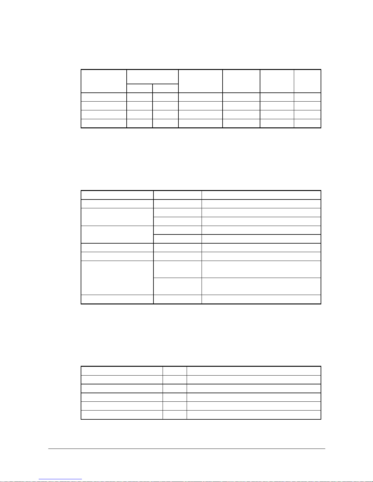
1.2. Available Models
Table 1.1
Memory Model
RAM FROM
Color touch panel
display
Digital camera Bluetooth
module
WLAN
module
IT-600M30 64 MB 128 MB Yes No Yes No
IT-600M30C 64 MB 128 MB Yes Yes Yes No
IT-600M30R 64 MB 128 MB Yes No Yes ETSI
IT-600M30CR 64 MB 128 MB Yes Yes Yes ETSI
1.3. Options
The table 1.2 shows the dedicated options available for the IT-600 series.
Table 1.2
Product Model Description
Cradle HA-D60IO USB Cradle (with Host/Client)
HA-D20BAT Lithium-ion battery pack (1,850 mAH) Battery pack
HA-D21LBAT Large-capacity lithium-ion battery pack (3,700 mAH)
HA-D30CHG Cradle-type Charger Battery charger
HA-D32DCHG Dual Battery Charger
Laser Redirection Attachment HA-D50BN Change the laser emission to downward at 60 degree.
CF Card Extension Unit HA-D94CFU For CF memory card on the back of IT-600
AD-S42120AE For HA-D60IO and HA-D32DCHG. Input from 100VAC
to 240VAC
AC adaptor
AD-S15050AE For HA-D30CHG. Input 100 to 240VAC (with US power
cord)
Cable DT-380USB USB cable for cradle, cable length 2.0 m
1.4. Accessories
The following accessories are accompanied in each individual carton box of IT-600 series.
Table 1.3
Name Q’ty Remark
User’s guide 1 In English and Chinese (in simplified Chinese characters)
Stylus 1
Large-capacity battery pack cover 1 Required when HA-D21LBAT is installed.
Neck strap 1
Touch screen protective sheet 1
7
Page 8

1.5. External Views
1.5.1. IT-600
17
10
1234
16
22
20
23
25
26
24
21
14
22
5
6
7
8,9
12
13
10
11
19
15
18
17
10
1234
16
22
20
23
25
26
24
21
14
22
5
6
7
8,9
12
13
10
11
19
15
18
Fig 1.1
See Table 1.4 for the descriptions for each referenced part on the Handheld Terminal.
8
Page 9

Table 1.4 Names of parts
No. Name Description
1 Buzzer Sounds a buzzer.
Orange : Charging the battery pack.
Green : Charging the battery pack complete.
2 Indicator 1
Red : Battery pack is abnormal or the surrounding temperature is out of the range.
3 Indicator 2 Flashes in blue when operating via Bluetooth or in orange when operating via WLAN.
Lights in green when reading a bar code successfully or in red when alarming
(programmable).
4 Power Key Turns the power on and off.
5 Touch Screen Displays text and operating instructions. Also used to operate the Handheld Terminal and
enter data using stylus provided.
6 Center Trigger
Key
Used to perform bar code reading. Can be assigned an arbitrary function.
7 Execute Key Press when finishing entering numerical values or when moving to the next step.
8 Text Key Press when switching to the text input mode.
9 Fn Key Used to make various settings in combination with the numeric keys or when starting a
pre-registered application.
10 CLR Key Used to clear one letter to the left of the input key.
11 Numeric Keys Used to enter numbers or letters.
12 Microphone Used to input a sound including voice.
13 Speaker Alarms and voice messages are output here. Voice messages are not output from the
speaker when a headset is connected to the headset jack. (The sound of camera shutter is
always output from the speaker.)
14 Trigger R Key Used to perform bar code reading.
15 Trigger L Key Used to perform bar code reading.
16 Headset Jack A separately sold headset can be connected here.
17 Reader Port Emits a laser that reads bar codes.
18 IR Port Used for communication with another Handheld Terminal.
19 Power
Supply/Charge
Ter mi na ls
Used to supply power to the Handheld Terminal and to charge the battery pack from
Cradle and Cradle-type Charger.
20 Digital Camera Used to capture photographs, images.
21 LED Light Used to light up an object when capturing with the digital camera.
22 Strap Holes Used to attach the strap.
23 Extension Port Provided for future extension.
24 Reset Switch Used to reset the Handheld Terminal.
25 Battery Pack
Cover Lock
Switch
Used to lock the battery cover and to release.
26 Battery Pack
Cover
Used to cover the battery compartment that holds the battery inside.
9
Page 10
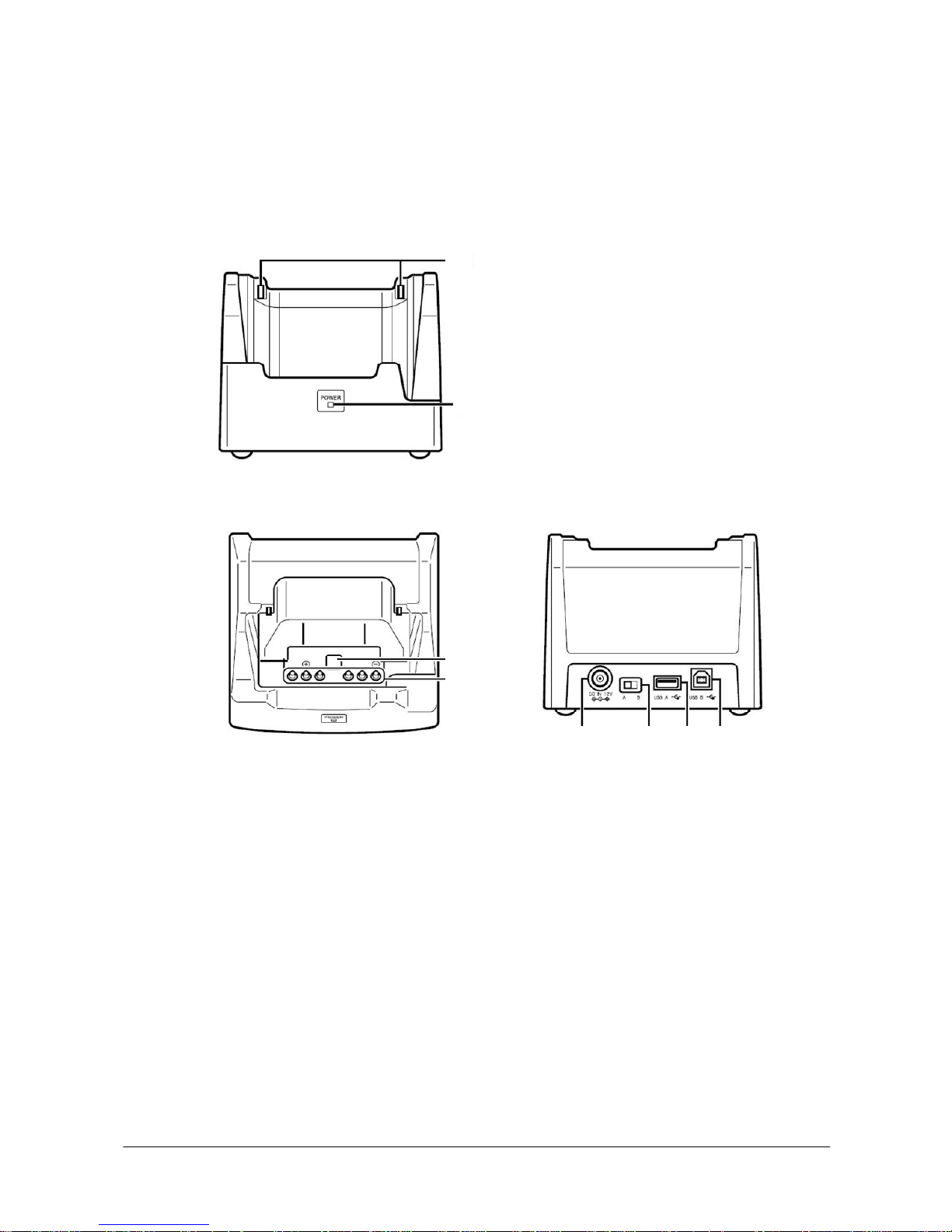
1.5.2. HA-D60IO
The following external views show the HA-D60IO (USB Cradle). Refer to Table 1.5 for each
referenced part on the HA-D60IO.
Views
Front
Top Rear
8
7
5
6
4 3 2 1
Front
Top Rear
8
7
5
6
4 3 2 1
Fig 1.2
10
Page 11
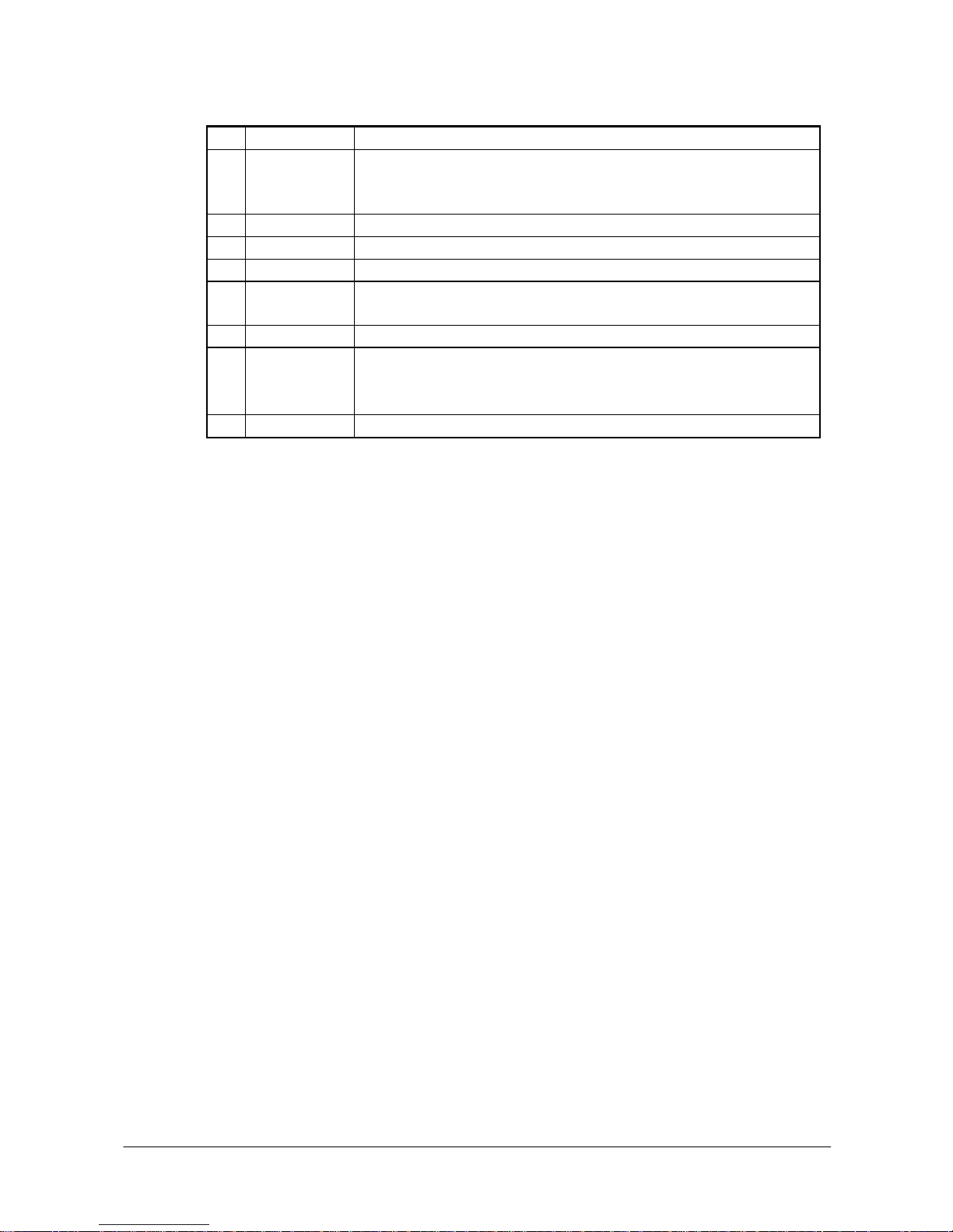
Table 1.5 Names of parts
No. Name Description
1 USB Client Port Used to transfer system data and file data (download, upload) by connecting the Cradle to
a PC using a USB cable (DT-380USB). A dedicated driver must be installed in the PC
before connecting the Cradle to the PC.
2 USB Host Port Used to connect a corresponding USB peripheral device.
3 Selector Switch Used to switch between the USB host port and USB client port.
4 AC Adaptor Jack Connect the dedicated AC adaptor here.
5 Terminal Detect
Switch
This switch detects when the Handheld Terminal is mounted correctly on the Cradle.
6 Power Contacts Power is supplied to the Handheld Terminal via these contacts.
This lamp indicates the power status and the mounting status of the Handheld Terminal.
Off : Handheld Terminal is mounted.
7 Power Indicator
Lamp
Green : Power on and the Handheld Terminal is mounted correctly.
8 Mount Hooks These hooks are used to stabilize the Handheld Terminal when mounting it on the cradle.
11
Page 12

1.5.3. HA-D32DCHG (Dual Battery Charger)
The following external views show the HA-D32DCHG (Dual Battery Charger). Refer to Table 1.6
for each referenced part on the HA-D32DCHG.
Views
4
2
3
1
3
Right Top Left
Bottom
4
2
3
1
3
Right Top Left
Bottom
Fig 1.3
Table 1.6 Names of parts
No. Name Description
These lamps indicate the charge status of each battery pack.
Off : Not charging
Red : Charging
Red Flashing : Battery pack problem
1 Charge indicator lamps
Green : Charging complete
2 AC adaptor jack Used to connect the dedicated AC adaptor here.
3 Dual battery charger
connection port
Used to connect another Dual Battery Charger at side.
4 Connection bracket
attachment holes
The connection bracket attaches here when you connect another Dual Battery
Charger.
12
Page 13

1.5.4. HA-D30CHG (Cradle-type Charger)
The following external views show the HA-D30CHG (Cradle-type Charger). Refer to Table 1.7 for
each referenced part on the HA-D30CHG.
Views
Front
Top Rear
5
4
3
2
1
Front
Top Rear
5
4
3
2
1
Fig 1.4
Table 1.7 Names of parts
No. Name Description
1 AC Adaptor
Jack
Connect the AC adaptor here.
2 Terminal Detect
Switch
This switch detects when the Handheld Terminal is mounted correctly on the charger.
3 Power Contacts Power is supplied to the handheld Terminal via these contacts.
This lamp indicates the power status and the mounting status of the Handheld Terminal.
Off : Handheld Terminal is not mounted.
4 Power
Indicator Lamp
Green : Power is on and the handheld Terminal is mounted correctly.
5 Mount Hooks These hooks are used to stabilize the Handheld Terminal when mounting it on the charger.
13
Page 14

1.5.5. HA-D50BN (Laser Redirection Attachment)
View
Fig 1.5
14
Page 15

1.5.6. Device Configuration Diagram
Fig 1.6
15
Page 16

2. Hardware Specifications
2.1. IT-600
Table 2.1
Item Specification Remark
CPU, Memory
CPU Intel® PXA270 Application Processor Operating clock; max 520
MHz
RAM 64 MB
FROM 128 MB (user area; approx. 60 MB)
Scanner
Type Semi-conductor laser light
Wave Length 650±10 nm
Optical Output <1 mW
No. of scannings 100±20 times per second
Resolution 0.127 mm (minimum)
PCS 0.45 (minimum)
Approximately 40 to 300 mm Without HA-D50BN Readable distance
Approximately 0 to 200 mm With HA-D50BN
Max. 40 mm When the distance is at 40 mm.
Max. 250 mm When the distance is at 300
mm.
Readable width
Max. 60 mm (contact scanning) When HA-D50BN is attached.
Daylight for scanning 50,000 Lux or less
Readable 1D bar code
symbologies
UPC-A, UPC-E, EAN, NW7, Code39, ITF, MSI,
Industrial 2of5, Code93, Code128, IATA, EAN128,
RSS-14, RSS Limited, RSS Expanded
Vibrator Yes (for indications of scanning completion, VoIp
call-in)
Display
Display device 3.7-inch transflective TFT color LCD 65,536 colors
No. of dots 480 (h) x 640 (w)
Dot pitch 0.117 (h) x 0.117 (w) mm
Display font Scalable font
Backlight LED
Indicator
LED 1pc x LED (2 colors), 1pc x LED (3 colors) Left: battery charge status
Right: programmable
Continue.
16
Page 17

Input
Keyboard Numeric (Alphabet) keys, CLR key, Execute key,
Fn key, Text key, Cursor key
Control keys Power ON/OFF key, Reset switch
Trigger keys Trigger R key, Trigger L key, Center trigger key
Touch panel Yes
Infrared communication interface
Standard IrDA ver.1.3 compatible
Communication process Half duplex
Synchronization Start-stop, frame method
Baud rate (in bps) 9,600/19,200/38,400/57,600/115,200/4M
Comm. range 0 (contact) to 0.3m
WLAN
Standard IEEE 802.11b, IEEE802.11g compatible
Modulation DS: IEEE802.11b
DS/OFDM (*): IEEE802.11g
Frequency range IEEE802.11b: 2.400 to 2.4835 GHz
IEEE802.11g: 2.400 to 2.4835 GHz
Baud rate IEEE802.11b: 11 Mbps (maximum)
IEEE802.11g: 54 Mbps (maximum)
Comm. range IEEE802.11b: 50 m (indoor) to 150 m (outdoor)
IEEE802.11g: 50 m (indoor) to 150 m (outdoor)
Vary depending on the
environment
Number of channels 13 Three channels are available at
the same time.
Output power 10±1dBm
Other feature Roaming between Access-Points
Bluetooth
Standard Bluetooth® Specification Ver.1.2 Not operable concurrently with
WLAN operation.
Comm. range Approx. 3 m Vary depending on the
environment
Output power Max. 3 dBm ( PowerClass 2)
USB
Full speed (12 Mbps) Baud rate
Low speed (1.5 Mbps)
Host
Power to an
external
device
5V±5% (maximum 500 mA) See note on page 17.
Client Baud rate Full speed (12 Mbps)
Extension port Connector for HA-D94CFU or for HA-D51TG Not applicable to IT-600M30R,
M30CR.
Continue.
17
Page 18

SD card slot miniSD memory card In the battery compartment.
Layout
1234567
Ter mi na ls
for USB
cradle
Description See Table 2.2
Headset jack 4 poles in rounded shape
Speaker Monaural
Microphone Monaural
Digital camera
Number of pixels Approximately 1,000,000 pixels
Device 1/4.5-type CCD color
Aperture F3.5/F7.0 (2 steps switchover)
Focal distance f = 3.29 mm (fixed)
Image capture range 30 cm to ∞
LED light
Brightness 3300 mcd
Power
Operation Lithium-ion battery pack (HA-D20BAT or
HA-D21LBAT)
Memory backup Lithium battery (rechargeable) on board
Battery capacity HA-D20BAT 1,850 mAH
HA-D21LBAT 3,700 mAH
* ; Orthogonal frequency-division multiplexing (OFDM) is a transmission technique based upon the
idea of
frequency-division multiplexing (FDM).
Continue.
18
Page 19

IT-600M30/M30C IT-600M30R/M30CR Operating period
Approx. 11 hours (with
HA-D20BAT)*1
Approx. 22 hours (with
HA-D21LBAT)*1
Approx. 10 hours (with
HA-D20BAT)*2
Approx. 20 hours (with
HA-D21LBAT)*2
*1 based on the ratio of
“standby:calculation:scan” at
20:1:1 when the CPU speed
is set to auto power save
mode and the backlight is
turned off.
*2 based on the ratio of
“standby:scan:calculation:wir
eless” at 20:1:1:1 when the
CPU speed is set to auto
power save mode and the
backlight is turned off.
Memory back up period RAM : Approx. 10 minutes, Clock : Approx. 72
hours
Lithium battery pack is fully
charged.
At room temperature.
Battery pack charge
period
Approximately 4 hours for HA-D20BAT
Approximately 7 hours for HA-D21LBAT
The power on the terminal is
turned off.
At room temperature
The dedicated AC adaptor is
used to power the terminal
via battery charger or cradle.
Memory backup battery
charge period
Approximately 4 days Time period until when the
battery is fully charged.
Battery pack is being
installed.
At room temperature.
Memory backup battery
rated capacity
10 mAh
Power supply by cradle Yes
By battery pack (when
terminal’s power on )
Ye s
Method to charge
memory backup battery
By battery pack (when
terminal’s power off)
Ye s
19
Page 20

• Terminal layout and the description
Table 2.2
Terminal no. Signal Description Direction
1 V BUS Power from USB cradle OUT/IN (see note)
2 V CRADLE Power supply/Charge to terminal -
3 D + USB D + IN/OUT
4 NC -
5 USB_ID Switch-over between USB host and USB client IN
6 D - USB D - IN/OUT
7 GND GND -
Note:
When the selector switch on the HA-D60IO is set to “USB Host”, this terminal is used to output the
power ON/OFF control signal issued by the IT-600 to the cradle. Or, when it is set to “USB Client”,
the terminal is used to input the USB power (V BUS) from the cradle to the IT-600.
20
Page 21

2.2. HA-D60IO
Table 2.3
Item Specification Remark
Standard USB Ver.1.1 compatible
Baud rate Max. 12 Mbps (maximum)
USB connector B type
1 VBus
2 – Data (D -)
3 + Data (D+)
4 GND
USB
Connector
12341234
USB connector A type
1 VBus
2 – Data (D -)
3 + Data (D+)
4 GND
Input voltage DC 12V ±5%
Current consumption DC12V approx. 1.6A When supplying power and
transmitting data.
Plug EIAJ RC-5320A type 4 Center; +
Power from AC
adaptor
AC adaptor AD-S42120AE
Standard USB Ver. 1.1 compatible
Baud rate 12 Mbps (maximum)
1.5 Mbps (minimum)
USB host
Power to
external
device
5V±5% maximum 500 mA
Standard USB Ver. 1.1 compatible
Baud rate 12 Mbps (maximum)
Layout See Fig 2.1.
USB client
Description See Table 2.4
Output
voltage
DC5V±10%
Output
current
2,500 mA (maximum)
Output
current
Constant voltage method With current limitation
control
Power
Charge/Po
wer supply
terminals
Battery
charge
time
Approx. 4 hours (for HA-D20BAT)
Approx. 7 hours (for HA-D21LBAT)
21
Page 22

• Terminal layout
123 456123 456
Fig 2.1
• Terminal layout and the description
Table 2.4
Terminal no. Signal Description Direction
1 V BUS Power from USB cradle OUT/IN (see note)
2 V CRADLE Power supply/Charge to IT-600 -
3 D + USB D + IN/OUT
4 USB_ID Switch-over between USB host and USB client IN
5 D - USB D - IN/OUT
6 GND GND -
Note:
When the selector switch on the HA-D60IO is set to “USB Host”, this terminal is used to receive the
power ON/OFF control signal issued by the IT-600. Or, when it is set to “USB Client”, the terminal
is used to output the USB power (V BUS) to the IT-600.
2.3. HA-D32DCHG
Table 2.5
Item Specification Remark
Charge method Constant voltage constant current
Approx. 2 hours ( for 1 pc x HA-D20BAT)
Approx. 4 hours (for 1 pc x HA-D21LBAT)
Approx. 3.5 hours (for 2 pcs x HA-D20BAT)
Battery charge
Charge period
Approx. 7 hours (for 2 pcs x HA-D21LBAT)
At room
temperature
Required power supply AD-S42120AE (dedicated AC adaptor)
Approx. 0.8 A (with single HA-D32DCHG) Consumption current
Approx. 2.4 A (with three HA-D32DCHGs
connected.)
Operating temperature Approx. 0 to 40 ºC
Operating humidity 30 to 80 %RH
No. of the chargers to be connected 3 pcs x HA-D32DCHG (maximum)
22
Page 23

2.4. HA-D30CHG
Table 2.6
Item Specification Remark
Input voltage DC 5V±5%
Consumption
current
DC5V approx. 2.5 A
Plug EIAJ RC-5320A type 3 Center pin; +
Input from AC adaptor
AC adaptor AD-S15050A Dedicated AC adaptor
Ter m inal l ayou t
Power supply
GND
Output voltage DC5V±10%
Output current 2500 mA (maximum)
Charge method Constant voltage With current limitation
control
Approx. 4 hours (for HA-D20BAT)
Power supply/Charge
Charge period
Approx. 7 hours (for HA-D21LBAT)
2.5. HA-D20BAT/HA-D21LBAT
HA-D20BAT (Battery Pack)
Table 2.7
Item Specification Remark
Nominal capacity 1850 mAh
Nominal voltage 3.7 V
Dimensions Approx. 52.5(W) x 40(L) x 13.5(H) mm
Weight Approx. 46g
Accessory Soft case
HA-D21LBAT (Large-capacity Battery Pack)
Table 2.8
Item Specification Remark
Nominal capacity 3700 mAh
Nominal voltage 3.7 V
Dimensions Approx. 52.5 (W) x 40 (L) x 25 (H) mm
Weight Approx. 86g
Accessory Soft case
23
Page 24

2.6. HA-D50BN
Table 2.9
Item Specification Remark
Angle of laser beam emission 60 º downward
Dimensions Approx. 91.2 (W) x 63.15 (L) x 45.9 (H) mm
Weight Approx. 60g
24
Page 25

3. Product Identification And Reference Numbers
On the back of the IT-600 and the options, there is a bar code and numbers printed on label as shown
in Fig 3.1. This bar code is represented by 15 digits of Code128 symbology and by alphanumeric
characters beneath the bar code. The numbers from 1 to 9 in the figure represent identification and
references of each terminal. The numbers from 10 to 15 represent a manufacturing reference which
is reserved by the manufacturer. See the figure below for each meaning.
1234 5 6 7 8 9 101112131415
Production month of the year (1 to 9, A,B,C)
Production year (last digit only. Ex. 1 represents the year 2001.)
Model number (two digits in alphanumeric)
A8: IT-600M30
A9: IT-600M30C
AA: IT-600M30R
AB: IT-600M30CR
AD: HA-D30CHG
AC: HA-D60IO
Serial number of the terminal
in 5 digits
Manufacturin g refere nces
(reserved by the manufacturer)
Check digit
Fig 3.1
25
Page 26

4. Quality References
This chapter will describe about references of the IT-600 and its dedicated options concerned with
environmental performance, compliance, mechanical and electric durability, etc.
4.1. Environmental Performances
4.1.1. IT-600
Table 4.1
Item Specification Condition
Temperature
Operation -10 ºC to 50 ºC 0 to 40 ºC for charging
battery pack
Non-operation -20 ºC to 60 ºC
Humidity
Operation 10 % to 80 %RH
Non-operation 5 % to 90 %RH
No condensation
Storage
Temperature -20 ºC to 60 ºC
Humidity 5 % to 90 %RH No condensation.
Dust and water-splash proof
IP54 level Compliant with IEC60529
standard
4.1.2. HA-D60IO
Table 4.2
Item Specification Condition
Temperature
Operation 0 ºC to 40 ºC
Non-operation -20 ºC to 60 ºC
Humidity
Operation 30 % to 80 %RH
Non-operation 10 % to 90 %RH
No condensation
Storage in carton box
Temperature -20 ºC to 60 ºC
Humidity 10 % to 90 %RH No condensation
Dust and water-splash proof
Not applicable
26
Page 27

4.1.3. HA-D32DCHG
Table 4.3
Item Specification Condition
Temperature
Operation 0 ºC to 40 ºC
Non-operation -20 ºC to 60 ºC
Humidity
Operation 30 % to 80 %RH
Non-operation 10 % to 90 %RH
No condensation
Storage in carton box
Temperature -20 ºC to 60 ºC
Humidity 10 % to 90 %RH No condensation
Dust and water-splash proof
Not applicable
4.1.4. HA-D30CHG
Table 4.4
Item Specification Condition
Temperature
Operation 0 ºC to 40 ºC
Non-operation -20 ºC to 60 ºC
Humidity
Operation 30 % to 80 %RH
Non-operation 10 % to 90 %RH
No condensation
Storage in carton box
Temperature -20 ºC to 60 ºC
Humidity 10 % to 90 %RH No condensation
Dust and water-splash proof
Not applicable
27
Page 28

4.1.5. HA-D50BN
Table 4.5
Item Specification Condition
Temperature
Operation -10 ºC to 50 ºC
Non-operation -20 ºC to 60 ºC
Humidity
Operation 10 % to 80 %RH
Non-operation 5 % to 90 %RH
No condensation
Storage in carton box
Temperature -20 ºC to 60 ºC
Humidity 90 %RH or less No condensation
Dust and water-splash proof
Not applicable
28
Page 29

4.2. Electrical Performances
4.2.1. IT-600
Table 4.6
Item Specification Remark
Power consumption
DC1.8A
- IT-600M30R
DC1.9A
- IT-600M30, IT-600M30CR
DC2.0A
- IT-600M30C
Anti-static strength
Malfunction
±4 KV
Destruction
±12 KV
- 150 pF, 330ohm
4.2.2. HA-D60IO
Table 4.7
Item Specification Remark
Input voltage
DC12V±5%
Anti-static strength
In contact
±6 KV
In air
±8 KV
- 150 pF, 330 ohm
Power interruption 10 millisec. or less
Line noise strength
Malfunction 1,000 V
- Pulse frequency: 5KHz
- Burst cycle: 300 millisec.
- Number of pulses: 75
- Burst interval: 15 millisec.
29
Page 30

4.2.3. HA-D32DCHG
Table 4.8
Item Specification Remark
Consumption current
Approx. 0.03 A
- While the battery pack is not being installed.
Approx. 0.8 A
- While the battery pack is installed and it is being
charged.
Input voltage
DC12V±5%
Anti-static strength
In contact
±6 KV
In air
±8 KV
- 150 pF, 330 ohm
Line noise strength
Malfunction 1,000 V
- Pulse frequency: 5KHz
- Burst cycle: 300 millisec.
- Number of pulses: 75
- Burst interval: 15 millisec.
4.2.4. HA-D30CHG
Table 4.9
Item Specification Remark
Input voltage
DC5V±5%
Anti-static strength
In contact
±6 KV
In air
±8 KV
- 150 pF, 330 ohm
Power interruption 10 millisec. or less
Line noise strength
Malfunction 1,000 V
- Pulse frequency: 5 KHz
- Burst cycle: 300 millisec.
- Number of pulses: 75
- Burst interval: 15 millisec.
30
Page 31

4.3. Mechanical Performances
4.3.1. IT-600
Table 4.10
Item Specification Condition
Resistance to drop impact
(height)
120 cm
- Onto concrete floor.
- One time on each of the 6 sides and 4
corners.
Resistance to impact
70 cm (in individual carton box) Height of drop
70 cm (in master carton)
- 1 cycle on each of the 6 sides and 1
corner.
Resistance to vibration 1.5 G
- 10 to 55 Hz
- In X,Y, and Z directions
- Reciprocally for 30 minutes
4.3.2. HA-D60IO
Table 4.11
Item Specification Condition
Resistance to vibration 1.5 G or less
- 10 to 55 Hz
- In X,Y, and Z directions
- Reciprocally for 30 minutes
- While the power is turned on and IT-600
is not being mounted.
Resistance to vibration
(in carton box)
1.5 G or less
- 10 to 55 Hz
- In X,Y, and Z directions
- Reciprocally for 15 minutes
Resistance to drop impact
In bare condition 70 cm
In individual carton 70 cm or less
In master carton 50 cm or less
- 1 cycle on each of the 6 sides
- 6 faces, 1 corner and 3 edges
- Onto P tile floor.
31
Page 32

4.3.3. HA-D32DCHG
Table 4.12
Item Specification Condition
Resistance to vibration 1.5 G or less
- 10 to 55 Hz
- In X,Y, and Z directions
- Reciprocally for 15 minutes
- While the power is being turned off.
Resistance to vibration
(in carton box)
1.5 G or less
- 10 to 55 Hz
- In X,Y, and Z directions
- Reciprocally for 15 minutes
Resistance to impact
In bare condition 70 cm
In individual carton 70 cm or less
In master carton 60 cm or less
- 1 cycle on each of the 6 sides
- 6 faces, 1 corner and 3 edges
- On to concrete floor.
4.3.4. HA-D30CHG
Table 4.13
Item Specification Condition
Resistance to vibration 1.5 G or less
- 10 to 55 Hz
- In X,Y, and Z directions
- Reciprocally for 15 minutes
- While the power is turned on and
IT-600 is not being mounted.
Resistance to vibration
(in carton box)
1.5 G or less
- 10 to 55 Hz
- In X,Y, and Z directions
- Reciprocally for 15 minutes
Resistance to impact
In bare condition 70 cm
In individual carton 70 cm or less
In master carton 50 cm or less
- 1 cycle on each of the 6 sides
- 6 faces, 1 corner and 3 edges
- On to concrete floor.
32
Page 33

4.3.5. HA-D50BN
Table 4.14
Item Specification Condition
Resistance to vibration 1.5 G or less
- 10 to 55 Hz
- In X,Y, and Z directions
- Reciprocally for 15 minutes
- With HA-D50BN being attached on
IT-600.
Resistance to impact
In bare condition 120 cm
- 1 cycle on each of the 6 sides
- 6 faces, 1 corner and 3 edges
- On to concrete floor.
- With HA-D50BN being attached on
IT-600.
In individual carton 70 cm or less
In master carton 70 cm or less
- 1 cycle on each of the 6 sides
- 6 faces, 1 corner and 3 edges
- On to concrete floor.
33
Page 34

4.4. Reliability
4.4.1. IT-600
Table 4.15
Item Specification Condition
Service life
Backlight 15,000 hours
LCD 50,000 hours
Touch panel key input 800,000 times
- With 8.60º rubber with load of 250 g applied
Writing on touch panel 100,000 Katakana
characters
- With 0.8R polyacetar stylus with load of 250 g
applied
Discharge/charge cycle longevity
of battery pack
500 times
- Standard /Large-capacity battery
- 50% or more of the initial capacity
Battery pack storage period
(recommended)
One year or less
- In the range of temperature between -25 ºC and
30 ºC
- At 80% charge level
20,000 times
- Memory backup for a period of 10 minutes
Discharge/charge cycle longevity
of memory backup battery
40 times
- Memory backup until the cut-off voltage level
Plug in/unplug the
connector
miniSD
card
5,000 times
Digital camera 7,250 hours
LED light 1,000 hours
- Until when the brightness becomes 50%
Vibrator 300,000 cycles
- One cycle; 0.5s ON, 0.5s OFF
Reset switch 1,000 times
Trigger keys 1,000,000 times
Key input
durability
Keys (except the
Trigger keys)
500,000 times
Battery pack 5,000 times
On Cradle-type
charger
10,000 times
Mounting/r
emoving
durability
On USB cradle 10,000 times
MTBF
Electronic parts 45,381 hours
- Main PCB
34
Page 35

4.4.2. HA-D60IO
Table 4.16
Item Specification Condition
MTBF for electronic parts 20,000 hours
USB client port’s connector 500 times Installing and removing
USB host port’s connector 500 times
Mounting IT-600 and
removing
45,000 times
Switching Selector switch (USB Host or
USB Client)
500 times One reciprocal switching as
one time
Installing AC adaptor to and
removing from
AC adaptor jack 1,500 times
4.4.3. HA-D32DCHG
Table 4.17
Item Specification Condition
MTBF for electronic parts 50,000 hours
Mounting a battery pack and removing 5,000 times
Connecting to the joint connector and removing from 250 times
Installing AC adaptor to and removing from AC adaptor jack 1,500 times
4.4.4. HA-D30CHG
Table 4.18
Item Specification Condition
MTBF for electronic parts 20,000 hours
Mounting IT-600 on and removing from 45,000 times
Connecting to the joint connector and removing from 250 times
Installing AC adaptor to and removing from AC adaptor jack 1,500 times
4.4.5. HA-D50BN
Table 4.19
Item Specification Condition
Attaching HA-D50BN on IT-600 and removing from 2,000 times
35
Page 36

4.5. Compliance
4.5.1. IT-600
Table 4.20
Model EMC
EN55022:
1998
EMI
EN55024:
1998
Safety
EN60950
WLAN Type
Approval
EN 300.328-2
EN 301.489-17
EN50371
Bluetooth
Ty pe
Approval
Laser
EN60825-1:1996
(IEC60825-1:1997
Class 2)
IT-600M30 Yes Yes Yes No Yes Yes
IT-600M30C Yes Yes Yes No Yes Yes
IT-600M30R See note See note Yes Yes Yes Yes
IT-600M30CR See note See note Yes Yes Yes Yes
Note:
IT-600M30R and IT-600M30CR are compliant with the respective criteria set on the EN55022 and
EN55024 standards. The WLAN type approval requires both the models to meet the EN55022 and
EN55024 standards.
4.5.2. HA-D60IO
Table 4.21
Model EMC
EN55022:1998
EMI
EN55024:1998
EN61000-3
HA-D60IO Yes Yes Yes
4.5.3. HA-D32DCHG
Table 4.22
Model EMC
EN55022:1998
EMI
EN55024:1998
HA-D32DCHG Yes Yes
4.5.4. HA-D30CHG
Table 4.23
Model EMC
EN55022:1998
EMI
EN55024:1998
EN61000-3
HA-D30CHG Yes Yes Yes
36
 Loading...