

Page 1

IT-2000D
(DOS version)
Technical Reference
Manual
(Version 1.00 )
April 1998
Casio Computer Co., Ltd.
Copyright ©1998. All rights reserved.
Page 2

Table of Contents
Chapter1
Chapter2
Chapter3
Preface
Overview
1.1
1.1.1
1.1.2
1.1.3
1.1.4
1.1.5
1.2
1.2.1
1.2.2
1.3
Feature of System
Development Concept
Hardware
Software
Basic Specifications
Model Name 8
System Configuration
Hardware Block Diagram
Supported Software
Precautions
Basic Software
2.1
2.1.1
2.1.2
2.1.3
2.2
2.2.1
2.2.2
2.2.3
2.2.4
2.2.5
2.2.6
2.3
2.3.1
2.3.2
2.3.3
2.3.4
2.3.5
2.3.6
2.3.7
2.3.8
2.3.9
2.3.10
2.3.11
2.3.12
Overview
Software Configuration
Memory Map
Drive Configuration
Basic System Operation
Overview
Power ON Process
Power OFF Process
Battery Voltage Monitoring Process
Low Consumption Current Process
How to Replace or Recharge Batteries
Supported Devices 39
Display Unit 39
EL Backlight
Touch Panel
Disk
Serial Communication
PC Card
Clock Timer 49
Buzzer 50
Barcode Reader
Infrared Communication (Ir)
Keys
Sensors
System Menu
3.1
3.2
3.3
3.4
3.5
3.6
3.7
3.8
3.9
3.10 YMODEM Utility 64
Overview
Basic Operation
List of Functions
Key Click Sound Setup
Buzzer Volume Setup
Contrast Adjustment 59
Auto Backlight Setup
Auto Power OFF Setup
Touch Panel Calibration
5
6
6
6
6
6
7
9
9
10
12
15
15
15
16
17
19
19
21
25
28
33
37
41
42
43
45
47
51
52
53
54
55
55
56
56
57
58
60
61
62
2
Page 3

3.11 FLINK Command 68
3.12 System Date/Time Setup 71
3.13 Command Prompt 72
3.14 RAM Disk Size Change 73
3.15 Disk Format 75
3.16 System Initialization 77
3.17 Password Entry 78
Chapter4 MS-DOS 79
4.1 Overview 79
4.2 How to Write CONFIG.SYS and AUTOEXEC.BAT 81
4.3 Card Boot 84
Chapter5 Keyboard Controller 87
5.1 Overview 87
5.2 Keyboard Control 88
5.3 Touch Panel Control 90
5.4 Sensor Control 91
5.5 Backlight Control 92
Chapter6 Drivers 95
6.1 Overview 95
6.2 System Driver 96
6.2.1 Function 96
6.2.2 Startup Method 96
6.3 Clock Control Driver 97
6.3.1 Function 97
6.3.2 Startup Method 98
6.4 Keypad Driver/Hardware Window Manager 99
6.4.1 Function 99
6.4.2 Startup Method 100
6.5 PenMouse Driver 101
6.5.1 Overview 101
Startup Method 102
Functions 102
Application Development 110
Overview 110
Notes on Developing Application 111
Development Environment 112
Development Environment 112
Application Development Library 112
Simulation Driver 113
Program Development Procedure 114
Creation of Execution File 115
Debugging Through Simulation 117
Operation Check on IT-2000 (Using COM2KEY/XY) 119
Installation of Application Program 120
Simulation Driver 122
System Driver Simulator (SYSDRVP.COM) 123
Hardware Window Manager Simulator (HWWMANP.COM)
Keypad Driver Simulator (KEYPADP.COM) 126
Library 130
Overview 130
System Library 131
Keypad Library 153
OBR Library 170
DT-9650BCR 172
DT-9656BCR 181
125
Chapter
6.5.2
6.5.3
7
7.1
7.2
7.3
7.3.1
7.3.2
7.3.3
7.4
7.4.1
7.4.2
7.4.3
7.4.4
7.5
7.5.1
7.5.2
7.5.3
7.6
7.6.1
7.6.2
7.6.3
7.6.4
3
Page 4

Chapter8 Utility 190
8.1 Overview 190
8.2 Calculator Utility 191
8.3 Clock Utility 193
8.4 Calendar Utility 195
8.5 FLINK Utility 196
8.5.1 Communication Parameter Setup Command 197
8.5.2 File Transmission (/S) 199
8.5.3 File Reception (/R) 201
8.5.4 File Append (/A) 203
8.5.5 File Deletion (/D) 204
8.5.6 File Move/Rename (/N) 205
8.5.7 Idle Start 206
8.6 XY Utility 209
8.7 Remaining Battery Voltage Display Utility 214
8.8 Reverse Video Utility 216
8.9 COM2Key Utility 217
APPENDIXA TFORMAT.EXE 218
APPENDIXB PC Card Driver 219
APPENDIXC Acquisition of Suspend/Resume Event and
Power Status
222
4
Page 5

Preface
The IT-2000 Technical Reference Manual (hereinafter referred to as this document) is provided to
assist the user in developing programs to run on the Casio IT-2000 (hereinafter referred to as this
terminal or IT-2000 or HT in this manual). Microsoft C/C++ Ver.7.0 or later, and the manuals
supplied with it, is required to develop programs for this terminal.
Read Chapter 1 of this manual in its entirety to understand the features of this terminal.
Important notices to user
The information contained in this document may be modified without a prior notice.
Casio Computer Co., Ltd. shall not be liable for any outcome that result from the use of this
document and the terminal.
Copyright notice
The contents of this document are protected by the Copyright Law of Japan.
This document may not be reproduced or transferred in part or in whole, in any form without
permission from Casio Computer Co., Ltd.
Copyright © Casio Computer Co., Ltd. All rights reserved.
About MS-DOS 6.22
The MS-DOS copyright is the proprietary of Microsoft and is protected by the United States
Copyright Law and International Treaty provisions.
The MS-DOS software shall not be modified, reverse-engineered, decompiled, or disassembled. Any
form of reproduction is also absolutely prohibited.
About trademarks
AT and IBM PC/AT are registered trademarks of International Business Machines
Corporation in the United States.
MS, MS-DOS, Microsoft C/C++, Visual C ++, Visual Basic, and MS-Windows are registered
trademarks of Microsoft Corporation in the United States.
5
Page 6

1. Overview
1.1 Features of System
1.1.1 Development Concept
The IT-2000 is a data collection terminal for business use. After years of refinement Casio
Computer Co., Ltd. has developed its hand-held type terminals so that they yield high speed and
a high functionality in comparison to general personal computers. This allows improved efficiency
in software development.
It has adopted the IBM PC/AT architecture and incorporated an IBM PC/AT compatible BIOS. It
uses MS-DOS Ver. 6.22 for its OS. This has drastically improved the software development
environment and compatibility to IBM PC/AT family applications.
The adoption of a power-saving type 32-bit CPU, the Intel 80486GX, allows the terminal to operate
continuously for eight hours (when the backlight is off).
1.1.2 Hardware
Global IBM PC/AT architecture standard is adopted.
Compact design: 85 (W) x 196 (L) x 30 (H) mm, 430 g (approx.)
Uses a 32-bit CPU (Intel 80486 GX) for 25 MHz high-speed operation.
High-resolution (192 x 384 pixels), large-size liquid crystal touch panel.
Supports various interfaces, including RS-232C (8-pin, 14-pin), IR, and PC card.
High environmental adaptability: Operation temperature at between -5 and 50, water splash
proof capability conforms to the IPXII standard, etc.
Uses a small-size, large capacity lithium-ion battery pack as the main battery.
Incorporates a large capacity flash ROM drive as the user drive.
1.1.3 Software
MS-DOS Ver. 6.22 as the operating system.
IBM PC/AT-compatible BIOS makes it easy to develop user application programs.
Uses APM 1.1, for advanced low-power consumption capability.
6
Page 7

PC card slot conforms to PCMCIA Release 2.1 supporting various PC cards.
Implements IrDA 1.1 protocol for high-speed infrared communication.
System menu makes it easy to maintain the IT-2000 and install user application programs.
Provides various development support tools including C-language libraries and communication
utilities for developing business application programs.
1.1.4 Basic Specifications
IT-2000
Architecture
IBM PC/AT architecture
External dimensions and weight
Dimensions : 85 (W) x 196 (L) x 30 (H) mm
Weight : 430 g (approx.)
CPU
Intel 80486GX(32-bit)
Memory
DRAM : 4 MB
F-ROM : 0/4/8/12/16/24 MB (depending on the model)
MASK ROM : 8 MB, Windows file (IT-2000W only)
BIOS ROM : 1 MB (BIOS section: 256 KB, Drive C image: 768 KB)
Display and input
LCD panel : 192 x 384 dots (FSTN semi-transparent LCD),
with EL backlight
Touch panel : Analog, 192 x 384 dots
Interface
8-pin : RS-232C
14-pin : RS-232C
IrDA : Standards 1.0/1.1
PC Card : PCMCIA Release 2.1
Power supply
Main battery : Lithium-ion battery pack (x 1)
Sub-battery : Lithium-vanadium battery (x 1), lithium battery (x 1)
Operating hours : 8 hours (if backlight off)
Backup period : 2 weeks
Environment conditions
Temperature
Reliability
Water-splash proof : Conforms to IPXII standard
Software
BIOS : IBM PC/AT compatible
OS : MS-DOS Version 6.22
F-ROM : NAND flash file system
Basic functions : Suspend/Resume, Auto Power OFF, Auto Backlight
: Operation -5 to 50
: Storage -10 to 55
OFF, Auto Backlight ON/OFF with light intensity
detection, Auto Power ON with timer/ring
signal/detection of mounted I/O Box
7
Page 8

1.1.5 Model Name
The following IT-2000s of MS-DOS version will be available. For price of each model, please
consult with your local Casio representative.
Model RAM Flash ROM Remark
IT-2000D10 4 Mbytes IT-2000D20 4 Mbytes 4 Mbytes
IT-2000D30 4 Mbytes 8 Mbytes
IT-2000D60 4 Mbytes 24 Mbytes
8
Page 9
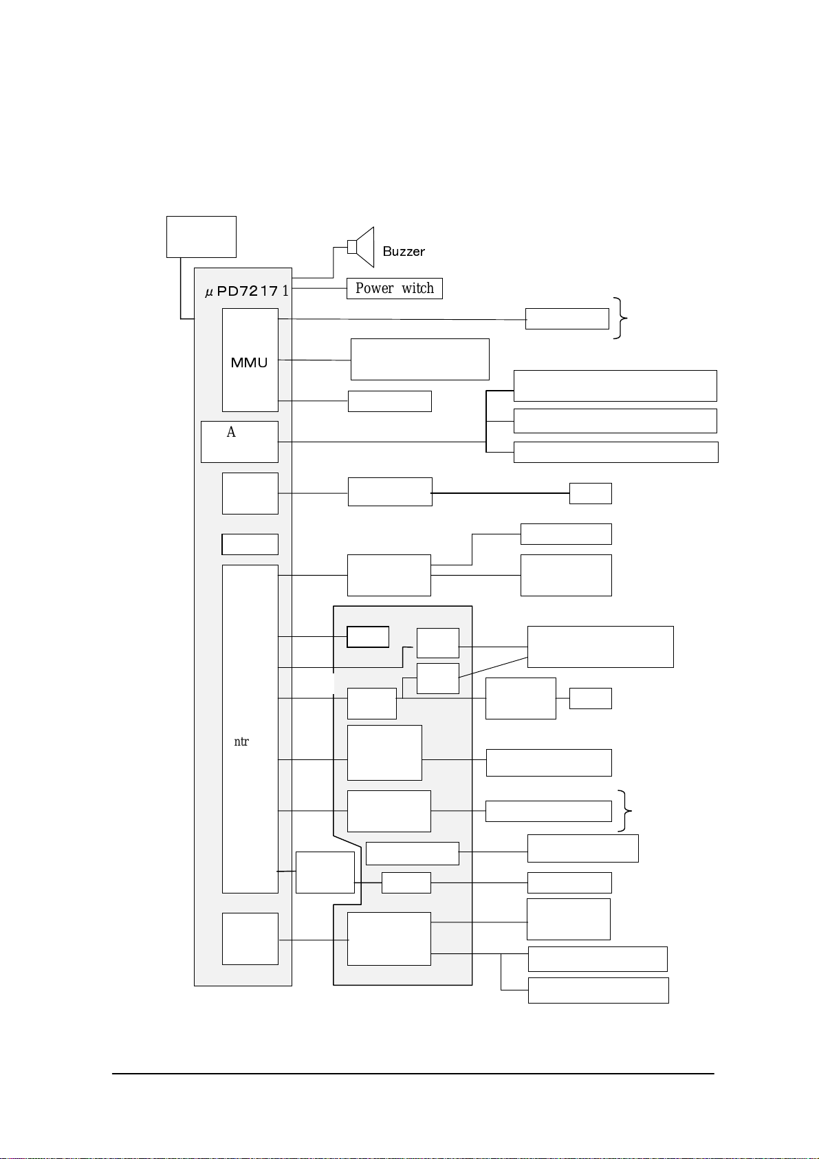
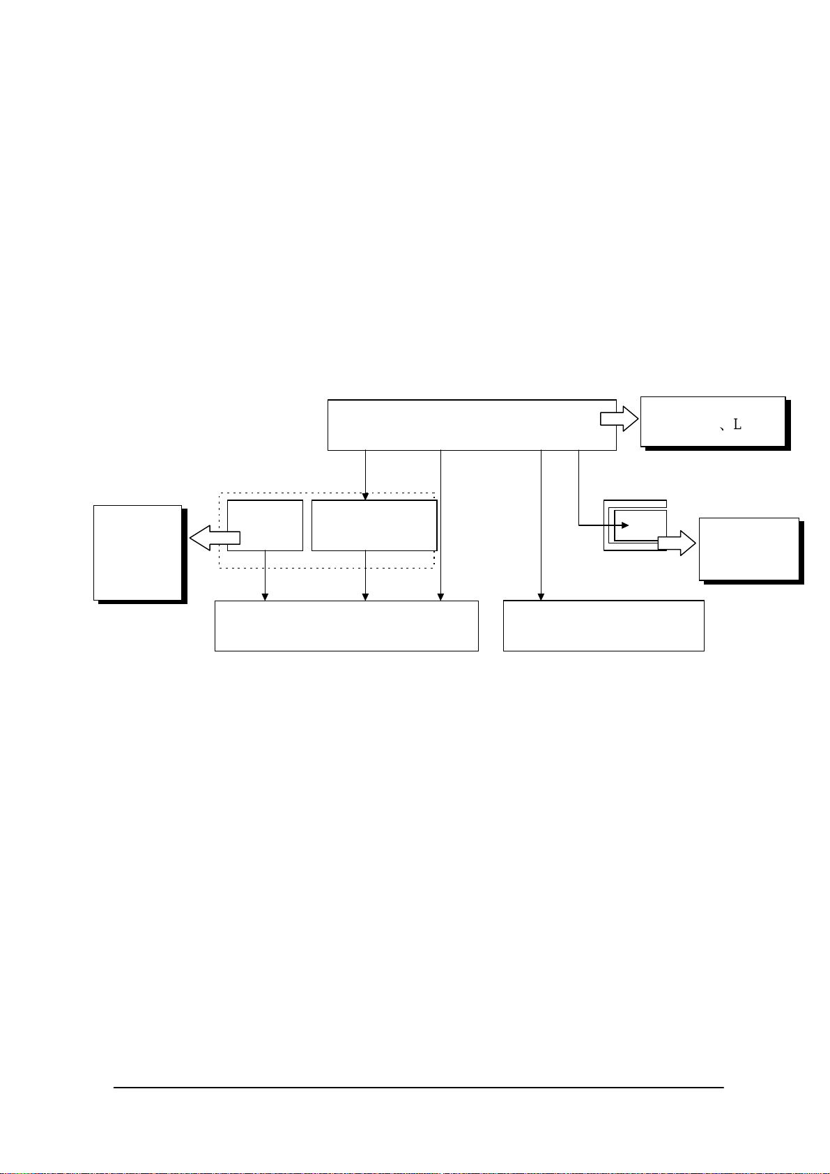
1.2 System Configuration
1.2.1 Hardware Block Diagram
CPU
i486GX
A/D
converter
UART/
SIR
RTC
BUS
Controller
1
COM 2
COM 1
VGA
controlle
Power switch
FLASH ROM
DRAM
Buffer
Keyboard
controller
ASIC
RTC
16550
PC card
controller
NAND
interface
BL controller
r
(DINOR)
IrDA
1.1
IrDA
1.0
For IT-2000W
MASK ROM
only
Battery voltage monitoring sensor
Temperature sensor
Illumination sensor
8-pin
Key
Analog touch
panel
IrDA
Driver/Receiver
RS-232C
driver
14-pin
PC card slot
IT-2000D20
NAND FLASH
IT-2000D30
IT-2000D60
EL Backlight
LCDLCTC
PMU
PMU
Lithium-ion
battery
Primary sub-battery
Secondary sub-battery
9
Page 10

1.2.2 Supported Software
The software used with this terminal can be divided into two categories: the system software that
includes the BIOS, OS, and device drivers and the user software such as the development tools.
The system software is stored on the DINOR FLASH ROM (1 MB), and the user software is
supported from the SDK CD-ROM (version 4.0) supplied by Casio at free of charge. The following
paragraphs describe the software.
BIOS
The BIOS program is stored in the DINOR FLASH ROM. 256 KB of DINOR FLASH ROM is
allocated specifically as the BIOS storage area.
The BIOS of this terminal consists of the standard PC/AT BIOS section, PEN BIOS for supporting
the touch panel, extension BIOS for supporting devices inherent to this terminal, and APM BIOS for
attain the low-power consumption capability.
MS-DOS Main Part
The main part of the MS-DOS Ver. 6.22 is stored in drive (C:).
In drive (C:) 768 KB of memory area in the DINOR FLASH ROM (1 MB) is allocated. Because of
the capacity limitation, only the essential MS-DOS files are stored in drive (C:). Therefore, if using
an MS-DOS file that is not included in the main part, copy it from the Backup CD-ROM (title on
CD-ROM: MS-DOS version 6.22 Software) to the F-ROM drive (D:) or RAM disk (A:).
For information about each MS-DOS file refer to an MS-DOS manual, commonly available at book
stores.
Device Drivers and System Files
These files must be loaded via CONFIG.SYS or AUTOEXEC.BAT at boot-up. These files are all
stored in drive (C:).
File name Storage location Description
SYSDRV.SYS Basic drive (C:) System driver
TIME.SYS Basic drive (C:) Clock control driver
CS.EXE, etc. Basic drive (C:) PC card driver
CASIOAPM.COM Basic drive (C: ) Touch-panel enabler
ENDATA.COM Basic drive (C:) ATA card-related data
CKRAMDSK.EXE
CKRAMDSK.DAT
CALIB.EXE Basic drive (C:) Calibration
SYSMENU.EXE Basic drive (C:) System Menu
HWWMAN.EXE Basic drive (C:) Hardware window manager
KEYPAD.EXE
KEYPAD.DAT
Basic drive (C:)
Basic drive (C:)
Basic drive (C:) Keypad
RAM disk checker
10
Page 11

TFORMAT.EXE Basic drive (C:) F-ROM drive formatter
Utilities
For information about the utilities refer to Chapter 8 "Utility".
File name Storage location Description
CAL.EXE SDK Calendar utility
CALC.EXE SDK Calculator utility
CLOCK.EXE SDK Clock utility
CHKBATT.EXE SDK Power status indication utility
XY.EXE Basic drive (C:) XY utility
FLINK.EXE Basic drive (C:) FLINK utility
LCDREV.EXE SDK Reverse video utility
Development Tool Libraries
File name Storage location Description
SLIBSYSD.LIB
MLIBSYSD.LIB
LLIBSYSD.LIB
SYSLIB.H
SLIBPAD.LIB
MLIBPAD.LIB
LLIBPAD.LIB
PADLIB.H
KEYPADP.EXE
HWWMANP.EXE
SLIBOBRD.LIB
MLIBOBRD.LIB
LLIBOBRD.LIB
OBRLIB.H
COM2KEY.EXE Basic drive (C:) COM < -- > Key for DEBUG
PENMOUSE.COM SDK Pen mouse driver
PMON.COM
PMOFF.COM
SDK System library
SDK Keypad library
SDK Keypad for PC simulation
SDK OBR library
Drive (C:) Switching DOZE mode on/off
11
Page 12

1.3 Precautions
If reading the internal clock with INT21h the significant data should include and be limited to
the seconds digits. On this terminal the time is read directly from the RTC so that the correct
time can be attained at any moment, even during extended continuous use. As a result the 1/100
of a second digit is ignored. (refer to Chapter 6.3 “Clock Control Driver”)
If it is necessary to reboot the system from an application, use the dedicated system library.
However, the reboot operation that uses INT19h of the BIOS I/F does not work.
Many commercial PC programs use a VGA screen (80 (H) x 25 (V)). If these programs are run
on this terminal (24 (H) x 24 (V)) part of the message may not be displayed on the screen.
Writing to a PC card should always be performed by terminating the write action through the
flash-out process. Otherwise, if system operation is suspended while writing to an SRAM card
or ATA card, the data on the card may be damaged.
To activate this flash-out process use the “_dos_commit()” function of Visual C/C++ or
Commit Function(68h) of DOS.
Layout your screen display in such a manner that dark characters lie on a white background.
With LCDs a white background provides the most legible displays. If intermediate colors (half
tones) are desired, use the following two colors (tones).
Note:
Due to technical reasons the display of the B/W LCD may change to reverse video if an
application program developed by the user on a PC is executed without modification on this
terminal. To restore the normal display use the Reverse Video Utility (refer to Chapter 8.8
“Reverse Video Utility”).
Key input operation is disabled for about one second after the Power has been turned on.
This is not a malfunction. This occurs because the monitoring timer starts operating the
moment the Power switch is turned on and does not allow key input for about one second
until this timer expires. Thus, key input is not possible.
If an LB1 event (low main battery voltage) occurs, the alarm buzzer starts sounding and system
operation is suspended in about 10 minutes. If the alarm buzzer starts sounding, terminate the
current operation as soon as possible and recharge the main battery.
12
Page 13

This system will not execute an alarm indication for an LB2 event (low sub-battery voltage) or
LB3 event (low SRAM card battery voltage). Therefore, the application program side must
acquire the alarm status via the system library and display an appropriate alarm message.
If the volume of the buzzer is set to zero by the System Menu or system library, the LB1 (low
main battery voltage) alarm will not be heard. Also, other sounds issued by the system will be
inaudible.
If the system is booted from a PC card and if a large-size program that resides on the card is
called from AUTOEXEC.BAT file, an error may result. To avoid this problem refer to Chapter
4.2 “How to Write CONFIG.SYS and AUTOEXEC.BAT".
The time limits that can be set for the Auto Power OFF (APO) function are 0 minute, 1 minute
and 30 seconds, 2 minutes and 30 seconds, up to a maximum of 15 minutes and 30 seconds.
This timer has an error of +/-23 seconds.
Do not open the battery compartment lid while the power is on. If it is opened accidentally, an
emergency alarm sounds. In case such the event occurs, close the lid at once.
When you change the main battery, be sure to switch off the power before opening the lid.
An SRAM card formatted with the DT-9000 (a Casio handy terminal) cannot be used or
formatted with the IT-2000.
If the battery pack is installed for the first time after purchase, or if it is installed after the main
unit has not been used for a long period of time, install the battery and wait approximately eight
seconds before turning the power on. This must be done because it takes approximately eight
seconds until sufficient power can be raised for the emergency process. And, during this
interval the power cannot be turned on even if the Power switch is turned on.
If the power is turned on for the first time after purchase and there is no installed application,
the System Menu will always appear. Before using applications call this System menu to install
them. (refer to Chapter 7.4.3 “Operation Check on IT-2000 (Using COM2KEY/XT)”)
The backlight is turned off by means of the ABO (Auto Backlight OFF) function. However, it
is turned off 1.3 seconds after the setup time. This is because the system has 1.3 seconds of
monitoring time before the internal timer is started.
13
Page 14

Do not input “^P” from the DOS prompt. If it is input, “^P” requests DOS to redirect console
output to printer. However, the IT-2000 does not have the printer being installed, it will enter
into wait mode.
For more information about the system library refer to Chapter 7.6.2 “System Library”.
Also, refer to Chapter 2.2.4 “Battery Voltage Monitoring Process” for information about the
low-battery voltage notification function.
14
Page 15
2. Basic Software
2.1 Overview
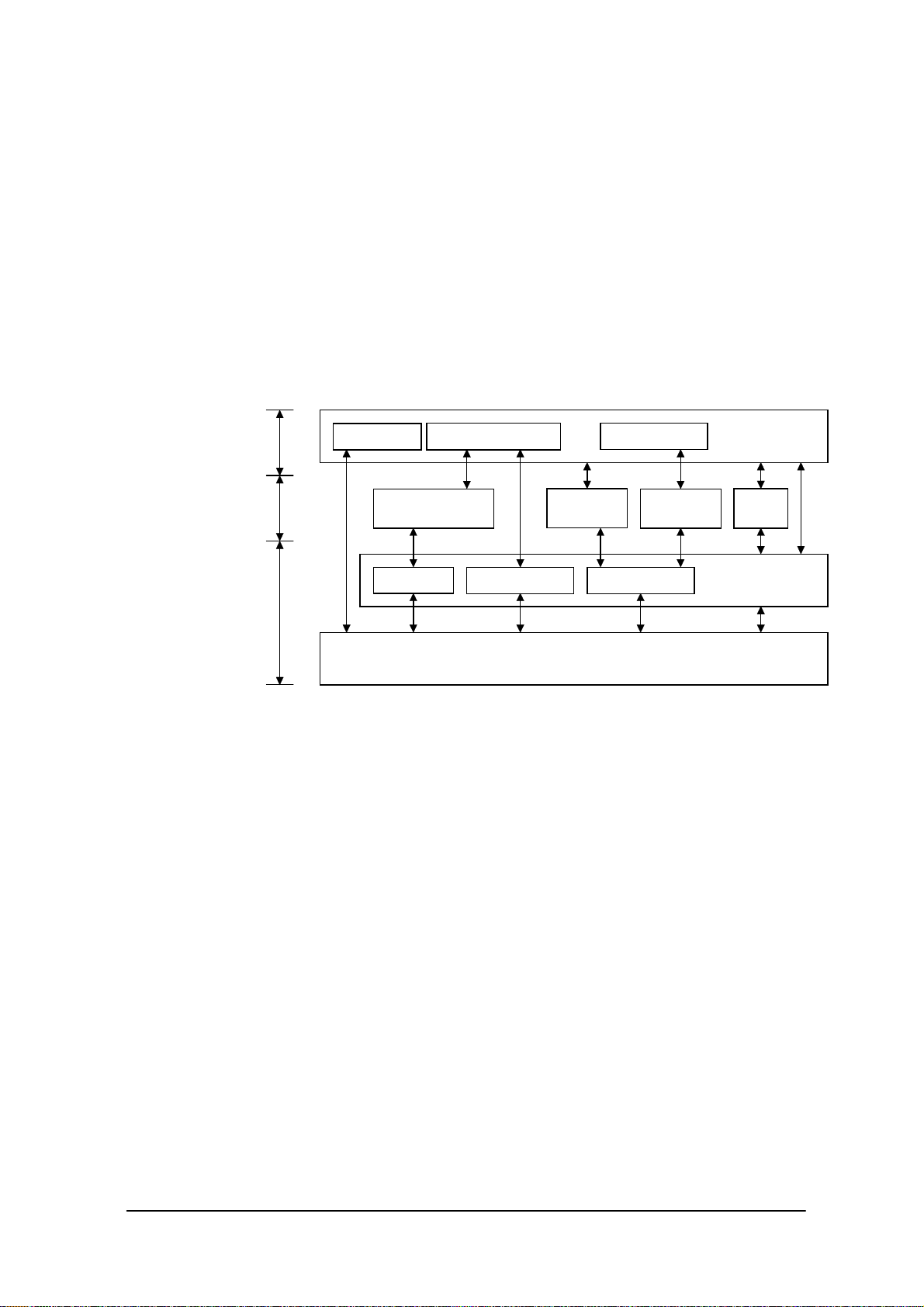
2.1.1 Software Configuration
The following diagram shows the software configuration of the IT-2000.
Driver
Keypad LibrarySystem Library
Int33h
Keypad
Driver
Pen BIOSExtended BIOSAPM BIOS
Application
Layer
MS-DOS
Layer
Hardware & BIOS
Layer
OBR Library
System Driver
PenMouse
AT Architecture + Original Hardware
Fig. 2.1
Note: The PenMouse driver and Keypad driver cannot co-exist on the system.
Application
MS-
DOS
ROM BIOS
15
Page 16

2.1.2 Memory Map
The memory map of the IT-2000 is as follows.
Extended Memory
ROM BIOS
NAND DISK BIOS/VGA BIOS
Memory Mapped Disk I/F
PC Card I/F
EMS Windows 16 KB x 4
Reserved
Video Buffer
128 KB
System RAM
640 KB
Fig. 2.2
100000h
0F0000h
0E0000h
0DC000h
0D8000h
0C8000h
0C0000h
0A0000h
000000h
16
Page 17

2.1.3 Drive Configuration
The drive configuration differs for each model as described in the following:
If F-ROM drive is supported
Drive A:
[Read and Write]
[Read Only]
[Read and Write]
[Read Only]
[Read Only]
[Read and Write]
RAM disk
This drive is prepared for use after the RAM disk size is specified from
the System Menu. The contents of this RAM disk will not be erased
through a boot process or by pressing the RESET switch.
Basic drive (DINOR FLASH ROM)Drive C:
This drive starts up MS-DOS. The main body of MS-DOS and
maintenance programs such as the System Menu, etc., are stored in this
drive.
F-ROM driveDrive D:
Application programs are stored on this drive. The drive size (storage
capacity) differs depending on the model.
Drive for Windows files (IT-2000W only)Drive E:
A ROM that stores Windows files is assigned to the drive E: on
Windows models.
This is a reserved drive on DOS models. In this case note that if this
drive is accessed , an INT24h error will occur.
Drive for booting a cardDrive F:
This read-only drive functions only while a card is being booted.
For information about the mechanism of booting a card refer to
Chapter 4.3 “Card Boot”.
PC card driveDrive G:
This drive is required if the application program accesses the PC card.
This drive is prepared for use by loading the PC card driver via
CONFIG.SYS.
Note:
The drive letter of each drive is reserved. Therefore, these drive letters are not changed even if the
RAM disk is not used.
The drive configuration described in "If F-ROM drive is not supported" on page 18 will be used
only if the drive D: is unformatted or is not recognized by the system for some reason.
However, this will rarely occur because the drive D: has been formatted at the factory.
17
Page 18

If F-ROM drive is not supported
Drive A:
[Read and Write]
RAM disk
This drive is readied for use after the RAM disk size is specified from
the System Menu. The contents of this RAM disk will not be erased
through a boot process or by pressing the RESET switch.
Basic drive (DINOR FLASH ROM)Drive C:
[Read Only]
This drive is used to start MS-DOS. In this drive not only the main body
of MS-DOS but also the maintenance programs such as the System
Menu, etc., are stored. This is a read-only drive.
Reserved driveDrive D:
[---]
This is a reserved drive.
If this drive is accessed, an INT21h error will result.
Drive for booting a cardDrive E:
[Read Only]
This is a read-only drive that functions only while a card is booted.
For information about the mechanism of booting a card refer to
Chapter 4.3 "Card Boot”.
PC card driveDrive F:
[Read and Write]
This drive is required if the application program accesses the PC card.
This drive is prepared for use by loading the PC card driver via
CONFIG.SYS.
18
Page 19
2.2 Basic System Operation
2.2.1 Overview
Basic operation of this system on the terminal consists of the suspend/resume process and boot
process operated by means of the Power switch and RESET switch, as shown in the following
diagram.
OFF STATE
OFF Process
OFF EVENT
System Menu
Fig. 2.3
During normal operation the system status will move between the ON state and the OFF state,
shown in the above diagram, by pressing the power key.
ON KEY
Application BOOT
RESET SWITCH
System Menu BOOT
RESET SWITCH
System Menu BOOT
ON KEY
System Menu BOOT
ON EVENT
ON Process
INITIAL STATE
ON STATE
OFF Process
OFF EVENT
SUSPEND
STATE
The SUSPEND state is a state from which the previous state can be returned to at any time. The
process of returning from the SUSPEND state to the ON state is called the resume process.
The RESET switch is used to either re-start the system or to initiate the System Menu, which is the
maintenance program. Press this RESET switch to start hardware initialization followed by initiation
of the System Menu. This process is called the System Menu boot process.
If an OFF event occurs while the System Menu is operating, the system shifts to the OFF state.
If the ON key is pressed in the OFF state, the boot process is executed again and an appropriate
application program will be loaded. This process is called the application boot process.
19
Page 20

The following table summarizes the power-on processes provided for this terminal.
System Menu boot
process
Application boot process Searches for CONFIG.SYS and AUTOEXEC.BAT prepared
Resume process Restores the memory conditions that existed before the power
Always executes CONFIG.SYS and AUTOEXEC.BAT located
in drive (C:) for starting up the MS-DOS.
by the user and starts up MS-DOS from the drive where they are
located.
was turned off and continues operating according to the
conditions.
20
Page 21
2.2.2 Power ON Process
Overview
The ON process is provided to make the system ready for use (ON state). The actual process varies
depending on the settings at that point in time and the last OFF factor (the cause of the OFF action).
ON factors:
Pressing the Power switch
Pressing the RESET switch
Power ON alarm
Reception of RING signal
Mounting on the I/O Box
OFF factors:
Pressing the Power switch
Pressing the RESET switch
Auto Power OFF (APO)
Power OFF by software
Auto Power OFF due to lower battery voltage
Emergency Power OFF due to lower battery voltage
Note:
For more information power OFF factors refer to Chapter 2.2.3 "Power OFF Process".
This ON process is divided into two processes: the "Resume process" for continuing the previous
process and the "Boot process" for re-loading MS-DOS. The Boot process can be further broken into
the "Application boot" and the "System Menu boot" processes.
Fig. 2.4
Boot Process
ON Process
Resume Process
Application Boot Process
System Menu Boot Process
Application Boot Process
Searches CONFIG.SYS and AUTOEXEC.BAT files according to the priority given to each drive
and, if these files are found, sets the drive where these files are located as the current drive.
(refer to ”Application Boot Process” on the next page).
21
Page 22

System Menu Boot Process
Pressing the RESET switch sets the drive C: as the current drive, and MS-DOS is loaded from
that drive. As a result, the System Menu that includes the maintenance program will be initiated
(refer to “System Menu Boot Process” on this page).
Resume Process
This process restores the conditions that existed before the power was most recently turned off.
Any application program that was running at that point in time can be continued.
The contents of the above listed processes will be described in the following sections.
Application Boot Process
The application boot process is used to initiate application programs that have been installed in the
system by the user. The main system will search for CONFIG.SYS and AUTOEXEC.BAT files
according to the priority given below.
The system assigns the first drive on which the files are found as the current drive, and boots MSDOS from the drive C. Consequently, if the CONFIG.SYS and AUTOEXEC.BAT files created by
the user are located on one drive, MS-DOS will be booted from the drive assigned as the current
drive. Under factory defaults it is apparent that the CONFIG.SYS and AUTOEXEC.BAT files
created by the user cannot be found. If this occurs, therefore, the CONFIG.SYS and
AUTOEXEC.BAT files located in the drive C: are selected and the System Menu will be initiated.
Priority of the drives:
If the F-ROM drive is provided
[Card drive (F:)] -> [RAM drive (A:)] -> [F-ROM drive (D:)] -> [Basic drive (C:)]
If the F-ROM drive is not provided
[Card drive (E:)] -> [RAM drive (A:)] -> [Basic drive (C:)]
Note:
The RAM disk (A:) is valid for use only if setup is made through the System Menu.
System Menu Boot Process
The System Menu boot process is used to initiate the System Menu, which is nothing but a
maintenance program for this terminal system. The System Menu boot process will be executed only
if the RESET switch at the rear of the main unit is pressed.
If, in addition, a power OFF factor is encountered during the execution of the System Menu, the next
boot process will be the Application boot process.
22
Page 23

Note:
The RESET switch can be used not only for initiating the System Menu but also as the forced
restart witch when the user application program under development hangs. However, note that if
the RESET switch is pressed while the disk is being written to, the data may be corrupted.
Therefore, the RESET switch should be pressed only while the power is off.
Clock data or information on the RAM disk will not be lost if the RESET switch is pressed.
Resume Process
When the power is turned on the resume function resumes system operation under the conditions
that existed the last time the power was tuned off. Application programs are continued as soon as the
power is resumed.
Setup of Resume Process ON/OFF
The default settings have been made so that every OFF factor encountered during the operation of an
application program is the objective of the resume process. However, these default settings can be
modified so that the system reacts differently to OFF factors by means of the system library. For
example, according to the default settings, pressing the Power switch will suspend and resume the
execution of an application program. However, it is also possible to simply reboot the system with
the Power switch without activating the resume function if such a setup is made. However, note that
this setup is not permanent. The resume process is replaced by the boot process once only right after
the system library is called.
ON Factors
Various ON factors used to turn on the system are explained below.
Pressing the Power switch
If the Power switch is pressed while the system is off, the system power can be tuned on. When
the power is turned on the system operation sequence proceeds as described in "Relationship
between OFF Factors and ON Processes" on page 24.
Pressing the RESET switch
Press the RESET switch to turn on the system power. In this case the System Menu will always
be initiated.
This terminal has the Auto Power ON function which automatically starts the system. This Auto
Power ON function can operate in one of the following three ways:
23
Page 24

Auto Power ON function (only affects the resume process) activated by alarm
The system power can be turned on (resumed) at the specified time by means of an alarm.
However, this will not function if the next start-up method is set to the boot process in the system
library.
Auto Power ON function activated by the RING signal
This function can be used if a modem is connected to the 14-pin expansion interface. In this case
the system power can be turned on by the detection of the RING signal from the modem.
Remember that Power ON by means of the RING signal is prohibited by default. Execute this
function using the system library to enable the Power ON function to be activated by the RING
signal. System operation after the power is turned on follows the sequence described in "
Relationship between OFF Factors and ON Processes" on this page.
Auto Power ON activated by mounting on the I/O Box
The system power can be automatically turned on as soon as this terminal is mounted on the I/O
Box. However, this function is effective only if power is supplied to the I/O Box. This function is
enabled by default, however, it can be disabled using the system library. System operation after
the power is turned on proceeds according to the sequence described in "Relationship between
OFF Factors and ON Processes".
Relationship between OFF Factors and ON Processes
As described in the above overviews, the ON process (the Boot process or Resume process) will run
differently depending on the last OFF factor (what caused the OFF) and the conditions that existed
when the power was turned OFF. The following table shows the relationship between the OFF
factors and the ON processes that take place the next time the power is turned on.
OFF factor If an application is running If the System Menu is on
Power switch
Auto Power OFF
Software OFF
Low battery voltage
(LB1)
Low battery voltage
(LB0)
RESET switch pressed System menu boot process System menu boot process
Note:
Depends on whether the resume function is enabled or disabled. With this setup the next boot
process can be designated as the Application boot process.
Resume process
or Application boot process
(see note below.)
Resume process
Application boot process
24
Page 25

2.2.3 Power OFF Process
Overview
Turns off the system power. However, the power to all the devices is not turned off and some can be
used for storing the information required for the next resume operation. This process is called the
suspend process and the state of the system while off is called the suspend state.
The suspend process can be divided into two categories: one is the normal suspend process which is
the usual off method and the other is the critical suspend process to execute the emergency escape
process for protecting the system from drops or bumps. Either of these suspend processes will be
selected depending on the OFF factor, as described later.
Normal Suspend Process
If the Power switch is held down for more than one second while system is on, the system power
will be turned off. The process that takes place at this time is the normal suspend process. Before
this suspend process is executed, the application currently running is informed of the suspend
request (OFF factor) by the system. Then the system stores the information required for resumption
and turns off the power.
Hereinafter the suspend process (or OFF process) refers to the normal suspend process.
For information about the method used by each application to detect the occurrence of an OFF factor
(suspend event), refer to Appendix C Acquisition of Suspend/Resume Event and Power Status.
Critical Suspend
This is a suspend process that takes place in an emergency. Since this critical suspend process should
achieve its escape process with very little power in the system, only essential information can be
retained.
The system will not inform the application currently running of the fact that it is critically
suspended. However, the application will be informed of the fact that it was critically suspended at
resumption.
For information about the method used by each application to receive this information, refer to
Appendix C Acquisition of Suspend/Resume Event and Power Status.
25
Page 26

OFF Factors
The OFF factors refer to various causes that make the system enter the OFF state (suspend state), as
follows:
OFF factor Description Suspend
Power switch System operation can be suspended by holding down
the Power switch for more than a second. (see note)
Auto Power OFF
(APO)
Software Power OFF The system can be made to enter the suspend state by
Power OFF due to
time-out of low
battery voltage
(LB1) alarm
If main battery
voltage falls to an
inoperable level
(LB0)
Power OFF due to
RESET switch
pressed
System operation automatically shifts to the suspend
state if key or touch panel operation is not performed
for a specified period of time.
The duration until Auto Power OFF occurs can be set
and modified through the System Menu or system
library.
calling the system library from the application
program.
The system will issue an alarm (buzzer) if the
remaining battery voltage falls below the low main
battery voltage alarm level. If this occurs, recharge the
battery or replace it within ten minutes. If the battery is
not replaced or recharged the system automatically
shifts to the suspend state to protect the data.
If the terminal is used while the LB1 alarm, mentioned
above, is sounding, the main battery voltage may reach
the LB0 level. If this occurs the system will execute
the critical suspend process and forcibly turn off the
power. Therefore, if the LB1 alarm sounds, recharge
or replace the battery as soon as possible.
Press the RESET switch to forcibly turn off the system
power. If this is attempted to initiate the System Menu,
it is strongly recommended to complete the application
running at present then turn off the system power with
the Power switch before hand.
Normal
Normal
Normal
Normal
Critical
Restart
For more information about LB0 and LB1, refer to Chapter 2.2.4, "Battery Voltage Monitoring
Process".
For information about the system library refer to Chapter 7.6.2. “System Library”.
For information about the System Menu refer to Chapter 3 “System Menu”.
For information about the method used by each application to acquire a power ON/OFF event, refer
to Appendix C Acquisition of Suspend/Resume Event and Power Status.
26
Page 27

Note:
Hold down the Power switch for more than one second until the power is off. This is done to
prevent the power from accidentally being turned off by the user. In addition, key input will not
be enabled for approximately one second after the Power switch has been pressed.
This occurs because the monitoring timer starts operating the moment the Power switch is
pressed and does not allow key input for about one second until this timer expires.
After this interval, key input becomes possible.
27
Page 28
2.2.4 Battery Voltage Monitoring Process
This terminal uses a main battery (lithium-ion battery pack) for driving the main unit, and a primary
sub-battery (lithium battery) and a secondary sub-battery (lithium-vanadium battery) for backup.
Application programs can acquire the status of these batteries through the APM BIOS or system
library. Refer to Appendix C Acquisition of Suspend/Resume Event and Power Status.
Battery Operation Scheme
The following diagram shows how each battery operates within the system.
Monitors
primary
sub-battery
voltage.
(LB2)
Fig. 2.5
[A] This is the power supply route where the fully charged main battery is installed.
While the power is on, the main battery supplies power to all the devices, including the main circuit,
PC card slot and DRAM, and, at the same time, it charges the secondary sub-battery.
Sub-battery
Primary
sub-battery
Objective devices of backup
[A] Charge
Secondary sub-battery
(Rechargeable)
[C]
(DRAM, etc.)
[B]
Main battery
(During ON)
[A]
Monitors main battery
voltage (LB1LB0)
[A]
(CPU and controllers, etc.)
[A](During ON)
PC Card Slot
Main circuit
SRAM Card
Monitors
SRAM card
voltage. (LB3)
In the suspend state, it stops the supply of power to the main circuit and PC card, but continues to
supply power to the DRAM and charge the secondary sub-battery. In this route neither the primary
nor the secondary sub-batteries are used.
[B] This is a power supply route operating where the main battery is absent or not fully charged.
The DRAM is back-upped by the voltage of the secondary sub-battery. The primary sub-battery is
not used.
[C] This power supply route operates if the main battery and secondary sub-batteries are not fully
charged. The DRAM is backed-up by the voltage of the primary sub-battery. If the voltage of this
primary sub-battery falls below the limit level, an LB2 event occurs.
28
Page 29

Low Voltage Level
The IT-2000 continuously monitors the voltage of the main battery, the primary sub-battery, and the
SRAM card battery. This allows an application program to determine through the system library if
the voltage of each battery reaches a warning level.
The following table summarizes the low battery voltage warning levels, which application programs
can acquire through the system library.
Name Abbreviat-
Low main battery
voltage warning level
Low sub-battery
voltage warning level
Low SRAM card
battery voltage
warning level
Objective
ion
LB1 Main battery Indicates that the main battery voltage
LB2 Sub-battery Indicates that the sub-battery voltage has
LB3 SRAM card
battery
battery
has reached a limit level that requires a
warning to be issued. The system sounds
the buzzer to issue an alarm. If this
occurs, the user must replace the main
battery within ten minutes. If the battery
is not changed within ten minutes, the
system automatically executes the
suspend process.
reached a limit level that requires a
warning to be issued. Since the system
does not issue an alarm, the application
program must execute a warning by
acquiring the status from the system
library.
The sub-battery must be replaced
according to the procedure described later.
Indicates that the SRAM card battery
voltage has reached a limit level that
requires a warning to be issued. Since the
system does not issue an alarm, the
application program side must execute a
warning by acquiring the status from the
system library. The SRAM card battery
must be replaced according to the
procedure described later.
Description
There is also a main battery inoperable level (LB0). This is the status of the main battery when its
voltage falls below LB1. If this happens, the system executes an emergency power off (critical
suspend). Therefore, this level is also referred to as the emergency escape process level.
This status cannot be acquired from the application side, since the system turns off the power as
soon as the voltage reaches LB0.
29
Page 30

Main Battery Voltage Monitoring
(a)
(c)
(d)
If the main battery voltage reaches LB1, the system issues a warning buzzer. If this warning buzzer
sounds, either start recharging the battery or replace it with a fully charged battery as soon as
possible.
If one of these measures is not taken within ten minutes, the system will forcibly turn off the power
for safety. The following diagram shows the main battery voltage against the time axis.
Main
Battery
voltage
LB1
Generate warning
buzzer.
Turn OFF power
automatically
(b)
Voltage level to
allow operation
Start to
recharge
LB0
(e)
10 minutes
Fig. 2.6
(a) If the main battery voltage reaches LB1, the low battery voltage warning alarm sounds.
(b) Unless the main battery is either replaced or recharged within ten minutes, the system power is
automatically turned off to protect the data.
(c) If the main battery voltage falls further and reaches LB0, the system automatically shuts off the
power to the main unit (critical suspend).
(d) If the main battery voltage drops below LB0, the main unit power cannot be turned on even if the
Power switch is pressed.
(e) If the main unit is mounted on the I/O Box or connected to the AC adaptor, charging of the
battery is initiated and the main battery voltage will gradually increase.
(f) Once the main battery voltage has been recharged to an operable level, it is possible to turn on
Time
the power to the main unit.
30
Page 31

For information about the method used to replace the main battery refer to Chapter 2.2.6 “
How to Replace or Recharge Batteries”.
Sub-battery Voltage Monitoring
The sub-batteries are used for system backup while the main battery is being replaced. The subbatteries consists of two units: the primary sub-battery (button-type lithium battery) and secondary
sub-battery (button-type lithium-vanadium battery). The secondary sub-battery is recharged by the
voltage of the main battery.
While the fully charged main battery is installed , the entire system is backed-up by the main battery,
and the secondary sub-battery is charged by the voltage of the main battery. If the main battery is
removed, the job of system backup shifts to the secondary sub-battery. If the secondary sub-battery
voltage drops below the required level while the main battery is removed, the backup job shifts to
the primary sub-battery (refer to “Battery Operation Scheme” on page 28.).
Application programs are permitted, through the system library, to monitor this primary sub-battery
voltage and determine if it is lower than the warning level (LB2). However the system side will not
issue a warning about the low voltage level (LB2) of the primary sub-battery. Therefore, the
application program must monitor the primary sub-battery voltage via the system library and inform
the user that it must be replaced.
For information about the method used to replace the sub-battery refer to Chapter 2.2.6,
“How to Replace or Recharge Batteries”.
SRAM Card Battery Voltage Monitoring
This function monitors the SRAM card battery voltage. Application programs are permitted, through
the system library, to monitor this voltage and determine if it is lower than the warning level (LB3).
However, the system side will not issue a warning about the low voltage level (LB3) of the SRAM
card battery. Therefore, the application program must monitor the SRAM card battery voltage via
the system library and inform the user that it must be replaced.
For information about the method used to replace the SRAM card battery refer to Chapter 2.2.6 “
How to Replace or Recharge Batteries”.
Acquiring Power Status through APM BIOS
This terminal has APM 1.1 installed. This makes it possible for application programs to obtain
information, such as the percentage of battery voltage remaining or the connector status, via the
APM BIOS. For more information refer to Appendix C Acquisition of Suspend/Resume Event and
Power Status.
31
Page 32

Acquiring Power Status through Battery Status Acquisition Utility
With the battery status acquisition utility the user can be advised of the current remaining voltage of
the main battery, sub-battery status, or connector status in real time. For more information refer to
Chapter 8.7 “Remaining Battery Voltage Display Utility”.
32
Page 33

2.2.5 Low Consumption Current Process
This terminal has (1) the APM BIOS installed to provide a low-power consumption capability.
It works in combination with POWER.EXE from Microsoft Corporation. The low-power
consumption capability is further enhanced by the use of unique power management functions,
including (2) Auto Power OFF (APO) function, (3) Auto Backlight OFF (ABO) function, and (4)
DOZE/RUN transition function.
Advanced Power Management Process (APM)
The APM process, which is an interface between the hardware and application programs, has been
developed by the Intel Corporation and Microsoft Corporation for power control purposes.
APM consists of four layers. The layers include hardware, APM BIOS, APM Driver, and the
application, as shown below. With respect to the PC card which is a removable device, the APM
functions are provided from the specific APM driver (CS_APM.EXE).
Applications Layer
OS Layer
BIOS Layer
Hardware Layer
Fig. 2.7
Basically, APM functions in the following two ways:
APM BIOS, which is in the background, controls the power conditions of each device.
APM-aware Applications
APM Driver (POWER.EXE)
APM BIOS
PC Card APM Driver
(CS_APM.EXE)
PC Card (Add-in Device)APM BIOS Controlled Device
Applications can call the APM BIOS functions to obtain or control the power conditions.
An application that uses the APM BIOS function is called an APM-aware Application. If an
application acquires information related to power conditions via the system library (refer to
Chapter 7.6.2 “System Library”), APM BIOS is actually called within the system library.
It is also possible to directly call APM BIOS from applications. For more information refer to
an APM BIOS manual published separately by a third party.
33
Page 34

Auto Power OFF Function (APO)
This function automatically shifts the system to the OFF state (suspend state) if no event has taken
place for a specified period of time from the touch panel, the keyboard, COM1, or a file.
This time interval has been set to one minute by default. It can be modified using the System Menu
or system library.
About the activity
Any access to the touch panel, key, COM1, or file that causes results in Auto Power OFF is
defined as "an activity", and it is said that "an activity occurs" if one of these devices is accessed.
In other words, the Auto Power OFF function can be said to have shifted the system to the
suspend state if no activity has occurred for a specified period of time.
The term "activity" is also used in the later description of the ABO function, but it has a different
meaning.
Activity monitored by APO:
Touch panel input
Key input
Access to files
Access to COM1
Auto Backlight OFF Function (ABO)
This function automatically turns off the backlight if no access to the touch panel or keys has been
attempted for a specified period of time. This time interval has been set to twenty seconds by default.
It can be modified using the System Menu or system library. Touch panel or key sensing is
performed by the keyboard controller. This keyboard controller not only processes key input or
touch panel input, but it also simultaneously detects activity while executing various background
processes. Consequently, the limit value set as the Auto Backlight OFF time will not be accurate
down to the seconds. The accuracy of this setup value is10 percent.
Activity monitored by ABO:
Touch panel input
Key input
34
Page 35

DOZE/RUN Transit Function
On this terminal the system will reduce the clock speed of the built-in CPU if no activity (access to
the touch panel, keys, COM1, or file) has occurred for a specified period of time (four seconds).
The state in which the CPU clock speed has been reduced is called the "DOZE state" and the state in
which the CPU is operating at full speed is called the "RUN state". If an activity occurs in the
DOZE state, the system returns to the RUN state. The DOZE/RUN transit function automatically
switches between the DOZE and RUN states.
Touch panel
No activity for
a specified period
of time
Key
COM1
File access
RUN
Full speed
Generation of
Activity
Touch panel
Key
COM1
File access
DOZE
Low speed
Fig. 2.8
Usually, application programs do not have to anxious about the RUN/DOZE state.
The user may tolerate the operation speed since the system shifts to the RUN state whenever the user
attempts an action.
However, the clock speed is quickly reduced and CPU operation is slow if high-speed processing is
attempted intentionally or if system operation continues without user action (e.g. in a long
calculation).
In order to avoid this, disable the power management function by means of the system library (refer
to Chapter 7.6.2 “System Library”.).
Activity causing RUN/DOZE transition:
Touch panel input
Key input
Access to files
Access to COM1
35
Page 36

Note:
If the power management function is disabled by the system library, the Auto Power OFF function
(APO) is also disabled. This is because both the power management function and Auto Power OFF
function use the same activity processing routine.
36
Page 37

2.2.6 How to Replace or Recharge Batteries
Replacement of Batteries
The method used to replace the main battery, sub-battery, and SRAM card battery are explained
here. Failure to observe the correct battery replacement procedure may result in a loss of data.
Always observe the following steps in battery replacement.
Main battery replacement
Hold down the Power switch for more than one second to turn off the main unit power.
Make sure that two sub-batteries are installed, then open the battery compartment lid.
Replace the fully charged main battery, the close the battery compartment lid.
Note:
Make sure that both sub-batteries are installed. If either of the sub-batteries is not installed,
the data may be lost.
Do not open the battery compartment lid while the power is on. If it is opened accidentally, an
emergency alarm sounds. In case such the event occurs, close the lid at once.
Sub-battery replacement
Hold down the Power switch for more than one second to turn off the main unit power.
Make sure that the fully charged main battery is installed.
Replace the primary sub-battery (button-type lithium battery) with a new one.
Note:
Make sure that the main battery is installed. If the primary sub-battery is removed without the
main battery being in place, data will be lost.
The secondary sub-battery (button-type lithium-vanadium battery) does not have to be replaced.
SRAM card battery replacement
Make a backup of the SRAM card on the F-ROM drive or on some other device.
Remove the SRAM card from the PC card slot of the main unit.
Replace the battery of the SRAM card.
Insert the SRAM card into the PC card slot.
If the data has been lost, format (refer to Chapter 2.3.6 “PC Card”) the SRAM card then
restore the data on it from the backup device.
37
Page 38

Note:
The SRAM card is supplied power by the main battery when it is installed in the main unit. This
means that the SRAM card can be used normally as long as it is in the slot, even if the voltage of the
card battery is zero.
In this case, however, the data on the SRAM card will be lost when the card is removed from the
main unit slot. Since the Casio SRAM card is provided with two batteries, the data will not be lost
for a short while even if one of them is removed. However, it is recommended that the SRAM card
battery be replaced only after making a backup of the data to avoid accidental loss.
Main Battery Recharge
The main battery can be recharged using either of the following methods:
Recharging with the charger
According to the "Main battery replacement" procedure described on the previous page, remove
the main battery and place it on the charger.
Recharging with the AC adaptor
While keeping the main battery to be recharged in the main unit, insert the AC adaptor plug in
the charging jack located on the side of the main unit. This starts the recharging operation.
Recharging with the I/O Box
If the main unit is mounted on the I/O Box while the main battery to be recharged is in the main
unit, the charging operation starts.
38
Page 39

2.3 Supported Devices
2.3.1 Display Unit
Hardware Configuration
LCD FSTN semi-transparent liquid crystal display
Resolution 192 x 384 dots
Tone B/W 16 gray scales (4 gray scales are identifiable)
Method VGA compatible
VRAM 512 KB
RAM for hardware window 32 KB
Note:
With B/W liquid crystal displays the actual display colors will be changed to reverse video.
About the Display Screen
Since this terminal has a VGA controller, it can internally control the entire VGA (640 x 480 dots)
screen. However, only the 192 x 384 dots, which corresponds to the upper left portion of the VGA
screen, can be displayed.
Fig. 2.9
39
Page 40

Software Functions
Standard Video BIOS is supported. This supports the following video modes:
Mode No Mode Type Characters Resolution Colors Memory Segment
00h Text 40 x 25 320 x 200 16 B800h
01h Text 40 x 25 320 x 200 16 B800h
02h Text 80 x 25 640 x 200 16 B800h
03h Text 80 x 25 640 x 200 16 B800h
04h Graphics 320 x 200 4 B800h
05h Graphics 320 x 200 4 B800h
06h Graphics 640 x 200 2 B800h
07h Text 80 x 25 640 x 350 2 B000h
0Dh Graphics 320 x 200 16 A000h
0Eh Graphics 640 x 200 16 A000h
10h Graphics 640 x 350 16 A000h
11h Graphics 640 x 480 2 A000h
12h Graphics 640 x 480 16 A000h
Hardware Window
The hardware window provides the superimpose function for the VGA controller.
With this hardware window a pop-up screen can be displayed without affecting the operation of
the application program. This hardware window is used in the keypad driver and various utility
programs.
Contrast Adjustment
The contrast of the liquid crystal display automatically compensates for temperature changes.
The user can adjust the offset value (refer to Chapter 5 “Keyboard Controller”) for the automatically
adjusted contrast in the following ways.
Press the 8 key after the Fn key to increase the contrast offset one step.
Press the 9 key after the Fn key to decrease the contrast offset one step.
Call the system library to increase/decrease the contrast offset.
40
Page 41

2.3.2 EL Backlight
Overview
This terminal has the following functions to control the backlight. For more information refer to
Chapter 5, “Keyboard Controller”.
Manual Backlight ON/OFF function
Auto Backlight OFF function (ABO)
Auto Backlight Control function (ABC)
Manual Backlight ON/OFF Function
The backlight can be turned on and off with the following methods.
Press the 7 key after the Fn key to turn on or off the backlight.
Call the system library to turn on or off the backlight.
Auto Backlight OFF Function
This function automatically turns off the backlight when no key or touch panel input has been
occurred in the specified period of time. The time interval until the backlight is automatically turned
off can be set with the System Menu or the system library.
Auto Backlight Control Function
This function detects the intensity of ambient light and automatically turns on or off the backlight
accordingly. This function is set to off by default, however, it can be set to on using the System
Menu or system library. For more information about the system library refer to Chapter 7.6.2 “
System Library”.
41
Page 42

2.3.3 Touch Panel
Hardware Configuration
Method : Analog type touch panel
Resolution : 192 x 384 dots
Software Function
To enable application programs to acquire touch panel coordinates, the following two pieces of
software are provided:
PENMOUSE.COM
With this PENMOUSE.COM application programs can acquire touch panel input through the
mouse I/F. (refer to Chapter 6.5 “PenMouse Driver”.)
KEYPAD.EXE
With this keypad driver application programs can perform character input through the touch
panel. However, it cannot be used concurrently with PENMOUSE.COM. (refer to Chapter 6.4
“Keypad Driver / Hardware Window Manager”.)
42
Page 43

2.3.4 Disk
Types of Disk
Type Drive name Capacity
RAM disk A 0 to 1920 Kbytes
Basic drive C 768 Kbytes
F-ROM disk D 0, 4, 8, 12, 16 or 24 Mbytes
PC card G or F SRAM card, ATA card
Note:
The drive name of the PC card varies for each model. For more information refer to Chapter 2.1.3
“Drive Configuration”.
RAM Disk
Part of the main RAM can be assigned on the RAM disk using System Menu.
The contents of the RAM disk will not be erased if the Power switch is turned on and off, since they
are backed-up by the main battery and the sub-batteries. The contents of the RAM disk are not
affected by pressing the RESET switch either. Since this RAM disk permits the use of INT13h, it
can be used as the built-in fixed disk. Its drive name is A.
Note:
Since the RAM disk shares part of the main memory installed in the main unit, a large-size RAM
disk may affect the operation of application programs.
Basic Drive
Part of the DINOR FLASH ROM is used as the basic drive. It cannot be written to.
Disk capacity : 768 KB
Since the basic drive supports the INT13h (Read Only) interrupt, it can be used as the built-in fixed
drive. Its drive name is C.
43
Page 44

F-ROM Drive
The F-ROM drive is supported as a disk for which both read and write operations are possible (only
for models with the F-ROM drive). Various disk capacities are supported for each model:
Disk capacity: 0 (models without F-ROM), 4M, 8M, 12M, 16M or 24 MB
To format the F-ROM drive use the System Menu. For information about the formatting method
refer to Chapter 3 “System Menu”. In this process the System Menu will call TFORMAT.EXE from
drive (C:) to format the F-ROM drive.
For more information about the TFORMAT.EXE operation refer to Appendix A TFORMAT.
Since this F-ROM drive supports the INT13h interrupt, it can be used as the built-in fixed drive. Its
drive name is D.
PC Card Drive
If either an SRAM card or ATA F-ROM card is inserted in the PC card slot, it can be used as the
drive G (Drive F for models without the F-ROM drive). If the ATA F-ROM card is inserted in the
card slot, the system can boot up according to the CONFIG.SYS/AUTOEXEC.BAT files included
on this card. This start-up method is called "card boot".
For more information about card boot refer to Chapter 4.3 “Card Boot”.
44
Page 45

2.3.5 Serial Communication
Available Interfaces
Port I/O Address Name Uses Remark
COM1 3F8h-3FFh 8-pin serial I/F Connection with a barcode
reader or PC
COM2 2F8h-2FFh
COM3 3E8h-3EFh (Modem card) Modem card If a modem card is
COM4 2E8h-2EFh IrDA 1.1 Communication with an I/O
14-pin serial I/F Connection with an
expansion I/F device
IrDA 1.0 Communication with an I/O
Box or between two IT2000s
Box or between two IT2000s
COM1
This is a COM port for RS-232C communication. This port can be used after turning on the power to
the 8-pin serial I/F via the system library. The 8-pin serial I/F is located on the side panel of the main
unit.
Can be switched
via the system
library.
used.
Direct control not
possible
Signal Pin 1. SD
Fig. 2.10
Pin 2. RD
Pin 3. RS
Pin 4. CS
Pin 5. Vcc
Pin 6. GND
Pin 7. ER
Pin 8. DR
45
Page 46

COM2
Either the 14-pin serial I/F or IrDA 1.0 can be assigned to this COM2 port depending on the system
library setup. Both the 14-pin serial I/F and IrDA 1.0 can be used as a normal RS-232C interface. By
default, the COM2 channel is not assigned to either device. Therefore, always use the system library
to designate either the 14-pin serial I/F or IrDA, then turn on the power. The 14-pin serial I/F is
located on the rear of the panel.
Pin 1. GND
Pin 2. GND
Pin 3. N.C.
8
9210311412513614
1
Fig. 2.11
7
Pin 4. SD
Pin 5. RD
Pin 6. RS
Pin 7. ER
Pin 8. CS
Pin 9. CI
Pin 10. DR
Pin 11. CD
Pin 12. EXTSW
Pin 13. VH
Pin 14. VH
COM3
A modem card, if one is inserted in the PC card slot, can be used as the COM3 port.
(refer to Chapter 2.3.6 “PC Card”.)
COM4
The COM4 port is dedicated for IrDA 1.1. It is used internally by the FLINK utility. Therefore, it
cannot be directly controlled by application programs.
46
Page 47

2.3.6 PC Card
Hardware Overview
Standard Conforms to PCMCIA Release 2.1
Register compatibility Has register compatibility with Intel 82365SL Step
Slot 1 slot TYPE II
Power supply Vcc : 5V (not operable at 3.3V)
Card lock switch Has a card lock switch
Recommended PC Cards
Type Model name
SRAM card DT-635MC (256 KB)
DT-636MC (512 KB)
DT-637MC ( 1 MB)
ATA Flash ROM card DT-9031FMC ( 2.5 MB)
DT-9032FMC ( 5 MB)
DT-9033FMC (10 MB)
DT-9034FMC (20 MB)
How to Format SRAM Card and ATA F-ROM Card
To format, call FORMAT.COM in the basic drive (C:). Then, in the DOS prompt screen that
appears, execute the following command to format the SRAM card or ATA F-ROM card.
FORMAT.COM can also be called as a child process.
FORMAT G:
COM Port of Modem Card
COM Port COM3
IRQ 11
I/O Address 3E8h to 3EFh
Notes:
This port is not applicable for a 3.3V card, CardBus, or a ZV port.
Neither turn off the power nor remove the card while accessing the card. If this is done, system
operation becomes unstable.
Before using each type of PC card the PC card driver should be installed by means of the
CONFIG.SYS file. For information about the method used to write CONFIG.SYS refer to
Chapter 4.2 “How to Write CONFIG.SYS/AUTOEXEC.BAT”.
If the PC card is inserted in the slot and the card is locked, a card recognition sound (buzzer) will
be issued. Since the card is locked, a short period may be required until the recognition sound is
actually issued. Therefore, it is necessary to confirm this recognition sound in advance if
accessing to the card. An error may occur if the card is accessed before the recognition sound is
issued.
47
Page 48

Card Lock Switch
The IT-2000 has a card lock switch to prevent accidental removal of the card. Any card can be made
usable only after it has been inserted in the slot and the switch has been locked properly. However,
since some types of cards do not allow this card lock switch to be closed, a library routine to disable
this switch is supported. For more information refer to Chapter 7.6.2 "System Library”.
48
Page 49

2.3.7 Clock Timer
Clock BIOS
00h to 07h of the INT1Ah function are compatible with the IBM PC/AT.
Since INT1Ah can be called in the C language, an alarm operation using the clock can be set with
the system library.
Alarm
If an alarm operation is set using the INT1Ah or system library, it is possible to cause an INT4Ah
interrupt at the specified time to issue the alarm. Normally a buzzer sounds if an INT4Ah occurs,
however, the application program side can hook this interrupt and perform its unique alarm process.
It is also possible to automatically turn on the power at the specified alarm time by means of the
system library (refer to Chapter 7.6.2 “System Library”).
49
Page 50

2.3.8 Buzzer
This terminal is provided with a buzzer function that is compatible, via an appropriate interface, with
the IBM PC. The application side can sound this buzzer by controlling the I/O port assigned to 61h.
It is also possible to modify the sound frequency by controlling channel 2 of the timer.
For information about the method used to modify the frequency refer to the hardware manual of the
PC/AT compatible machine.
Use of Buzzer From the System
The IT-2000 system uses the buzzer in the following cases:
At power on (boot)
If the power is turned off by the Power switch.
If the PC card is inserted/removed
If a key input is accepted (for matrix key and keypad). Enable/disable can be set with the system
library. (refer to Chapter 7.6.2 “System Library”)
If the key buffer is full
At a low battery voltage (LB1)
If an alarm interrupt (INT4Ah) occurs
If the battery cover is opened while the power is on.
At a hardware anomaly
For calibration and System Menu operation
Setting Volume of Buzzer
The buzzer volume can be set with System Menu or from the system library.
The volume can be set to one of the four levels: OFF/Small/Medium/Large.
For more information about System Menu and the system library refer to Chapter 3 “System Menu"
and Chapter 7.6.2 “System Library” respectively.
50
Page 51

2.3.9 Barcode Reader
Overview
The IT-2000 supports the following two Casio OBR (Optical Barcode Reader) models:
DT-9650BCR ( Pen scanner )
DT-9656BCR ( CCD scanner)
Connect the OBR to the COM1 (8-pin) port of this terminal, and set up the interface as follows.
Synchronization asynchronous
Baud rate 9600 bps
Data bit 8 bits
Parity bit none
Stop bit 1 bit
For communication between the OBR and this terminal use the OBR library. The various settings
such as an objective readout codes can be set up by transmitting the set up commands from this
terminal to the OBR.
Notes:
The OBR power is controlled by the OBR library function.
Before connecting the OBR to this terminal, turn off the main power.
Every OBR can write the current setup values in the EEPROM built into each OBR.
This ensures that the setup data is retained even when the power is off.
For more information about the OBR library, refer to Chapter 7.6.4 “OBR Library”.
51
Page 52

2.3.10 Infrared Communication (IR)
The infrared communication function of this terminal supports the protocol of IrDA 1.0
(see note below) and IrDA 1.1 standards. IrDA 1.0 can be used as the COM port for a general
RS-232C. IrDA 1.1 can provide communication at a maximum rate of 4 Mbps by means of
the dedicated utility (FLINK utility).
IrDA 1.0
Item Specification Remark
Synchronization asynchronous Conforms to IrDA1.0
Baud Rate 115.2 Kbps max.
COM Port COM2
IrDA 1.1
Synchronization Frame synchronization Conforms to IrDA1.1
(see note below)
Baud Rate 4 Mbps max.
COM Port COM4 Cannot be controlled directly
from the application.
Note:
The distance between the two ports must not be more than 60 cm (or 23.6 inches) apart.
52
Page 53

2.3.11 Keys
Hardware Overview
Key configuration 5 (column) x 3 (row) keys
IRQ IRQ1
Key repeat function available
Simultaneous pressing
of multiple keys
Roll-over function not available
Key Layout
See the following key layout.
Fn 7 8 9 -
4 5 6
0 1 2 3
Fig. 2.12
not available
CLR
Fn key
The "Fn" key should be used in combination with the numeric key. Hold down the "Fn" key and
press a numeric key.
Fn -> 0 Function key F10
Fn -> 1 to 6 Function key F1 to F6
Fn -> 7 Backlight on/off
Fn -> 8 Increase the contrast
Fn -> 9 Decrease the contrast
For more information refer to Chapter 5 “Keyboard Controller”.
53
Page 54

2.3.12 Sensors
The IT-2000 has the following three types of built-in sensors:
Illumination
sensor
Temperature
sensor
Battery voltage
level sensor
Attached to the upper section of this terminal and used to sense the ambient
light intensity. It is used for the Auto Backlight Control (ABC) function.
It cannot be controlled directly from the application.
(For more information about the system library refer to Chapter 5 “Keyboard
Controller”.)
Attached to the inside of the main unit and used to detect the ambient
temperature. It is used for Automatic Brightness Adjustment (ABA) of the
liquid crystal display. It cannot be controlled directly from the application.
(For more information about the system library refer to Chapter 5 “Keyboard
Controller”.)
Detects the voltage levels of the main battery, sub-batteries, and card
battery. It is used by the system to take action against low battery voltages.
The system manages low voltage through this battery electric potential sensor.
Applications can acquire the information from this battery voltage level
sensor via the system library or APM BIOS.
(Refer to Chapter 2.2.4 “Battery Voltage Monitoring Process”.)
54
Page 55

3. System Menu
3.1 Overview
The system menu is a program and used to perform various setups (system clock, contrast of
liquid crystal display, etc.) and implement (downloading) application programs, all of which
are necessary to use this terminal.
To start up the system menu press the reset switch located at the back of the main unit.
When the reset switch is released a short beep will sound and, after a short while, a screen as
shown in Fig. 3.1 will appear.
The calibration (touch panel adjustment) program is initiated first and it must be executed
before entering to the system menu selection stage. If this terminal is used for the first time or
if the touch screen is out of line, adjust the touch panel using this calibration program.
(For information about adjusting the touch panel refer to Chapter 3.9 “Touch Panel Calibration”)
If the “ 1” key is pressed the system menu will be initiated as shown in Fig. 3.2.
Fig. 3.1 Fig. 3.2
55
Page 56

3.2 Basic Operation
In the system menu a common set of key operations are used. The following list shows the
keys that can be used in the system menu.
Current Condition Key Operation Operation Process
Line cursor is on
Others
If "FILE TRANSFER" or "MAINTENANCE" is selected for the first time after the system
menu is initiated, the operator is required to enter a password for system security purposes.
8 Moves the line selection cursor up one line.
2 Moves the line selection cursor down one line.
CLR Moves the line selection cursor to the upper
menu area, if it is located in the lower menu
area.
RET Confirms and executes the currently selected
menu item.
0 to 9 Selection of an item or entry of a numeric
value.
RET Confirms the currently selected execution item.
CLR Cancels the currently selected execution item.
For information about password entry refer to Chapter 3.17 “Password Entry".
3.3 List of Functions
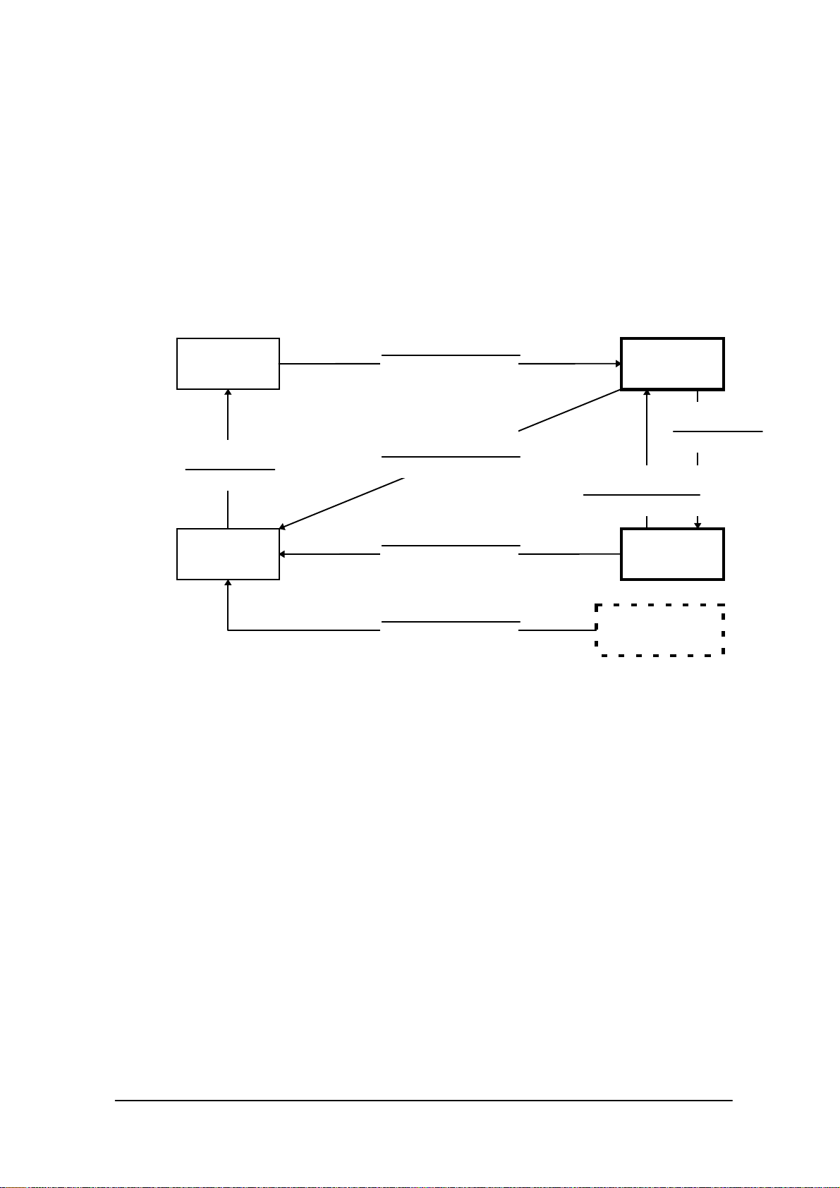
Command Screen Description
SYSTEM SETUP
(requires password)
MAINTENANCE
(requires password)
EXIT (power off)
Key Click Sound Switch ON or OFF the key click sound.
Buzzer Volume Set volume of buzzer.
LCD Contrast Adjust the brightness of contrast.
Auto Backlight Set the control of auto backlight.
Auto Power OFF Set auto power off.
Calibration Adjust the calibration on touch panel.
Ymodem Batch Start up the YMODEM utility.FILE TRANSFER
FLINK (IrDA) Start up the FLINK utility.
Set Date/Time Set date and time.
MS-DOS Command Set the command entry mode.
RAM Disk Size Change the size of RAM DISK.
Format Disk Format on user disk.
Default Setting Start up the system initialization.
For information about each function in the list above refer to the following pages.
56
Page 57

3.4 Key Click Sound Setup
Function
Sets the key click sound ON and OFF. If it is set to ON, a key click sound is heard when a key
is pressed or when the keypad is touched. It does not sound if it is set to OFF.
Fig. 3.3
Operation
Select ON/OFF with the “ 0” or “ 1 “ key, then confirm the selection with the “RET” key.
Key Operation Function
0 key Sets the key click sound to OFF.
1 key Sets the key click sound to ON.
. (decimal) key
RET key Confirms the current setup and exits the current operation.
CLR key Cancels the setup and exits the current operation.
Others Invalid.
Toggles to ON and OFF of the key click sound.
57
Page 58

3.5 Buzzer Volume Setup
Function
Sets the volume of the buzzer (beep). One of the four levels (OFF/Small/Medium/Large) can
be selected.
Fig. 3.4
Operation
Make a selection with a key, “ 0” to “ 3 “, and confirm the selection with the “ RET” key.
Key Operation Function
0 to 3 keys Selects the corresponding number.
. (decimal) key Toggles between two selections.
RET key Confirms the currently selected setup and exits this operation.
CLR key Cancels the currently selected setup and exits this operation.
Others Invalid.
58
Page 59

3.6 Contrast Adjustment
Function
Adjusts the contrast of the liquid crystal display.
Fig. 3.5
Operation
Press the “8 “ key to increase the contrast or press the “ 2” key to decrease the contrast.
Press the “ RET” key to confirm the setting.
Key Operation Function
8 key Increase the contrast.
2 key Decrease the contrast.
RET key Confirms the currently selected contrast setup and exits this
operation.
CLR key Cancels the currently selected contrast setup.
Others Invalid.
Note:
Depending on whether the parameters are being modified, the CLR key activates differently.
For example, if the CLR key is pressed while a parameter is being changed, that parameter
will be reset to the previous value.
However, if the CLR key is pressed while no parameter is being changed, the setup process will
be aborted and exited at that point.
59
Page 60

3.7 Auto Backlight Setup
Function
Sets the auto backlight control ON or OFF (refer to Chapter 5 “Keyboard Controller").
Fig. 3.6
Operation
Select ON/OFF with the “ 0” or “ 1” key, then confirm the selection with the “RET” key.
Key Operation Function
0 key Turns the auto backlight control to OFF.
1 key Sets the auto backlight control to ON.
. (decimal) key Toggles to ON and OFF of the auto backlight control.
RET key Confirms the current setup and exits this operation.
CLR key Cancels the current setup and exits this operation.
Others Invalid.
60
Page 61

3.8 Auto Power OFF Setup
Function
Sets the time-out period of the auto power off function (APO) (refer to Chapter 2.2.3 “Power OFF
Process"). This time-out period is the interval between when no key entry or no entry on the
touch panel is made and when the power of system is shut off automatically.
Fig.3.7
Operation
Set the APO time out period with the “ 2” or “ 8 “ key, then confirms the setting with the
“ RET” key.
Key Operation Function
8 key Increase the APO timeout period.
2 key Decrease the APO timeout period. If "DISABLE" appears,
the APO function is disabled.
RET key Confirms the current setup and exits this operation.
CLR key Cancels the current setup and exits this operation.
Others Invalid.
61
Page 62

3.9 Touch Panel Calibration
Function
Adjusts the calibration of touch panel. If an inconsistency is noted between the target position
and the position actually touched on the touch panel, correct it by performing this calibration
adjustment.
Fig. 3.8
Operation
Adjustment of the calibration :
When the buzzer sounds, release the stylus from the touch panel.
If any improper operation has been done, press the “1” key to perform the touch panel
calibration again.
If the “2” key is pressed after the four positions have been touched, the calibration
adjustment result takes effect and the menu screen is restored. However, if the “ 2 “ key is
pressed before finishing on the fourth position, the adjustment process performed so far will
be canceled.
62
Page 63

Note:
If an
mark has been touched by the stylus, an incorrect position was likely touched. Touch the correct
position.
mark does not disappear and the arrow does not move to the next position even if the
Key Operation Function
1 key Adjusts the touch panel calibration starting from the beginning.
2 key Returns to the menu screen.
Others Invalid
63
Page 64

3.10 YMODEM Utility
Function
Used to achieve a file transfer via the COM cable.
Communication can be established either between an AT-compatible machine (PC) and an
IT-2000 (main unit), referred to as "PC-to-HT communication". A dedicated 9-pin DSUB-8-pin
cross-type cable (DT-9689AX) is required to connect both the terminals. This utility does not have
functions to allow communication between HT and HT. Use the FLINK function for the HT-to-HT
communication.
Fig. 3.9
Fig. 3.10 Fig. 3.11
64
Page 65

Note:
When the cable comes off while the communication takes place:
If the connection cable is accidentally unplugged while communication between the IT-2000 and PC
is taking place, a communication error results and communication is interrupted. In this case the
communication software on the PC will display an error message and interrupt
transmission/reception, however, some data may remain in the transmission buffer. If an attempt is
made to restart communication in this condition, the XY utility may receive illegal packets,
hampering normal communication. If this occurs, terminate the communication software on the PC
side then restart it to restore normal communication.
About time stamping of files:
This utility supports the function to exchange time stamp information between the transmitted file
and received file. The time stamp information to be exchanged will be processed assuming that it is
Greenwich standard time. In contrast, the time used by the IT-2000 is the local time, and the time
stamp of IT-2000 files are accordingly controlled based on the local time.
The XY utility, for file transmission/reception by means of the YMODEM protocol, will convert a
time stamp in Greenwich standard time to a time stamp in local time, or vice versa. This time
conversion is achieved according to the environment variable, TZ. In communication between two
IT-2000 terminals, if, for example, TZ of the transmission side is "JST+5", the time stamp of a file to
be transmitted will have five hours added. In this case the reception side will create a file by
subtracting five hours from the time stamp of the received file.
If the environment variable TZ is not set, this time conversion is not performed.
The time stamp made at XMODEM communication uses the system time of the reception side.
Transmission side Reception side
IT-2000(TZ=none)
IT-2000(TZ=GMT)
IT-2000(TZ=JST+5)
IT-2000(TZ=JST+5)
PC
12:00
12:00
12:00
12:00
12:00
0
0
+5
+5
?
12:00
12:00
17:00
17:00
??:??
0
0
-5
?
-5
12:00
12:00
12:00
??:??
(??-5):??
IT-2000(TZ=none)
IT-2000(TZ=GMT)
IT-2000(TZ=JST+5)
PC
IT-2000(TZ=JST+5)
About key input during communication
Do not press any key during communication, otherwise file transmission/reception may be
hampered.
65
Page 66

Operations
(1) SEND FILE TO HT (one file transmission from IT-2000 to IT-2000)
This function may be available in future (as of now, not available). It is not allowed to use the
function. If the file transmission between IT-2000s is needed, FLINK utility may be used (refer to
Chapter 3.11 “FLINK Command”.).
(2) SEND FILE TO PC (one file transmission from IT-2000 to PC)
This function is used to copy an optional file from an IT-2000 to PC. To do this, use
commercial terminal emulation software on the PC side. The destination directory of this
copy should be specified by the terminal emulation software on the PC side.
Connect one end of the serial cable (cross-type) to the 8-pin COM port of the IT-2000 and
connect the other end to the COM port of the PC.
Select "SEND FILE TO PC" on the transmission side.
On the PC side initiate the terminal emulation software to prepare for download.
Select a baud rate of 9600 bps, and specify the YMODEM Batch protocol.
When the file name input screen appears on the IT-2000 side, specify the transmitted file
with its full path name (including the drive name), then press the “RET” key.
Pressing the “RET” key starts file transfer. When the "Normal End" message is displayed, file
transmission has been completed.
If the “CLR” key is pressed during file transfer, transfer will be interrupted. It will take about
10 seconds for communication to completely stop.
(3) SEND ALL TO HT (transfer all files in the user drive of IT-2000 to IT-2000)
This function may be available in future (right now, not available). It is not allowed to use the
function. If the file transmission between IT-2000s is needed, FLINK utility may be used (refer to
Chapter 3.11 “FLINK Command”.).
(4) RECEIVE FILES (file reception)
The function is used to receive one file from the PC.
For information about the method used to receive a file from the IT-2000, refer to the "SEND
FILE TO HT" description. On the PC side commercial terminal emulation software must be used.
In this operation the copy destination directory cannot be specified.
Connect one end of the serial cable (cross-type) to the 8-pin COM port of the IT-2000 and
connect the other end to the COM port of the PC.
Move the cursor to " RECEIVE FILES ", then press the “ RET” key to prepare for reception.
Start upload with the terminal emulation software on the PC side.
Select a baud rate of 9600 bps, and specify the YMODEM Batch protocol.
66
Page 67

When the "Normal End" message is displayed on the IT-2000 side, file reception has been
completed. For information about the copy destination directory refer to the following table.
If the “CLR” key is pressed during communication, file reception will be interrupted. It
will take about 10 seconds for communication to completely stop.
The destination drive/directory will vary depending on whether the destination side has an
FROM drive (D:) and/or RAM disk (A:). The following table shows the possible destination
drive/directory for copy purposes.
FROM drive (D:) RAM disk (A:) Copy destination drive/directory
Installed FROM drive (D:)Installed
Not installed FROM drive (D:)
Installed RAM disk (A:)Not installed
Not installed Error
67
Page 68

3.11 FLINK Command
Function
Files can be transferred by infrared communication (IR). This can be implemented either as PC-toHT (AT-compatible machine to IT-2000) communication or as HT-to-HT (between two IT-2000
terminals) communication.
To perform PC-to-HT communication an I/O Box and a PC-side communication utility
"LMDOS.EXE (for DOS)" is required.
Fig. 3.12
Fig. 3.13
Fig.3.14
68
Page 69

Note:
If the identical file name exists on the reception side, this command overwrites the existing file.
At this time, the system does not unconditionally overwrite the existing file but creates a temporary
file on the reception-side disk and attempts the overwrite after file transmission has been competed.
This protects file data even if transmission of the file fails.
Therefore, if the identical file name exists on the reception side, the reception-side disk must have a
space large enough for the transmitted file. If there is insufficient space, either delete unnecessary
files in advance on the reception side or use the file delete command (on page 204) to delete them.
Operation
SEND FILE (One file transmission from IT-2000 to IT-2000)
This function is used to copy one file from one IT-2000 to another IT-2000. This file will be copied
to a destination directory that has a name that is identical to the source directory.
Place the two IT-2000 units so that their IR windows face each other.
Select "SEND FILE TO HT" at the transmission side.
Select "REMOTE SERVER" at the reception side to prepare for reception.
If the file name input screen appears at the transmission side, specify the transmitted file by its
full pathname (including the drive name), then press the “ RET” key.
Press the”RET” key to start file transfer. If the "Normal End" message is displayed, file
transmission has been completed.
Note:
If the [CLR] key is pressed during file transfer, transfer will be interrupted. It will take about 10
seconds for communication to completely stop.
SEND ALL to HT (Transfer of all files in the F-ROM drive of IT-2000 to IT-2000)
This function is used to mirror-copy the F-ROM drive. All files existing on the F-ROM drive of the
copy source side are copied to the F-ROM drive of the destination side. Since this process does not
attempt either file deletion or formatting on the copy destination side, it is necessary to confirm in
advance that the F-ROM drive of the destination side has sufficient free space.
Place the two IT-2000 units so that their IR windows face each other.
Select "REMOTE SERVER" on the reception side to prepare for reception.
On the transmission side move the cursor to "SEND ALL TO HT" and press the “ RET” key. File
transfer begins.
If the "Normal End" message is displayed, file transmission has been completed.
69
Page 70

Note:
If the “CLR” key is pressed during file transfer, transfer will be interrupted. It will take about 10
seconds for communication to completely stop.
REMOTE SERVER (remote server mode )
The remote server mode is used by the system which assigns the right of issuing a transmission
request to the partner side and enters the wait state for a request from the partner.
To facilitate communication between two IT-2000 terminals, set the reception side to this mode.
For HT-to-PC communication set the IT-2000 side to this mode and perform the entire operation on
the PC side.
Move the cursor to "REMOTE SERVER" and press the “ RET” key.
If the "Hit Any Key!" message appears, file transmission has been completed.
Note:
If the “CLR” key is pressed during file transfer, transfer will be interrupted. It will take about 10
seconds for communication to completely stop.
About communication with PC
To achieve communication between a PC and IT-2000 it is necessary to prepare the I/O Box and the
PC-side communication utility "LMDOS.EXE( for DOS)" or "LMWIN.EXE(for Windows)". The
following procedure shows the steps required for communication with a PC.
Connect the I/O Box and PC using a communication cable. Turn on the I/O Box power.
Mount the IT-2000 on the I/O Box.
Select "REMOTE SERVER" on the IT-2000 side to enter the wait state.
On the PC side initiate the PC-side communication utility, LMDOS.EXE.
Operate the PC-side communication utility to perform reception or transmission. For information
about the operation of the PC-side communication utility refer to the "IT-2000 Upload/Download
Utility Manual".
If the "Hit Any Key!" message appears on the IT-2000 side, file transmission has been
completed.
Note:
If the “CLR” key is pressed during file transfer, the transfer will be interrupted. It will take about 10
seconds for communication to completely stop.
70
Page 71

3.12 System Date/Time Setup
Function
This is used to set (modify) the date and time of the built-in timer in the IT-2000 unit.
Fig. 3.15
Operation
Enter in the following order: year -> month -> day -> hour -> minute. Press a numeric key and the
corresponding number will appear in the cursor position. Press the “ RET” key to advance to the
next setting. If the “RET” key is pressed without making a numeric entry, the cursor will advance to
the next setting without affecting the previous value. If the “ RET” key is pressed when the cursor is
positioned on the minute setting, the current setup is confirmed.
Note that the seconds can not be specifically set. When the date and time is modified, the seconds
will be set to 0. The year can be set to between 1980 to 2099. If the entered value includes an invalid
number, the setup operation will result in an error when the entire entry has been completed. If this
occurs, reenter from the beginning.
Key Operation Function
0 to 9 keys Enters the corresponding digit in the cursor position.
RET key Moves to the next input item. When the cursor is in the minute
setting, the current setup is confirmed.
CLR key Cancels the currently selected setting and exits this operation.
Others Invalid.
Operations on the touch panel are not permitted.
71
Page 72

3.13 Command Prompt
Function
This is the MS DOS command prompt screen. An appropriate DOS command can be inputted
through the keypad.
This DOS command prompt is the result of calling COMMAND.COM as a child process from the
system menu. Consequently, if the EXIT command is entered, operation returns to the system menu.
Fig. 3.16
72
Page 73

3.14 RAM Disk Size Change
Function
This screen is used to set the RAM DISK size (capacity). The setting will become valid after the
system has rebooted.
Fig. 3.17
Operation
Setting up the RAM disk
Adjust the RAM disk size with the “8” and “2” keys.
Confirm the setup with the “ RET” key.
When the "Hit Any Key... " message is displayed, press any key other than the “Fn” key.
The IT-2000 is turned off. After making sure that it turns off, press the reset switch to turn on
the main unit again.
After the IT-2000 is turned on again, the format confirmation screen, as shown below, will be
displayed during system start-up. Then press the “1” key. This properly formats the RAM disk.
After formatting the RAM disk is usable.
Key Operation Function
8 key Increases the RAM disk size.
2 key Decreases the RAM disk size.
RET key Confirms the currently selected RAM disk size and exits this
CLR key Cancels the currently selected RAM disk size.
RamDisk is broken.
Format? YES:1/NO:0
operation.
73
Page 74

1 key Formats the RAM disk (Format confirmation screen).
0 key Aborts formatting of the RAM disk.
Others Invalid.
Operations with the touch panel are not permitted.
74
Page 75

3.15 Disk Format
Function
Formats the RAM disk or user drive.
Fig. 3.18
Operation
In the screen shown above, use the “2” or “8” key to select whether the RAM disk or user drive is to
be formatted, then press the “RET” key.
This makes the following screen appear. In this screen press the “1” key to move the cursor onto
"YES" and press the “RET” key to start formatting. If either the “RET” key is pressed while the
cursor is on “NO”, or “CLR” key is pressed while the cursor is on “YES”, the formatting operation
will be canceled.
Fig. 3.19 Fig. 3.20
75
Page 76

Key Operation Function
2 or 8 key Selects the objective item (drive selection screen).
0 key Does not perform formatting (formatting start screen).
1 key Starts formatting (formatting start screen).
. (decimal) key
RET key Confirms the current setting.
CLR key Cancels the current setting.
Others Invalid.
Toggles YES and NO options of formatting.
76
Page 77

3.16 System Initialization
Function
Sets all the system setups to their defaults.
Fig. 3.21
Operation
The following table shows the available key operations.
Key Operation Function
0 key Does not initialize the system.
1 key Initializes the system.
. (decimal) key
RET key Confirms the current setting.
CLR key Cancels the current setting and exits this operation.
Others Invalid.
Toggles YES and NO options of initialization.
77
Page 78

3.17 Password Entry
Function
When "FILE TRANSFER" or "MAINTENANCE" is selected for the first time after the
system menu is initiated, the operator is requested to enter a password.
Fig. 3.22
Operation
With the keypad enter "system" (lowercase letter), then press the “RET” key. If the “CLR” key is
pressed without entering a character, the password entry operation will be canceled. If the “CLR”
key is pressed with characters having been entered, the characters entered so far will be canceled,
and the password entry operation must be performed again.
This password will, if it is accepted once, be valid and will not have to be entered again unless the
system menu is re-started.
Key Function
RET key Confirms the entry.
CLR key Either clears or cancels the entered characters.
Others Inputted as a character comprising the password.
Touch Panel Function
BS key Clears one character entered.
Arrow key
INS key
DEL key
SP key
Others Inputted as a character comprising the password.
Invalid.
78
Page 79

4. MS-DOS
4.1 Overview
If a personal computer is booted-up with a floppy disk in the drive, first an attempt will be made to
read MS-DOS from the floppy disk, and if a copy of MS-DOS does not reside on the floppy it is
loaded from the hard disk (C:). However, this method cannot be used on this terminal since its basic
drive (C:), which corresponds to the hard disk of a PC, is defined as a read-only device.
The MS-DOS on the boot drive (C:) can be loaded initially provided that no PC card is inserted in
the slot, but, in this case, it is not possible to add the start-up code for user programs to the
AUTOEXEC.BAT file. This problem is solved on the terminal as follows.
At boot-up this terminal searches each drive to locate the CONFIG.SYS and AUTOEXEC.BAT
files and sets it as the current drive, then MS-DOS is loaded into the main memory. As a result,
the CONFIG.SYS and AUTOEXEC.BAT files in the current drive can be processed through
MS-DOS.
The CONFIG.SYS and AUTOEXEC.BAT files will be searched in the following order:
[PC card drive] -> [RAM disk] -> [F-ROM drive] -> [Basic drive]
The CONFIG.SYS and AUTOEXEC.BAT files on the basic drive will be executed only if the
RESET button is pressed. As a result, the System Menu, which is the maintenance program for
this terminal, will be initiated.
Since the main part of MS-DOS is always loaded from the basic drive (C:) in this case, it is not
necessary to install MS-DOS and COMMAND.COM on the user drive.
Fig. 4.1
YES
Specifies the basic drive as the current
drive.
LOADING MS-DOS
NO
RESET BUTTON
was pressed?
Specifies the drive on which CONFIG.SYS and
AUTOEXEC.BAT reside as the current drive.
Load MS-DOS.
Executes CONFIG.SYS and
AUTOEXEC.BAT in the current drive.
79
Page 80

As described above, if the system power is turned on without an application installed (i.e. the
conditions just after purchase), the CONFIG.SYS and AUTOEXEC.BAT files locating on the basic
drive will be executed automatically. This inevitably initiates the System Menu (maintenance
program). Therefore, if not only CONFIG.SYS and AUTOEXEC.BAT, but also an application
program are installed on the user drive, it is possible for the application program to be automatically
initiated from the user drive.
Example 1
In the following example MS-DOS is loaded from the RAM disk which has been designated as the
current drive, since the system finds the CONFIG.SYS and AUTOEXEC.BAT first in the RAM
disk.
ATA CARD
NO CARD
RAM DISK
CONFIG.SYS
AUTOEXEC.BAT
APPLICATION
F-ROM
CONFIG.SYS
AUTOEXEC.BAT
APPLICATION
CONFIG.SYS
AUTOEXEC.BAT
APPLICATION
Fig. 4.2
Example 2
In the following example the RAM disk contains only CONFIG.SYS. As a result, MS-DOS is
loaded from the F-ROM drive designated as the current drive.
ATA CARD
NO CARD
RAM DISK
CONFIG.SYS
APPLICATION
F-ROM
CONFIG.SYS
AUTOEXEC.BAT
APPLICATION
AUTOEXEC.BAT
APPLICATION
Fig. 4.3
Example 3
The following example shows a case where there is no F-ROM drive. The search order is also the
same in this case. However in this case, CONFIG.SYS and AUTOEXEC.BAT in the basic drive
Basic Drive
Basic Drive
CONFIG.SYS
will be executed, and System Menu will be initiated.
NO CARD CONFIG.SYS
CONFIG.SYS
APPLICATION
Fig. 4.4
80
AUTOEXEC.BAT
APPLICATION
Page 81

4.2 How to Write CONFIG.SYS and AUTOEXEC.BAT
This section explains how to write the CONFIG.SYS and AUTOEXEC.BAT files mentioned in the
previous section. A basic explanation of the CONFIG.SYS and AUTOEXEC.BAT is not given here.
For further information about these files refer to the MS-DOS manual or appropriate technical
documents. Observe the following points if writing a CONFIG.SYS file.
The System Driver (SYSDRV.SYS) is required to operate this terminal.
Always include a line through which to load the System Driver in the CONFIG.SYS.
As described above, MS-DOS, which is in the basic drive, is always loaded.
Consequently, C:COMMAND.COM is used as the command interpreter. Therefore, set a path
to COMMAND.COM to be reloaded in CONFIG.SYS using the SHELL command.
Within CONFIG.SYS the MENU command can be used. Note however, that no power off
command is included in the MENU selection screen. This is to prevent the power from being
accidentally turned off while loading the drivers. The Power switch is also disabled until the
CASIOAPM.COM program is initiated from AUTOEXEC.BAT, etc. In other words, the MENU
command should only be used in the application program development processes.
Example of CONFIG.SYS
The following example shows a typical CONFIG.SYS file script. Since this example assumes that
the system is booted from either the RAM disk or NAND F-ROM drive, it is necessary to partially
modify it if booting up from the ATA card. For information about booting from the ATA card refer
to Chapter 4.3, “Card Boot”.
FILES=30
BUFFERS=20 Not required
DOS=HIGH, NOUMB Required (1)
DEVICE=C:SYSDRV.SYS Required (2)
DEVICE=C:HIMEM.SYS /M:2 Required (3)
DEVICE=C:POWER.EXE Required (4)
DEVICE=C:TIME.SYS Required (4)
DEVICE=C:EMM386.EXE FRAME=C800 X=C000-C7FF X=D800-DFFF I=C800-D7FF Required (5)
SHELL=C:COMMAND.COM C: /P /E:1024 Required
DEVICE=C:CARDSOFTSS365SL.EXE /SKT=1 Required (6)
DEVICE=C:CARDSOFTCS.EXE /POLL:1 Required (6)
DEVICE=C:CARDSOFTCSALLOC.EXE
DEVICE=C:CARDSOFTATADRV.EXE /S:1
DEVICE=C:CARDSOFTMTSRAM.EXE
DEVICE=C:CARDSOFTMTDDRV.EXE
DEVICE-C:CARDSOFTMTDAPM.SYS
DEVICE=C:CARDSOFTCARDID.EXE
INSTALL=C:CARDSOFTCS_APM.EXE
Not required
Required (6)
Required (6)
Required (6)
Required (6)
Required (6)
Required (6)
Required (6)
81
Page 82

Note:
1 DOS=HIGH,NOUMB
This specifies that the main part of DOS is to be loaded in the HMA and, consequently, the UMB
(Upper Memory Block) is not used. This terminal does not support a memory space for UMB if the
EMS memory is to be used. Therefore, always specify NOUMB when using the EMS.
2 DEVICE=C:SYSDRV.SYS
This driver is required to operate this terminal. Always install it before all other drivers.
3 DEVICE=C:HIMEM.SYS /M:2
Never fail to specify the "/M:2" option.
4 DEVICE=C:POWER.EXE
DEVICE=C:TIME.SYS
This driver is required to enable the APM function. TIME.SYS must follow immediately after
POWER.EXE.
5
DEVICE=C:EMM386. EXE FRAME=C800 X=C000-C7FF X=D800-DFFF I=C800-D7FF
Always specify the above options if using the EMS. Options other than the X option can be
eliminated if the EMS is not used.
6 DEVICE=C:CARDSOFTSS365SL.EXE /SKT=1
DEVICE=C:CARDSOFTCS.EXE /POLL:1
DEVICE=C:CARDSOFTCSALLOC.EXE
DEVICE=C:CARDSOFTATADRV.EXE /S:1
DEVICE=C:CARDSOFTMTSRAM.EXE
DEVICE=C:CARDSOFTMTDDRV.EXE
DEVICE=C:CARDSOFTMTDAPM.SYS
DEVICE=C:CARDSOFTCARDID.EXE
INSTALL=C:CARDSOFTCS_APM.EXE
This driver is required if the PC card driver is used. However, if the SRAM card is not used, the
lines following ATADRV.EXE can be modified as follows. This saves a memory space as large as
that used for the SRAM card driver. For more information refer to Appendix B, "PC Card Driver".
DEVICE=C:CARDSOFTATADRV.EXE /D:1
DEVICE=C:CARDSOFTMTDAPM.SYS
DEVICE=C:CARDSOFTCARDID.EXE
INSTALL=C:CARDSOFTCS_APM.EXE
82
Page 83

Example of AUTOEXEC.BAT
The following example shows a typical AUTOEXEC.BAT script. Since this example assumes that
the system is booted from either the RAM disk or the NAND F-ROM drive, it is necessary to
partially modify it if booting up from the ATA card. For information about booting from the ATA
card refer to Chapter 4.3, "Card Boot".
1: C:
2: C:
3: (Environment variables setup and application call, etc.)
Note:
1 C:ENDATA
Disables the card boot function in the BIOS. For more information refer to Chapter 4.3, "Card
Boot".
2 C:CASIOAPM
Enables the touch panel and Power switch operations. The touch panel and Power switch operations
cannot be used until this program has been executed. This program only needs to be called once
when booting the system.
ENDATA
CASIOAPM
Required (1)
Required (2)
Optional
83
Page 84

4.3 Card Boot
Basically the "card boot" operation boots MS-DOS from the ATA card, just like it is booted from a
floppy disk. For this terminal the boot operation looks the same as this case. However, this terminal
uses a boot process greatly different from a general card boot so that the MS-DOS in the drive C is
always loaded, in such a way that MS-DOS not residing in the card is booted.
Usually, in order to access the ATA card, a specific card driver is required. This card driver should
be registered as a MS-DOS block device for the MS-DOS and added as a new drive to the system.
Then the user can read from and write to the disk via the added drive by this device driver.
BIOS
Physical
Drive
ATA CARD
CARD
Driver
G
MS-DOS
Application
Fig. 4.5
However, in order to achieve a card boot, readout from the ATA card must be enabled before
MS-DOS is loaded into the main memory. To solve this conflict the terminal has a function in its
BIOS that can directly read the data from the ATA card. This function is assigned to the drive F (
drive E for models without an F-ROM) and the ATA card looks, from MS-DOS, like a physical
drive. As a result, when BIOS recognizes the presence of an ATA card during the boot process,
it will search for CONFIG.SYS and AUTOEXEC.BAT in the ATA card prior to loading MS-DOS.
If these files are found, the BIOS will load MS-DOS into main memory and shift control to
MS-DOS after designating the drive F as the current drive. Subsequently, MS-DOS will execute the
CONFIG.SYS and AUTOEXEC.BAT files in the current drive (drive F). This completes the load
process.
The mechanism determining which drive is specified as the one to be used by an application that
accesses the card is explained below. The drive G (drive F for models without F-ROM), which is a
drive specifically reserved for applications, will be enabled by CARDID.EXE which is loaded into
the main memory. It is loaded when CARDID.EXE is loaded and when both the drive F and drive G
are being enabled. If this is the case, note that if an attempt is made to access the drive F,
84
Page 85

the drive G, which is currently enabled, will be disabled.
This problem arises from the fact that the hardware conditions established by initialization with
CARDID.EXE are lost since access to the drive F was executed by means of specific codes
included in the BIOS. To avoid this problem, these specific codes in BIOS should be disabled.
ENDATA.COM is used to do this. If ENDATA.COM is executed with the two drives mentioned
above enabled, the specific codes (program) in BIOS are disabled, and the drive G can be retained
as the only valid card drive. Below are example CONFIG.SYS and AUTOEXEC.BAT scripts
used to boot a card.
Example of CONFIG.SYS
FILES=30
BUFFERS=20
DOS=HIGH,NOUMB
DEVICE=C:SYSDRV.SYS
DEVICE=C:HIMEM.SYS /M:2
DEVICE=C:POWER.EXE
DEVICE=C:TIME.SYS
DEVICE=C:EMM386.EXE FRAME=C800 X=C000-C7FF X=D800-DFFF I=C800-D7FF
SHELL=C:COMMAND.COMC: /P /E:1024
DEVICE=C:CARDSOFTSS365SL.EXE /SKT=1
DEVICE=C:CARDSOFTCS.EXE /POLL:1
DEVICE=C:CARDSOFTCSALLOC.EXE
DEVICE=C:CARDSOFTATADRV.EXE /S:1
DEVICE=C:CARDSOFTMTSRAM.EXE
DEVICE=C:CARDSOFTMTDDRV.EXE
DEVICE=C:CARDSOFTMTDAPM.SYS
Example of AUTOEXEC.BAT
@ECHO OFF
C:
CD
C:CARDSOFTCARDID.EXE
C:ENDATA.COM
C:CARDSOFTCS_APM.EXE
PROMPT $p$g
PATH C:
C:CASIOAPM.COM
For the moment concentrate on the positions of CARDID.EXE and ENDATA.COM. CARDID.EXE
can be registered as a device driver. In fact, this CARDID.EXE is registered as a device driver in
85
Page 86

CONFIG.SYS which resides on the drive C. However, CARDID.EXE cannot be registered as a
device driver at a card boot. If this CARDID.EXE is registered as a device driver, two drives may
be enabled concurrently if MS-DOS executes CONFIG.SYS. In addition, if ENDATA.COM is
called with the INSTALL command, the drive G is enabled exclusively. However, since MS-DOS is
operating under the assumption that the Drive F is the current drive, an access error with the drive F,
which does not actually exist, occurs because the AUTOEXEC.BAT file has been opened.
Then how about calling ENDATA.COM from AUTOEXEC.BAT? It is apparent that this is also not
successful. Although two drives are enabled by executing CONFIG.SYS, the drive G having been
enabled by CARDID.EXE is disabled when MS-DOS accesses the drive F to execute the
AUTOEXEC.BAT file.
Next, the problem where a large program cannot be directly initiated from AUTOEXEC.BAT is
explained. The explanation discusses the restrictions that apply to a card boot. This can be the
situation when an attempt is made to read AUTOEXEC.BAT from the drive F while it is being
disabled. COMMAND.COM consists of two independent parts called the resident part and nonresident part. The non-resident part will be overwritten by a large application program if it is loaded
into the main memory. The resident part checks if the non-resident part has been destroyed at the
termination of an application program, and will, if it is found to have been destroyed, reload the nonresident part again from the disk. In this case, accessing the drive F would not cause an error since
the COMMAND.COM file to be read at this time was designated by the SHELL command in the
CONFIG.SYS file. However, an error will result when an attempt is made by the reloaded
COMMAND.COM file to open the AUTOEXEC.BAT file in order to continue its process. This
problem can be avoided by shifting control priority from the AUTOEXEC.BAT file to another
appropriate batch file in the drive G.
Example of AUTOEXEC.BAT
@ECHO OFF
C:CARDSOFTCARDID.EXE
C:ENDATA.COM
---G:
Other.bat
In the above example the current drive is moved to the drive G, and the Other bat file in the drive G
is called. Since execution of the Other .bat file is performed under the assumption that the drive G is
the current drive, no problem occurs if an attempt is made to open the same batch file in the course
of reloading the non-resident part. But, it is prohibited to use a CALL statement to invoke the
Other.bat file from AUTOEXEC.BAT. This will cause an error when control is returned to the
AUTOEXEC.BAT file.
86
Page 87

5. Keyboard Controller
5.1 Overview
This terminal is equipped with a sub-CPU dedicated to controlling the keyboard, touch panel,
backlight, and various sensors. This chapter describes major tasks assigned to this sub-CPU.
El BacklightLCD Brightness
Temperature Sensor
Main CPU Sub-CPU
Fig. 5.1
Command
Data
Buzzer
Volume
Touch Panel
Illumination Sensor
Battery Voltage
Sensor
Keyboard
87
Page 88

5.2 Keyboard Control
The keyboard control of this terminal is compatible with the IBM PC/AT. The keyboard controller
senses if a key has been pressed and sends a MAKE or BREAK code to the main CPU.
Application Program
Primary/Secondary Code
Function Process
BIOS
Hardware Interrupt Process
System Scanning Code
Sub-CPU
Keyboard
Fig. 5.2
Keyboard
Input Buffer
System Scanning Code
Each keyboard scanning code generated from the keyboard main unit will be converted to the
keyboard system scanning code through the controller.
MAKE code : Code generated when the corresponding key is pressed.
BREAK code : Code generated when the corresponding key is released.
Primary/Secondary Code
A code generated if an INT09h interrupt occurs will be converted to a primary code and a
secondary code through the BIOS and set in the key buffer. They can be acquired from the
application program by calling INT16h.
Primary code
Basically a character code (refer to the code table) is assigned to each key, except that 00h is
assigned to function keys (Fn+ 0 to Fn+ 6), which must be recognized together with a
secondary code as a set.
88
Page 89

Secondary code
Basically a system scan code is assigned to each key, however, for some keys, different codes
will be assigned depending on the Fn key.
Code Table
The following diagram shows the relationship between the keyboard keys and primary codes.
37 38 39 2D
Fn 7 8 9 -
4 5 6
CLR
0 1 2 3
Fig. 5.3
Fn key
The Fn key is used to generate a system scan code for the function key if it is pressed together
with a numeric key. For example, Fn + 1 generates a system scan code for the F1 key, and
Fn + 0 generates a system scan code for the F10 key. However, Fn + 7 to 9 will not generate
a system scan code that corresponds to any function keys because they have already been
assigned to the following internal functions to be executed internally.
2E 34 35 36
30 31 32 33
Fn key not pressed
003E 003F 0040
0044 003B 003C 003D
Fn key pressed
1B
0D
Operation Function
Fn + 7 Toggles the backlight on and off.
Fn + 8 Increases the LCD screen contrast by one increment.
Fn + 9 Decreases the LCD screen contrast by one increment.
89
Page 90

5.3 Touch Panel Control Function
The keyboard controller has incorporated a program for acquiring the touch coordinates of the touch
panel. This program compensates these acquired coordinates with the values obtained through
calibration so that correct coordinate values can be calculated. The calculated coordinates will be
passed to a ROM-resident program called PEN BIOS when mouse interrupt occurs.
The following diagram shows an operational flow until the coordinates acquired by the keyboard
controller are passed to the application program as a mouse event.
Touch Panel
Fig. 5.4
Keyboard
Controller
IRQ12 and P260
Mouse Event
MS-Windows
(Coordinate)
ROM BIOS
PENMOUSE.DRVUser Program
90
Page 91

5.4 Sensor Control
This terminal has the following three types of sensors installed to serve as dedicated devices for
handy terminal.
Sensor type Purpose of Use
Temperature sensor Detects the temperature inside the main unit. This result will be
used to automatically compensate the LCD brightness.
Illumination sensor Detects the ambient light intensity to automatically turn on and
off the backlight.
This function is called the Auto Backlight Control (ABC)
function, and it can be enabled or disabled with the System
Menu or application programs.
Remaining battery voltage
sensor
Used to acquire the remaining battery voltage. Application
programs can obtain this value via the APM BIOS.
91
Page 92

5.5 Backlight Control
This terminal has incorporated two types of automatic backlight control functions: ABO (Auto
Backlight OFF) and ABC (Auto Backlight Control). The ABO function is used to turn off the
backlight if no key or touch panel input has been made for a given period of time, and the ABC
function is used to automatically turn on and off the backlight depending on the intensity of the
ambient light. These operations are performed by the keyboard controller.
ABC (Auto Backlight Control)
The ABC function automatically turns on or off the backlight by detecting the ambient light
intensity. Every second it determines the amount of light received by the illuminance sensor and
automatically turns on or off the backlight depending on whether the amount of light is less than the
given amount or more than the given amount.
Amount of Light
Backlight OFF
Light
Baklight ON
Margin to
turn OFF
Margin to
turn ON
Dark
Fig. 5.5
In the above graph, the marginal light amount across which the backlight is turned ON is at a setting
less than if the backlight is OFF. If these two levels are identical, the backlight will flicker if it
detects a small variation in the incident light on the illumination sensor. To avoid this problem an
appropriate hysterisis is provided.
92
Page 93

Transition of Backlight Control Methods
The concept of ABC lies in automating user operations. However, automatic control depends on the
illumination sensor. It cannot be perfect because various types of light, sunlight or room light for
example, may be incident to the sensor. Consequently, this requires manual ON/OFF control even if
under ABC control. This leads to a further problem wherein the user may forget to turn it on or off.
To avoid these problems this system employs the following rules for transition between ABC,
manual operation (ON function/OFF function), and ABO.
ABO time or
OFF function
ON function
ABC ON
ABC OFF
ABC Control
Fig. 5.6
ONOFF
OFF function
OFF function
or ABO time
93
Page 94

1
2
3
4
5
6
Note:
ABC
disabled
Backlight
ON state
ABC
disabled
Backlight
OFF state
ABC
enabled
Backlight
ON state
ABC
enabled
Backlight
OFF state
ABC
temporarily
disabled
Backlight
ON state
ABC
temporarily
disabled
Backlight
OFF state
Press F7
key
2
1
6
5
4
3
ABO
time-up
2
---
ABC
Enable
Ignore Ignore
--- Ignore
3
Ignore
*3
--- Ignore
3 or 4
3 or 4
ABC
Disable
Becomes
dark
--- Ignore Ignore
*1
--- Ignore Ignore
*1
---
3
3
2
2
2
*4
2
---
Becomes
light
4
---
---
4
*4
*1: The backlight turns ON or OFF depending on the current light intensity.
*2: ABO event does not occur during ABC. However, if the terminal is left in a dark place,
the APO (Auto Power OFF) function will turn off the backlight.
*3: Since the backlight is presently ON, the normal state can be restored by jumping to step [3].
*4: Cancels the sole condition of "ABC temporarily disabled".
94
Page 95

6. Drivers
6.1 Overview
The following drivers are supplied for this terminal. Install them as required for operation.
Name File name Purpose
System driver SYSDRV.SYS Driver required to operate the system.
This driver must be installed.
Clock control driver TIME.SYS Executes the process that restores the clock
condition at a resume-boot in cooperation with
POWER.EXE. This driver must be installed.
Hardware window
manager
Keypad driver KEYPAD.EXE Driver that adds the keypad function to the system.
PenMouse driver PENMOUSE.COM Driver to simulate the Microsoft mouse driver
HWWMAN.EXE Driver that controls the hardware window.
It is called from the keypad driver.
This driver is called from applications via the
keypad library.
operation on the touch panel.
For information about the drivers associated with MS-DOS refer to an MS-DOS reference manual
or other technical reference documents published separately by third party.
95
Page 96

6.2 System Driver
6.2.1 Function
The system driver (SYSDRV.SYS) must be installed because it executes critical processes in this
terminal. The system driver mainly performs the following processes.
LB1 monitoring and warning
Monitors the main battery conditions and sounds a warning buzzer if an LB1 event is detected.
It also forcibly turns off the system, if the battery voltage has not recovered within ten minutes of
the buzzer sounding.
Alarm notification
When alarm (INT4Ah) occurs, the driver will hook the interrupt and ring the buzzer. And, the driver
will notify to the user.
Adjustment of the number of display lines
On a general VGA screen twenty five lines (if video mode=03h) of text are displayed. However, on
this terminal, it is limited to twenty four lines because of the screen size.
To make display possible the system driver modifies the number of allowable lines to twenty four.
The number of display columns has not been modified.
6.2.2 Startup Method
This driver is loaded by defining the DEVICE statement in the CONFIG.SYS file. SYSDRV.SYS
is stored in the basic drive (C:).
Format
DEVICE=C:SYSDRV.SYS
Start option
None
Note:
SYSDRV.SYS must be loaded before any device drivers.
96
Page 97

6.3 Clock Control Driver
6.3.1 Function
This driver adjusts the system time on this terminal. This driver must be installed.
On a general PC a timer interrupt occurs every 55 msec to update the clock tick counter, which is
one of the BIOS system variables, and the clock overflow counter. The clock tick counter is
incremented each time the timer interrupt occurs and read out from the real-time clock (RTC) when
the PC power is turned on, and disappears when the power is off. However, in the case of a handheld
terminal, since the suspend/resume state is frequently cycled, the clock tick counter is initialized
only once, at the initial boot. Therefore, the clock time may be slightly off if the terminal is operated
for a long period of time. To avoid this problem the terminal uses this driver to control the clock in
cooperation with POWER.EXE so that the time can be directly read from the RTC. This ensures that
the correct time can always be obtained, irrespective of the length of operation. However, since the
time is read from the RTC in seconds, the 1/100 of a seconds digit will be ignored if the time is read
using INT21h.
The relationship between the clock control driver and application programs is shown in the
following diagram.
Application Program
Int21h
MS-DOS
POWER.EXEClock control driver
Int1Ah
Real Time Clock (RTC)
Fig. 6.1
97
Page 98

6.3.2 Startup Method
This driver is loaded by defining the DEVICE statement in the CONFIG.SYS file. TIME.SYS is
stored in the basic drive (C:).
Format
DEVICE=C:TIME.SYS
Start option
None
Note:
TIME.SYS must be loaded immediately after POWER.EXE.
98
Page 99

6.4 Keypad Driver/Hardware Window Manager
6.4.1 Function
The keypad driver (KEYPAD.EXE) is used to add the keypad function to the system. Application
programs can use the keypad by calling the keypad driver functions via the keypad library (refer to
Chapter 7.6.3 “Keypad Library”).
This keypad driver internally calls the hardware window manager that enables the use of the
hardware window. Therefore, the use of the keypad driver requires the residence of the hardware
window manager.
The keypad driver is also used by some utilities (refer to Chapter 8 “Utility”.) supported for this
terminal. Therefore, before executing an application program or utility that uses the keypad driver,
make it reside in the main memory.
The relationship between the keypad driver/hardware window manager and application programs is
shown by the following diagram.
Application Program
Keypad Driver
PEN BIOS
Touch Panel
Fig. 6.2
Hardware Window Manager
Hardware Windows
99
Page 100

6.4.2 Startup Method
Format
HWWMAN [Option]
KEYPAD [Option]
Start option
/R Cancels the residence.
To make each driver resident in the main memory, make the following specification at the DOS
prompt. Always install the hardware window manager first. These drivers are stored in the basic
drive (C:).
C:>HWWMAN
C:>KEYPAD
The residency of these drivers can be released by specifying as follow. The keypad driver must be
released first.
C:>KEYPAD/R
C:>HWWMAN/R
Note:
The keypad driver uses 2 pages (32 KB) of EMS memory space. Before using the keypad driver
insert a line specifying the use of EMS memory in CONFIG.SYS.
100
 Loading...