

Page 1

IT-2000
I/O Box Installation
Manual
(Version 1.00 )
April 1998
Casio Computer Co., Ltd.
Copyright ©1998. All rights reserved
Page 2

Table of Contents
Chapter1 Overview 3
Chapter2 System Configuration and Installation Method 4
2.1 Options and Software 4
2.2 System Configuration 5
2.2.1 With Single I/O Box 5
2.2.2 With Multiple I/O Boxes 5
2.2.3 With Single Master I/O Box 6
2.2.4 With Multiple Master I/O Boxes 6
2.2.5 With Master and Satellite I/O Boxes 7
2.3 Installation Method 8
2.3.1 Setup of Satellite I/O Box 9
2.3.2 Setup of Master I/O Box 11
2.3.3 Setup of Satellite I/O Box to Master I/O Box 12
2.3.4 Setup of PC 13
Chapter3 Operation Method 15
3.1 File Upload 15
3.1.1 Specifying Files from PC 15
3.1.2 Specifying Files from IT-2000 17
3.2 File Download 19
3.2.1 Specifying Files from PC 19
3.2.2 Specifying Files from IT-2000 21
Chapter4 Error Codes and Error Messages 23
Chapter5 Q and A 26
Chapter6 Reference Manuals 29
Chapter7 List of SCSI Boards and SCSI Cables 30
Appendix Installation Method of Upload/Download Utility 31
2
Page 3

1. Overview
This system performs file transfer and other operations between the Casio Data Collection Terminal
IT-2000 (hereinafter referred to as this terminal or IT-2000) and an AT architecture-based personal
computer (hereinafter referred to as PC or Host PC) via the I/O Box.
Functions provided in this system ;
File upload from IT-2000 to PC
File download from PC to IT-2000
Deletion of files in IT-2000
Setup of system date on IT-2000
Move and rename file within IT-2000
Character string display on IT-2000
Acquisition of IT-2000 drive information
Acquisition and setup of IT-2000 file information
For data transfer between IT-2000 and PC, refer to the IT-2000 Upload/Download Utility Manual.
The great advantage of this system lies in its wide range of system configurations which can allow
the combined connection of PC and two different kinds of I/O Boxes (Master I/O Box and Satellite
I/O Box).
(1) The I/O Box is available in two types: the Master I/O Box and the Satellite I/O Box.
(2) The Master I/O Box can only be connected to a PC via SCSI interface.
Each Master I/O Box (seven Boxes max. in one system) connected to a PC can have maximum
of seven Satellite I/O Boxes connected under daisy-chain.
(3) The following connection can be made with the Satellite I/O Box.
Direct connection with PC via the RS-232C interface.
The Satellite I/O Box connected directly to the PC can have a maximum of seven Satellite
I/O Boxes connected under daisy-chain.
The Master I/O Box can have a maximum of seven Satellite I/O Boxes connected under
daisy-chain.
3
Page 4
2. System Configuration and Installation Method
2.1 Options and Software
Category
Hardware
Satellite I/O Box
Master I/O Box
RS-232C cable
RS-422 cable
SCSI cable
Data Collection Terminal IT-2000
PC Only for AT-compatible architecture (see note)
SCSI Board Only for models specified by Casio (see note)
Software
PC side Upload/Download
IT-2000
side
Table 2.1 Options and software
Note:
Name Model Remark
IT-2060IOE
IT-2065IOE
DT-887AX
DT-888RSC
DT-751HF
DT-752HH
DT-753HP
Utility
Windows3.1 ver.
FLINK Utility
MS-DOS version
FLINK Utility
Connector shape: Cross-type 9-pin, female
Connector shape: Modular cable for chaining
Connector shape: Half to Full
Connector shape: Half to Half
Connector shape: Half to Pinhalf
Dedicated for Windows95
For information about recommended SCSI Boards and SCSI Cables refer to Chapter 7,
"List of SCSI Boards and SCSI Cables".
4
Page 5
2.2 System Configuration
This system can be configured in various ways. See typical examples of the hardware configuration
as below.
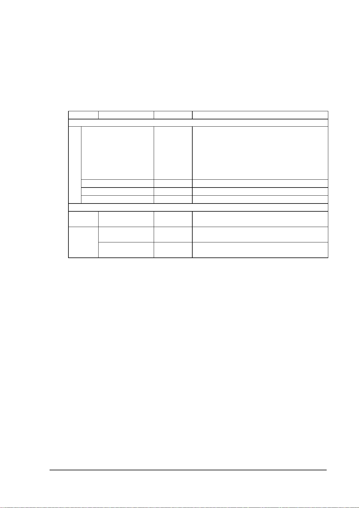
2.2.1 With Single I/O Box
RS-232C
PC
Fig.2.1 System configuration with single Satellite I/O Box
Hardware
Satellite I/O Box
RS-232C cable
IT-2000
PC
Table 2.2 Hardware and software configuration with single Satellite I/O Box
Upload/Download Utility FLINK of Windows 3.1 ver.
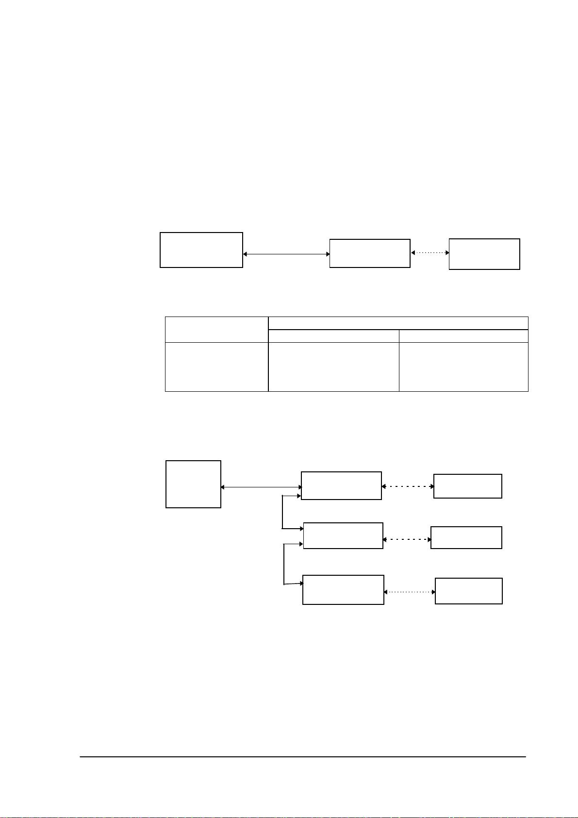
2.2.2 With Multiple I/O Boxes
RS-232C
PC
C-out
RS-422
C-in
Satellite I/O Box
Software
PC side IT-2000 side
Satellite I/O Box
Satellite I/O Box
IrDA
or FLINK of MD-DOS ver.
IrDA
IrDA
IT-2000
IT-2000
IT-2000
C-out
RS-422
Maximum 8 Satellite I/O Boxes can be connected.
Fig. 2.2 System configuration with multiple Satellite I/O Boxes
C-in
Satellite I/O Box
5
IrDA
IT-2000
Page 6
SoftwareHardware
PC side IT-2000 side
Satellite I/O Box
RS-232C cable
RS-422 cable
IT-2000
PC
Table 2.3 Hardware and software configuration with multiple Satellite I/O Boxes
Upload/Download Utility FLINK of Windows3.1 version or
FLINK of MS-DOS version
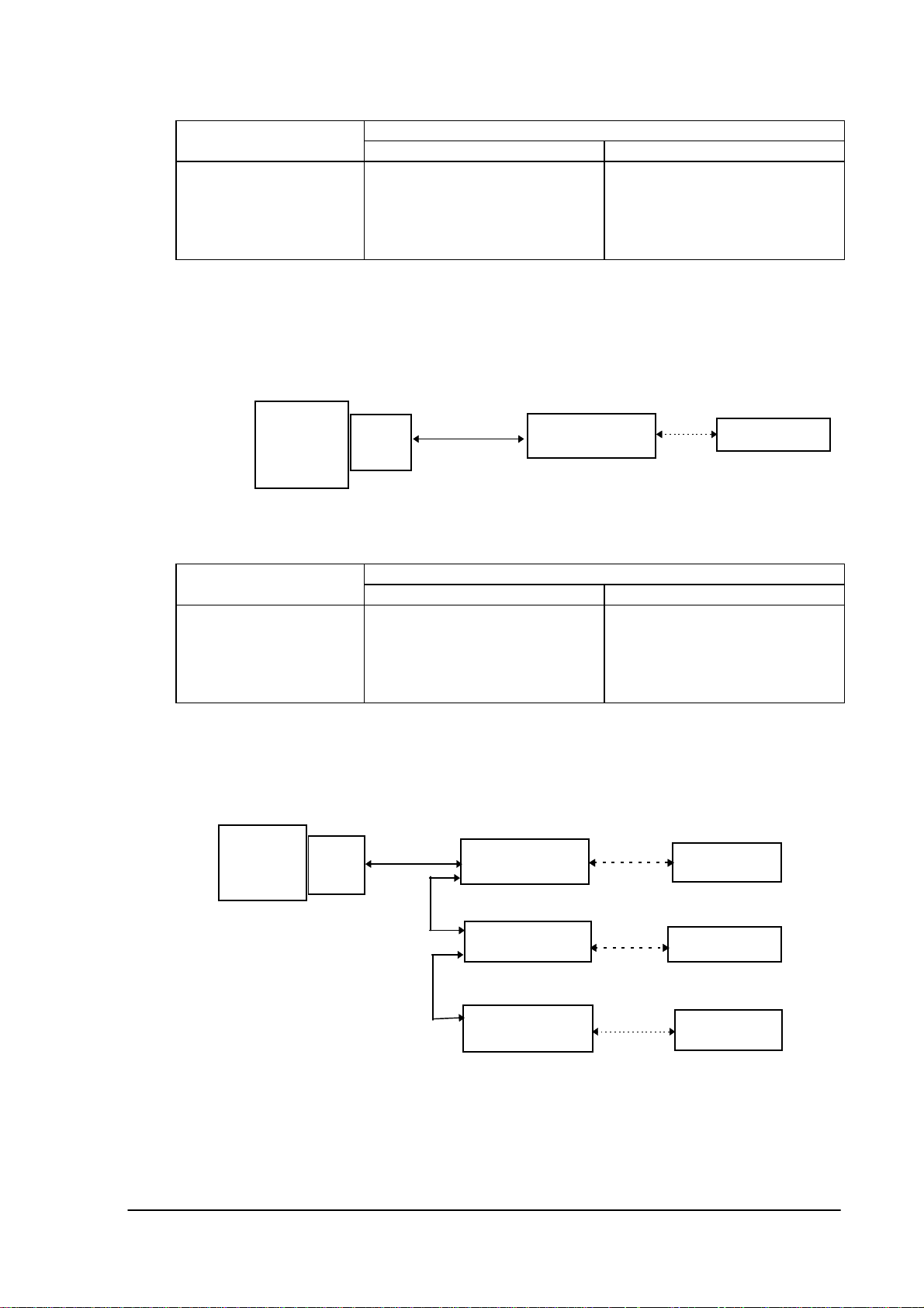
2.2.3 With Single Master I/O Box
SCSI
PC
Fig.2.3 System configuration with single Master I/O Box
Hardware
Master I/O Box
SCSI cable
SCSI Board
IT-2000
PC
Table 2.4 Hardware and software configuration with one Master I/O Box
SCSI
Board
PC side IT-2000 side
Upload/Download Utility FLINK of Windows3.1 ver. or
Master I/O Box
2.2.4 With Multiple Master I/O Boxes
SCSI
SCSI
Master I/O Box
C-out
C-in
Master I/O Box
PC
SCSI
Board
IrDA
Software
FLINK of MS-DOS ver.
IrDA
IrDA
IT-2000
IT-2000
IT-2000
C-out
SCSI
Maximum 7 Master I/O Boxes can be connected.
Fig. 2.4 System configuration with multiple Master I/O Boxes
C-in
Master I/O Box
6
IrDA
IT-2000
Page 7
SoftwareHardware
PC side IT-2000 side
Master I/O Box
SCSI cable
Upload/Download Utility FLINK of Windows3.1 ver. or
FLINK of MS-DOS ver.
IT-2000
PC
SCSI Board
Table 2.5 Hardware and software configuration with multiple Master I/O Boxes
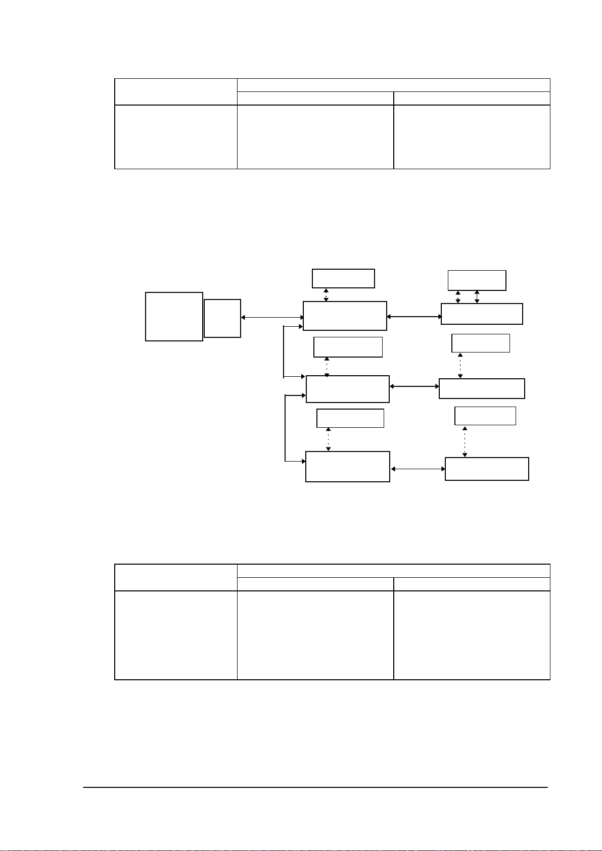
2.2.5 With Master and Satellite I/O Boxes
PC
SCSI
Board
SCSI
SCSI
IT-2000
IrDA
Master I/O Box
IT-2000
IrDA
Master I/O Box
IT-2000
RS-422
RS-422
IT-2000
Satellite I/O Box
IT-2000
IrDA
Satellite I/O Box
IT-2000
SCSI
IrDA
IrDA
RS-422
Master I/O Box
Satellite I/O Box
Maximum 7 Master I/O Boxes and 8 Satellite I/O Boxes can be connected.
Fig.2.5 System configuration with Master and Satellite I/O Boxes
Hardware
Software
PC side IT-2000 side
Satellite I/O Box
Master I/O Box
Upload/Download Utility FLINK of Windows3.1 version or
FLINK of MS-DOS version
SCSI cable
RS-422 cable
IT-2000
PC
SCSI Board
Table 2.6 Hardware and software configuration with Master and Satellite I/O Boxes
IrDA
7
Page 8
2.3 Installation Method
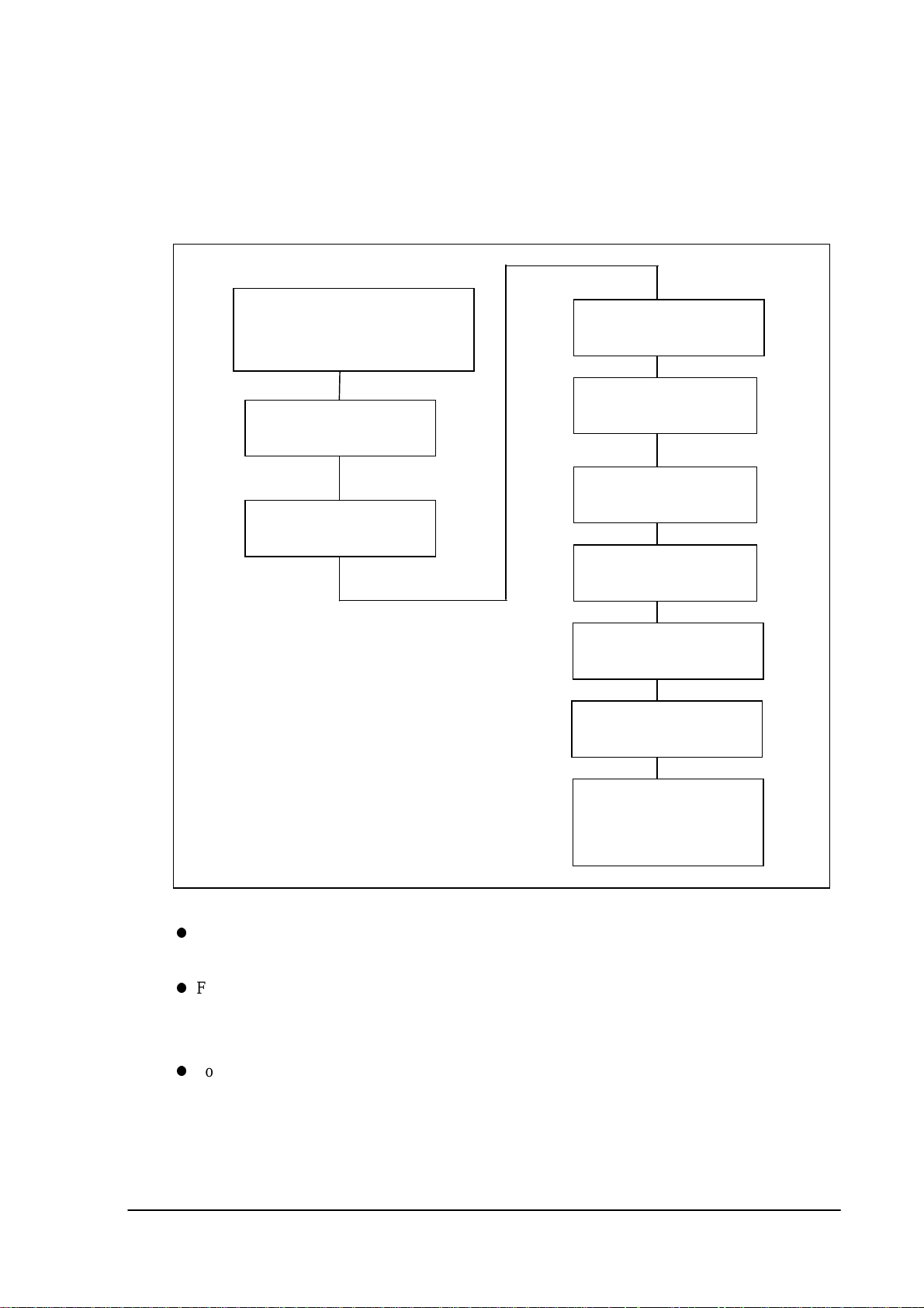
This section describes the installation and setup procedures that must be performed before I/O Box
and PC operations are started. The following diagram shows a flow of the setup procedure.
Fig.2.6 Installation flow of IT-2000
(If Master I/O Box is used)
Mount SCSI Board in the PC and
install the SCSI driver
Install Upload/Download
Utility in the PC.
Turn OFF the power of the
PC.
Set the DIP switch of I/O
Box.
Connect each cable between
I/O Boxes.
Connect cable between the
PC and I/O Box.
Connect AC adaptor for
each I/O Box.
Turn ON the power of all the
I/O Boxes.
Turn ON the power of the
PC.
Star up the
Upload/Download Utility
and set the environment.
Note:
For information about the installation procedure of the Upload/Download Utility refer to the
Upload/Download Utility Manual.
For information about the I/O Box setup refer to Chapter 2.3.1 “Setup of Satellite I/O Box”,
Chapter 2.3.2 “Setup of Master I/O Box”, and Chapter 2.3.3 “Setup of Satellite I/O Box to
Master I/O Box”.
For information about the setup of Upload/Download Utility environment refer to Chapter 2.3.4
“Setup of PC”.
8
Page 9
2.3.1 Setup of Satellite I/O Box
The following paragraphs explain how to set up the Satellite I/O Box and Master I/O Box to be
connected to the PC.
Note that the DIP switch settings of the Satellite I/O Box differ depending on the connection with
single Satellite I/O Box or multiple Satellite I/O Boxes.
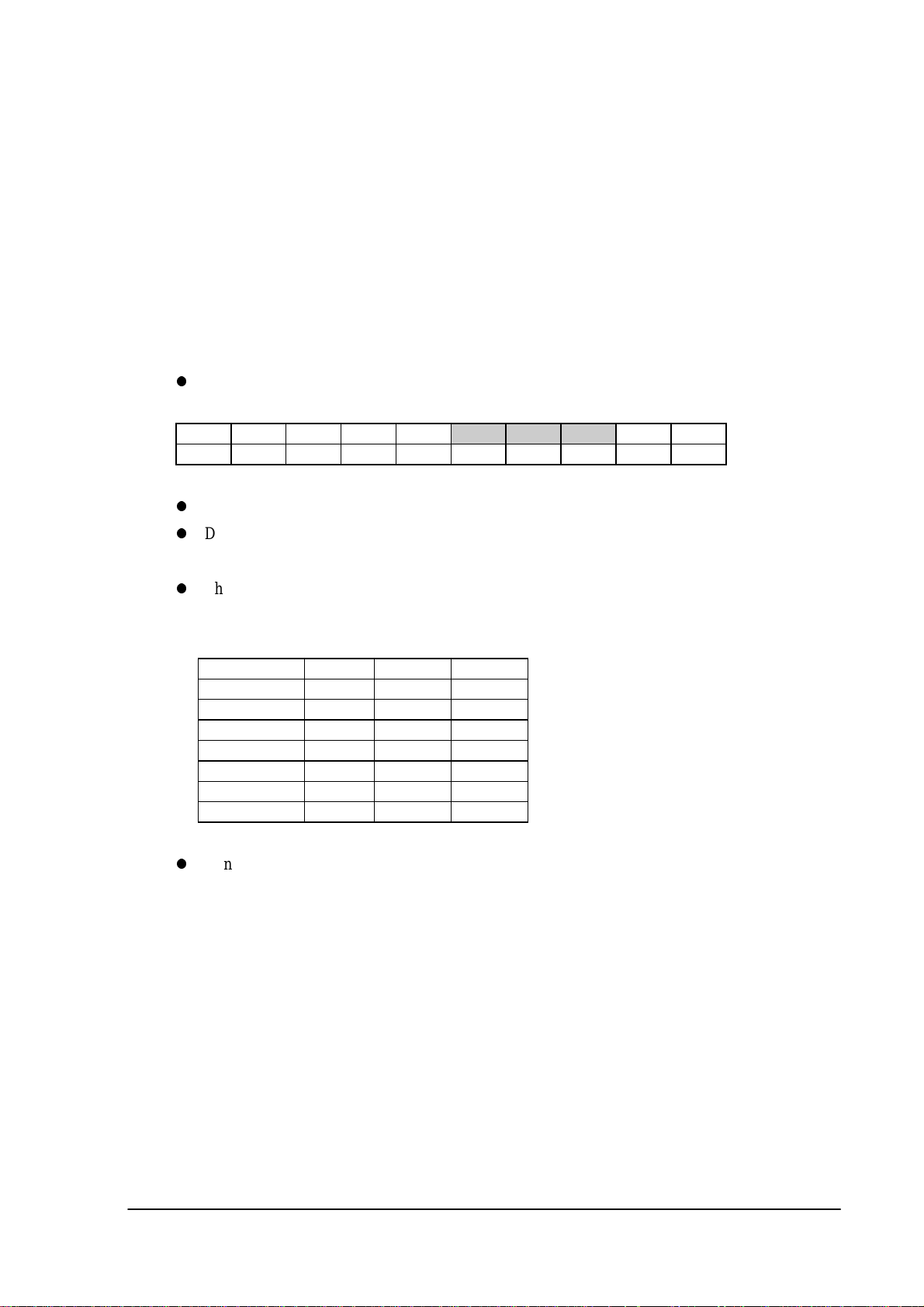
With single Satellite I/O Box
Make sure that the POWER switch of the I/O Box is set to OFF. Set the DIP switch at the rear
of the unit as follows:
12345
ON OFF OFF OFF ON OFF ON ON ON ON
Set the DIP switches nos. 1 to 5, 9, and 10 as shown above.
DIP switches nos 6, 7, and 8 are used to define the RS-232C baud rate of the I/O Box. It must
be consistent with the baud rate being set on the PC for RS-232C communication.
The above DIP setup example assumes that the RS-232C baud rate is 115200 bps. If modifying
678910
this setup, use the following table as a reference.
Baud Rate 6 7 8
2400 bps OFF OFF OFF
4800 bps ON OFF OFF
9600 bps OFF ON OFF
19200 bps ON ON OFF
38400 bps OFF OFF ON
57600 bps ON OFF ON
115200 bps OFF ON ON
Connect the I/O Box and the PC with a cross-type RS-232C cable.
With Multiple Satellite I/O Boxes
Note that the DIP switch settings of the Satellite I/O Box differ depending on the connection,
ex. Satellite I/O Box directly connected to the PC or Satellite I/O Box connected with other Satellite
I/O Boxes under daisy-chain.
9
Page 10
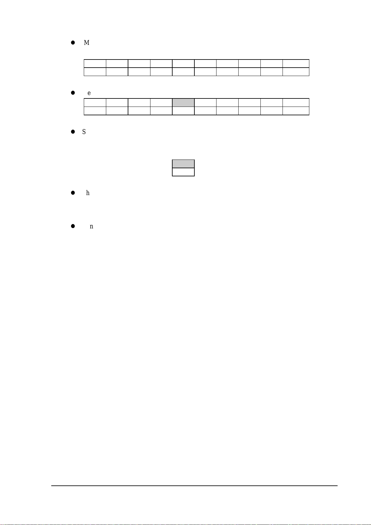
Make sure that the POWER switch of the I/O Box is set to OFF. Set the DIP switch of the
first I/O Box to be connected to the PC directly as follows.
12345678910
ON OFF OFF OFF OFF OFF ON ON ON ON
Set the DIP switch of other I/O Boxes to be connected under daisy-chain as follows.
12345678910
ON OFF OFF OFF ON OFF ON ON ON ON
Set DIP switch no. 5 of the last I/O Box to ON if the C-OUT terminal does not connect another
I/O Box (This is for the termination).
The above setup example assumes that the RS-232C baud rate is 115200 bps. If modifying this
setup, refer to the “With Single Satellite I/O Box” in the previous page.
5
ON
Connect the first I/O Box and the PC with a cross-type RS-232C cable.
Then connect the C-OUT terminal of the I/O Box connected to the PC to the C-IN terminal of
the other I/O Box via the RS-422 cable. Connect the rest of I/O Boxes so that the one with the
terminator setting is the last under daisy-chain.
10
Page 11

2.3.2 Setup of Master I/O Box
Note that the DIP switch settings of the Master I/O Box differ depending on whether the
system configuration is consisted of only single Master I/O Box or of multiple Master I/O Boxes that
are followed by Satellite I/O Boxes.
Make sure that the POWER switch of the I/O Box is set to OFF. Set the DIP switch at the rear
of the unit as follows:
12345
ON OFF OFF OFF ON OFF OFF OFF ON ON
Setup for the SCSI ID (DIP switches nos. 6, 7, and 8)
This SCSI ID must be different from that of other I/O Boxes or the PC.
Since generally the SCSI ID of the PC is set to 7, set the SCSI ID of the I/O Box to a number
between 0 and 6.
SCSI-ID 6 7 8
ID0 OFF OFF OFF
ID1 ON OFF OFF
ID2 OFF ON OFF
ID3 ONONOFF
ID4 OFF OFF ON
ID5 ON OFF ON
ID6 OFF ON ON
ID7 ONONON
678910
Setup termination for SCSI interface (no. 9)
Set DIP switch no.9 of the I/O Box, which is the farthest from the PC, to ON.
This setting is the same if only one I/O Box is connected.
SCSI termination setup
Termination ON
Non-termination OFF
Power setup for termination of SCSI interface (no.10)
If the SCSI board in the PC cannot supply power to the SCSI interface, set DIP switch no.10 of
the I/O Box, which is the nearest to the PC, to ON. However, DIP switch no. 10 is usually set
to OFF, since a general SCSI board can supply power to the SCSI interface.
9
11
Page 12

Power SCSI termination 10
Supplies power ON
Does not supply power OFF
Connect the first I/O Box and PC with the SCSI cable.
Then connect the SCSI connector of the I/O Box connected to the PC to the SCSI connector of
the other I/O Box via the SCSI cable. Connect the remaining I/O Boxes so that the one with the
terminator setting becomes to the last under daisy-chain connection.
Select a suitable cable that matches the shape of the connector on the PC side to connect the PC
and the first I/O Box.
2.3.3 Setup of Satellite I/O Box to Master I/O Box
Note that the DIP switch settings on Master I/O Box and on Satellite I/O Box differ.
DIP switch settings of the Master I/O Box
These settings are the same as stated in Chapter 2.3.2, "Setup of Master I/O Box" except
that the no.5 should be set to OFF.
12345678910
ON OFF OFF OFF OFF OFF OFF OFF ON OFF
DIP switch settings of the Satellite I/O Box
12345678910
ON OFF ON OFF OFF OFF ON ON ON ON
Set DIP switch no.5 to ON (i.e. setting as a terminator) if the C-OUT terminal is not
connected to another Satellite I/O Box to be daisy-chained.
5
ON
The above setup example assumes that the RS-232C baud rate is 115200 bps. If modifying this
setup, refer to Chapter 2.3.1, "Setup of Satellite I/O Box".
Connect the first Master I/O Box and PC with SCSI cable.
Then connect the C-OUT terminal of the Master I/O Box connected to the PC to the
C-IN terminal of the other Satellite I/O Box via the RS-422 cable. Connect the remaining I/O
Boxes so that the one with the terminator setting becomes the last under daisy-chain
connection.
12
Page 13

2.3.4 Setup of PC
Connection
If using the Satellite I/O Box, plug the connection cable into the COM port of the PC.
If using the Master I/O Box, plug the connection cable into the SCSI board of the PC.
Startup
First turn ON the power to each I/O Box, then turn ON the PC power to start up Windows95 and
start up the Upload/Download Utility.
Make sure that the Main Menu of the Upload/Download Utility appears.
Fig. 2.7 Main Menu screen of Upload/Download Utility
13
Page 14

Environment Setup
If the I/O Box to be connected to the PC is a Satellite I/O Box, select "RS-232C" from the
"Configure" menu of the Upload/Download Utility, then select "Settings" from the same menu.
Fig. 2.8 RS-232C Main Menu screen
In the COM PORT field select the COM port number in the PC to be used.
In the Baud Rate field select the communication speed (baud rate) of the RS-232C.
Parity, Stop bit, and Data bits values should be as shown in the above figure.
Confirm these setup values and click on the [OK] button.
Note:
Depending on the PC to be used, a baud rate that is too fast may hamper the communication.
If this is the case, employ a lower baud rate.
If the objective I/O Box to be connected to the PC is a Master I/O Box, select "SCSI" from the
"Configure" menu of the Upload/Download Utility, then select "Settings" from the same menu.
Fig. 2.9 SCSI Main Menu screen
14
Page 15

3. Operation Method
After connecting the necessary system devices and installing the software on the PC, perform file
upload/download with the following procedure. On this system each function will be executed if the
IT-2000, which has started up the FLINK Utility, is mounted on the I/O Box after the PC-side utility
was started up. Each function can also be executed by initiating the PC-side utility after mounting
the IT-2000, which has started up the FLINK Utility, on the I/O Box.
3.1 File Upload
Transfer files from the IT-2000 to the PC. There are two methods for specifying the files to be
uploaded: specifying files from the PC, and specifying files from the IT-2000.
3.1.1 Specifying Files from PC
Operation on PC
Start up the Upload/Download Utility on the PC and select "Command" from the "Execute"
menu to display the Command Screen.
Set the Command field to "Receive".
In the "File(s)" field specify the name of the objective file on the PC by its full path name.
In the "Destination Dir" field specify the directory by its full path name on the PC in which the
transmitted file is to be stored.
Fig. 3.1 Command Screen
15
Page 16

Set any "Options" item, if necessary.
Set the "Mode" option, if necessary.
Click on the [OK] button.
If preparation has been completed on the IT-2000 side, the progress bar will be displayed and file
uploading will begin.
If a communication anomaly occurs, an error message will be displayed and communication will be
terminated.
Operation on IT-2000
Start up MS-DOS.
Start up FLINK without adding parameters.
"Wait..." is displayed on the IT-2000 screen and the idle mode is set.
FLINK.DLL of Windows 3.1 version
Start up Windows3.1.
Start up FLINK without adding parameters.
DoFLINK ( argc, argv)
argc = 1;
argv[ ]= { "fl" }
"Wait..." is displayed on the IT-2000 screen and the idle mode is set.
If preparation has been completed on the PC side, the progress bar will be displayed and file
uploading will begin.
If a communication anomaly occurs, an error message will be displayed and communication will be
terminated.
16
Page 17

3.1.2 Specifying Files from IT-2000
Operation on PC
Start up the Upload/Download Utility on the PC and select "Link Manager Start" from the
"Execute" menu.
Fig. 3.2 Screen displayed after "Link Manager Start"
If the preparation has been completed on the IT-2000 side, the progress bar will be displayed and
the file upload will begin. If a communication anomaly occurs, an error message will be displayed
and communication will be terminated.
Operation on IT-2000
FLINK.EXE of MS-DOS version
Start up MS-DOS.
Start up FLINK with the send mode option.
FLINK /S D:FILE C:
This transfers D:FILE from the IT-2000 to C: on the PC.
If preparation has been completed on the PC side, the progress bar will be displayed and file
uploading will begin. If a communication anomaly occurs, an error message will be displayed and
communication will be terminated.
17
Page 18

FLINK.DLL of Windows 3.1 version
Start up Windows 3.1.
Start up FLINK with the appropriate parameters.
DoFLINK ( argc, argv )
argc = 4;
argv[ ]= { "fl" , "/s", "D:FILE", "C:yy" }
This transfers D:FILE from the IT-2000 to C:yy on the PC.
If the preparation has been completed on the PC side, the progress bar will be displayed and file
uploading will begin. If a communication anomaly occurs, an error message will be displayed and
communication will be terminated.
18
Page 19

3.2 File Download
Transfer files from the PC to the IT-2000.
There are two methods for specifying the files to be downloaded: specifying files from the PC, and
specifying files from the IT-2000.
3.2.1 Specifying Files from PC
Operation on PC
Start up the Upload/Download Utility on the PC and select "Command" from the "Execute"
menu to display the Command Screen.
Set the Command field to "Send".
In the "File(s)" field specify the name of the objective file on the PC by its full path name.
In the "Destination Dir" field specify the directory by its full path name on the IT-2000 in
which the received file is to be stored.
Fig. 3.3 Command Screen
Set any "Options" item, if necessary.
Set "Mode" option, if necessary.
Click on the [OK] button.
If the preparation has been completed on the IT-2000 side, the progress bar will be displayed and
file downloading will begin. If a communication anomaly occurs, an error message will be displayed
and communication will be terminated.
19
Page 20

Operation on IT-2000
FLINK.EXE of MS-DOS version
Start up MS-DOS.
Start up FLINK without adding any parameters.
"Wait..." is displayed on the IT-2000 screen and the idle mode is set.
FLINK.DLL of Windows 3.1 version
Start up Windows 3.1.
Start up FLINK without adding any parameters.
DoFLINK ( argc, argv)
argc = 1;
argv[ ]= { "fl" }
"Wait..." is displayed on the IT-2000 screen and the idle mode is set.
If the preparation has been completed on the PC side, the progress bar will be displayed and file
downloading will begin. If a communication anomaly occurs, an error message will be displayed and
communication will be terminated.
20
Page 21

3.2.2 Specifying Files from IT-2000
Operation on PC
Start up the Upload/Download Utility on the PC and select "Link Manager Start" from the
"Execute" menu.
Fig. 3.4 Screen displayed after "Link Manager Start"
If the preparation has been completed on the IT-2000 side, the progress bar will be displayed and
file downloading will begin. If a communication anomaly occurs, an error message will be displayed
and communication will be terminated.
Operation on IT-2000
FLINK.EXE of MS-DOS version
Start up MS-DOS.
Start up FLINK with the receive mode option.
FLINK /R C:FILE D:
This transfers C:FILE from the PC to D: on the IT-2000.
21
Page 22

FLINK.DLL of Windows 3.1 version
Start up Windows3.1.
Start up FLINK with the receive mode option.
DoFLINK ( argc, argv )
argc = 4;
argv[ ]= { "fl" , "/r", "C:FILE", "D:yyy" }
This transfers C:FILE from the PC to D:yyy on the IT-2000.
If the preparation has been completed on the PC side, the progress bar will be displayed and file
downloading will begin. If a communication anomaly occurs, an error message will be displayed and
communication will be terminated.
22
Page 23

4. Error Codes and Error Messages
Any termination codes and error information generated by the PC will be recorded in the error log
file on the PC.
This error log file will be created according to the file name specified by the DEVICE.INI file
(configuration file), and each new log entry will be appended to the file.
This error log file cannot be automatically deleted. Therefore, it is recommended to check the
contents when required and delete the file.
If an error occurs on the PC side, the corresponding error message will appear on the PC's display.
Since error messages are displayed for each I/O Box, a maximum of eight error messages can be
displayed at one time. If an error occurs on the IT-2000 side, the corresponding error message will
appear on the LCD of the IT-2000.
Session
No.
0 6- 9-1997 17-44-46 0 1 Undefined function code
0 6- 9-1997 18- 1-24 0 5 Communication error
0 8- 9-1997 11-53-29 4 5 Command timeout error
Table 4.1 Example error log file
For information about the error codes and error messages and their remedies, refer to Table 4.2
"Error Codes and Error Messages".
When confirming the contents of the error log file, use a commercial editor. No dedicated editor is
supplied by Casio.
Date Time
Error Code
Detail Category
Error Message
23
Page 24

Error Code Error Message Description Remedy
Categ. Detai
0x00 0x00 NormalEnding
0xDC 0x00 ADriveFormatNotice
0xF5 0x00 ZDriveFormatNotice
0xF8 0x00 BreakKeyInterruptEndingNotice
0x01 0x00 UndefineFunctionCode
0x01 0x01 UndefineSubFunctionCode
0x01 0x02 NotExecuteCommand
0x01 0x03 CheckSumError
0x01 0x04 CommandSequenceError
0x01 0x05 SequenceNumberError
0x01 0x06 OtherProtocolError
0x01 0x07 ParameterError
Normal end. Format notification of drive A Format notification of drive Z Notification of abortion by user. Protocol error (function code) See note 1.
Protocol error (sub-function code) See note 1.
Command cannot be executed. See note 1.
Check-sum error See note 1.
Command sequence error. See note 1.
Sequence number error. See note 1.
Protocol is illegal. See note 1.
Parameter error. Check if the operation is
correct.
0x01 0x08 TimeoutError
0x01 0x10 DataLengthError
0x01 0x12 ProtocolVersionDifferenceError
Timeout error. See note 1.
Protocol error (DATA LEN). See note 1.
Protocol version does not match. Use the latest version of
Upload/Download Utility.
0x01 0x13 MemoryAllocationError
0x01 0x15 FileSizeError
0x01 0x15 DateError
0x01 0x16 TimeError
0x01 0x17 FileAttributeError
0x01 0x18 OverwriteOptionError
0x01 0x19 EOFFlagError
0x02 0x02 FileNotFound
0x02 0x03 PathNotFound
0x02 0x0B InvalidFormat
0x02 0x0F InvalidDiskDrive
0x02 0x10 DeleteRequestisCurrentDirectory
Memory cannot be allocated. Close other applications first.
Protocol error (file size). See note 1.
Protocol error (date). See note 1.
Protocol error (time). See note 1.
Protocol error (attribution) See note 1.
Protocol error (Forced over write). See note 1.
Protocol error (EOF). See note 1.
File cannot be found. See note 2.
Path cannot be found. See note 2.
Invalid formatting. See note 2.
Invalid disk. See note 2.
Delete request is specified to current
See note 2.
directory.
0x02 0x11 NotSameDisk
0x02 0x12 FileNothing
0x03 0x13 WriteProtectError
0x03 0x14 UnknownUnit
0x03 0x15 DriveNotReady
0x03 0x17 DataError
0x03 0x19 SeekError
0x03 0x1A UnknownDiskFormat
0x03 0x1B SectorNotFound
0x03 0x1D WriteError
0x03 0x1E ReadError
0x03 0x20 FileShareError
0x03 0x21 FileLockError
0x03 0x22 InvalidDiskChanged
0x03 0x23 FCBFull
0x03 0x53 FatalError
Disk is not the same. See note 2.
File cannot be found. See note 2.
Write protect error. See note 2.
Undefined unit. See note 2.
Drive is not ready. See note 2.
Data error. See note 2.
Seek error. See note 2.
Disk is not formatted. See note 2.
Sector cannot be found. See note 2.
Write error. See note 2.
Read error. See note 2.
Specified file is already opened. See note 2.
File lock error. See note 2.
Invalid disk exchange. See note 2.
FCB is full. See note 2.
Fatal error. See note 2.
24
Page 25

Error Code
categDetai
0x040x00ReadOnlyFileAccessError Write is specified to read-only-file. Change the file attribution for
Er
ror
0x050x00CommunicationError Communication error. See note 1.
0x050x03SpawnError Spawn error. See note 1.
0x050x04CommandTimoutError Command timeout error. See note 1.
0x050x05ErrorOpeningErrorLogFile Fail to open log file. Check if the path name of log file
0x050x06OptionError Option error. Check if the selection of operation
0x050x07StartupError Startup error. Check if other application is using
0x050x08OpenError Open error. See note 1.
0x050x09ListenError Listen error. See note 1.
0x050x0AAcceptError Accept error. See note 1.
0x050x0BNotEnoughMemoryToExecuteProcessMemory is not enough. Close other applications first.
0x050x0CArgumentListTooLargeForTheProcessProcess is too long. See note 1.
0x050x0DInvalidModeForTheProcess Child-process ends illegally. Check the operation method.
0x050x0EProcessTerminatedNormally Child-process ends normally. Normal end.
0x050x0FNoiseError Communication noise error. See note 1.
Error Message Description Remedy
write.
is correct.
is correct.
the COM port.
Table 4.2 Error codes and error messages
Note:
1. First make sure the connection of each option is complete and each component is
powered properly. Next, restart the system and execute the process again. If the same error
occurs again, reduce the baud rate before retrying. If normal operation cannot be achieved even
after making the above adjustments, contact your nearest support/technical center.
2. The file could not be properly accessed. Check if the file can be properly accessed or if the
disk is full.
25
Page 26

5. Q and A
Common to Satellite and Master I/O Boxes
Q1
It seems that it takes a rather long time for communication to start, doesn't it?
A1
Communication between the IT-2000 and Satellite/Master I/O Box is performed according to IrDA
protocol. Generally, the IrDA protocol requires 2 to 3 seconds until communication between the
PC and IT-2000 is established. This period of time is required for each IT-2000 terminal.
It may take more than 10 seconds for communication to start if multiple Satellite and Master I/O
Boxes are connected under daisy-chain.
Q2
Which IrDA standard is used for communication between the IT-2000 and Satellite/Master I/O
Box ?
A2
IrDA 1.0 is used for communication between the Satellite I/O Box and IT-2000, and IrDA 1.1 is
used for communication between the Master I/O Box and IT-2000.
Q3
If multiple Satellite I/O Boxes and Master I/O Boxes are to be chain-connected, is there an
order in which they must be connected?
A3
They do not have to be connected in any particular order, since, with the IrDA protocol, the next
terminal to be connected is randomly selected each time communication has been completed up to
the current terminal.
Satellite I/O Box
Q1
What happens if the power to a Satellite I/O Box connected in the middle of the daisy-chain is
turned OFF ?
A1
Communication can only be performed between the PC and the Satellite I/O Boxes, which are
located in the nearer positions to the PC delimited by the Satellite I/O Box having been powered off.
26
Page 27

Q2
If the Windows3.1 version of FLINK is used, the baud rate setup cannot be modified by changing
the DIP switch setting for the RS-232C communication speed on the Satellite I/O Box. Why?
A2
To modify the RS-232C communication speed with the Windows3.1 version of FLINK, it must
be started up with the following option. Otherwise, the default value of 9600 bps is automatically
used.
Option:
The communication speed can be determined according to the DIP switch setting of the Satellite I/O
Box only if the MS-DOS version of FLINK is used.
Q3
If an attempt is made to execute the Upload/Download Utility, a startup error appeared. Why?
A3
This startup error occurs if the COM port is being used by another application.
In addition, if an application that uses the COM port is executed from the DOS window, the COM
port is not accessible from other applications until the DOS window has been closed.
Q4
If multiple Satellite I/O Boxes are connected under daisy-chain, can each IT-2000 terminal
/L {baud rate parameter,2,,,,,,, }
9600 for 9600 bps
384K for 38400 bps
115K for 115200 bps
independently use either the MS-DOS version of FLINK or the Windows3.1 version of FLINK ?
A4
This is not permitted. All IT-2000 terminals must use the same version.
Master I/O Box
Q1
If the Master I/O Box is connected, the SCSI check box in LMWIN cannot be selected. Why?
A1
First turn ON the power to the Master I/O Box, then turn ON the power to the PC. If this order is
reversed, the I/O Box cannot be recognized by the system. Or, SCSI IDs may be duplicated. Check
this.
27
Page 28

Q2
What is the maximum baud rate if the Satellite I/O Boxes are connected under daisy-chain so they
follow each Master I/O Box ?
A2
In this case the physical Master I/O Box-to-Satellite I/O Box speed is 115200 bps max.
Q3
Can I update the version of Master I/O Box firmware ?
A3
Yes, by using the dedicated download tool and a SCSI cable. Your nearest support/technical center
will inform you if it is necessary.
Q4
What happens if the power to a middle Master I/O Box which is connected to the PC is turned
OFF ?
A4
The Master I/O Box that is turned OFF and all Satellite I/O Boxes that are connected to that
Master I/O Box are communication-disabled. Communication with Master I/O Boxes, other than
with that which is turned OFF, is permitted. To make the Master I/O Box available again, turn ON
that Master I/O Box first, then restart the PC.
Q5
If an attempt was made to execute the Upload/Download Utility, a startup error appeared. Why?
A5
A startup error occurs if the SCSI cable is not properly plugged in or if the power to all the
Master I/O Boxes is not on.
Q6
If multiple Master I/O Boxes are connected, can each IT-2000 terminal independently use either
the MS-DOS version of FLINK or the Windows3.1 version of FLINK ?
A6
This is not permitted. A timeout error will occur because of a timing lag between the MS-DOS
version of FLINK and the Windows3.1 version of FLINK.
28
Page 29

6. Reference Manuals
Besides this IT-2000 I/O Box Installation Manual, the following manuals are available for the
IT-2000 system as application program development manual.
IT-2000 Upload/Download Utility Manual
IT-2000 Technical Reference Manual
IT-2000 Hardware Manual
29
Page 30

7. List of SCSI Boards and SCSI Cables
The listed SCSI Boards and Cables below have been assessed for the operability with the IT-2000.
Thus, they are recommended for use with the IT-2000.
Manufacturer Model
SCSI Board
Adaptec AHA1540CP
Adaptec AHA2940AU
Adaptec AHA1510B
Adaptec AHA1542CF
SCSI Cable
Casio SB-751HF
Casio SB-752HH
Casio SB-753HP
Table 7.1 SCSI Boards and SCSI Cables
30
Page 31

Appendix Installation Method of Upload/Download Utility
Installation
The Upload/Download Utility software consists of the following software components:
File name Remark
LMWIN32.EXE Execution module of the Upload/Download Utility (GUI mode)
driver32.dll RS-232C driver
hfc32.dll Command analysis driver
Iman32.dll Connection monitor driver
scsidrv.dll SCSI connection driver
tcpip.dll Spare file for TCP IP connection
LMWIN.INI Execution initial conditions setup file
DEVICE.INI Configuration file
Other Other files/Help file required for the Upload/Download Utility
The above software components are supplied as a complete package. All files and libraries necessary
for installation can be generated from the “ Setup.exe “ program.
Syntax of the Installer Command
Start up “ Setup.exe ” from the setup directory in the supplied FD.
setup
>
31
 Loading...