

Page 1
ADMINISTRATION
GUIDE
Cisco Small Business
ISA500 Series Integrated Security Appliances
(ISA550, ISA550W, ISA570, ISA570W)
Page 2

© 2013 Cisco Systems, Inc. All rights reserved. 78-20776-03
Cisco and the Cisco logo are trademarks or registered trademarks of Cisco and/or its affiliates in the U.S. and other countries. To view a list of Cisco trademarks,
go to this URL: www.cisco.com/go/trademarks. Third-party trademarks mentioned are the property of their respective owners. The use of the word partner
does not imply a partnership relationship between Cisco and any other company. (1110R)
Page 3

Federal Communication Commission Interference Statement
(For ISA570 and ISA570W)
This equipment has been tested and found to comply with the limits for a Class A digital
device, pursuant to Part 15 of the FCC Rules. These limits are designed to provide
reasonable protection against harmful interference when the equipment is operated in a
commercial environment. This equipment generates, uses, and can radiate radio frequency
energy and, if not installed and used in accordance with the instruction manual, may cause
harmful interference to radio communications. Operation of this equipment in a residential
area is likely to cause harmful interference in which case the user will be required to correct
the interference at his own expense.
(For ISA550 and ISA550W)
This equipment has been tested and found to comply with the limits for a Class B digital
device, pursuant to Part 15 of the FCC Rules. These limits are designed to provide
reasonable protection against harmful interference in a residential installation. This
equipment generates, uses and can radiate radio frequency energy and, if not installed and
used in accordance with the instructions, may cause harmful interference to radio
communications. However, there is no guarantee that interference will not occur in a
particular installation. If this equipment does cause harmful interference to radio or television
reception, which can be determined by turning the equipment off and on, the user is
encouraged to try to correct the interference by one of the following measures:
• Reorient or relocate the receiving antenna.
• Increase the separation between the equipment and receiver.
• Connect the equipment into an outlet on a circuit different from that to which the
receiver is connected.
• Consult the dealer or an experienced radio/TV technician for help.
FCC Caution: Any changes or modifications not expressly approved by the party responsible
for compliance could void the user's authority to operate this equipment.
This device complies with Part 15 of the FCC Rules. Operation is subject to the following two
conditions: (1) This device may not cause harmful interference, and (2) this device must
accept any interference received, including interference that may cause undesired operation.
IMPORTANT NOTE:
FCC Radiation Exposure Statement: (For ISA550W and ISA570W)
This equipment complies with FCC radiation exposure limits set forth for an uncontrolled
environment. This equipment should be installed and operated with minimum distance 20cm
between the radiator & your body.
This transmitter must not be co-located or operating in conjunction with any other antenna or
transmitter.
Page 4

The availability of some specific channels and/or operational frequency bands are country
dependent and are firmware programmed at the factory to match the intended destination.
The firmware setting is not accessible by the end user.
Industry Canada statement:
This device complies with RSS-210 of the Industry Canada Rules. Operation is subject to the
following two conditions: (1) This device may not cause harmful interference, and (2) this
device must accept any interference received, including interference that may cause
undesired operation.
Ce dispositif est conforme à la norme CNR-210 d'Industrie Canada applicable aux appareils
radio exempts de licence. Son fonctionnement est sujet aux deux conditions suivantes: (1) le
dispositif ne doit pas produire de brouillage préjudiciable, et (2) ce dispositif doit accepter
tout brouillage reçu, y compris un brouillage susceptible de provoquer un fonctionnement
indésirable.
IMPORTANT NOTE:
Canada Radiation Exposure Statement: (For ISA550W and ISA570W)
This equipment complies with Canada radiation exposure limits set forth for an uncontrolled
environment. This equipment should be installed and operated with minimum distance 20 cm
between the radiator and your body.
NOTE IMPORTANTE: (Pour l'utilisation de dispositifs mobiles)
Déclaration d'exposition aux radiations:
Cet équipement est conforme aux limites d'exposition aux rayonnements IC établies pour un
environnement non contrôlé. Cet équipement doit être installé et utilisé avec un minimum de
20 cm de distance entre la source de rayonnement et votre corps.
This device has been designed to operate with an antenna having a maximum gain of 1.8 dBi.
Antenna having a higher gain is strictly prohibited per regulations of Industry Canada. The
required antenna impedance is 50 ohms.
Under Industry Canada regulations, this radio transmitter may only operate using an antenna
of a type and maximum (or lesser) gain approved for the transmitter by Industry Canada. To
reduce potential radio interference to other users, the antenna type and its gain should be so
chosen that the equivalent isotropically radiated power (e.i.r.p.) is not more than that
necessary for successful communication.
(Le manuel d'utilisation de dispositifs émetteurs équipés d'antennes amovibles doit contenir
les informations suivantes dans un endroit bien en vue:)
Ce dispositif a été conçu pour fonctionner avec une antenne ayant un gain maximal de 1.8
dBi. Une antenne à gain plus élevé est strictement interdite par les règlements d'Industrie
Canada. L'impédance d'antenne requise est de 50 ohms.
Page 5

Conformément à la réglementation d'Industrie Canada, le présent émetteur radio
peutfonctionner avec une antenne d'un type et d'un gain maximal (ou inférieur) approuvé
pourl'émetteur par Industrie Canada. Dans le but de réduire les risques de brouillage
radioélectriqueà l'intention des autres utilisateurs, il faut choisir le type d'antenne et son gain
de sorte que lapuissance isotrope rayonnée équivalente (p.i.r.e.) ne dépasse pas l'intensité
nécessaire àl'établissement d'une communication satisfaisante.
UL/CB
Rack Mount Instructions - The following or similar rack-mount instructions are included with
the installation instructions:
A) Elevated Operating Ambient - If installed in a closed or multi-unit rack assembly, the
operating ambient temperature of the rack environment may be greater than room ambient.
Therefore, consideration should be given to installing the equipment in an environment
compatible with the maximum ambient temperature (Tma) 40 degree C specified by the
manufacturer.
B) Reduced Air Flow - Installation of the equipment in a rack should be such that the amount
of air flow required for safe operation of the equipment is not compromised.
C) Mechanical Loading - Mounting of the equipment in the rack should be such that a
hazardous condition is not achieved due to uneven mechanical loading.
D) Circuit Overloading - Consideration should be given to the connection of the equipment to
the supply circuit and the effect that overloading of the circuits might have on overcurrent
protection and supply wiring. Appropriate consideration of equipment nameplate ratings
should be used when addressing this concern.
Page 6

Contents
Chapter 1: Getting Started 19
Introduction 20
Product Overview 21
Front Panel 21
Back Panel 23
Getting Started with the Configuration Utility 25
Logging in to the Configuration Utility 26
Navigating Through the Configuration Utility 27
Using the Help System 28
Configuration Utility Icons 28
Factory Default Settings 30
Default Settings of Key Features 30
Restoring the Factory Default Settings 31
Performing Basic Configuration Tasks 32
Changing the Default Administrator Password 32
Upgrading your Firmware After your First Login 33
Backing Up Your Configuration 34
Chapter 2: Configuration Wizards 35
Using the Setup Wizard for the Initial Configuration 36
Starting the Setup Wizard 37
Configuring Cisco.com Account Credentials 37
Enabling Firmware Upgrade 38
Validating Security License 39
Enabling Bonjour and CDP Discovery Protocols 39
Configuring Remote Administration 40
Configuring Physical Ports 41
Configuring the Primary WAN 42
Configuring the Secondary WAN 42
Configuring WAN Redundancy 42
Configuring Default LAN Settings 43
Configuring DMZ 44
Cisco ISA500 Series Integrated Security Appliances Administration Guide 6
Page 7

Contents
Configuring DMZ Services 45
Configuring Wireless Radio Settings 47
Configuring Intranet WLAN Access 48
Configure Security Services 49
Viewing Configuration Summary 50
Using the Dual WAN Wizard to Configure WAN Redundancy Settings 51
Starting the Dual WAN Wizard 51
Configuring a Configurable Port as a Secondary WAN Port 51
Configuring the Primary WAN 52
Configuring the Secondary WAN 52
Configuring WAN Redundancy 52
Configuring Network Failure Detection 53
Viewing Configuration Summary 54
Using the Remote Access VPN Wizard 54
Using the Remote Access VPN Wizard for IPsec Remote Access 54
Starting the Remote Access VPN Wizard 55
Configuring IPsec Remote Access Group Policy 55
Configuring WAN Settings 56
Configuring Operation Mode 56
Configuring Access Control Settings 57
Configuring DNS and WINS Settings 57
Configuring Backup Servers 58
Configuring Split Tunneling 58
Viewing Group Policy Summary 58
Configuring IPsec Remote Access User Groups 59
Viewing IPsec Remote Access Summary 59
Using Remote Access VPN Wizard for SSL Remote Access 60
Starting the Remote Access VPN Wizard with SSL Remote Access 60
Configuring SSL VPN Gateway 60
Configuring SSL VPN Group Policy 62
Configuring SSL VPN User Groups 65
Viewing SSL VPN Summary 66
Using the Site-to-Site VPN Wizard to Configure Site-to-Site VPN 66
Starting the Site-to-Site VPN Wizard 67
Configuring VPN Peer Settings 67
Configuring IKE Policies 68
Cisco ISA500 Series Integrated Security Appliances Administration Guide 7
Page 8

Configuring Transform Policies 69
Configuring Local and Remote Networks 70
Viewing Configuration Summary 70
Using the DMZ Wizard to Configure DMZ Settings 71
Starting the DMZ Wizard 71
Configuring DDNS Profiles 71
Configuring DMZ Network 72
Configuring DMZ Services 74
Viewing Configuration Summary 76
Using the Wireless Wizard (for ISA550W and ISA570W only) 76
Starting the Wireless Wizard 76
Configuring Wireless Radio Settings 76
Configuring Wireless Connectivity Types 77
Contents
Specify Wireless Connectivity Settings for All Enabled SSIDs 78
Viewing Configuration Summary 78
Configuring the SSID for Intranet WLAN Access 78
Configuring the SSID for Guest WLAN Access 80
Chapter 3: Status 84
Device Status Dashboard 84
Network Status 88
Status Summary 88
Traffic Statistics 91
Usage Reports 92
WAN Bandwidth Reports 94
ARP Table 95
DHCP Bindings 95
STP Status 96
CDP Neighbor 98
Wireless Status (for ISA550W and ISA570W only) 99
Wireless Status 99
Client Status 100
Cisco ISA500 Series Integrated Security Appliances Administration Guide 8
Page 9

NAT Status 100
VPN Status 101
IPsec VPN Status 101
SSL VPN Status 103
Active User Sessions 105
Security Services Reports 106
Web Security Report 106
Anti-Virus Report 107
Email Security Report 108
Network Reputation Report 109
IPS Report 110
Application Control Report 111
System Status 112
Contents
Processes 112
Resource Utilization 113
Chapter 4: Networking 115
Viewing Network Status 116
Configuring IPv4 or IPv6 Routing 116
Managing Ports 116
Viewing Status of Physical Interfaces 117
Configuring Physical Ports 118
Configuring Port Mirroring 119
Configuring Port-Based (802.1x) Access Control 120
Configuring the WAN 122
Configuring WAN Settings for Your Internet Connection 122
Configuring WAN Redundancy 130
Dual WAN Settings 130
Configuring Link Failover Detection 132
Load Balancing with Policy-Based Routing Configuration Example 133
Configuring Dynamic DNS 134
Measuring and Limiting Traffic with the Traffic Meter 135
Configuring a VLAN 137
Cisco ISA500 Series Integrated Security Appliances Administration Guide 9
Page 10

Contents
Configuring DMZ 141
Configuring Zones 146
Security Levels for Zones 146
Predefined Zones 147
Configuring Zones 147
Configuring DHCP Reserved IPs 149
Configuring Routing 149
Viewing the Routing Table 150
Configuring Routing Mode 150
Configuring Static Routing 151
Configuring Dynamic Routing - RIP 152
Configuring Policy-Based Routing 153
Configuring Quality of Service 155
General QoS Settings 155
Configuring WAN QoS 156
Managing WAN Bandwidth for Upstream Traffic 156
Configuring WAN Queue Settings 157
Configuring Traffic Selectors 158
Configuring WAN QoS Policy Profiles 160
Configuring WAN QoS Class Rules 160
Mapping WAN QoS Policy Profiles to WAN Interfaces 161
WAN QoS Configuration Example 162
Configure WAN QoS for Voice Traffic from LAN to WAN 164
Configuring WAN QoS for Voice Traffic from WAN to LAN 165
Configuring LAN QoS 166
Configuring LAN Queue Settings 167
Configuring LAN QoS Classification Methods 167
Mapping CoS to LAN Queue 168
Mapping DSCP to LAN Queue 168
Configuring Default CoS 169
Configuring Wireless QoS 169
Default Wireless QoS Settings 169
Configuring Wireless QoS Classification Methods 170
Mapping CoS to Wireless Queue 171
Mapping DSCP to Wireless Queue 171
Understanding DSCP Values 171
Cisco ISA500 Series Integrated Security Appliances Administration Guide 10
Page 11

Configuring IGMP 172
Configuring VRRP 173
Address Management 175
Configuring Addresses 175
Configuring Address Groups 176
Service Management 177
Configuring Services 177
Configuring Service Groups 178
Configuring Captive Portal 179
Requirements 179
Before You Begin 180
VLAN Setup 180
Wireless Setup 181
Contents
User Authentication 181
Configuring a Captive Portal 181
Troubleshooting 185
Using External Web-Hosted CGI Scripts 186
CGI Source Code Example: No Authentication and Accept Button 195
Related Information 204
Chapter 5: Wireless (for ISA550W and ISA570W only) 206
Viewing Wireless Status 207
Viewing Wireless Statistics 207
Viewing Wireless Client Status 208
Configuring the Basic Settings 208
Configuring SSID Profiles 210
Configuring Wireless Security 211
Controlling Wireless Access Based on MAC Addresses 217
Mapping the SSID to VLAN 218
Configuring SSID Schedule 218
Configuring Wi-Fi Protected Setup 219
Configuring Captive Portal 221
Cisco ISA500 Series Integrated Security Appliances Administration Guide 11
Page 12

Requirements 222
Before You Begin 222
VLAN Setup 222
Wireless Setup 223
User Authentication 223
Configuring a Captive Portal 223
Troubleshooting 227
Using External Web-Hosted CGI Scripts 228
CGI Source Code Example: No Authentication and Accept Button 237
Related Information 246
Configuring Wireless Rogue AP Detection 247
Advanced Radio Settings 248
Contents
Chapter 6: Firewall 251
Configuring Firewall Rules to Control Inbound and Outbound Traffic 252
About Security Zones 252
Default Firewall Settings 254
Priorities of Firewall Rules 255
Preliminary Tasks for Configuring Firewall Rules 255
General Firewall Settings 256
Configuring a Firewall Rule 257
Configuring a Firewall Rule to Allow Multicast Traffic 259
Configuring Firewall Logging Settings 260
Configuring NAT Rules to Securely Access a Remote Network 261
Viewing NAT Translation Status 262
Priorities of NAT Rules 263
Configuring Dynamic PAT Rules 264
Configuring Static NAT Rules 265
Configuring Port Forwarding Rules 266
Configuring Port Triggering Rules 268
Configuring Advanced NAT Rules 269
Configuring IP Alias for Advanced NAT rules 270
Cisco ISA500 Series Integrated Security Appliances Administration Guide 12
Page 13

Configuring an Advanced NAT Rule to Support NAT Hairpinning 272
Firewall and NAT Rule Configuration Examples 274
Allowing Inbound Traffic Using the WAN IP Address 274
Allowing Inbound Traffic Using a Public IP Address 276
Allowing Inbound Traffic from Specified Range of Outside Hosts 279
Blocking Outbound Traffic by Schedule and IP Address Range 280
Blocking Outbound Traffic to an Offsite Mail Server 280
Configuring Content Filtering to Control Internet Access 281
Configuring Content Filtering Policy Profiles 281
Configuring Website Access Control List 282
Mapping Content Filtering Policy Profiles to Zones 283
Configuring Advanced Content Filtering Settings 284
Configuring MAC Address Filtering to Permit or Block Traffic 285
Contents
Configuring IP-MAC Binding to Prevent Spoofing 286
Configuring Attack Protection 287
Configuring Session Limits 288
Configuring Application Level Gateway 289
Chapter 7: Security Services 291
About Security Services 292
Activating Security Services 293
Priority of Security Services 293
Security Services Dashboard 294
Viewing Security Services Reports 295
Viewing Web Security Report 296
Viewing Anti-Virus Report 297
Viewing Email Security Report 298
Viewing Network Reputation Report 299
Viewing IPS Report 300
Viewing Application Control Report 301
Configuring Anti-Virus 302
General Anti-Virus Settings 303
Cisco ISA500 Series Integrated Security Appliances Administration Guide 13
Page 14

Contents
Configuring Advanced Anti-Virus Settings 306
Configuring HTTP Notification 307
Configuring Email Notification 307
Updating Anti-Virus Signatures 308
Configuring Application Control 309
Configuring Application Control Policies 310
General Application Control Policy Settings 310
Adding an Application Control Policy 311
Permitting or Blocking Traffic for all Applications in a Category 312
Permitting or Blocking Traffic for an Application 313
General Application Control Settings 314
Enabling Application Control Service 315
Mapping Application Control Policies to Zones 315
Configuring Application Control Policy Mapping Rules 316
Updating Application Signature Database 317
Advanced Application Control Settings 318
Configuring Spam Filter 319
Configuring Intrusion Prevention 321
Configuring Signature Actions 323
Updating IPS Signature Database 324
Configuring Web Reputation Filtering 325
Configuring Web URL Filtering 327
Configuring Web URL Filtering Policy Profiles 328
Configuring Website Access Control List 329
Mapping Web URL Filtering Policy Profiles to Zones 330
Configuring Advanced Web URL Filtering Settings 330
Network Reputation 332
Chapter 8: VPN 333
About VPNs 334
Viewing VPN Status 335
Viewing IPsec VPN Status 335
Viewing SSL VPN Status 337
Configuring a Site-to-Site VPN 340
Cisco ISA500 Series Integrated Security Appliances Administration Guide 14
Page 15

Contents
Configuration Tasks to Establish a Site-to-Site VPN Tunnel 341
General Site-to-Site VPN Settings 341
Configuring IPsec VPN Policies 343
Configuring IKE Policies 349
Configuring Transform Sets 351
Remote Teleworker Configuration Examples 352
Configuring IPsec Remote Access 355
Cisco VPN Client Compatibility 356
Enabling IPsec Remote Access 357
Configuring IPsec Remote Access Group Policies 357
Allowing IPsec Remote VPN Clients to Access the Internet 360
Configuring Teleworker VPN Client 363
Required IPsec VPN Servers 364
Benefits of the Teleworker VPN Client Feature 365
Modes of Operation 365
Client Mode 366
Network Extension Mode 367
General Teleworker VPN Client Settings 368
Configuring Teleworker VPN Client Group Policies 369
Configuring SSL VPN 372
Elements of the SSL VPN 373
Configuration Tasks to Establish a SSL VPN Tunnel 374
Installing Cisco AnyConnect Secure Mobility Client 375
Importing Certificates for User Authentication 376
Configuring SSL VPN Users 376
Configuring SSL VPN Gateway 376
Configuring SSL VPN Group Policies 379
Accessing SSL VPN Portal 382
Allowing SSL VPN Clients to Access the Internet 382
Configuring L2TP Server 385
Configuring VPN Passthrough 387
Cisco ISA500 Series Integrated Security Appliances Administration Guide 15
Page 16

Contents
Chapter 9: User Management 388
Viewing Active User Sessions 388
Configuring Users and User Groups 389
Default User and User Group 389
Available Services for User Groups 389
Preempt Administrators 390
Configuring Local Users 390
Configuring Local User Groups 391
Configuring User Authentication Settings 393
Using Local Database for User Authentication 394
Using RADIUS Server for User Authentication 394
Using Local Database and RADIUS Server for User Authentication 397
Using LDAP for User Authentication 398
Using Local Database and LDAP for Authentication 400
Configuring RADIUS Servers 401
Chapter 10: Device Management 403
Viewing System Status 404
Viewing Process Status 404
Viewing Resource Utilization 404
Administration 405
Configuring Administrator Settings 406
Configuring Remote Administration 407
Configuring Email Alert Settings 408
Configuring SNMP 415
Backing Up and Restoring a Configuration 416
Managing Certificates for Authentication 418
Viewing Certificate Status and Details 419
Exporting Certificates to Your Local PC 420
Exporting Certificates to a USB Device 421
Importing Certificates from Your Local PC 421
Importing Certificates from a USB Device 422
Cisco ISA500 Series Integrated Security Appliances Administration Guide 16
Page 17

Generating New Certificate Signing Requests 422
Importing Signed Certificate for CSR from Your Local PC 423
Configuring Cisco Services and Support Settings 424
Configuring Cisco.com Account 424
Configuring Cisco OnPlus 425
Configuring Remote Support Settings 426
Sending Contents for System Diagnosis 426
Configuring System Time 427
Configuring Device Properties 428
Diagnostic Utilities 428
Ping 429
Traceroute 429
DNS Lookup 430
Contents
Packet Capture 430
Device Discovery Protocols 430
UPnP Discovery 431
Bonjour Discovery 432
CDP Discovery 432
LLDP Discovery 433
Firmware Management 434
Viewing Firmware Information 435
Using the Secondary Firmware 435
Upgrading your Firmware from Cisco.com 436
Upgrading Firmware from a PC or a USB Device 437
Firmware Auto Fall Back Mechanism 438
Using Rescue Mode to Recover the System 438
Managing Security License 439
Checking Security License Status 440
Installing or Renewing Security License 441
Log Management 442
Viewing Logs 442
Configuring Log Settings 444
Cisco ISA500 Series Integrated Security Appliances Administration Guide 17
Page 18

Configuring Log Facilities 447
Rebooting and Resetting the Device 448
Restoring the Factory Default Settings 448
Rebooting the Security Appliance 449
Configuring Schedules 449
Contents
Appendix A: Troubleshooting 453
Internet Connection 453
Date and Time 456
Pinging to Test LAN Connectivity 457
Testing the LAN Path from Your PC to Your Security Appliance 457
Testing the LAN Path from Your PC to a Remote Device 458
Appendix B: Technical Specifications and Environmental Requirements 459
Appendix C: Factory Default Settings 461
Device Management 461
User Management 463
Networking 464
Wireless 468
VPN 469
Security Services 471
Firewall 471
Reports 473
Default Service Objects 474
Default Address Objects 478
Appendix D: Where to Go From Here 479
Cisco ISA500 Series Integrated Security Appliances Administration Guide 18
Page 19

Getting Started
This chapter provides an overview of the Cisco ISA500 Series Integrated Security
Appliance and describes basic configuration tasks to help you configure your
security appliance. It includes the following sections:
• Introduction, page 20
• Product Overview, page 21
• Getting Started with the Configuration Utility, page 25
• Factory Default Settings, page 30
• Performing Basic Configuration Tasks, page 32
NOTE For information about how to physically install your security appliance, see the
Cisco ISA500 Series Integrated Security Appliances Quick Start Guide at:
www.cisco.com/go/isa500resources.
1
Cisco ISA500 Series Integrated Security Appliances Administration Guide 19
Page 20

Getting Started
Introduction
Introduction
1
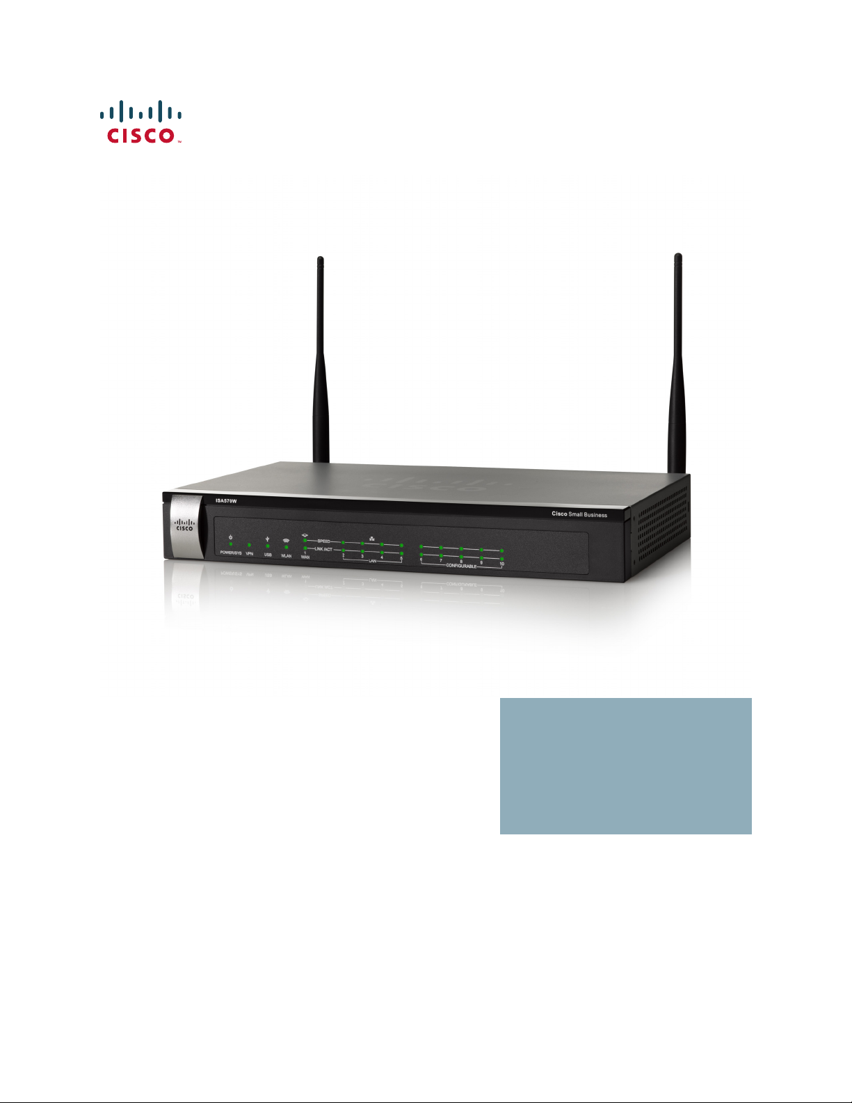
Thank you for choosing the Cisco ISA500 Series Integrated Security Appliance, a
member of the Small Business Family. The ISA500 Series is a set of Unified Threat
Management (UTM) security appliances that provide business-class security
gateway solutions with dual WAN, DMZ, zone-based firewall, site-to-site and
remote access VPN (including IPsec Remote Access, Teleworker VPN Client, and
SSL VPN) support, and Internet threat protection, such as Intrusion Prevention
(IPS), Anti-Virus, Application Control, Web URL Filtering, Web Reputation Filtering,
Spam Filter, and Network Reputation. The ISA550W and ISA570W include
802.11b/g/n access point capabilities.
The following table lists the available model numbers.
Model Description Configuration
ISA550 Cisco ISA550 Integrated
Security Appliance
ISA550W Cisco ISA550 Integrated
Security Appliance with
Wi-Fi
ISA570 Cisco ISA570 Integrated
Security Appliance
ISA570W Cisco ISA570 Integrated
Security Appliance with
Wi-Fi
NOTE Any configurable port can be configured to be a WAN, DMZ, or LAN port. Only one
configurable port can be configured as a WAN port at a time. Up to 4 configurable
ports can be configured as DMZ ports.
1 WAN port, 2 LAN ports,
4 configurable ports, and 1 USB 2.0
port
1 WAN port, 2 LAN ports,
4 configurable ports, 1 USB 2.0 port,
and 802.11b/g/n
1 WAN port, 4 LAN ports,
5 configurable ports, and 1 USB 2.0
port
1 WAN port, 4 LAN ports,
5 configurable ports, 1 USB 2.0 port,
and 802.11b/g/n
Cisco ISA500 Series Integrated Security Appliances Administration Guide 20
Page 21
Getting Started
282351
Small Business
1
VPN
USB
WAN LAN
CONFIGURABLEPOWER/SYS
SPEED
LINK /ACT
234
56
7
ISA550
Cisco
281983
Small Business
1
VPN
USB
WAN LAN
CONFIGURABLEPOWER/SYS
SPEED
LINK /ACT
234
56
7
WLAN
ISA550W
Cisco
Small Business
1
VPN
USB
WAN LAN
CONFIGURABLEPOWER/SYS
SPEED
LINK /ACT
910
234
56
7
8
WLAN
281980
ISA570W
Cisco
Product Overview
Product Overview
Before you use the security appliance, become familiar with the lights on the front
panel and the ports on the rear panel.
• Front Panel, page 21
• Back Panel, page 23
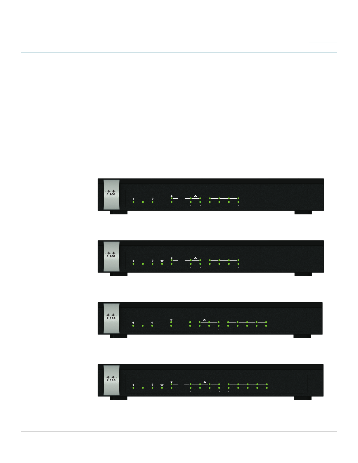
Front Panel
ISA550 Front Panel
1
ISA550W Front Panel
ISA570 Front Panel
ISA570
USB
VPN
ISA570W Front Panel
SPEED
LINK /ACT
1
WAN LAN
234
56
Small Business
Cisco
8
7
910
CONFIGURABLEPOWER/SYS
282350
Cisco ISA500 Series Integrated Security Appliances Administration Guide 21
Page 22

Getting Started
Product Overview
1
Front Panel Lights
The following table describes the lights on the front panel of the security
appliance. These lights are used for monitoring system activity.
Light Description
POWER/SYS Indicates the power and system status.
• Solid green when the system is powered on and is
operating normally.
• Flashes green when the system is booting.
• Solid amber when the system has a booting problem,
a device error occurs, or the system has a problem.
VPN Indicates the site-to-site VPN connection status.
• Solid green when there are active site-to-site VPN
connections.
• Flashes green when attempting to establish a
site-to-site VPN tunnel.
• Flashes amber when the system is experiencing
problems setting up a site-to-site VPN connection
and there is no VPN connection.
USB Indicates the USB device status.
• Solid green when a USB device is detected and is
operating normally.
• Flashes green when the USB device is transmitting
and receiving data.
WLAN
(ISA550W and
ISA570W only)
Indicates the WLAN status.
• Solid green when the WLAN is up.
• Flashes green when the WLAN is transmitting and
receiving data.
Cisco ISA500 Series Integrated Security Appliances Administration Guide 22
Page 23
Getting Started
281984
ANT02ANT01
RESET
I
/
O
POWER
12VDC
4
5
6
7
CONFIGURABLE
2
3
LAN
1
WAN
ANT01 ANT02
Reset
Button
Power
Switch
Power
Connector
WAN
Por t
USB
Por t
Configurable
Por ts
LAN
Por ts
Product Overview
1
Light Description
SPEED Indicates the traffic rate of the associated port.
• Off when the traffic rate is 10 or 100 Mbps.
• Solid green when the traffic rate is 1000 Mbps.
LINK/ACT Indicates that a connection is being made through the port.
• Solid green when the link is up.
• Flashes green when the port is transmitting and
receiving data.
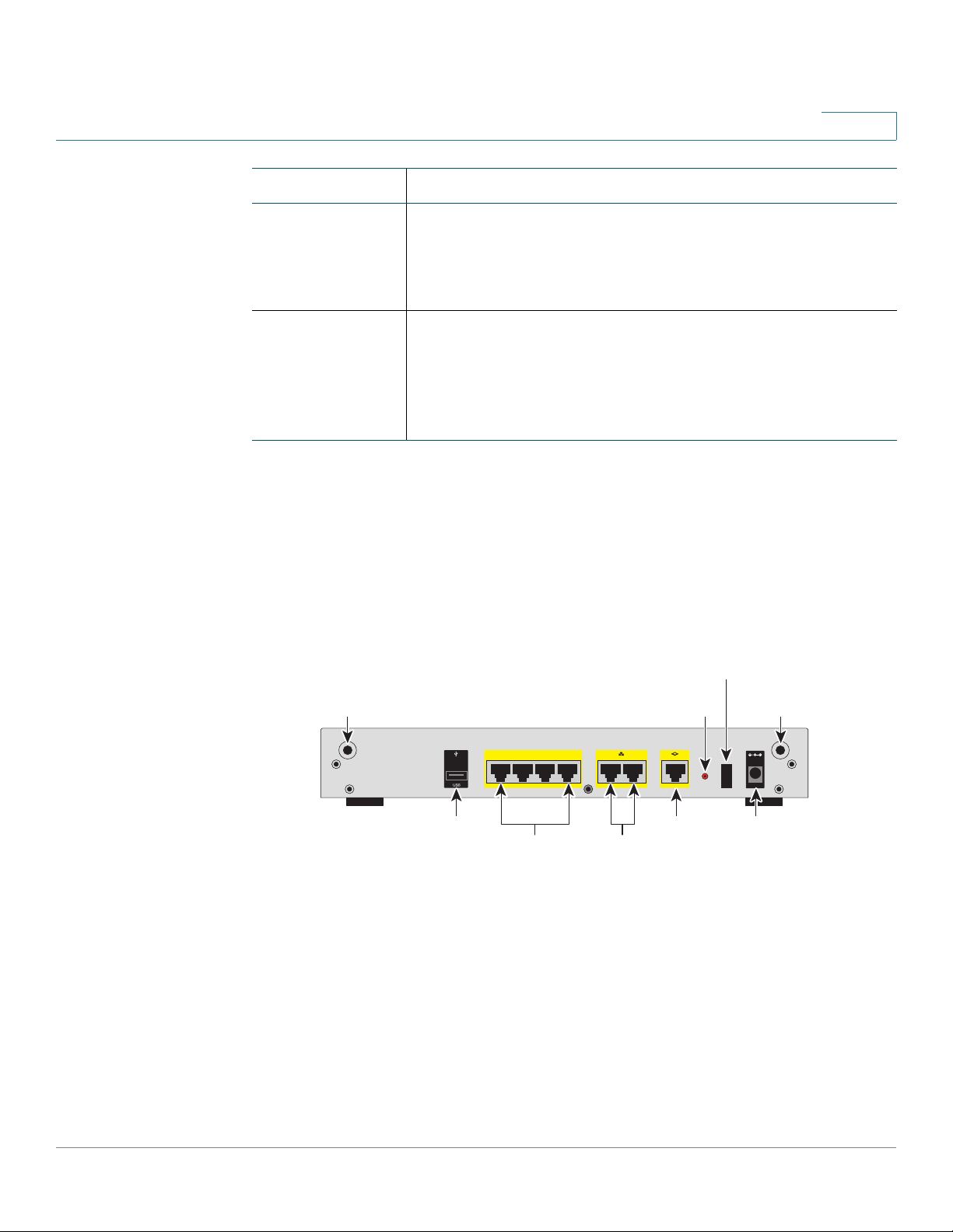
Back Panel
The back panel is where you connect the network devices. The ports on the panel
vary depending on the model.
ISA550 and ISA550W Back Panel
Cisco ISA500 Series Integrated Security Appliances Administration Guide 23
Page 24
Getting Started
281981
I
/
O
RESET
ANT02ANT01
1
6
7
8910
WAN
CONFIGURABLE
POWER
12VDC
2
3
4
5
LAN
ANT01 ANT02
Reset
Button
Power
Switch
Power
Connector
WAN
Por t
USB
Por t
Configurable
Por ts
LAN
Por ts
Product Overview
1
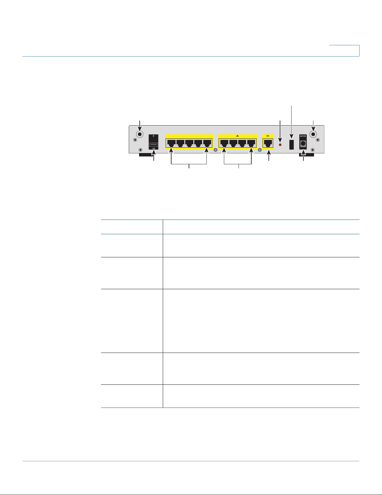
ISA570 and ISA570W Back Panel
Back Panel Descriptions
Feature Description
ANT01/ANT02 Threaded connectors for the antennas (for ISA550W and
ISA570W only).
USB Port Connects the unit to a USB device. You can use a USB
device to save and restore system configuration, or to
upgrade the firmware.
Configurable
Ports
Can be set to operate as WAN, LAN, or DMZ ports. ISA550
and ISA550W have 4 configurable ports. ISA570 and
ISA570W have 5 configurable ports.
NOTE: Only one configurable port can be configured as a
WAN port at a time. Up to 4 configurable ports can be
configured as DMZ ports.
LAN Ports Connects PCs and other network appliances to the unit.
ISA550 and ISA550W have 2 dedicated LAN ports. ISA570
and ISA570W have 4 dedicated LAN ports.
WAN Port Connects the unit to a DSL or a cable modem, or other WAN
connectivity device.
Cisco ISA500 Series Integrated Security Appliances Administration Guide 24
Page 25

Getting Started
Getting Started with the Configuration Utility
Feature Description
RESET Button To reboot the unit, push and release the RESET button for
Power Switch Powers the unit on or off.
1
less than 3 seconds.
To restore the unit to its factory default settings, push and
hold the RESET button for more than 3 seconds while the
unit is powered on and the POWER/SYS light is solid green.
The POWER/SYS light will flash green when the system is
rebooting.
Power
Connector
Connects the unit to power using the supplied power cord
and adapter.
Getting Started with the Configuration Utility
The ISA500 Series Configuration Utility is a web-based device manager that is
used to provision the security appliance. To use this utility, you must be able to
connect to the security appliance from a PC or laptop. You can access the
Configuration Utility by using the following web browsers:
• Microsoft Internet Explorer 8 and 9
• Mozilla Firefox 3.6.x, 5, and 6
NOTE The minimum recommended display resolution for the PC running the Web
browser used to access the Configuration Utility is 1024 x 768.
This section includes the following topics:
• Logging in to the Configuration Utility, page 26
• Navigating Through the Configuration Utility, page 27
• Using the Help System, page 28
• Configuration Utility Icons, page 28
Cisco ISA500 Series Integrated Security Appliances Administration Guide 25
Page 26

Getting Started
Getting Started with the Configuration Utility
Logging in to the Configuration Utility
STEP 1 Connect your computer to an available LAN port on the back panel.
Your PC will become a DHCP client of the security appliance and will receive an IP
address in the 192.168.75.x range.
STEP 2 Start a web browser. In the address bar, enter the default IP address of the
security appliance: 192.168.75.1.
NOTE: The above address is the factory default LAN address. If you change this
setting, enter the new IP address to connect to the Configuration Utility.
STEP 3 When the login page opens, enter the username and password.
The default username is cisco. The default password is cisco. Usernames and
passwords are case sensitive.
1
STEP 4 Click Login.
STEP 5 For security purposes, you must change the default password of the default
administrator account. Set a new administrator password and click OK.
STEP 6 If you can access the Internet and a newer firmware is detected, the Firmware
Upgrade window opens. Follow the on-screen prompts to download and install
the firmware. See Upgrading your Firmware After your First Login, page 33.
STEP 7 If you cannot access the Internet or you are using the latest firmware, the Setup
Wizard will now launch. Follow the on-screen prompts to complete the initial
configuration. See Using the Setup Wizard for the Initial Configuration, page 36.
Cisco ISA500 Series Integrated Security Appliances Administration Guide 26
Page 27
Getting Started
1
2
Getting Started with the Configuration Utility
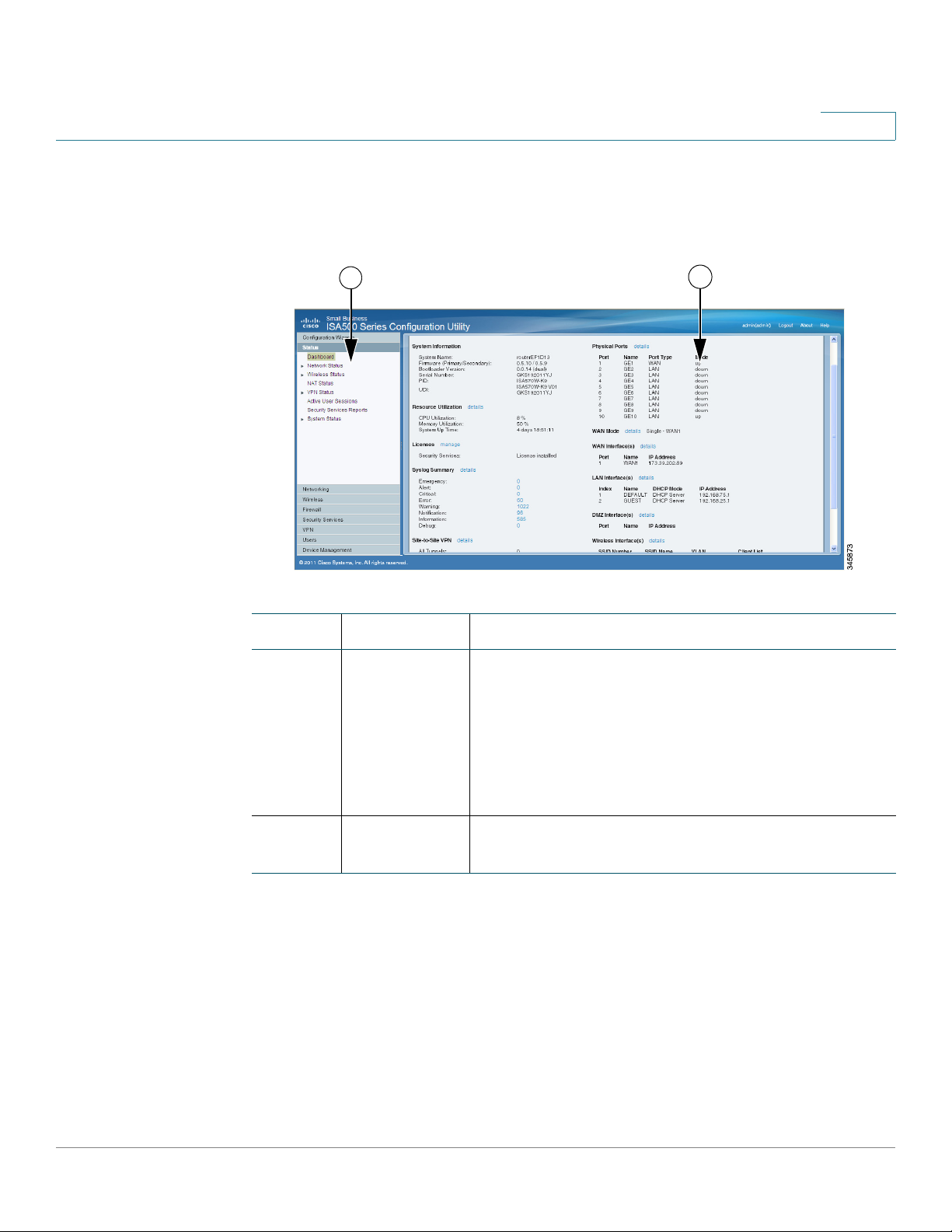
Navigating Through the Configuration Utility
Use the left hand navigation pane to perform the tasks in the Configuration Utility.
1
Number Component Description
1Left Hand
Navigation
Pane
2 Main Content The main content of the feature or sub-feature
The left hand navigation pane provides easy
navigation through the configurable features. The
main branches expand to provide the features. Click
the main branch title to expand its contents. Click
the triangle next to a feature to expand or contract
its sub-features. Click the title of a feature or
sub-feature to open it.
appears in this area.
Cisco ISA500 Series Integrated Security Appliances Administration Guide 27
Page 28
Getting Started
Getting Started with the Configuration Utility
Using the Help System
The Configuration Utility provides a context-sensitive help file for all configuration
tasks. To view the Help page, click the Help link in the top right corner of the
screen. A new window opens with information about the page that you are
currently viewing.
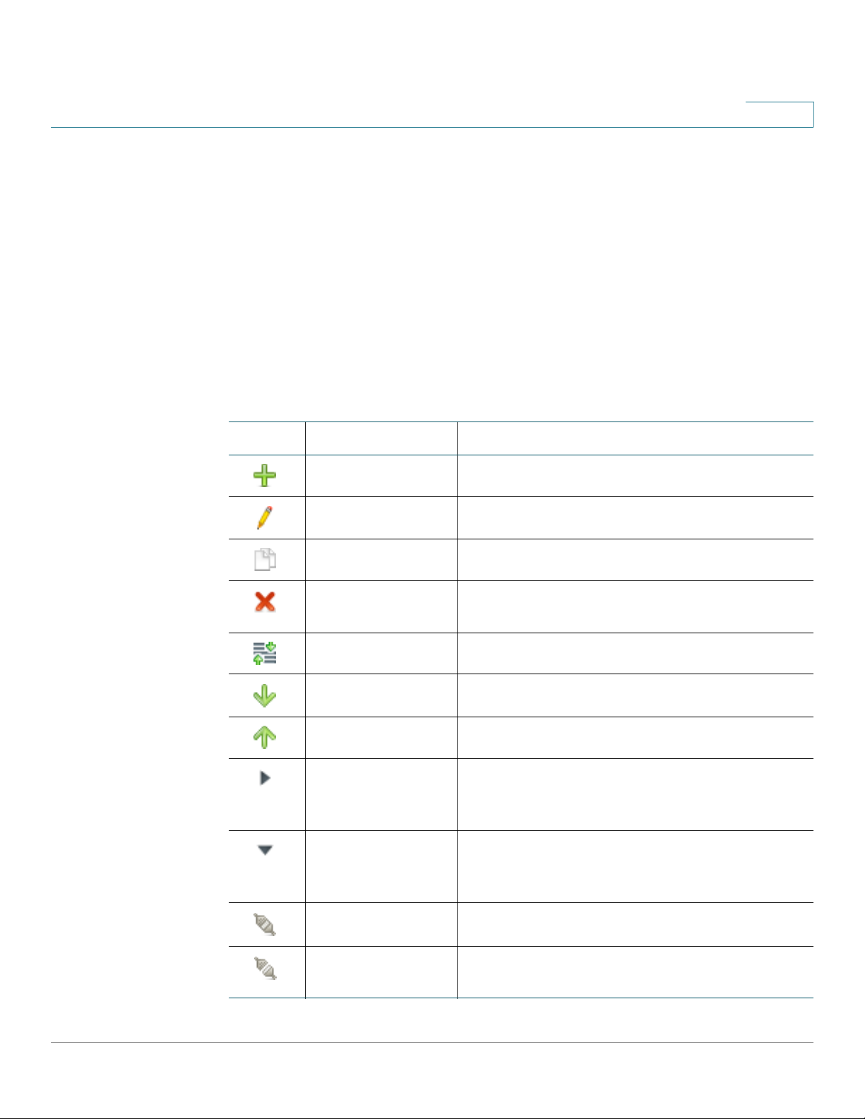
Configuration Utility Icons
The Configuration Utility has icons for commonly used configuration options. The
following table describes these icons:
Icon Description Action
1
Add icon Add an entry.
Edit icon Edit an entry.
Duplicate icon
Delete icon Delete an entry or delete multiple selected
Move icon Move an item to a specific location.
Move down icon Move an item down one position.
Move up icon Move an item up one position.
Expand triangle
icon
Contract triangle
icon
Create a copy of an existing entry.
entries.
Expand the sub-features of a feature in the left
navigation pane or expand the items under a
category.
Contract the sub-features of a feature in the left
navigation pane or contract the items under a
category.
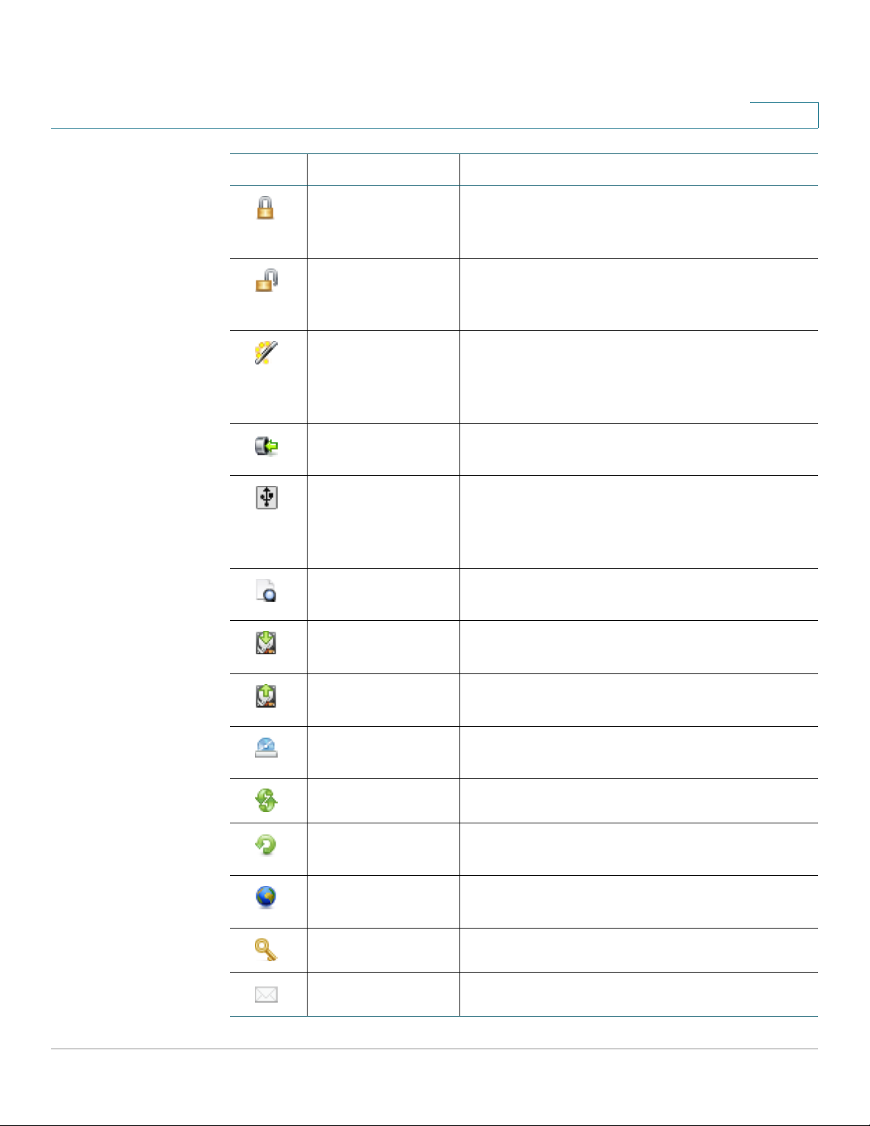
Connect icon Establish a VPN connection.
Disconnect or
Logout icon
Cisco ISA500 Series Integrated Security Appliances Administration Guide 28
Terminate a VPN connection or an active user
session.
Page 29
Getting Started
Getting Started with the Configuration Utility
Icon Description Action
1
Forced Authorized
icon
Forced
Unauthorized icon
Auto icon Enable 802.1x access control and cause the
Import PC icon Import a local certificate or a CA certificate
Export to USB or
Import from USB
icon
Details icon View the details of a certificate or a Certificate
Disable 802.1x access control and cause the
port to transition to the authorized state without
any authentication exchange required.
Cause the port to remain in the unauthorized
state, ignoring all attempts by the client to
authenticate.
port to begin in the unauthorized state, allowing
only EAPOL frames to be sent and received
through the port.
from PC.
Export a local certificate, a CA certificate, or a
Certificate Signing Request to a USB key, or
import a local certificate or a CA certificate
from a USB key.
Signing Request.
Download icon Download a local certificate, a CA certificate, or
a Certificate Signing Request to PC.
Upload icon Upload a signed certificate for the Certificate
Signing Request from PC.
Install or Renew
icon
Refresh icon Refresh the data.
Reset icon Reset the device to the factory defaults, or
Check for Updates
Now icon
Credentials icon View the device credentials.
Email Alerts icon View or configure the email alert settings.
Install the security license.
renew the security license.
Check for new signature updates from Cisco’s
signature server immediately.
Cisco ISA500 Series Integrated Security Appliances Administration Guide 29
Page 30

Getting Started
Factory Default Settings
Factory Default Settings
The security appliance is preconfigured with settings to allow you to start using
the device with minimal changes. Depending on the requirements of your Internet
Service Provider (ISP) and the needs of your business, you may need to modify
some of these settings. You can use the Configuration Utility to customize all
settings, as needed.
This section includes the following topics:
• Default Settings of Key Features, page 30
• Restoring the Factory Default Settings, page 31
Default Settings of Key Features
1
The default settings of key features are described below. For a full list of all factory
default settings, see Factory Default Settings, page 461.
• IP Routing Mode: By default, only the IPv4 mode is enabled. To support
IPv4 and IPv6 addressing, enable the IPv4/IPv6 mode. See Configuring IPv4
or IPv6 Routing, page116.
• WAN Configuration: By default, the security appliance is configured to
obtain an IP address from your ISP using Dynamic Host Configuration
Protocol (DHCP). Depending on the requirement of your ISP, configure the
network addressing mode for the primary WAN. You can change other WAN
settings as well. See Configuring WAN Settings for Your Internet
Connection, page122.
• LAN Configuration: By default, the LAN of the security appliance is
configured in the 192.168.75.0 subnet and the LAN IP address is
192.168.75.1. The security appliance acts as a DHCP server to the hosts on
the LAN network. It can automatically assign IP addresses and DNS server
addresses to the PCs and other devices on the LAN. For most deployment
scenarios, the default DHCP and TCP/IP settings should be satisfactory.
However, you can change the subnet address or the default IP address. See
Configuring a VLAN, page 137.
• VLAN Configuration: The security appliance predefines a native VLAN
(DEFAULT) and a guest VLAN (GUEST). You can customize the predefined
VLANs or create new VLANs for your specific business needs. See
Configuring a VLAN, page 137.
Cisco ISA500 Series Integrated Security Appliances Administration Guide 30
Page 31

Getting Started
Factory Default Settings
1
• Configurable Ports: Any configurable port can be configured to be a WAN,
DMZ, or LAN port. By default, all configurable ports are set to be LAN ports.
Only one configurable port can be configured as a WAN port at a time (See
Configuring the WAN, page 122). Up to four configurable ports can be
configured as DMZ ports (see Configuring DMZ, page 141).
• Wireless Network (for ISA550W and ISA570W only): ISA550W and
ISA570W are configured with four SSIDs. All SSIDs are disabled by default.
For security purposes, we strongly recommend that you configure the
SSIDs with the appropriate security settings. See Wireless (for ISA550W
and ISA570W only), page 206.
• Administrative Access: You can access the Configuration Utility by using a
web browser from the LAN side and entering the default LAN IP address of
192.168.75.1. You can log on by entering the username (cisco) and
password (cisco) of the default administrator account. To prevent
unauthorized access, you must immediately change the administrator
password at the first login and are encouraged to change the username for
the default administrator account. See Changing the Default Administrator
Password, page 32.
• Security Services: By default, the security services such as Intrusion
Prevention (IPS), Anti-Virus, Application Control, Web URL Filtering, Web
Reputation Filtering, and Spam Filter are disabled. See Chapter 7,
"Security Services."
• Firewall: By default, the firewall prevents inbound traffic and allows all
outbound traffic. If you want to allow some inbound traffic or prevent some
outbound traffic, you must customize firewall rules. Up to 100 custom
firewall rules can be configured on the security appliance. See Configuring
Firewall Rules to Control Inbound and Outbound Traffic, page 252.
• VPN: By default, the VPN feature is disabled. The security appliance can
function as an IPsec VPN server, a Teleworker VPN client, or as a SSL VPN
gateway so that remote users can securely access the corporate network
resources over the VPN tunnels. You can also establish a secure IPsec VPN
tunnel between two sites that are physically separated by using the
Site-to-Site VPN feature. See VPN, page 333.
Restoring the Factory Default Settings
To restore the factory defaults, choose one of the following actions:
• Press and hold the RESET button on the back panel of the unit for more than
3 seconds while the unit is powered on and the POWER/SYS light is solid
Cisco ISA500 Series Integrated Security Appliances Administration Guide 31
Page 32

Getting Started
Performing Basic Configuration Tasks
• Or launch the Configuration Utility and login. Click Device Management >
After a restore to factory defaults, the following settings apply:
Parameter Default Value
Username cisco
Password cisco
LAN IP 192.168.75.1
1
green. Release the button and wait for the unit to reboot. The POWER/SYS
light will flash green when the system is rebooting.
Reboot/Reset in the left hand navigation pane. In the Reset Device area,
click Reset to Factory Defaults.
DHCP Range 192.168.75.100 to 200
Performing Basic Configuration Tasks
We recommend that you complete the following tasks before you configure the
security appliance:
• Changing the Default Administrator Password, page 32
• Upgrading your Firmware After your First Login, page 33
• Backing Up Your Configuration, page 34
Changing the Default Administrator Password
The default administrator account (“cisco”) has full privilege to set the
configuration and read the system status. For security purposes, you must change
the default administrator password at the first login.
STEP 1 Enter the following information:
• User name: Enter the current username or enter a new username if you want
to change the default username.
Cisco ISA500 Series Integrated Security Appliances Administration Guide 32
Page 33

Getting Started
Performing Basic Configuration Tasks
• New password: Enter a new administrator password. Passwords are case
• Confirm password: Enter the new administrator password again for
STEP 2 Click OK to save your settings.
Upgrading your Firmware After your First Login
1
sensitive.
NOTE: A password requires a minimum of 8 characters, including at least
three of these character classes: uppercase letters, lowercase letters, digits,
and special characters. Do not repeat any password more than three times
in a row. Do not set the password as the username or “cisco.” Do not
capitalize or spell these words backwards.
confirmation.
The security appliance uses a built-in IDA client to query the firmware from Cisco’s
IDA server. If a newer firmware is detected after you log in to the Configuration
Utility for the first time, we recommend that you upgrade your firmware to the
latest version before you do any other tasks. This feature requires that you have an
active WAN connection to access the Internet.
STEP 1 Log in to the Configuration Utility for the first time and change the default
administrator password. See Logging in to the Configuration Utility, page 26.
If newer firmware is detected, the Firmware Upgrade window opens. The version
number for the firmware that you are currently using and the version number for
the latest firmware that is detected are displayed.
STEP 2 Enter your Cisco.com account credentials in the Username and Password fields.
A valid Cisco.com account is required to download and install the firmware from
Cisco.com. If you do not have one, go to this page:
https:// tools.cisco.com/RPF/register/register.do
Then click the Create a Cisco.com Account link to register a Cisco.com account.
NOTE: Skip this step if your Cisco.com account credentials are already configured
on the security appliance.
STEP 3 Click Continue.
Cisco ISA500 Series Integrated Security Appliances Administration Guide 33
Page 34

Getting Started
Performing Basic Configuration Tasks
NOTE: You can click Install Later to upgrade the firmware later. An Upgrade
Available link will be displayed at the top right corner of the screen and the Setup
Wizard will now launch. We strongly recommend that you upgrade the firmware
immediately.
STEP 4 Validate your Cisco.com account credentials through the Internet. If your
Cisco.com account credentials are valid, the security appliance starts
downloading and installing the firmware. This process will take several minutes.
STEP 5 The security appliance reboots after the firmware is upgraded. You will be
redirected to the login screen when the security appliance boots up.
STEP 6 Log in to the Configuration Utility again. The Setup Wizard will launch. Follow the
on-screen prompts to complete the initial configuration. See Using the Setup
Wizard for the Initial Configuration, page 36.
1
NOTE Other options to upgrade the firmware:
• If you cannot access the Internet after you log in to the Configuration Utility
for the first time, you can use the Setup Wizard to configure your Internet
connection and then automatically check for firmware updates after the
Setup Wizard is complete. The Setup Wizard also allows you to manually
upgrade the firmware from a firmware image stored on your local PC. See
Using the Setup Wizard for the Initial Configuration, page 36.
• You can manually upgrade the firmware from a firmware image stored on
your PC or on a USB device. You must first download the latest firmware
image from Cisco.com and save it to your local PC or to a USB device. See
Upgrading Firmware from a PC or a USB Device, page 437.
• The security appliance automatically checks for firmware updates from
Cisco’s IDA server every 24 hours. You can upgrade your firmware to the
latest version if a newer firmware is available on Cisco.com. This feature
requires that you have an active WAN connection and a valid Cisco.com
account is configured on the security appliance in advance. See Upgrading
your Firmware from Cisco.com, page 436.
Backing Up Your Configuration
At any point during the configuration process, you can back up your configuration.
Later, if you make changes that you want to abandon, you can easily restore the
saved configuration. See Backing Up and Restoring a Configuration, page 416.
Cisco ISA500 Series Integrated Security Appliances Administration Guide 34
Page 35

Configuration Wizards
This chapter describes how to use the configuration wizards to configure the
security appliance. It includes the following sections:
• Using the Setup Wizard for the Initial Configuration, page 36
• Using the Dual WAN Wizard to Configure WAN Redundancy Settings,
page 51
• Using the Remote Access VPN Wizard, page 54
• Using the Site-to-Site VPN Wizard to Configure Site-to-Site VPN,
page 66
• Using the DMZ Wizard to Configure DMZ Settings, page 71
2
• Using the Wireless Wizard (for ISA550W and ISA570W only), page 76
To access the Configuration Wizards pages, click Configuration Wizards in the
left hand navigation pane.
Cisco ISA500 Series Integrated Security Appliances Administration Guide 35
Page 36

Configuration Wizards
Using the Setup Wizard for the Initial Configuration
Using the Setup Wizard for the Initial Configuration
Use the Setup Wizard to quickly configure the primary features of your security
appliance, such as Cisco.com account credentials, security license, remote
administration, port, WAN, LAN, DMZ, WAN redundancy, WLAN (for ISA550W and
ISA570W only), and security services. Refer to the following steps:
• Starting the Setup Wizard, page 37
• Configuring Cisco.com Account Credentials, page 37
• Enabling Firmware Upgrade, page 38
• Validating Security License, page 39
• Enabling Bonjour and CDP Discovery Protocols, page 39
2
• Configuring Remote Administration, page 40
• Configuring Physical Ports, page 41
• Configuring the Primary WAN, page 42
• Configuring the Secondary WAN, page 42
• Configuring WAN Redundancy, page 42
• Configuring Default LAN Settings, page 43
• Configuring DMZ, page 44
• Configuring DMZ Services, page 45
• Configuring Wireless Radio Settings, page 47
• Configuring Intranet WLAN Access, page 48
• Configure Security Services, page 49
• Viewing Configuration Summary, page 50
NOTE Before you use the Setup Wizard to configure your security appliance, we
recommend that you have the following requirements:
• An active WAN connection for verifying your Cisco.com account
credentials, validating the security license, and upgrading your firmware to
the latest version from Cisco.com.
Cisco ISA500 Series Integrated Security Appliances Administration Guide 36
Page 37

Configuration Wizards
Using the Setup Wizard for the Initial Configuration
• A valid Cisco.com account for validating the security license and upgrading
your firmware to the latest version from Cisco.com. To register a Cisco.com
account, go to https:// tools.cisco.com/RPF/register/register.do.
• The Product Authorization Key (PAK), or license code, for validating the
security license and activating security services. You can find the license
code from the Software License Claim Certificate that Cisco provides upon
purchase of the security appliance.
Starting the Setup Wizard
STEP 1 When you log in to the Configuration Utility for the first time, the Setup Wizard may
launch automatically. To launch the Setup Wizard at any time, click Configuration
Wizards > Setup Wizard.
2
The Getting Started page appears If you have applied a configuration, a warning
message appears saying “Continuing with the Setup Wizard will overwrite some
of your previously modified parameters.” Read the warning message carefully
before you start configuring.
STEP 2 Click Next.
Configuring Cisco.com Account Credentials
STEP 3 Use the Cisco.com Credentials page to configure your Cisco.com account
credentials.
A valid Cisco.com account is required to download the latest firmware image from
Cisco.com, validate the security license, and check for signature updates from
Cisco’s signature server for IPS, Application Control, and Anti-Virus. If you do not
already have one, go to https:// tools.cisco.com/RPF/register/register.do by
clicking the Create a Cisco.com Account link to register a Cisco.com account.
• Username: Enter the username of your Cisco.com account.
• Password: Enter the password of your Cisco.com account.
STEP 4 Click Next.
If you can access the Internet, the Setup Wizard will validate your Cisco.com
account credentials through the Internet after you click Next.
If you cannot access the Internet, the Setup Wizard will assume that your
Cisco.com account credentials are valid and proceed to next step.
Cisco ISA500 Series Integrated Security Appliances Administration Guide 37
Page 38

Configuration Wizards
Using the Setup Wizard for the Initial Configuration
NOTE: You can configure your Cisco.com account credentials on the Device
Management > Cisco Services & Support > Cisco.com Account page after the
Setup Wizard is complete. See Configuring Cisco.com Account, page 424.
STEP 5 If your Cisco.com account credentials are invalid, click OK to return to the
Cisco.com Credentials page. Correct your Cisco.com account credentials and
then click Next to verify them again.
STEP 6 If your Cisco.com account credentials are valid, proceed to the Upgrade Firmware
page.
Enabling Firmware Upgrade
STEP 7 Use the Upgrade Firmware page to enable the device to check for firmware
updates or to manually upgrade the firmware.
2
• To automatically check for firmware updates, check the box next to Check
for firmware update when Setup Wizard completes. The security
appliance will immediately check for firmware updates after the Setup
Wizard is complete. This feature requires that you have an active WAN
connection.
• To manually upgrade the firmware from a firmware image stored on your PC,
uncheck the box next to Check for firmware update when Setup Wizard
completes. Uncheck this box when you do not have an active WAN
connection and you have already downloaded the latest firmware image
from Cisco.com to your local PC.
STEP 8 If you uncheck the box, click Browse to locate and select the firmware image from
your PC, and then click Upgrade.
After you click Upgrade, the security appliance starts installing the firmware. This
process will take several minutes. Do not disconnect the power or reset the
device. Doing so will cancel the firmware upgrade process and could possibly
corrupt. The security appliance reboots after the firmware is upgraded. You will
be redirected to the login screen when the security appliance boots up.
STEP 9 If you choose to automatically check for firmware updates, click Next.
Cisco ISA500 Series Integrated Security Appliances Administration Guide 38
Page 39

Configuration Wizards
Using the Setup Wizard for the Initial Configuration
Validating Security License
STEP 10 Use the License Installation page to validate the security license, which is used to
activate security services on the device.
STEP 11 If the security license is already installed on the security appliance, click Next to
proceed next step.
STEP 12 If the security license is not installed on the security appliance, enter the following
information to validate the security license:
• Email Address: Enter the registered email address to receive the PAK ID.
• PAK I D: Enter your Product Authorization Key in this field. You can find the
license code from the Software License Claim Certificate that Cisco
provides upon purchase of the security appliance.
NOTE: A valid Cisco.com account is required to validate the security license.
If your Cisco.com account credentials are not configured, go back to the
Cisco.com Credentials page to configure them.
2
NOTE: If you want to continue the Setup Wizard configuration without installing the
security license, check the box next to Continue without installing license (not
recommended). The security services cannot be activated without installing the
security license.
STEP 13 After you are finished, click Next.
Enabling Bonjour and CDP Discovery Protocols
STEP 14 Use the Discovery page to enable Bonjour and/or CDP discovery protocols on the
security appliance. For optimal device discovery and topology support via the
OnPlus portal, enable both discovery protocols.
• Enable Bonjour Discovery Protocol: Check this box to enable Bonjour
discovery protocol, or uncheck this box to disable it.
• Enable Cisco Discovery Protocol (CDP): Check this box to enable Cisco
Discovery Protocol (CDP), or uncheck this box to disable it.
NOTE: Discovery protocols are only operational on the LAN ports of the
security appliance.
STEP 15 After you are finished, click Next.
Cisco ISA500 Series Integrated Security Appliances Administration Guide 39
Page 40

Configuration Wizards
Using the Setup Wizard for the Initial Configuration
Configuring Remote Administration
STEP 16 Use the Remote Administration page to configure the remote management
settings. The security appliance allows remote management securely by using
HTTPS and HTTP, for example https://xxx.xxx.xxx.xxx:8080.
• Remote Administration: Click On to enable remote management by using
HTTPS, or click Off to disable it. We recommend that you use HTTPS for
secure remote management.
• HTTPS Listen Port Number: If you enable remote management by using
HTTPS, enter the port number. By default, the listen port number for HTTPS
is 8080.
• HTTP Enable: Click On to enable remote management by using HTTP, or
click Off to disable it.
2
• HTTP Listen Port Number: If you enable remote management by using
HTTP, enter the port number. By default, the listen port number for HTTP is
80.
• Allow Address: To specify the devices that can access the configuration
utility through the WAN interface, choose an Address Object or enter an
address.
- Address Objects: These objects represent known IP addresses and
address ranges, such as the GUEST VLAN and the DHCP pool. After
completing the wizard, you can view information about Address Objects
on the Networking > Address Management page.
- Create new address: Choose this option to enter an IP address or
address range. In the pop-up window, enter a Name and specify the
Type (Host or Range). For a single host, enter the IP address. For a range,
enter the Starting IP Address and the Ending IP Address.
• Remote SNMP: Click On to enable SNMP for remote connection, or click Off
to disable SNMP. Enabling SNMP allows remote users to use the SNMP
protocol to access the Configuration Utility.
STEP 17 After you are finished, click Next.
Cisco ISA500 Series Integrated Security Appliances Administration Guide 40
Page 41

Configuration Wizards
Using the Setup Wizard for the Initial Configuration
Configuring Physical Ports
STEP 18 Use the Port Configuration page to specify the port configuration.
If you are using the ISA570 or ISA570W, choose one of the following options:
• 1 WAN, 9 LAN switch: One WAN port (WAN1) and nine LAN ports are
configured.
• 1 WAN, 1 DMZ, 8 LAN switch: One WAN port (WAN1), one DMZ port, and
eight LAN ports are configured. The configurable port GE10 is set as a DMZ
port.
• 1 WAN, 1 WAN backup, 8 LAN switch: Tw o WA N po r ts ( WA N1 i s t h e
primary WAN and WAN2 is the secondary WAN) and eight LAN ports are
configured. The configurable port GE10 is set as the secondary WAN port.
• 1 WAN, 1 WAN backup, 1 DMZ, 7 LAN switch: Tw o WA N po r ts ( WA N1 i s
the primary WAN and WAN2 is the secondary WAN), one DMZ port, and
seven LAN ports are configured. The configurable port GE10 is set as the
secondary WAN port and the configurable port GE9 is set as a DMZ port.
2
If you are using the ISA550 or ISA550W, choose one of the following options:
• 1 WAN, 6 LAN switch: One WAN port (WAN1) and six LAN ports are
configured.
• 1 WAN, 1 DMZ, 5 LAN switch: One WAN port (WAN1), one DMZ port, and
five LAN ports are configured. The configurable port GE7 is set as a DMZ
port.
• 1 WAN, 1 WAN backup, 5 LAN switch: Tw o WA N po r ts ( WA N1 i s t h e
primary WAN and WAN2 is the secondary WAN) and five LAN ports are
configured. The configurable port GE7 is set as the secondary WAN port.
• 1 WAN, 1 WAN backup, 1 DMZ, 4 LAN switch: Tw o WA N po r ts ( WA N1 i s
the primary WAN and WAN2 is the secondary WAN), one DMZ port, and four
LAN ports are configured. The configurable port GE7 is set as the secondary
WAN port and the configurable port GE6 is set as a DMZ port.
NOTE: If you have two ISP links, we recommend that you set
that you can provide backup connectivity or load balancing. If you need to host
public services, we recommend that you set a DMZ port.
STEP 19 After you are finished, click Next.
a backup WAN so
Cisco ISA500 Series Integrated Security Appliances Administration Guide 41
Page 42

Configuration Wizards
Using the Setup Wizard for the Initial Configuration
Configuring the Primary WAN
STEP 20 Use the Primary WAN Connection page to configure the primary WAN connection
by using the account information provided by your ISP.
• WAN Name: The name of the primary WAN port.
• IP Address Assignment: Depending on the requirements of your ISP,
choose the network addressing mode and configure the corresponding
fields for the primary WAN port. The security appliance supports DHCP
Client, Static IP, PPPoE, PPTP, and L2TP. For complete details, see Network
Addressing Mode, page125.
STEP 21 After you are finished, click Next.
Configuring the Secondary WAN
2
STEP 22 If only one WAN port is configured, proceed to Configuring Default LAN
Settings, page 43. If two WAN ports are configured, use the Secondary WAN
Connection page to configure the secondary WAN connection by using the
account information provided by your ISP.
• WAN Name: The name of the secondary WAN port.
• IP Address Assignment: Depending on the requirements of your ISP,
choose the network addressing mode and configure the corresponding
fields for the secondary WAN port. For complete details, see Network
Addressing Mode, page125.
STEP 23 After you are finished, click Next.
Configuring WAN Redundancy
STEP 24 If you have two WAN links, use the WAN Redundancy page to determine how the
two ISP links are used.
• Equal Load Balancing (Round Robin): Choose this option if you want to
re-order the WAN ports for Round Robin selection. The order is as follows:
WAN1 and WAN2. The Round Robin will then be back to WAN1 and continue
the order.
• Weighted Load Balancing: Choose this option if you want to distribute the
bandwidth to two WAN ports by the weighted percentage or by the
weighted link bandwidth. The two links will carry data for the protocols that
are bound to them.
Cisco ISA500 Series Integrated Security Appliances Administration Guide 42
Page 43

Configuration Wizards
Using the Setup Wizard for the Initial Configuration
- Weighted By Percentage: If you choose this option, specify the
percentage of bandwidth for each WAN, such as 80% for WAN1 and 20%
for WAN2.
- Weighted by Link Bandwidth: If you choose this option, specify the
amount of bandwidth for each WAN, such as 80 Mbps for WAN1 and 20
Mbps for WAN2.
NOTE: The Weighted by Link Bandwidth option has the same effect as the
Weighted by Percentage option. However, it provides more percentage
options than in the Weighted by Percentage field.
• Failover: Choose this option if you want to use one ISP link as a backup. If a
failure is detected on the primary link, then the security appliance directs all
Internet traffic to the backup link. When the primary link regains connectivity,
all Internet traffic is directed to the primary link and the backup link becomes
idle.
2
- Select WAN Precedence: Choose one of the following options:
Primary: WAN1; Secondary: WAN2: If you choose this option, WAN1 is
set as the primary link and WAN2 is set as the backup link.
Primary: WAN2; Secondary: WAN1: If you choose this option, WAN2 is
set as the primary link and WAN1 is set as the backup link.
- Preempt Delay Timer: Enter the time in seconds that the security
appliance will preempt the primary link from the backup link after the
primary link is up again. The default is 5 seconds.
STEP 25 After you are finished, click Next.
Configuring Default LAN Settings
STEP 26 Use the LAN Configuration page to configure the default LAN settings.
• IP Address: Enter the subnet IP address for the default LAN.
• Netmask: Enter the subnet mask for the default LAN.
• DHCP Mode: Choose one of the following DHCP modes:
- Disable: Choose this option if the computers on the LAN are configured
with static IP addresses or are configured to use another DHCP server.
Cisco ISA500 Series Integrated Security Appliances Administration Guide 43
Page 44

Configuration Wizards
Using the Setup Wizard for the Initial Configuration
- DHCP Server: Allows the security appliance to act as a DHCP server and
assigns IP addresses to all devices that are connected to the LAN. Any
new DHCP client joining the LAN is assigned an IP address of the DHCP
pool.
- DHCP Relay: Allows the security appliance to use a DHCP Relay. If you
choose DHCP Relay, enter the IP address of the remote DHCP server in
the Relay IP field.
STEP 27 If you choose DHCP Server as the DHCP mode, enter the following information:
• Start IP: Enter the starting IP address of the DHCP pool.
• End IP: Enter the ending IP address of the DHCP pool.
NOTE: The Start IP address and End IP address should be in the same
subnet as the LAN IP address.
2
• Lease Time: Enter the maximum connection time that a dynamic IP address
is “leased” to a network user. When the time elapses, the user is
automatically renewed the dynamic IP address.
• DNS1: Enter the IP address of the primary DNS server.
• DNS2: Optionally, enter the IP address of the secondary DNS server.
• WINS1: Optionally, enter the IP address of the primary WINS server.
• WINS2: Optionally, enter the IP address of the secondary WINS server.
• Domain Name: Optionally, enter the domain name for the default LAN.
• Default Gateway: Enter the IP address of default gateway.
STEP 28 After you are finished, click Next.
Configuring DMZ
STEP 29 If you have not configured a DMZ port, proceed to Configuring Wireless Radio
Settings, page 47. If you configured a DMZ port, use the DMZ Configuration page
to configure a DMZ network.
• IP Address: Enter the subnet IP address for the DMZ.
• Netmask: Enter the subnet mask for the DMZ.
Cisco ISA500 Series Integrated Security Appliances Administration Guide 44
Page 45

Configuration Wizards
Using the Setup Wizard for the Initial Configuration
• DHCP Mode: Choose one of the following DHCP modes:
- Disable: Choose this option if the computers on the DMZ are configured
with static IP addresses or are configured to use another DHCP server.
- DHCP Server: Allows the security appliance to act as a DHCP server and
assigns IP addresses to all devices that are connected to the DMZ. Any
new DHCP client joining the DMZ is assigned an IP address of the DHCP
pool.
- DHCP Relay: Allows the security appliance to use a DHCP Relay. If you
choose DHCP Relay, enter the IP address of the remote DHCP server in
the Relay IP field.
STEP 30 If you choose DHCP Server as the DHCP mode, enter the following information:
• Start IP: Enter the starting IP address of the DHCP pool.
2
• End IP: Enter the ending IP address of the DHCP pool.
NOTE: The Start IP address and End IP address should be in the same
subnet with the DMZ IP address.
• Lease Time: Enter the maximum connection time that a dynamic IP address
is “leased” to a network user. When the time elapses, the user is
automatically renewed the dynamic IP address.
• DNS1: Enter the IP address of the primary DNS server.
• DNS2: Optionally, enter the IP address of the secondary DNS server.
• WINS1: Optionally, enter the IP address of the primary WINS server.
• WINS2: Optionally, enter the IP address of the secondary WINS server.
• Domain Name: Optionally, enter the domain name for the DMZ.
• Default Gateway: Enter the IP address of default gateway.
STEP 31 After you are finished, click Next.
Configuring DMZ Services
STEP 32 Use the DMZ Service page to configure the DMZ services.
STEP 33 Click Add to create a DMZ service.
Other options: To edit an entry, click the Edit (pencil) icon. To delete an entry, click
the Delete (x) icon. To delete multiple entries, check them and click Delete.
Cisco ISA500 Series Integrated Security Appliances Administration Guide 45
Page 46

Configuration Wizards
Using the Setup Wizard for the Initial Configuration
STEP 34 In the DMZ Service - Add/Edit window, enter the following information:
• Original Service: Choose a service as the incoming service.
• Translated Service: Choose a service as the translated service or choose
Original if the translated service is same as the incoming service. If the
service that you want is not in the list, choose Create a new service to
create a new service object. To maintain the service objects, go to the
Networking > Service Management page. See Service Management,
page177.
NOTE: One-to-one translation will be performed for port range forwarding.
For example, if you want to translate an original TCP service with the port
range of 50000 to 50002 to a TCP service with the port range of 60000 to
60002, then the port 50000 will be translated to the port 60000, the port
50001 will be translated to the port 60001, and the port 50002 will be
translated to the port 60002.
2
• Translated IP: Choose the IP address of your local server that needs to be
translated. If the IP address that you want is not in the list, choose Create a
new address to create a new IP address object. To maintain the IP address
objects, go to the Networking > Address Management page. See Address
Management, page 175.
• WAN: Choose either WAN1 or WAN2, or both as the incoming WAN port.
• WAN IP: Specify the public IP address for the server. You can use the IP
address of the selected WAN port or a public IP address that is provided by
your ISP. When you choose Both as the incoming WAN port, this option is
grayed out.
• Enable DMZ Service: Click On to enable the DMZ service, or click Off to
create only the DMZ service.
• Create Firewall Rule: Check this box to automatically create a firewall rule
to allow access for this DMZ service. You must manually create a firewall rule
if you uncheck this box.
NOTE: If you choose Both as the incoming WAN port, a firewall rule from Any
zone to Any zone will be created accordingly.
• Description: Enter the name for the DMZ service.
Cisco ISA500 Series Integrated Security Appliances Administration Guide 46
Page 47

Configuration Wizards
Using the Setup Wizard for the Initial Configuration
For example, you host an RDP server (192.168.12.101) on the DMZ. Your ISP
has provided a static IP address (172.39.202.102) that you want to expose to
the public as your RDP server address. You can create a DMZ service as
follows to allow Internet user to access the RDP server by using the
specified public IP address.
Original Service RDP
Translated Service RDP
Translated IP RDPServer
WAN WA N1
WAN IP PublicIP
2
Enable DMZ Service On
Create Firewall Rule On
NOTE: In this example, you must manually create two address objects (RDPServer
and PublicIP) and a TCP service object with the port 3389 called “RDP.”
STEP 35 Click OK to save your settings.
STEP 36 After you are finished, click Next.
Configuring Wireless Radio Settings
STEP 37 If you are using the ISA550 or ISA570, proceed to Viewing Configuration
Summary, page 50. If you are using the ISA550W or ISA570W, use the Wireless
Radio Setting page to configure the wireless radio settings.
• Wireless Radio: Click On to turn wireless radio on and hence enable the
SSID called “cisco-data,” or click Off to turn wireless radio off.
• Wireless Network Mode: Choose the 802.11 modulation technique.
- 802.11b/g mixed: Choose this mode if some devices in the wireless
network use 802.11b and others use 802.11g. Both 802.11b and 802.11g
clients can connect to the access point.
- 802.11g/n mixed: Choose this mode if some devices in the wireless
network use 802.11g and others use 802.11n Both 802.11g and 802.11n
clients can connect to the access point.
Cisco ISA500 Series Integrated Security Appliances Administration Guide 47
Page 48

Configuration Wizards
Using the Setup Wizard for the Initial Configuration
- 802.11b/g/n mixed: Choose this mode to allow 802.11b, 802.11g, and
802.11n clients operating in the 2.4 GHz frequency to connect to the
access point.
- 802.11n only: Choose this mode if all devices in the wireless network
can support 802.11n. Only 802.11n clients operating in the 2.4 GHz
frequency can connect to the access point.
• Wireless Channel: Choose a channel from a list of channels or choose Auto
to let the system determine the optimal channel to use based on the
environmental noise levels for the available channels.
STEP 38 After you are finished, click Next.
Configuring Intranet WLAN Access
2
STEP 39 If you turned the wireless radio off, proceed to Viewing Configuration Summary,
page 50. If you turned the wireless radio on, use the Intranet WLAN Access page
to configure the wireless connectivity settings for the SSID called “cisco-data.”
• SSID Name: The name of the SSID.
• Security Mode: Choose the encryption algorithm for data encryption for this
SSID and configure the corresponding settings. For complete details, see
Configuring Wireless Security, page 211.
• VLAN Name: Choose the VLAN to which this SSID is mapped. All traffic from
the wireless clients that are connected to this SSID will be directed to the
selected VLAN. For Intranet VLAN access, you must choose a VLAN that is
mapped to a trusted zone.
NOTE: ISA550W and ISA570W support four SSIDs. To configure the
wireless connectivity settings for other SSIDs, go to the Wireless > Basic
Settings page (see Configuring SSID Profiles, page 210), or use the Wireless
Wizard (see Using the Wireless Wizard (for ISA550W and ISA570W only),
page 76).
STEP 40 After you are finished, click Next.
Cisco ISA500 Series Integrated Security Appliances Administration Guide 48
Page 49

Configuration Wizards
Using the Setup Wizard for the Initial Configuration
Configure Security Services
STEP 41 Use the Security Services page to enable security services and to specify how to
handle the affected traffic when the reputation-based security services are
unavailable.
NOTE:
• Enabling a security service will apply its default settings on the security
appliance to provide a moderate level of protection. We strongly
recommend that you customize the settings for each enabled security
service after the Setup Wizard is complete. For complete details, see
Chapter 7, "Security Services."
• Application Control and Web URL Filtering need additional configuration on
the Security Services pages.
2
• A valid security license is required to activate security services. If the
security license is not yet installed, go back the License Installation page to
enter the Product Authorization Key (PAK) and email address. After the Setup
Wizard is complete, the security appliance first validates the security license
through the Internet and then activates security services.
The following features are available:
• Anti-Virus: Anti-Virus blocks viruses and malware from entering your
network through email, web, FTP, CIFS, and NetBIOS applications. Check this
box to enable the Anti-Virus feature on the security appliance, or uncheck
this box to disable it.
• Intrusion Prevention (IPS): IPS monitors network protocols and prevents
attacks to client devices by analyzing and responding to certain types of
network traffic. Check this box to enable the IPS feature on the security
appliance, or uncheck this box to disable it.
• Network Reputation: Network Reputation blocks incoming traffic from IP
addresses that are known to initiate attacks throughout the Internet. Check
this box to enable the Network Reputation feature on the security appliance,
or uncheck this box to disable it. By default, Network Reputation is enabled.
• Spam Filter: Spam Filter detects and blocks email spam. Check this box to
enable the Spam Filter feature on the security appliance, or uncheck this box
to disable it. If you enable Spam Filter, enter the IP address or domain name
of your internal SMTP server in the Local SMTP Server IP Address field.
The SMTP server must have its Internet traffic routed through the security
Cisco ISA500 Series Integrated Security Appliances Administration Guide 49
Page 50

Configuration Wizards
Using the Setup Wizard for the Initial Configuration
appliance. The SMTP server or the clients that use this SMTP server can be
configured to respond to the spam and suspected spam tags that the
security appliance applies to the emails.
• Web Reputation Filtering: Web Reputation Filtering prevents client devices
from accessing dangerous websites containing viruses, spyware, malware,
or phishing links. Check this box to enable the Web Reputation Filtering
feature on the security appliance, uncheck this box to disable it.
NOTE: Clicking the Details link for a security service can open the help page
that provides complete details for the security service.
STEP 42 Spam Filter, Network Reputation, Web Reputation Filtering, and Web URL Filtering
are reputation-based security services. You can specify how to deal with the
affected traffic when these reputation services are unavailable. Choose one of the
following options:
2
• Prevent affected network traffic: All affected traffic is blocked until the
reputation-based security services are available.
• Allow affected network traffic: All affected traffic is allowed until the
reputation-based security services are available.
STEP 43 After you are finished, click Next.
Viewing Configuration Summary
STEP 44 Use the Summary page to view information about the configuration.
STEP 45 To modify any settings, click Back. If the configuration is correct, click Apply to
apply the settings.
After your configuration is successfully applied, the Setup Wizard immediately
checks for firmware updates.
STEP 46 If the Firmware Upgrade window appears, follow the on-screen prompts to
download and install the firmware. See Upgrading your Firmware After your First
Login, page 33. If you are using the latest firmware, click Finish.
Cisco ISA500 Series Integrated Security Appliances Administration Guide 50
Page 51

Configuration Wizards
Using the Dual WAN Wizard to Configure WAN Redundancy Settings
2
Using the Dual WAN Wizard to Configure WAN Redundancy
Settings
If you have two ISP links, a backup WAN is required so that you can provide
backup connectivity or load balancing. Use the Dual WAN Wizard to configure the
WAN redundancy settings. Refer to the following steps:
• Starting the Dual WAN Wizard, page 51
• Configuring a Configurable Port as a Secondary WAN Port, page 51
• Configuring the Primary WAN, page 52
• Configuring the Secondary WAN, page 52
• Configuring WAN Redundancy, page 52
• Configuring Network Failure Detection, page 53
• Viewing Configuration Summary, page 54
Starting the Dual WAN Wizard
STEP 1 Click Configuration Wizards > Dual WAN Wizard.
STEP 2 Click Next.
Configuring a Configurable Port as a Secondary WAN Port
STEP 3 On the Port Configuration page, specify a configurable port (from GE6 to GE10) as
the secondary WAN port. The physical port GE1 is reserved for the primary WAN
port.
STEP 4 After you are finished, click Next.
Cisco ISA500 Series Integrated Security Appliances Administration Guide 51
Page 52

Configuration Wizards
Using the Dual WAN Wizard to Configure WAN Redundancy Settings
Configuring the Primary WAN
STEP 5 Use the Primary WAN Connection page to configure the primary WAN connection
by using the account information provided by your ISP.
• WAN Name: The name of the primary WAN port.
• IP Address Assignment: Depending on the requirements of your ISP,
choose the network addressing mode and configure the corresponding
fields for the primary WAN port. The security appliance supports DHCP
Client, Static IP, PPPoE, PPTP, and L2TP. For complete details, see Network
Addressing Mode, page125.
STEP 6 After you are finished, click Next.
Configuring the Secondary WAN
2
STEP 7 Use the Secondary WAN Connection page to configure the secondary WAN
connection by using the account information provided by your ISP.
• WAN Name: The name of the secondary WAN port.
• IP Address Assignment: Depending on the requirements of your ISP,
choose the network addressing mode and configure the corresponding
fields for the secondary WAN port. For complete details, see Network
Addressing Mode, page125.
STEP 8 After you are finished, click Next.
Configuring WAN Redundancy
STEP 9 Use the WAN Redundancy page to determine how the two ISP links are used.
• Weighted Load Balancing: Choose this option if you want to use both ISP
links simultaneously. Load Balancing distributes the bandwidth to two WAN
ports by the weighted percentage or by the weighted link bandwidth. The
two links will carry data for the protocols that are bound to them.
- Weighted by percentage: If you choose this option, specify the
percentage for each WAN, such as 80% percentage bandwidth for WAN1
and least 20% percentage bandwidth for WAN2.
Cisco ISA500 Series Integrated Security Appliances Administration Guide 52
Page 53

Configuration Wizards
Using the Dual WAN Wizard to Configure WAN Redundancy Settings
- Weighted by Link Bandwidth: If you choose this option, specify the
amount of bandwidth for each WAN, such as 80 Mbps for WAN1 and 20
Mbps for WAN2, which indicates that 80% bandwidth is distributed to
WAN1 and at least 20% bandwidth is distributed to WAN2.
NOTE: The Weighted by Link Bandwidth option has the same effect with the
Weighted by Percentage option. It just provides more percentage options
than Weighted by Percentage that only provides three percentage options.
• Failover: Choose this option if you want to use one ISP link as a backup. The
Failover mode directs all Internet traffic to the secondary link if the primary
link is down. When the primary link regains connectivity, all Internet traffic is
directed to the primary link and the secondary link becomes idle.
- Select WAN Precedence: Choose one of the following options:
Primary: WAN1; Secondary: WAN2: If you choose this option, WAN1 is
set as the primary link and WAN2 is set as the backup link.
2
Primary: WAN2; Secondary: WAN1: If you choose this option, WAN2 is
set as the primary link and WAN1 is set as the backup link.
- Preempt Delay Timer: Enter the time in seconds that the security
appliance will preempt the primary link from the backup link after the
primary link is up again. The default is 5 seconds.
STEP 10 After you are finished, click Next.
Configuring Network Failure Detection
STEP 11 Use the Network Detection page to configure network failure detection.
• Retry Count: Enter the number of retries. The security appliance repeatedly
tries to connect to the ISP after the network failure is detected.
• Retry Timeout: Enter the interval value between two detection packets
(Ping or DNS detection).
• Ping Detection-Ping using WAN Default Gateway: If you choose this
option, ping the IP address of the default WAN gateway. If the default WAN
gateway can be detected, the network connection is active.
• DNS Detection-DNS lookup using WAN DNS Servers: If you choose this
option, the security appliance sends the DNS query for www.cisco.com to
the default WAN DNS server. If the DNS server can be detected, the network
connection is active.
Cisco ISA500 Series Integrated Security Appliances Administration Guide 53
Page 54

Configuration Wizards
Using the Remote Access VPN Wizard
STEP 12 After you are finished, click Next.
Viewing Configuration Summary
STEP 13 Use the Summary page to view information about the configuration.
STEP 14 To modify any settings, click Back. If the configuration is correct, click Finish to
apply your settings.
Using the Remote Access VPN Wizard
Use the Remote Access VPN Wizard to configure the security appliance as an
IPsec VPN server or as a SSL VPN gateway so that remote users can securely
access the corporate network resources over the VPN tunnels. The Remote
Access VPN Wizard supports the following VPN types:
2
• IPsec Remote Access: Enable the IPsec Remote Access feature and hence
set the security appliance as an IPsec VPN server. If you choose this option,
follow the on-screen prompts to configure an IPsec Remote Access group
policy and specify the users and user groups for IPsec remote access. For
complete details, see Using the Remote Access VPN Wizard for IPsec
Remote Access, page 54.
• SSL Remote Access: Enable the SSL Remote Access feature and hence
set the security appliance as a SSL VPN server. If you choose this option,
follow the on-screen prompts to configure the SSL VPN group policies and
specify the users and user groups for SSL remote access. For complete
details, see Using Remote Access VPN Wizard for SSL Remote Access,
page 60.
Using the Remote Access VPN Wizard for IPsec Remote Access
This section describes how to use the Remote Access VPN Wizard to configure an
IPsec Remote Access group policy and specify the users and user groups for
IPsec remote access. Refer to the following steps:
• Starting the Remote Access VPN Wizard, page 55
• Configuring IPsec Remote Access Group Policy, page 55
Cisco ISA500 Series Integrated Security Appliances Administration Guide 54
Page 55

Configuration Wizards
Using the Remote Access VPN Wizard
• Configuring WAN Settings, page 56
• Configuring Operation Mode, page 56
• Configuring Access Control Settings, page 57
• Configuring DNS and WINS Settings, page 57
• Configuring Backup Servers, page 58
• Configuring Split Tunneling, page 58
• Viewing Group Policy Summary, page 58
• Configuring IPsec Remote Access User Groups, page 59
• Viewing IPsec Remote Access Summary, page 59
Starting the Remote Access VPN Wizard
2
STEP 1 Click Configuration Wizards > Remote Access VPN Wizard.
STEP 2 On the Getting Started page, choose IPsec Remote Access from the VPN Tunnel
Type drop-down list.
STEP 3 Click Next.
Configuring IPsec Remote Access Group Policy
STEP 4 Use the IPsec Group Policy page to configure the following parameters of the
IPsec Remote Access group policy:
• Group Name: Enter the name for the group policy.
• IKE Authentication Method: Specify the authentication method.
- Pre-shared Key: Uses a simple, password-based key to authenticate. If
you choose this option, enter the desired value that remote VPN clients
must provide to establish the VPN connections. The pre-shared key must
be entered exactly the same here and on remote VPN clients.
- Certificate: Uses the digital certificate from a third party Certificate
Authority (CA) to authenticate. If you choose this option, select a CA
certificate as the local certificate from the Local Certificate drop-down
list and select a CA certificate as the remote certificate from the Peer
Certificate drop-down list for authentication. The selected remote
certificate on the IPsec VPN server must be set as the local certificate on
remote VPN clients.
Cisco ISA500 Series Integrated Security Appliances Administration Guide 55
Page 56

Configuration Wizards
Using the Remote Access VPN Wizard
NOTE: You must have valid CA certificates imported on your security
appliance before you use the digital certificates to authenticate. Go to the
Device Management > Certificate Management page to import the CA
certificates. See Managing Certificates for Authentication, page 418.
STEP 5 After you are finished, click Next.
Configuring WAN Settings
STEP 6 Use the WAN page to choose the WAN port that traffic passes through over the
VPN tunnel. If you have two links, you can enable WAN Failover to redirect traffic to
the secondary link when the primary link is down.
• WAN Failover: Click On to enable WAN Failover, or click Off to disable it.
NOTE: To enable WAN Failover for IPsec Remote Access, make sure that the
secondary WAN port was configured and the WAN redundancy was set as
the Load Balancing or Failover mode. The security appliance will
automatically update the local WAN gateway for the VPN tunnel based on
the configurations of the backup WAN link. For this purpose, Dynamic DNS
has to be configured because the IP address will change due to failover. In
this case, remote VPN clients must use the domain name of the IPsec VPN
server to establish the VPN connections.
2
• WAN Inter face: Choose the WAN port that traffic passes through over the
VPN tunnel.
STEP 7 After you are finished, click Next.
Configuring Operation Mode
STEP 8 Use the Network page to configure the mode of operation. The Cisco VPN
hardware client supports Network Extension Mode (NEM) and Client Mode. The
IPsec Remote Access group policy must be configured with the corresponding
mode to allow only the Cisco VPN hardware clients in the same operation mode to
be connected.
For example, if you choose the Client mode for the IPsec Remote Access group
policy, only the Cisco VPN hardware clients in Client mode can be connected by
using this group policy. For more information about the operation mode, see
Modes of Operation, page 365.
• Mode: Choose one of the following modes:
- Client: Choose this mode for the group policy that is used for both the PC
running the Cisco VPN Client software and the Cisco device that
supports the Cisco VPN hardware client in Client mode. In Client mode,
Cisco ISA500 Series Integrated Security Appliances Administration Guide 56
Page 57

Configuration Wizards
Using the Remote Access VPN Wizard
- NEM: Choose this mode for the group policy that is only used for the
• Client Internet Access: Check this box to automatically create advanced
NAT rules to allow remote VPN clients to access the Internet over the VPN
tunnels. If you uncheck this box, you can manually create advanced NAT
rules. For complete details, see Allowing IPsec Remote VPN Clients to
Access the Internet, page 360.
STEP 9 After you are finished, click Next.
Configuring Access Control Settings
2
the IPsec VPN server can assign the IP addresses to the outside
inte rfac es of remote VPN clien ts. To define the pool ran ge fo r re mote VPN
clients, enter the starting and ending IP addresses in the Start IP and End
IP fields.
Cisco device that supports the Cisco VPN hardware client in NEM mode.
STEP 10 Use the Access Control page to control access from the PC running the Cisco VPN
Client software or the private network of the Cisco VPN hardware client to the
zones over the VPN tunnel. Click Permit to permit access, or click Deny to deny
access.
NOTE: The VPN firewall rules that are automatically generated by the zone access
control settings will be added to the list of firewall rules with the priority higher
than the default firewall rules, but lower than the custom firewall rules.
STEP 11 After you are finished, click Next.
Configuring DNS and WINS Settings
STEP 12 Optionally, use the DNS/WINS page to specify the DNS and domain settings.
• Primary DNS Server: Enter the IP address of the primary DNS server.
• Secondary DNS Server: Enter the IP address of the secondary DNS server.
• Primary WINS Server: Enter the IP address of the primary WINS server.
• Secondary WINS Server: Enter the IP address of the secondary WINS
server.
• Default Domain: Enter the default domain name that should be pushed to
remote VPN clients.
STEP 13 After you are finished, click Next.
Cisco ISA500 Series Integrated Security Appliances Administration Guide 57
Page 58

Configuration Wizards
Using the Remote Access VPN Wizard
Configuring Backup Servers
STEP 14 Use the Backup Server page to optionally specify up to three IPsec VPN servers
as backup. When the connection to the primary server fails, remote VPN clients
can attempt to connect to the backup servers.
Backup Server 1/2/3: Enter the IP address or domain name for the backup server.
The backup server 1 has the highest priority and the backup server 3 has the
lowest priority.
NOTE: The backup servers that you specified on the IPsec VPN server will be sent
to remote VPN clients when initiating the VPN connections. The remote VPN
clients will cache them.
STEP 15 After you are finished, click Next.
Configuring Split Tunneling
2
STEP 16 Use the Split Tunnel page to specify the split tunneling settings:
• Split Tunnel: Click On to enable the split tunneling feature, or click Off to
disable it. Split tunneling allows only traffic that is specified by the VPN client
routes to corporate resources through the VPN tunnel. If you enable the split
tunneling feature, you need to define the split subnets. To add a subnet, enter
the IP address and netmask in the IP Address and Netmask fields and click
Add. To delete a subnet, select it from the list and click Delete.
• Split DNS: Split DNS directs DNS packets in clear text through the VPN
tunnel for domains served by the corporate DNS. To add a domain, enter
domain name that should be resolved by your network's DNS server in the
Domain Name field and click Add. To delete a domain, select it from the list
and click Delete.
To use Split DNS, you must also enable the split tunneling feature and specify
the domains. The Split DNS feature supports up to 10 domains.
STEP 17 After you are finished, click Next.
Viewing Group Policy Summary
STEP 18 Use the Group Policy Summary page to view information for the group policy
settings.
STEP 19 Click Next.
Cisco ISA500 Series Integrated Security Appliances Administration Guide 58
Page 59

Configuration Wizards
Using the Remote Access VPN Wizard
Configuring IPsec Remote Access User Groups
STEP 20 Use the IPsec Remote Access - User Group page to configure the users and user
groups for IPsec remote access. The IPsec Remote Access service must be
enabled for each user group. All members of the user groups can use the
specified group policy to establish the VPN connections.
STEP 21 Click Add to add a user group.
Other options: To edit an entry, click the Edit (pencil) icon. To delete an entry, click
the Delete (x) icon. To delete multiple entries, check them and click Delete.
STEP 22 In the Group Settings tab, enter the following information:
• Name: Enter the name for the user group.
• Services: Specify the service policy for the user group. The IPsec Remote
Access service must be enabled for this user group so that all members of
the group can establish the VPN tunnel to securely access your network
resources.
2
STEP 23 In the Membership tab, specify the members of the user group. You must add at
least one user in the user group before proceeding.
• To add a member, select an existing user from the User list and click the right
arrow. The members of the group appear in the Membership list.
• To delete a member from the group, select the member from the
Membership list and then click the left arrow.
• To create a new user, enter the username in the User Name field and the
password in the Password field, enter the same password in the Password
Confirm field for confirmation, and then click Create.
STEP 24 Click OK to save your settings.
STEP 25 After you are finished, click Next.
Viewing IPsec Remote Access Summary
STEP 26 Use the IPsec Remote Access - Summary page to view information for the
specified IPsec Remote Access group policy and user groups.
STEP 27 To modify any settings, click Back. If the configuration is correct, click Finish to
apply your settings.
Cisco ISA500 Series Integrated Security Appliances Administration Guide 59
Page 60

Configuration Wizards
Using the Remote Access VPN Wizard
After the settings are saved, the security appliance is set as an IPsec VPN server.
Remote users that belong to the specified user groups can use the specified
group policy to establish the VPN connections. If you check Client Internet
Access, the corresponding advanced NAT rules are automatically created to allow
remote VPN clients to access the Internet over the VPN tunnels.
Using Remote Access VPN Wizard for SSL Remote Access
This section describes how to use the Remote Access VPN Wizard to configure
the SSL VPN group policies and specify the users and user groups for SSL remote
access. Refer to the following steps:
• Starting the Remote Access VPN Wizard with SSL Remote Access,
page 60
2
• Configuring SSL VPN Gateway, page 60
• Configuring SSL VPN Group Policy, page 62
• Configuring SSL VPN User Groups, page 65
• Viewing SSL VPN Summary, page 66
Starting the Remote Access VPN Wizard with SSL Remote Access
STEP 1 Click Configuration Wizards > Remote Access VPN Wizard.
STEP 2 Choose SSL Remote Access from the VPN Tunnel Type drop-down list.
STEP 3 Click Next.
Configuring SSL VPN Gateway
STEP 4 Use the SSL VPN - Configuration page to configure the SSL VPN gateway
settings.
STEP 5 In the Gateway (Basic) area, enter the following information:
• Gateway Interface: Choose the WAN port that traffic passes through the
SSL VPN tunnel.
• Gateway Port: Enter the port number used for the SSL VPN gateway. By
default, SSL operates on port 443. However, the SSL VPN gateway should
be flexible enough to operate on a user defined port. The firewall should
Cisco ISA500 Series Integrated Security Appliances Administration Guide 60
Page 61

Configuration Wizards
Using the Remote Access VPN Wizard
permit the port to ensure delivery of packets destined for the SSL VPN
gateway. The SSL VPN clients need to enter the entire address pair
“Gateway IP address: Gateway port number” for connecting purposes.
• Certificate File: Choose the default certificate or an imported certificate to
authenticate users who try to access your network resource through the
SSL VPN tunnels. For information on importing the certificates, see
Managing Certificates for Authentication, page 418.
• Client Address Pool: The SSL VPN gateway has a configurable address
pool with maximum size of 255 which is used to allocate IP addresses to the
remote clients. Enter the IP address pool for all remote clients. The client is
assigned an IP address by the SSL VPN gateway.
NOTE: Configure an IP address range that does not directly overlap with any
other addresses on your local network.
2
• Client Netmask: Enter the IP address of the netmask used for SSL VPN
clients. The client netmask can only be one of 255.255.255.0,
255.255.255.128, and 255.255.255.192.
The Client Address Pool is used with the Client Netmask. The following table
displays the valid settings for entering the client address pool and the client
netmask.
Client Netmask Client Address Pool
255.255.255.0 x.x.x.0
255.255.255.128 x.x.x.0, or x.x.x.128
255.255.255.192 x.x.x.0, x.x.x.64, x.x.x.128, or x.x.x.192
For example, if they are set as follows, then the SSL VPN client will get a VPN
address whose range is from 10.10.10.1 to 10.10.10.254.
- Client Address Pool = 10.10.10.0
- Client Netmask = 255.255.255.0
• Client Internet Access: Check this box to automatically create advanced
NAT rules to allow SSL VPN clients to access the Internet over SSL VPN
tunnels. If you uncheck this box, you can manually create advanced NAT
rules. For complete details, see Allowing SSL VPN Clients to Access the
Internet, page 382.
Cisco ISA500 Series Integrated Security Appliances Administration Guide 61
Page 62

Configuration Wizards
Using the Remote Access VPN Wizard
• Client Domain: Enter the domain name that should be pushed to the SSL
VPN clients.
• Login Banner: After the SSL VPN user logged in, a configurable login banner
is displayed. Enter the message text to display along with the banner.
STEP 6 In the Gateway (Advanced) area, enter the following information:
• Idle Timeout: Enter the timeout value in seconds that the SSL VPN session
can remain idle. The default value is 2100 seconds.
• Session Timeout: Enter the timeout value in seconds that a SSL VPN
session can remain active. The default value is 0 seconds, which indicates
that the SSL VPN session can always be active.
• Client DPD Timeout: Dead Peer Detection (DPD) allows detection of dead
peers. Enter the DPD timeout that a session will be maintained with a
nonresponsive remote client. The default value is 300 seconds.
2
• Gateway DPD Timeout: Enter the DPD timeout that a session will be
maintained with a nonresponsive SSL VPN gateway. The default value is 300
seconds.
NOTE: If the SSL VPN gateway has no response over two or three times of
the DPD timeout, the SSL VPN session will be terminated.
• Keep Alive: Enter the interval, in seconds, at which the SSL VPN client will
send keepalive messages. These messages ensure that the SSL VPN
connection remains open, even if the client’s maximum idle time is limited by
an intermediate device, such as a proxy, firewall or NAT device.
• Lease Duration: Enter the amount of time after which the SSL VPN client
must send an IP address lease renewal request to the server. The default
value is 43200 seconds.
• Max MTU: Enter the maximum transmission unit for the session. The default
value is 1406 bytes.
• Rekey Interval: Enter the frequency of the rekey in this field. The default
value is 3600 seconds.
STEP 7 After you are finished, click Next.
Configuring SSL VPN Group Policy
STEP 8 Use the Group Policy page to configure the SSL VPN group policies.
Cisco ISA500 Series Integrated Security Appliances Administration Guide 62
Page 63

Configuration Wizards
Using the Remote Access VPN Wizard
NOTE: Up to 32 SSL VPN group policies can be configured on the security
appliance.
STEP 9 Click Add to add a new SSL VPN group policy.
Other options: To edit an entry, click the Edit (pencil) icon. To delete an entry, click
the Delete (x) icon. To delete multiple entries, check them and click Delete.
STEP 10 In the Basic Settings tab, enter the following information:
• Policy Name: Enter the name for the SSL VPN group policy.
• Primary DNS: Optionally, enter the IP address of the primary DNS server.
• Secondary DNS: Optionally, enter the IP address of the secondary DNS
server.
• Primary WINS: Optionally, enter the IP address of the primary WINS server.
2
• Secondary WINS: Optionally, enter the IP address of the secondary WINS
server.
STEP 11 In the IE Proxy Settings tab, enter the following information:
The SSL VPN gateway can specify several Microsoft Internet Explorer (MSIE)
proxies for client PCs. If these settings are enabled, IE on the client PC is
automatically configured with these settings.
• IE Proxy Policy: Choose one of the following options:
- None: Allows the browser to use no proxy settings.
- Auto: Allows the browser to automatically detect the proxy settings.
- Bypass-Local: Allows the browser to bypass the proxy settings that are
configured on the remote user.
- Disable: Disables the MSIE proxy settings.
• Address: If you choose Bypass-Local or Auto, enter the IP address or
domain name of the MSIE proxy server.
• Port: Enter the port number of the MSIE proxy server.
• IE Proxy Exception: You can specify the exception hosts for IE proxy
settings. This option allows the browser to not send traffic for the given
hostname or IP address through the proxy. To add an entry, enter the IP
address or domain name of an exception host and click Add.
Cisco ISA500 Series Integrated Security Appliances Administration Guide 63
Page 64

Configuration Wizards
Using the Remote Access VPN Wizard
STEP 12 In the Split Tunneling Settings area, enter the following information:
Split tunneling permits specific traffic to be carried outside of the SSL VPN tunnel.
Traffic is either included (resolved in tunnel) or excluded (resolved through the ISP
or WAN connection). Tunnel resolution configuration is mutually exclusive. An IP
address cannot be both included and excluded at the same time.
• Enable Split Tunneling: By default, all of traffic from the host is directed
through the tunnel. Check this box to enable the split tunneling feature so that
the tunnel is used only for traffic that is specified by the client routes.
• Split Selection: If you enable split tunneling, choose one of the following
options:
- Include Traffic: Allows you to add the client routes on the SSL VPN client
2
so that only traffic to the destination networks can be redirected through
the SSL VPN tunnels. To add a client route, enter the destination subnet
to which a route is added on the SSL VPN client in the Address field and
the subnet mask for the destination network in the Netmask field, and
then click Add.
- Exclude Traffic: Allows you to exclude the destination networks on the
SSL VPN client. Traffic to the destination networks is redirected using the
SSL VPN client’s native network interface (resolved through the ISP or
WAN connection). To add a destination subnet, enter the destination
subnet to which a route is excluded on the SSL VPN client in the Address
field and the subnet mask for the excluded destination in the Netmask
field, and then click Add.
NOTE: To exclude the destination networks, make sure that the Exclude
Local LANs feature is enabled on the Cisco AnyConnect Secure Mobility
clients.
- Exclude Local LANs: If you choose Exclude Traffic, check the box to
permit remote users to access their local LANs without passing through
VPN tunnel, or uncheck the box to deny remote users to access their local
LANs without passing through VPN tunnel.
NOTE: To exclude local LANs, make sure that the Exclude Local LANs
feature is enabled on both the SSL VPN server and the Cisco
AnyConnect Secure Mobility clients.
• Split DNS: Split DNS can direct DNS packets in clear text over the Internet
for domains served through an external DNS (serving your ISP) or through a
SSL VPN tunnel to domains served by the corporate DNS. To add a domain
Cisco ISA500 Series Integrated Security Appliances Administration Guide 64
Page 65

Configuration Wizards
Using the Remote Access VPN Wizard
for tunneling DNS requests to destinations in the private network, enter the
IP address or domain name in the field and click Add. To delete a domain,
select it from the list and click Delete.
STEP 13 In the Zone-based Firewall Settings area, you can control access from the SSL
VPN clients to the zones over the SSL VPN tunnels. Click Permit to permit access,
or click Deny to deny access.
NOTE: The VPN firewall rules that are automatically generated by the zone-based
firewall settings will be added to the list of firewall rules with the priority higher
than the default firewall rules, but lower than the custom firewall rules.
STEP 14 Click OK to save your settings.
STEP 15 After you are finished, click Next.
Configuring SSL VPN User Groups
2
STEP 16 Use the User Group page to configure the users and user groups for SSL remote
access. The SSL VPN service must be enabled for the user groups. All members
of a user group can use the selected SSL VPN group policy to establish the SSL
VPN connections.
STEP 17 Click Add to add a user group.
Other options: To edit an entry, click the Edit (pencil) icon. To delete an entry, click
the Delete (x) icon. To delete multiple entries, check them and click Delete.
STEP 18 In the Group Settings tab, enter the following information:
• Name: Enter the name for the user group.
• Services: Specify the service policy for the user group. The SSL VPN
service must be enabled for this user group so that all members of the user
group can establish the SSL VPN tunnels based on the selected SSL VPN
group policy to access your network resources.
STEP 19 In the Membership tab, specify the members of the user group. You must add at
least one user in the user group before proceeding.
• To add a member, select an existing user from the User list and then click the
right arrow. The members of the group appear in the Membership list.
• To delete a member from the group, select the member from the
Membership list and then click the left arrow.
Cisco ISA500 Series Integrated Security Appliances Administration Guide 65
Page 66

Configuration Wizards
Using the Site-to-Site VPN Wizard to Configure Site-to-Site VPN
• To create a new member, enter the username in the User Name field and the
password in the Password field, enter the same password in the Password
Confirm field for confirmation, and then click Create.
STEP 20 Click OK to save your settings.
STEP 21 After you are finished, click Next.
Viewing SSL VPN Summary
STEP 22 Use the SSL VPN Summary page to view information for all configured SSL VPN
group policies and user groups.
STEP 23 To modify any settings, click Back. If the configuration is correct, click Finish to
apply your settings.
After the settings are saved, the security appliance is set as a SSL VPN server.
The SSL VPN users that belong to the specified user groups can use the selected
group policies to establish the SSL VPN connections. If you check Client Internet
Access, the advanced NAT rules will be automatically created to allow SSL VPN
clients to access the Internet over SSL VPN tunnels.
2
Using the Site-to-Site VPN Wizard to Configure Site-to-Site
VPN
Use the Site-to-Site VPN Wizard to configure a site-to-site VPN policy to provide a
secure connection between two routers that are physically separated. Refer to the
following steps:
• Starting the Site-to-Site VPN Wizard, page 67
• Configuring VPN Peer Settings, page 67
• Configuring IKE Policies, page 68
• Configuring Transform Policies, page 69
• Configuring Local and Remote Networks, page 70
• Viewing Configuration Summary, page 70
Cisco ISA500 Series Integrated Security Appliances Administration Guide 66
Page 67

Configuration Wizards
Using the Site-to-Site VPN Wizard to Configure Site-to-Site VPN
Starting the Site-to-Site VPN Wizard
STEP 1 Click Configuration Wizards > Site-to-Site VPN Wizard.
STEP 2 Click Next.
Configuring VPN Peer Settings
STEP 3 Use the VPN Peer Settings page to configure an IPsec VPN policy for establishing
the VPN connection with a remote router.
• Profile Name: Enter the name for the IPsec VPN policy.
• WAN Interface: Choose the WAN port that traffic passes through over the
VPN tunnel.
2
• Remote Type: Specify the type of the remote peer:
- Static IP: Choose this option if the remote peer uses a static IP address.
Enter the IP address of the remote device in the Remote Address field.
- Dynamic IP: Choose this option if the remote peer uses a dynamic IP
address.
- FQDN (Fully Qualified Domain Name): Choose this option if you want to
use the domain name of the remote network such as vpn.company.com.
Enter the domain name of the remote device in the Remote Address field.
• Authentication Method: Specify the authentication method.
- Pre-Shared Key: Uses a simple, password-based key to authenticate. If
you choose this option, enter the desired value that the peer device must
provide to establish a connection in the Key field. The pre-shared key
must be entered exactly the same here and on the remote peer.
- Certificate: Uses the digital certificate from a third party Certificate
Authority (CA) to authenticate. If you choose this option, select a CA
certificate as the local certificate from the Local Certificate drop-down
list and select a CA certificate as the remote certificate from the Remote
Certificate drop-down list. The selected remote certificate on the local
gateway must be set as the local certificate on the remote peer.
NOTE: You must have valid CA certificates imported on your security
appliance before you use the digital certificates to authenticate. Go to the
Device Management > Certificate Management page to import the CA
certificates. See Managing Certificates for Authentication, page 418.
Cisco ISA500 Series Integrated Security Appliances Administration Guide 67
Page 68

Configuration Wizards
Using the Site-to-Site VPN Wizard to Configure Site-to-Site VPN
STEP 4 After you are finished, click Next.
Configuring IKE Policies
STEP 5 Use the IKE Policies page to configure the IKE policies and to specify an IKE policy
for the IPsec VPN policy. You can choose the default or a custom IKE policy.
STEP 6 Click Add to add an IKE policy.
Other options: To edit an entry, click Edit. To delete an entry, select it and click
Delete. The default IKE policy (DefaultIke) cannot be edited or deleted.
STEP 7 Enter the following information:
• Name: Enter the name for the IKE policy.
• Encryption: Choose the algorithm used to negotiate the security
association. There are four algorithms supported by the security appliance:
ESP_3DES, ESP_AES_128, ESP_AES_192, and ESP_AES_256.
2
• HASH: Specify the authentication algorithm for the VPN header. There are
two HASH algorithms supported by the security appliance: SHA1 and MD5.
Ensure that the authentication algorithm is configured identically on both
sides.
• Authentication: Specify the authentication method that the security
appliance uses to establish the identity of each IPsec peer.
- PRE_SHARE: Use a simple, password-based key to authenticate. The
alpha-numeric key is shared with IKE peer. Pre-shared keys do not scale
well with a growing network but are easier to set up in a small network.
- RSA_SIG: Use a digital certificate to authenticate. RSA_SIG is a digital
certificate with keys generated by the RSA signatures algorithm. In this
case, a certificate must be configured in order for the RSA-Signature to
work.
• D-H Group: Choose the Diffie-Hellman group identifier. The identifier is used
by two IPsec peers to derive a shared secret without transmitting it to each
other. The D-H Group sets the strength of the algorithm in bits. The default is
Group 5. The lower the Diffie-Hellman group number, the less CPU time it
requires to be executed. The higher the D-H group number, the greater the
security level.
- Group 2 (1024-bit)
- Group 5 (1536-bit)
Cisco ISA500 Series Integrated Security Appliances Administration Guide 68
Page 69

Configuration Wizards
Using the Site-to-Site VPN Wizard to Configure Site-to-Site VPN
- Group 14 (2048-bit)
• Lifetime: Enter the number of seconds for the IKE Security Association (SA)
to remain valid. As a general rule, a shorter lifetime provides more secure
ISAKMP negotiations. However, with shorter lifetimes, the security appliance
sets up future IKE SAs more quickly.
STEP 8 Click OK to save your settings.
STEP 9 After you are finished, click Next.
Configuring Transform Policies
STEP 10 Use the Transform Policies page to configure the transform policies and to specify
a transform set for the IPsec VPN policy. You can choose the default or a custom
transform set.
2
STEP 11 Click Add to add a transform set.
Other options: To edit an entry, click Edit. To delete an entry, select it and click
Delete. The default transform set (DefaultTrans) cannot be edited or deleted.
STEP 12 Enter the following information:
• Name: Enter the name for the transform set.
• Integrity: Choose the hash algorithm used to ensure data integrity. The hash
algorithm ensures that a packet comes from where it says it comes from, and
that it has not been modified in transit.
- ESP_SHA1_HMAC: Authentication with SHA1 (160-bit).
- ESP_MD5_HMAC: Authentication with MD5 (128-bit). MD5 has a smaller
digest and is considered to be slightly faster than SHA1. A successful (but
extremely difficult) attack against MD5 has occurred; however, the HMAC
variant that IKE uses prevents this attack.
• Encryption: Choose the symmetric encryption algorithm that protects data
transmission between two IPsec peers. The default is ESP_3DES. The
Advanced Encryption Standard supports key lengths of 128, 192, 256 bits.
- ESP_3DES: Encryption with 3DES (168-bit).
- ESP_AES_128: Encryption with AES (128-bit).
- ESP_AES_192: Encryption with AES (192-bit).
- ESP_AES_256: Encryption with AES (256-bit).
Cisco ISA500 Series Integrated Security Appliances Administration Guide 69
Page 70

Configuration Wizards
Using the Site-to-Site VPN Wizard to Configure Site-to-Site VPN
STEP 13 Click OK to save your settings.
STEP 14 After you are finished, click Next.
Configuring Local and Remote Networks
STEP 15 Use the Local and Remote VPN Networks page to configure the local and remote
networks.
• Local Subnet: Choose the IP address for your local network. Choose Any if
you want to enable the zone access control settings so that you can control
incoming traffic from remote VPN network to the zones over the VPN tunnels.
• Remote Subnet: Choose the IP address for the remote network. You must
know the IP address of the remote network before connecting the VPN
tunnel.
2
If the IP address object that you want is not in the list, choose Create a new
address to add a new address object or choose Create a new address
group to add a new address group object. To maintain the address and
address group objects, go to the Networking > Address Management page.
See Address Management, page 175.
NOTE: The security appliance can support multiple subnets for establishing
the VPN tunnels. You should select an address group object including
multiple subnets for local and remote networks.
STEP 16 After you are finished, click Next.
Viewing Configuration Summary
STEP 17 Use the Summary page to view information for the IPsec VPN policy.
STEP 18 To modify any settings, click Back. If the configuration is correct, click Finish to
apply your settings.
STEP 19 After you click Finish, a warning message appears saying “Do you want to make
this connection active when the settings are saved? (Only one connection can be
active at a time.)”
• If you want to immediately activate the connection after the settings are
saved, click Activate Connection. After you save your settings, the security
appliance will immediately try to initiate the VPN connection.
Cisco ISA500 Series Integrated Security Appliances Administration Guide 70
Page 71

Configuration Wizards
Using the DMZ Wizard to Configure DMZ Settings
• If you only want to create the IPsec VPN policy and do not want to
immediately activate the connection after the settings are saved, click Do
Not Activate. The connection will be triggered by any traffic that matches
this IPsec VPN policy and the VPN tunnel will be set up automatically. You
can also go to the VPN > Site-to-Site > IPsec Policies page to manually
establish the VPN connection by clicking the Connect icon.
Using the DMZ Wizard to Configure DMZ Settings
Use the DMZ Wizard to configure DMZ and DMZ services if you need to host
public services. Refer to the following steps:
• Starting the DMZ Wizard, page 71
2
• Configuring DDNS Profiles, page 71
• Configuring DMZ Network, page 72
• Configuring DMZ Services, page 74
• Viewing Configuration Summary, page 76
Starting the DMZ Wizard
STEP 1 Click Configuration Wizards > DMZ Wizard.
STEP 2 Click Next.
Configuring DDNS Profiles
STEP 3 Optionally, use the DDNS Setup page to configure the DDNS profiles for remote
management of the DMZ network.
NOTE: Up to 16 DDNS profiles can be configured on the security appliance.
STEP 4 Click Add to create a DDNS profile.
Other options: To edit an entry, click the Edit (pencil) icon. To delete an entry, click
the Delete (x) icon.
Cisco ISA500 Series Integrated Security Appliances Administration Guide 71
Page 72

Configuration Wizards
Using the DMZ Wizard to Configure DMZ Settings
STEP 5 Enter the following information:
• Service: Choose either DynDNS or No-IP service.
NOTE: You must sign up for an account with either one of these providers
before you can use this service.
• Active On Startup: Click On to activate the DDNS setting when the security
appliance starts up.
• WAN Interface: Choose the WAN port for the DDNS service. Traffic for
DDNS services will pass through the specified WAN port.
NOTE: If the WAN redundancy is set as the Failover mode, this option is
grayed out. When WAN failover occurs, DDNS will switch traffic to the active
WAN p ort .
• User Name: Enter the username of the account that you registered in the
DDNS provider.
2
• Password: Enter the password of the account that you registered in the
DDNS provider.
• Host and Domain Name: Specify the complete host name and domain
name for the DDNS service.
• Use wildcards: Check this box to allow all sub-domains of your DDNS host
name to share the same public IP address as the host name.
• Update every week: Check this box to update the host information every
week.
STEP 6 Click OK to save your settings.
STEP 7 After you are finished, click Next.
Configuring DMZ Network
STEP 8 Use the DMZ Configuration page to configure the DMZ networks.
NOTE: Up to 4 DMZ networks can be configured on the security appliance. You
must configure at least one DMZ network to finish the DMZ wizard.
STEP 9 Click Add to create a DMZ network.
Other options: To edit an entry, click the Edit (pencil) icon. To delete an entry, click
the Delete (x) icon.
Cisco ISA500 Series Integrated Security Appliances Administration Guide 72
Page 73

Configuration Wizards
Using the DMZ Wizard to Configure DMZ Settings
STEP 10 In the Basic Setting tab, enter the following information:
• Name: Enter the name for the DMZ.
• IP: Enter the subnet IP address for the DMZ.
• Netmask: Enter the subnet mask for the DMZ.
• Spanning Tree: Check this box to enable the Spanning Tree feature to
determine if there are loops in the network topology.
• Port: Choose a configurable port from the Port list and add it to the Member
list. The selected configurable port is set as a DMZ port in the Access mode.
• Zone: Choose the default DMZ zone or a custom DMZ zone to which the
DMZ is mapped.
STEP 11 In the DHCP Pool Settings tab, choose the DHCP mode from the DHCP Mode
drop-down list.
2
• Disable: Choose this option if the computers on the DMZ are configured with
static IP addresses or are configured to use another DHCP server.
• DHCP Server: Allows the security appliance to act as a DHCP server and
assigns IP addresses to all devices that are connected to the DMZ. Any new
DHCP client joining the DMZ is assigned an IP address of the DHCP pool.
• DHCP Relay: Allows the security appliance to use a DHCP Relay. If you
choose DHCP Relay, enter the IP address of the remote DHCP server in the
Relay IP field.
STEP 12 If you choose DHCP Server as the DHCP mode, enter the following information:
• Start IP: Enter the starting IP address of the DHCP pool.
• End IP: Enter the ending IP address of the DHCP pool.
NOTE: The Start IP address and End IP address should be in the same
subnet with the DMZ IP address.
• Lease Time: Enter the maximum connection time that a dynamic IP address
is “leased” to a network user. When the time elapses, the user is
automatically assigned a new dynamic IP address.
• DNS1: Enter the IP address of the primary DNS server.
• DNS2: Optionally, enter the IP address of a secondary DNS server.
• WINS1: Optionally, enter the IP address of the primary WINS server.
Cisco ISA500 Series Integrated Security Appliances Administration Guide 73
Page 74

Configuration Wizards
Using the DMZ Wizard to Configure DMZ Settings
• WINS2: Optionally, enter the IP address of a secondary WINS server.
• Domain Name: Optionally, enter the domain name for the DMZ.
• Default Gateway: Enter the IP address of default gateway.
STEP 13 Click OK to save your settings.
STEP 14 After you are finished, click Next.
Configuring DMZ Services
STEP 15 Use the DMZ Service page to configure the DMZ services.
STEP 16 Click Add to create a DMZ service.
Other options: To edit an entry, click the Edit (pencil) icon. To delete an entry, click
the Delete (x) icon. To delete multiple entries, check them and click Delete.
2
STEP 17 Enter the following information:
• Original Service: Choose a service as the incoming service.
• Translated Service: Choose a service as the translated service or choose
Original if the translated service is same as the incoming service. If the
service that you want is not in the list, choose Create a new service to
create a new service object. To maintain the service objects, go to the
Networking > Service Management page. See Service Management,
page177.
NOTE: One-to-one translation will be performed for port range forwarding.
For example, if you want to translate an original TCP service with the port
range of 50000 to 50002 to a TCP service with the port range of 60000 to
60002, then the port 50000 will be translated to the port 60000, the port
50001 will be translated to the port 60001, and the port 50002 will be
translated to the port 60002.
• Translated IP: Choose the IP address of your local server that needs to be
translated. If the IP address that you want is not in the list, choose Create a
new address to create a new IP address object. To maintain the IP address
objects, go to the Networking > Address Management page. See Address
Management, page 175.
• WAN: Choose either WAN1 or WAN2, or both as the incoming WAN port.
Cisco ISA500 Series Integrated Security Appliances Administration Guide 74
Page 75

Configuration Wizards
Using the DMZ Wizard to Configure DMZ Settings
• WAN IP: Specify the public IP address for the server. You can use the IP
address of the selected WAN port or a public IP address that is provided by
your ISP. When you choose Both as the incoming WAN port, this option is
grayed out.
• Enable DMZ Service: Click On to enable the DMZ service, or click Off to
create only the DMZ service.
• Create Firewall Rule: Check this box to automatically create a firewall rule
to allow access for this DMZ service. You must manually create a firewall rule
if you uncheck this box.
NOTE: If you choose Both as the incoming WAN port, a firewall rule from Any
zone to Any zone will be created accordingly.
• Description: Enter the name for the DMZ service.
For example, you host an RDP server (192.168.12.101) on the DMZ. Your ISP
has provided a static IP address (172.39.202.102) that you want to expose to
the public as your RDP server address. You can create a DMZ service as
follows to allow Internet user to access the RDP server by using the
specified public IP address.
2
Original Service RDP
Translated Service RDP
Translated IP RDPServer
WAN WA N1
WAN IP PublicIP
Enable DMZ Service On
Create Firewall Rule On
NOTE:
and PublicIP) and a TCP service object with the port 3389 called “RDP.”
STEP 18 Click OK to save your settings.
STEP 19 After you are finished, click Next.
In the above example, you must manually create two address objects (RDPServer
Cisco ISA500 Series Integrated Security Appliances Administration Guide 75
Page 76

Configuration Wizards
Using the Wireless Wizard (for ISA550W and ISA570W only)
2
Viewing Configuration Summary
STEP 20 Use the Summary page to view information for the configuration.
STEP 21 To modify any settings, click Back. If the configuration is correct, click Finish to
apply your settings.
Using the Wireless Wizard (for ISA550W and ISA570W only)
If you are using the ISA550W or ISA570W, you can use the Wireless Wizard to
configure your wireless network. Refer to the following steps:
• Starting the Wireless Wizard, page 76
• Configuring Wireless Radio Settings, page 76
• Configuring Wireless Connectivity Types, page 77
• Specify Wireless Connectivity Settings for All Enabled SSIDs, page 78
• Viewing Configuration Summary, page 78
Starting the Wireless Wizard
STEP 1 Click Configuration Wizards > Wireless Wizard.
STEP 2 Click Next.
Configuring Wireless Radio Settings
STEP 3 Use the Wireless Radio page to configure the wireless radio settings.
• Wireless Mode: Choose the 802.11 modulation technique.
- 802.11b/g mixed: Choose this mode if some devices in the wireless
network use 802.11b and others use 802.11g. Both 802.11b and 802.11g
clients can connect to the access point.
- 802.11g/n mixed: Choose this mode if some devices in the wireless
network use 802.11g and others use 802.11n Both 802.11g and 802.11n
clients can connect to the access point.
Cisco ISA500 Series Integrated Security Appliances Administration Guide 76
Page 77

Configuration Wizards
Using the Wireless Wizard (for ISA550W and ISA570W only)
- 802.11b/g/n mixed: Choose this mode to allow 802.11b, 802.11g, and
802.11n clients operating in the 2.4 GHz frequency to connect to the
access point.
- 802.11n only: Choose this mode if all devices in the wireless network
can support 802.11n. Only 802.11n clients operating in the 2.4 GHz
frequency can connect to the access point.
• Wireless Channel: Choose a channel from a list of channels or choose Auto
to let the system determine the optimal channel to use based on the
environmental noise levels for the available channels.
STEP 4 After you are finished, click Next.
Configuring Wireless Connectivity Types
2
STEP 5 Use the Choose SSIDs page to enable and configure the SSIDs that you want to
use.
• Enable: Check this box to enable the SSID.
• Mode: Choose the wireless connectivity type for each enabled SSID.
- Intranet WLAN Access: Allows the wireless users to access the
corporate network via the wireless network. By default, the WLAN is
mapped to the DEFAULT VLAN.
- Guest WLAN Access: Only allows the wireless users who connect to the
guest SSID to access the corporate network via the wireless network. By
default, the WLAN is mapped to the GUEST VLAN.
- Captive Portal Access: Only allows the users who have authenticated
successfully to access the corporate network via the wireless network.
The wireless users will be directed to a specific HotSpot Login page to
authenticate, and then will be directed to a specified web portal after
login before they can access the Internet.
NOTE: Only one SSID can be set for Captive Portal access at a time.
STEP 6 After you are finished, click Next.
Cisco ISA500 Series Integrated Security Appliances Administration Guide 77
Page 78

Configuration Wizards
Using the Wireless Wizard (for ISA550W and ISA570W only)
Specify Wireless Connectivity Settings for All Enabled SSIDs
STEP 7 Specify the wireless connectivity settings for all enabled SSIDs.
• For complete details to configure the connectivity settings for Intranet WLAN
access, see Configuring the SSID for Intranet WLAN Access, page 78.
• For complete details to configure the connectivity settings for Guest WLAN
access, see Configuring the SSID for Guest WLAN Access, page 80.
STEP 8 After you are finished, click Next.
Viewing Configuration Summary
STEP 9 Use the Summary page to view information for the configuration.
STEP 10 To modify any settings, click Back. If the configuration is correct, click Finish to
save your settings.
2
Configuring the SSID for Intranet WLAN Access
Follow these steps to configure the connectivity settings for Intranet WLAN
access.
STEP 1 Enter the following information:
• SSID: Enter the name of the SSID.
• Broadcast SSID: Check this box to broadcast the SSID in its beacon frames.
All wireless devices within range are able to see the SSID when they scan
for available networks. Uncheck this box to prevent auto-detection of the
SSID. In this case, users must know the SSID to set up a wireless connection
to this SSID.
• Station Isolation: Check so that the wireless clients on the same SSID will
be unable to see each other.
Cisco ISA500 Series Integrated Security Appliances Administration Guide 78
Page 79

Configuration Wizards
Using the Wireless Wizard (for ISA550W and ISA570W only)
STEP 2 In the Security Settings area, specify the wireless security settings.
• Security Mode: Choose the security mode and configure the
corresponding security settings. For security purposes, we strongly
recommend that you use WPA2 for wireless security. For example, if you
choose
- Encryption: WPA2-Personal always uses AES for data encryption.
- Shared Secret: The Pre-shared Key (PSK) is the shared secret key for
- Key Renewal Timeout: Enter a value to set the interval at which the key
NOTE: For information on configuring other security modes, see
Configuring Wireless Security, page 211.
WPA2-Personal, enter the following information:
WPA. Enter a string of at least 8 characters to a maximum of 63
characters.
is refreshed for clients associated to this SSID. A value of zero (0)
indicates that the key is not refreshed. The default is 3600 seconds.
2
STEP 3 In the Advanced Settings area, enter the following information:
• VLAN Mapping: Choose the VLAN to which the SSID is mapped. All traffic
from the wireless clients that are connected to this SSID will be directed to
the selected VLAN. For Intranet VLAN access, you must choose a VLAN that
is mapped to a trusted zone.
• User Limit: Specify the maximum number of users that can simultaneously
connect to this SSID. Enter a value in the range of 0 to 200. The default value
is zero (0), which indicates that there is no limit for this SSID.
NOTE: The maximum number of users that can simultaneously connect to all
enabled SSIDs is 200.
Cisco ISA500 Series Integrated Security Appliances Administration Guide 79
Page 80

Configuration Wizards
Using the Wireless Wizard (for ISA550W and ISA570W only)
Configuring the SSID for Guest WLAN Access
Follow these steps to configure the connectivity settings for Guest WLAN access.
STEP 1 Enter the following information:
• SSID: Enter the name of the SSID.
• Broadcast SSID: Check this box to broadcast the SSID in its beacon frames.
All wireless devices within range are able to see the SSID when they scan
for available networks. Uncheck this box to prevent auto-detection of the
SSID. In this case, users must know the SSID to set up a wireless connection
to this SSID.
• Station Isolation: Check so that the wireless clients on the same SSID will
be unable to see each other.
2
STEP 2 In the Security Settings area, specify the wireless security settings.
• Security Mode: Choose the security mode and configure the
corresponding security settings. For complete details on configuring the
security mode, see Configuring Wireless Security, page 211.
STEP 3 In the Advanced Settings area, enter the following information:
• VLAN Mapping: Choose the VLAN to which the SSID is mapped. All traffic
from the wireless clients that are connected to this SSID will be directed to
the selected VLAN. For Guest VLAN access, you must choose a VLAN that
is mapped to a guest zone.
• User Limit: Specify the maximum number of users that can simultaneously
connect to this SSID. Enter a value in the range of 0 to 200. The default value
is zero (0), which indicates that there is no limit for this SSID.
NOTE: The maximum number of users that can simultaneously connect to all
enabled SSIDs is 200.
Cisco ISA500 Series Integrated Security Appliances Administration Guide 80
Page 81

Configuration Wizards
Using the Wireless Wizard (for ISA550W and ISA570W only)
2
Cisco ISA500 Series Integrated Security Appliances Administration Guide 81
Page 82

Configuration Wizards
Using the Wireless Wizard (for ISA550W and ISA570W only)
2
Cisco ISA500 Series Integrated Security Appliances Administration Guide 82
Page 83

Configuration Wizards
Using the Wireless Wizard (for ISA550W and ISA570W only)
2
Cisco ISA500 Series Integrated Security Appliances Administration Guide 83
Page 84

Status
3
This chapter describes how to view the status of your security appliance. It
includes the following sections:
• Device Status Dashboard, page 84
• Network Status, page 88
• Wireless Status (for ISA550W and ISA570W only), page 99
• NAT Status, page 100
• VPN Status, page 101
• Active User Sessions, page 105
• Security Services Reports, page 106
• System Status, page 112
To access the Status pages, click Status in the left hand navigation pane.
Device Status Dashboard
Use the Status > Dashboard page to view information about the security appliance
and its current settings.
Status > Dashboard
Field Description
System Information
System Name Unit name of the device.
Cisco ISA500 Series Integrated Security Appliances Administration Guide 84
Page 85

Status
Device Status Dashboard
3
Field Description
Firmware
(Primary/Secondary)
Bootloader Version Bootloader version of the security appliance.
Serial Number Serial number of the security appliance.
PID Product Identifier (PID) of the security appliance, also
UDI Unique Device Identifier (UDI) of the security
Resource Utilization
To see complete details for resource utilization, click details.
CPU Utilization Current CPU usage.
CPU Utilization Over 1
Minute
Firmware version that the security appliance is
currently using (Primary), and the firmware version that
was previously running (Secondary). By default, the
security appliance boots with the primary firmware.
known as product name, model name, and product
number.
appliance. UDI is Cisco’s product identification
standard for hardware products.
Average CPU usage in last one minute.
Memory Utilization Total memory usage after the security appliance
boots.
System Up Time Duration for which the security appliance has been
running.
Current Time The current date and system time.
Licenses
Displays the status of the security license that is used to activate security
services. To manage the security license, click manage.
Syslog Summary
Displays the summary of the system event logs. Syslog entries can be of
different severity levels. To see complete logs, click details.
Emergency Total number of Emergency logs. Click the number link
for complete details.
Cisco ISA500 Series Integrated Security Appliances Administration Guide 85
Page 86

Status
Device Status Dashboard
3
Field Description
Alert Total number of Alert logs. Click the number link for
complete details.
Critical Total number of Critical logs. Click the number link for
complete details.
Error Total number of Error logs. Click the number link for
complete details.
Warning Total number of Warning logs. Click the number link for
complete details.
Notification Total number of Notification logs. Click the number link
for complete details.
Information Total number of Information logs. Click the number link
for complete details.
Debug Total number of Debug logs. Click the number link for
complete details.
Site-to-Site VPN
Displays the total number of active site-to-site VPN tunnels. To see complete
details, click details.
Remote Access VPN
SSL Users Total number of active SSL VPN users. Click the SSL
Users link for complete details.
IPsec Users Total number of active IPsec VPN users. Click the
IPsec Users link for complete details. This option is
only available when the security appliance is acting as
an IPsec VPN server.
Routing Mode
Displays the routing mode (NAT or Routing) between WAN and LAN. By default,
the NAT mode is enabled. To enable or disable the Routing mode, click details.
Physical Ports
Name Name of the physical port.
Port Type Type of the physical port, such as WAN, LAN, or DMZ.
Cisco ISA500 Series Integrated Security Appliances Administration Guide 86
Page 87

Status
Device Status Dashboard
3
Field Description
Mode Link status of the physical port.
WAN Mode
Displays the WAN operation mode, such as Single - WAN1, Failover, or Load
Balancing. To see complete details for WAN redundancy, click details.
WAN Inter face(s)
To see complete details for all WAN ports, click details.
Name Name of the WAN port.
IP Address IP address for the WAN port.
LAN Interfaces
To see complete details for all VLANs, click details.
Index ID of the VLAN.
Name Name of the VLAN.
DHCP Mode DHCP mode of the VLAN.
IP Address Subnet IP address of the VLAN.
DMZ Interface
To see complete details for all DMZs, click details.
Port Configurable port that is set as the DMZ port.
Name Name of the DMZ port.
IP Address Subnet IP address of the DMZ port.
Wireless Interfaces (for ISA550W and ISA570W only)
To see complete details for all SSIDs, click details.
SSID Number Number of the SSID.
SSID Name Name of the SSID.
VLAN VLANs to which the SSID is mapped.
Client List Number of client stations that are connected to the
SSID.
Cisco ISA500 Series Integrated Security Appliances Administration Guide 87
Page 88

Status
Network Status
Network Status
Use the Network Status pages to view information for the various interfaces, the
network usage reports, the WAN bandwidth reports, all ARP (Address Resolution
Protocol) entries, and DHCP address assignment. Refer to the following topics:
3
• Status Summary, page 88
• Traffic Statistics, page 91
• Usage Reports, page 92
• WAN Bandwidth Reports, page 94
• ARP Table, page 95
• DHCP Bindings, page 95
• STP Status, page 96
• CDP Neighbor, page 98
Status Summary
Use the Status Summary page to view information for the various interfaces.
Status Summary
Field Description
Ethernet
Port Number of the physical port.
Name Name of the physical port.
Enable Shows if the physical port is enabled or disabled.
Port Type Type of the physical port, such as WAN, LAN, or DMZ.
Line Status Shows if the physical port is connected or not.
Speed/Duplex Duplex mode (speed and duplex setting) of the
physical port.
Mode Access mode of the physical port. A WAN or DMZ port
is always set to Access mode and a LAN port can be
set to Access or Trunk mode.
Cisco ISA500 Series Integrated Security Appliances Administration Guide 88
Page 89

Status
Network Status
3
Field Description
VLAN VLANs to which the physical port is mapped.
PVID The Port VLAN ID (PVID) to be used to forward or filter
the untagged packets coming into the port. The PVID
of a Trunk port is fixed to the DEFAULT VLAN (1).
WAN
Name Name of the WAN port.
WAN Type Network addressing mode used to connect to the
Internet for the WAN port.
Connection Time Time that the WAN port is connected, in seconds.
Connection Status Shows if the WAN port obtains an IP address
successfully or not. If yes, the connection status shows
“Connected.”
WAN State Shows if the WAN port is active or inactive for routing.
If the WAN port is active for routing, the WAN state
shows “Up.” If the WAN port is inactive for routing, the
WAN state shows “Down.”
NOTE: The state “Down” means that the network
detection fails. Even though the WAN state is down due
to network detection failure, the WAN services (like
SSL VPN and Remote Administration) can still be
connected except the IPsec VPN Access service.
MAC Address MAC address of the WAN port.
IP Address IP address of the WAN port that is accessible from the
Internet.
Subnet Mask/Prefix
Length
Gateway Default gateway for the WAN port.
DNS Server DNS server for the WAN port.
Physical Port Physical port that is associated with the WAN port.
Subnet mask or IPv6 prefix length for the WAN port.
Cisco ISA500 Series Integrated Security Appliances Administration Guide 89
Page 90

Status
Network Status
3
Field Description
Line Status Shows if the cable is inserted to the WAN port or not. If
the line status shows “Not Connected,” the cable may
be loose or malfunctioning, or be plugged out.
NOTE: If the line status shows “Not Connected,” the
Connection Status will show “Not Connected” and the
WAN State will show “Down.”
Zone Zone to which the WAN port is assigned.
VLAN
LAN MAC Address MAC address of the default LAN.
Name Name of the VLAN.
VID ID of the VLAN.
IP Address Subnet IP address of the VLAN.
Subnet Mask/Prefix
Length
Physical Port Physical ports that are assigned to the VLAN.
Zone Zone to which the VLAN is mapped.
DMZ
Physical Port Physical port that is assigned to the DMZ.
Zone Zone to which the DMZ is mapped.
Name Name of the DMZ.
VID ID of the VLAN.
IP Address Subnet IP address of the DMZ.
Subnet Mask/Prefix
Length
Subnet mask or IPv6 prefix length of the VLAN.
Subnet mask or IPv6 prefix length of the DMZ.
Cisco ISA500 Series Integrated Security Appliances Administration Guide 90
Page 91

Status
Network Status
3
Traffic Statistics
Use the Traffic Statistics page to view traffic data for the various interfaces. This
page is automatically updated every 10 seconds. Click Refresh to manually
refresh the data. Click Reset to reset the values in the Ethernet table to zero.
Traffic Statistics
Field Description
Ethernet
Port Name of the physical port.
Link Status Shows if the port is connected or not.
Tx Packets Number of IP packets transmitted by the port.
Rx Packets Number of IP packets received by the port.
Collisions Number of signal collisions that have occurred on this
port. A collision occurs when the port tries to send
data at the same time as a port on the other router or
computer that is connected to this port.
Tx Bytes/Sec Number of bytes transmitted by the port per second.
Rx Bytes/Sec Number of bytes received by the port per second.
Uptime Time that the port has been active. The uptime is reset
to zero when the security appliance or the port is
restarted.
WAN
Name Name of the WAN port.
Tx Packets Number of IP packets transmitted by the WAN port.
Rx Packets Number of IP packets received by the WAN port.
Collisions Number of signal collisions that have occurred on this
WAN p ort .
Tx Bytes/Sec Number of bytes transmitted by the WAN port per
second.
Rx Bytes/Sec Number of bytes received by the WAN port per
second.
Cisco ISA500 Series Integrated Security Appliances Administration Guide 91
Page 92

Status
Network Status
3
Field Description
Uptime Time that the WAN port has been active. The uptime is
reset to zero when the security appliance or the WAN
port is restarted.
VLAN
Name Name of the VLAN.
Tx Packets Number of IP packets transmitted by the VLAN.
Rx Packets Number of IP packets received by the VLAN.
Collisions Number of signal collisions that have occurred on this
VLAN.
Tx Bytes/Sec Number of bytes transmitted by the VLAN per second.
Rx Bytes/Sec Number of bytes received by the VLAN per second.
Uptime Time that the LAN port has been active.
DMZ
Name Name of the DMZ.
Tx Packets Number of IP packets transmitted by the DMZ.
Rx Packets Number of IP packets received by the DMZ.
Collisions Number of signal collisions that occurred on the DMZ.
Tx Bytes/Sec Number of bytes transmitted by the DMZ per second.
Rx Bytes/Sec Number of bytes received by the DMZ per second.
Uptime Time that the DMZ port has been active.
Usage Reports
Use the Usage Reports page to view the top 25 websites that have been most
frequently visited, the top 25 users of Internet bandwidth by IP address, and the
top 25 services and applications that consume the most bandwidth.
Cisco ISA500 Series Integrated Security Appliances Administration Guide 92
Page 93

Status
Network Status
3
STEP 1 In the Data Collection area, enter the following information:
• Enable Bandwidth Usage Report by IP Address: Check this box to enable
the bandwidth usage report sorted by the top 25 IP addresses that consume
the most bandwidth.
• Enable Bandwidth Usage Report by Internet Service: Check this box to
enable the bandwidth usage report sorted by the top 25 services and
applications that consume the most bandwidth.
• Enable Website Visits Report: Check this box to enable the website visits
report sorted by the top 25 URLs that have been most frequently visited.
STEP 2 Click Save to save your settings.
STEP 3 In the Statistics Report area, choose the desired report from the Type drop-down
list to view.
• Bandwidth Usage by IP Address: This report displays the IP address of the
top 25 users who consume the most bandwidth and the sum of bytes
received and transmitted per IP address.
• Bandwidth Usage by Internet Service: This report displays the following
information for the top 25 services and applications that consume the most
bandwidth:
- Application: The name for an known service or application or the port
number for an unknown service or application. For example, if SMTP (6,
25) is displayed, SMTP is the service name, 6 is the protocol number, and
25 is the port number of the service.
- Sessions: The total number of sessions for the service or application.
- Tot a l B a nd w id th ( T X/R X ) : The total number of bytes received and
transmitted by the service or application during the period.
- Average Bandwidth ( TX/RX): The average number of bytes received
and transmitted per second.
This report is helpful to determine whether the services and applications
being used are appropriate for your organization. You can block the services
and applications that are consuming a large portion of available bandwidth.
For information on blocking the applications, see Configuring Application
Control, page 309.
• Website Visits: This report displays the URLs of the top 25 websites that
have been most frequently visited and the number of hits to each website.
Cisco ISA500 Series Integrated Security Appliances Administration Guide 93
Page 94

Status
Network Status
3
This report only monitors the website visits through the HTTP port specified
in the advanced settings of either Firewall Content Filtering or Web URL
Filtering. You can block the websites if inappropriate websites appear in this
report. For information on blocking the websites, see Configuring Content
Filtering to Control Internet Access, page 281, or Configuring Web URL
Filtering, page 327.
STEP 4 Click Refresh to update the data on the screen, or click Reset to reset the values
to zero.
• Statistics Start Time: Displays the time that the report starts collecting the
data.
NOTE: When a report is enabled or disabled or if you click Reset, the sample
period for the report is reset.
• Last Refresh Time: Displays the time of your last refresh operation.
WAN Bandwidth Reports
Use the WAN Bandwidth page to view the real-time WAN network bandwidth
usage per hour in the past 24 hours. This page is automatically updated every 10
seconds.
STEP 1 To enable the WAN bandwidth reports, check the box next to Collect and Display
WAN Bandwidth Statistics.
STEP 2 Click Save to save your settings.
STEP 3 In the Primary WAN tab, you can see the real-time network bandwidth usage per
hour in the past 24 hours for the primary WAN port.
STEP 4 In the Secondary WAN tab, you can see the real-time network bandwidth usage
per hour in the past 24 hours for the secondary WAN port if a secondary WAN port
is configured.
STEP 5 Click Refresh to manually refresh the data.
STEP 6 Click Reset to reset the WAN bandwidth usage data for both the primary WAN
and the secondary WAN ports.
Cisco ISA500 Series Integrated Security Appliances Administration Guide 94
Page 95

Status
Network Status
3
ARP Table
Address Resolution Protocol (ARP) is a computer-networking protocol that
determines a network host’s Link Layer or hardware address when only the
Internet Layer (IP) or Network Layer address is known.
Use the ARP Table page to view information for all ARP entries. This page is
automatically updated every 10 seconds. Click Refresh to manually refresh the
data.
ARP Table
Field Description
IP Address IP address of the device.
Flag Flag type of the device.
MAC Address MAC address of the device, which is associated with
the IP address.
Device Device interface type.
DHCP Bindings
Use the DHCP Bindings page to view information for DHCP address assignment.
This page is automatically updated every 10 seconds. Click Refresh to manually
refresh the data.
DHCP Bindings
Field Description
IP Address IP address assigned to the host or the remote device.
MAC Address MAC address of the host or the remote device.
Lease Start Time The lease starting time of the IP address.
Lease End Time The lease ending time of the IP address.
Cisco ISA500 Series Integrated Security Appliances Administration Guide 95
Page 96

Status
Network Status
3
STP Status
Use the STP Status page to view information about VLANs that have Spanning
Tree Protocol (STP) enabled. STP is a Link Layer network protocol that ensures a
loop-free topology for any bridged LAN. No information is displayed for VLANs
without STP enabled.
At the top of the page, use the Check the STP status in this VLAN list to choose a
VLAN.
STP Status > Global Status
Field Description
Bridge ID An unique ID for the other devices on the network to
identify this device.
Root Bridge ID The bridge ID of the root bridge.
Root Port The Port ID of the root port. The root port is the port
with the lowest path cost to the root bridge. The root
bridge does not have a root port.
Root Path Cost The cost of the shortest path from the security
appliance to the root bridge. The value 0 indicates that
this security appliance is the root bridge.
Interface Status Table
Field Description
Interface The interface name.
Cisco ISA500 Series Integrated Security Appliances Administration Guide 96
Page 97

Status
Network Status
3
Field Description
Port Role The role assigned to this port
• Root port: The port with the lowest path cost to
the root bridge.
• Designated port: The port with the lowest path
cost on a LAN segment. The LAN segment will
use the designated port to reach the root
bridge.
• Blocked port: The port that is neither a root port
nor a designated port.
Path Cost The cost of the path to root bridge through this port.
Priority Priority of the port.
Port State The state of the port:
• Disabled: This port is disabled. It will not
transmit or receive any traffic.
• Blocking: This port is enabled but blocked by
STP. It will not transmit or receive any traffic.
• Listening: This port will receive and process
STP bridge protocol data units (BPDUs), but will
not forward any data traffic.
• Learning: This port will start to learn MAC
addresses from the received packets. It will also
receive and process STP BPDUs, but will not
forward any data traffic.
• Forwarding: This port will forward data traffic,
process BPDUs and learn MAC address.
Designated Bridge ID The ID of the designated bridge of the LAN segment.
The designated bridge is used by all the other devices
on the LAN segment to reach the root bridge.
Designated Port ID The ID of the designated port of the LAN segment. The
designated port is the port used by all the other
devices on the LAN segment to reach the root bridge.
Cisco ISA500 Series Integrated Security Appliances Administration Guide 97
Page 98

Status
Network Status
3
Field Description
Designated Cost The path cost to the designated bridge of the LAN
segment.
CDP Neighbor
Use the CDP Neighbors page to view status information about neighboring
devices that were discovered by the Cisco Discovery Protocol (if enabled). This
information may be useful for troubleshooting.
The information on this page is automatically refreshed at 15-second intervals. If
CDP is disabled, a message appears at the top of the page and the list is empty. To
enable CDP, see CDP Discovery, page 432.
Field Description
Device ID The host name of the neighboring device.
Local Port The outgoing port that the security appliance is using
for this connection.
Duration The time interval (in seconds) that the security
appliance will keep CDP information from a
neighboring device.
Function The neighbor’s device type: R - Router, T - Trans
Bridge, B - Source Route Bridge, S - Switch, H - Host,
I-IGMP, or r-repeater.
Platform The model number of the neighboring device.
Interface ID The interface that the neighboring device is using for
the connection.
IP Address The IP address of the neighboring device.
Duplex The duplex mode of the connection.
Voice VLAN The Voice VLAN ID of the neighboring device.
Cisco ISA500 Series Integrated Security Appliances Administration Guide 98
Page 99

Status
Wireless Status (for ISA550W and ISA570W only)
Wireless Status (for ISA550W and ISA570W only)
Use the Wireless Status pages to view information about your wireless network.
Refer to the following topics:
• Wireless Status, page 99
• Client Status, page 100
Wireless Status
Use the Wireless Status > Wireless Status page to view the cumulative total of
relevant wireless statistics for all SSIDs. This page is automatically updated every
10 seconds. Click Refresh to manually refresh the data.
Wireless Status > Wireless Status
3
Field Description
Wireless Status
SSID Number Number of the SSID.
SSID Name Name of the SSID.
MAC Address MAC address of the SSID.
VLAN VLAN to which the SSID is mapped.
Client List Number of client stations that are connected to the
SSID.
Wireless Statistics
Name Name of the SSID.
Tx Packets Number of transmitted packets on the SSID.
Rx Packets Number of received packets on the SSID.
Collisions Number of packet collisions reported to the SSID.
Tx Bytes/Sec Number of transmitted bytes of information on the
SSID.
Rx Bytes/Sec Number of received bytes of information on the SSID.
Cisco ISA500 Series Integrated Security Appliances Administration Guide 99
Page 100

Status
NAT Status
NAT Status
3
Field Description
Uptime Time that the SSID has been active.
Client Status
Use the Wireless Status > Client Status page to view information for all client
stations that are already connected to each SSID. The MAC address and IP
address for all connected client stations for each SSID are displayed. This page is
automatically updated every 10 seconds. Click Refresh to manually refresh the
data.
Use the NAT Status page to view information for all NAT rules.
NAT Status
Field Description
Original Source
Address
Original Destination
Address
Source Port Source interface that traffic comes from.
Destination Port Destination interface that traffic goes to.
Translated Destination
Address
Tra ns la te d S ou rc e
Address
Translated Destination
Port
Original source IP address in the packet.
Original destination IP address in the packet.
IP address that the specified original destination
address is translated to.
IP address that the specified original source address is
translated to.
Interface that the specified destination interface is
translated to.
Tra ns la te d S ou rc e
Port
Cisco ISA500 Series Integrated Security Appliances Administration Guide 100
Interface that the specified source interface is
translated to.
 Loading...